RU2557103C1 - Vehicle control device - Google Patents
Vehicle control device Download PDFInfo
- Publication number
- RU2557103C1 RU2557103C1 RU2014103437/11A RU2014103437A RU2557103C1 RU 2557103 C1 RU2557103 C1 RU 2557103C1 RU 2014103437/11 A RU2014103437/11 A RU 2014103437/11A RU 2014103437 A RU2014103437 A RU 2014103437A RU 2557103 C1 RU2557103 C1 RU 2557103C1
- Authority
- RU
- Russia
- Prior art keywords
- clutch
- rotation speed
- change
- input
- engine
- Prior art date
Links
- 238000011156 evaluation Methods 0.000 claims abstract description 28
- 230000004044 response Effects 0.000 claims abstract description 13
- 230000008859 change Effects 0.000 claims description 160
- 238000000034 method Methods 0.000 claims description 49
- 230000008569 process Effects 0.000 claims description 49
- 230000005540 biological transmission Effects 0.000 claims description 40
- 238000010792 warming Methods 0.000 claims description 10
- 230000033001 locomotion Effects 0.000 claims description 9
- 230000010355 oscillation Effects 0.000 claims description 6
- 238000010438 heat treatment Methods 0.000 claims description 3
- 230000000694 effects Effects 0.000 abstract description 2
- 239000000126 substance Substances 0.000 abstract 1
- 230000007423 decrease Effects 0.000 description 12
- 230000008878 coupling Effects 0.000 description 11
- 238000010168 coupling process Methods 0.000 description 11
- 238000005859 coupling reaction Methods 0.000 description 11
- 230000009471 action Effects 0.000 description 10
- 239000002826 coolant Substances 0.000 description 9
- 238000010586 diagram Methods 0.000 description 8
- 230000006870 function Effects 0.000 description 4
- 230000001172 regenerating effect Effects 0.000 description 4
- 230000002441 reversible effect Effects 0.000 description 4
- 238000012854 evaluation process Methods 0.000 description 3
- 230000002411 adverse Effects 0.000 description 2
- 230000000052 comparative effect Effects 0.000 description 2
- 238000013461 design Methods 0.000 description 2
- 238000002474 experimental method Methods 0.000 description 2
- 230000007246 mechanism Effects 0.000 description 2
- 230000007935 neutral effect Effects 0.000 description 2
- 238000010248 power generation Methods 0.000 description 2
- 238000011084 recovery Methods 0.000 description 2
- 230000009467 reduction Effects 0.000 description 2
- 230000035939 shock Effects 0.000 description 2
- 238000004804 winding Methods 0.000 description 2
- 230000001133 acceleration Effects 0.000 description 1
- 230000008901 benefit Effects 0.000 description 1
- 238000004891 communication Methods 0.000 description 1
- 230000003111 delayed effect Effects 0.000 description 1
- 230000000881 depressing effect Effects 0.000 description 1
- 238000005265 energy consumption Methods 0.000 description 1
- 239000012530 fluid Substances 0.000 description 1
- 239000000446 fuel Substances 0.000 description 1
- 230000004048 modification Effects 0.000 description 1
- 238000012986 modification Methods 0.000 description 1
- 238000005086 pumping Methods 0.000 description 1
- 230000035945 sensitivity Effects 0.000 description 1
- 239000007787 solid Substances 0.000 description 1
- 230000001360 synchronised effect Effects 0.000 description 1
Images


Classifications
-
- B—PERFORMING OPERATIONS; TRANSPORTING
- B60—VEHICLES IN GENERAL
- B60W—CONJOINT CONTROL OF VEHICLE SUB-UNITS OF DIFFERENT TYPE OR DIFFERENT FUNCTION; CONTROL SYSTEMS SPECIALLY ADAPTED FOR HYBRID VEHICLES; ROAD VEHICLE DRIVE CONTROL SYSTEMS FOR PURPOSES NOT RELATED TO THE CONTROL OF A PARTICULAR SUB-UNIT
- B60W10/00—Conjoint control of vehicle sub-units of different type or different function
-
- B—PERFORMING OPERATIONS; TRANSPORTING
- B60—VEHICLES IN GENERAL
- B60W—CONJOINT CONTROL OF VEHICLE SUB-UNITS OF DIFFERENT TYPE OR DIFFERENT FUNCTION; CONTROL SYSTEMS SPECIALLY ADAPTED FOR HYBRID VEHICLES; ROAD VEHICLE DRIVE CONTROL SYSTEMS FOR PURPOSES NOT RELATED TO THE CONTROL OF A PARTICULAR SUB-UNIT
- B60W20/00—Control systems specially adapted for hybrid vehicles
- B60W20/50—Control strategies for responding to system failures, e.g. for fault diagnosis, failsafe operation or limp mode
-
- B—PERFORMING OPERATIONS; TRANSPORTING
- B60—VEHICLES IN GENERAL
- B60K—ARRANGEMENT OR MOUNTING OF PROPULSION UNITS OR OF TRANSMISSIONS IN VEHICLES; ARRANGEMENT OR MOUNTING OF PLURAL DIVERSE PRIME-MOVERS IN VEHICLES; AUXILIARY DRIVES FOR VEHICLES; INSTRUMENTATION OR DASHBOARDS FOR VEHICLES; ARRANGEMENTS IN CONNECTION WITH COOLING, AIR INTAKE, GAS EXHAUST OR FUEL SUPPLY OF PROPULSION UNITS IN VEHICLES
- B60K6/00—Arrangement or mounting of plural diverse prime-movers for mutual or common propulsion, e.g. hybrid propulsion systems comprising electric motors and internal combustion engines ; Control systems therefor, i.e. systems controlling two or more prime movers, or controlling one of these prime movers and any of the transmission, drive or drive units Informative references: mechanical gearings with secondary electric drive F16H3/72; arrangements for handling mechanical energy structurally associated with the dynamo-electric machine H02K7/00; machines comprising structurally interrelated motor and generator parts H02K51/00; dynamo-electric machines not otherwise provided for in H02K see H02K99/00
- B60K6/20—Arrangement or mounting of plural diverse prime-movers for mutual or common propulsion, e.g. hybrid propulsion systems comprising electric motors and internal combustion engines ; Control systems therefor, i.e. systems controlling two or more prime movers, or controlling one of these prime movers and any of the transmission, drive or drive units Informative references: mechanical gearings with secondary electric drive F16H3/72; arrangements for handling mechanical energy structurally associated with the dynamo-electric machine H02K7/00; machines comprising structurally interrelated motor and generator parts H02K51/00; dynamo-electric machines not otherwise provided for in H02K see H02K99/00 the prime-movers consisting of electric motors and internal combustion engines, e.g. HEVs
- B60K6/22—Arrangement or mounting of plural diverse prime-movers for mutual or common propulsion, e.g. hybrid propulsion systems comprising electric motors and internal combustion engines ; Control systems therefor, i.e. systems controlling two or more prime movers, or controlling one of these prime movers and any of the transmission, drive or drive units Informative references: mechanical gearings with secondary electric drive F16H3/72; arrangements for handling mechanical energy structurally associated with the dynamo-electric machine H02K7/00; machines comprising structurally interrelated motor and generator parts H02K51/00; dynamo-electric machines not otherwise provided for in H02K see H02K99/00 the prime-movers consisting of electric motors and internal combustion engines, e.g. HEVs characterised by apparatus, components or means specially adapted for HEVs
- B60K6/36—Arrangement or mounting of plural diverse prime-movers for mutual or common propulsion, e.g. hybrid propulsion systems comprising electric motors and internal combustion engines ; Control systems therefor, i.e. systems controlling two or more prime movers, or controlling one of these prime movers and any of the transmission, drive or drive units Informative references: mechanical gearings with secondary electric drive F16H3/72; arrangements for handling mechanical energy structurally associated with the dynamo-electric machine H02K7/00; machines comprising structurally interrelated motor and generator parts H02K51/00; dynamo-electric machines not otherwise provided for in H02K see H02K99/00 the prime-movers consisting of electric motors and internal combustion engines, e.g. HEVs characterised by apparatus, components or means specially adapted for HEVs characterised by the transmission gearings
- B60K6/365—Arrangement or mounting of plural diverse prime-movers for mutual or common propulsion, e.g. hybrid propulsion systems comprising electric motors and internal combustion engines ; Control systems therefor, i.e. systems controlling two or more prime movers, or controlling one of these prime movers and any of the transmission, drive or drive units Informative references: mechanical gearings with secondary electric drive F16H3/72; arrangements for handling mechanical energy structurally associated with the dynamo-electric machine H02K7/00; machines comprising structurally interrelated motor and generator parts H02K51/00; dynamo-electric machines not otherwise provided for in H02K see H02K99/00 the prime-movers consisting of electric motors and internal combustion engines, e.g. HEVs characterised by apparatus, components or means specially adapted for HEVs characterised by the transmission gearings with the gears having orbital motion
-
- B—PERFORMING OPERATIONS; TRANSPORTING
- B60—VEHICLES IN GENERAL
- B60K—ARRANGEMENT OR MOUNTING OF PROPULSION UNITS OR OF TRANSMISSIONS IN VEHICLES; ARRANGEMENT OR MOUNTING OF PLURAL DIVERSE PRIME-MOVERS IN VEHICLES; AUXILIARY DRIVES FOR VEHICLES; INSTRUMENTATION OR DASHBOARDS FOR VEHICLES; ARRANGEMENTS IN CONNECTION WITH COOLING, AIR INTAKE, GAS EXHAUST OR FUEL SUPPLY OF PROPULSION UNITS IN VEHICLES
- B60K6/00—Arrangement or mounting of plural diverse prime-movers for mutual or common propulsion, e.g. hybrid propulsion systems comprising electric motors and internal combustion engines ; Control systems therefor, i.e. systems controlling two or more prime movers, or controlling one of these prime movers and any of the transmission, drive or drive units Informative references: mechanical gearings with secondary electric drive F16H3/72; arrangements for handling mechanical energy structurally associated with the dynamo-electric machine H02K7/00; machines comprising structurally interrelated motor and generator parts H02K51/00; dynamo-electric machines not otherwise provided for in H02K see H02K99/00
- B60K6/20—Arrangement or mounting of plural diverse prime-movers for mutual or common propulsion, e.g. hybrid propulsion systems comprising electric motors and internal combustion engines ; Control systems therefor, i.e. systems controlling two or more prime movers, or controlling one of these prime movers and any of the transmission, drive or drive units Informative references: mechanical gearings with secondary electric drive F16H3/72; arrangements for handling mechanical energy structurally associated with the dynamo-electric machine H02K7/00; machines comprising structurally interrelated motor and generator parts H02K51/00; dynamo-electric machines not otherwise provided for in H02K see H02K99/00 the prime-movers consisting of electric motors and internal combustion engines, e.g. HEVs
- B60K6/42—Arrangement or mounting of plural diverse prime-movers for mutual or common propulsion, e.g. hybrid propulsion systems comprising electric motors and internal combustion engines ; Control systems therefor, i.e. systems controlling two or more prime movers, or controlling one of these prime movers and any of the transmission, drive or drive units Informative references: mechanical gearings with secondary electric drive F16H3/72; arrangements for handling mechanical energy structurally associated with the dynamo-electric machine H02K7/00; machines comprising structurally interrelated motor and generator parts H02K51/00; dynamo-electric machines not otherwise provided for in H02K see H02K99/00 the prime-movers consisting of electric motors and internal combustion engines, e.g. HEVs characterised by the architecture of the hybrid electric vehicle
- B60K6/48—Parallel type
-
- B—PERFORMING OPERATIONS; TRANSPORTING
- B60—VEHICLES IN GENERAL
- B60L—PROPULSION OF ELECTRICALLY-PROPELLED VEHICLES; SUPPLYING ELECTRIC POWER FOR AUXILIARY EQUIPMENT OF ELECTRICALLY-PROPELLED VEHICLES; ELECTRODYNAMIC BRAKE SYSTEMS FOR VEHICLES IN GENERAL; MAGNETIC SUSPENSION OR LEVITATION FOR VEHICLES; MONITORING OPERATING VARIABLES OF ELECTRICALLY-PROPELLED VEHICLES; ELECTRIC SAFETY DEVICES FOR ELECTRICALLY-PROPELLED VEHICLES
- B60L15/00—Methods, circuits, or devices for controlling the traction-motor speed of electrically-propelled vehicles
- B60L15/20—Methods, circuits, or devices for controlling the traction-motor speed of electrically-propelled vehicles for control of the vehicle or its driving motor to achieve a desired performance, e.g. speed, torque, programmed variation of speed
- B60L15/2009—Methods, circuits, or devices for controlling the traction-motor speed of electrically-propelled vehicles for control of the vehicle or its driving motor to achieve a desired performance, e.g. speed, torque, programmed variation of speed for braking
-
- B—PERFORMING OPERATIONS; TRANSPORTING
- B60—VEHICLES IN GENERAL
- B60L—PROPULSION OF ELECTRICALLY-PROPELLED VEHICLES; SUPPLYING ELECTRIC POWER FOR AUXILIARY EQUIPMENT OF ELECTRICALLY-PROPELLED VEHICLES; ELECTRODYNAMIC BRAKE SYSTEMS FOR VEHICLES IN GENERAL; MAGNETIC SUSPENSION OR LEVITATION FOR VEHICLES; MONITORING OPERATING VARIABLES OF ELECTRICALLY-PROPELLED VEHICLES; ELECTRIC SAFETY DEVICES FOR ELECTRICALLY-PROPELLED VEHICLES
- B60L15/00—Methods, circuits, or devices for controlling the traction-motor speed of electrically-propelled vehicles
- B60L15/20—Methods, circuits, or devices for controlling the traction-motor speed of electrically-propelled vehicles for control of the vehicle or its driving motor to achieve a desired performance, e.g. speed, torque, programmed variation of speed
- B60L15/2045—Methods, circuits, or devices for controlling the traction-motor speed of electrically-propelled vehicles for control of the vehicle or its driving motor to achieve a desired performance, e.g. speed, torque, programmed variation of speed for optimising the use of energy
-
- B—PERFORMING OPERATIONS; TRANSPORTING
- B60—VEHICLES IN GENERAL
- B60L—PROPULSION OF ELECTRICALLY-PROPELLED VEHICLES; SUPPLYING ELECTRIC POWER FOR AUXILIARY EQUIPMENT OF ELECTRICALLY-PROPELLED VEHICLES; ELECTRODYNAMIC BRAKE SYSTEMS FOR VEHICLES IN GENERAL; MAGNETIC SUSPENSION OR LEVITATION FOR VEHICLES; MONITORING OPERATING VARIABLES OF ELECTRICALLY-PROPELLED VEHICLES; ELECTRIC SAFETY DEVICES FOR ELECTRICALLY-PROPELLED VEHICLES
- B60L15/00—Methods, circuits, or devices for controlling the traction-motor speed of electrically-propelled vehicles
- B60L15/20—Methods, circuits, or devices for controlling the traction-motor speed of electrically-propelled vehicles for control of the vehicle or its driving motor to achieve a desired performance, e.g. speed, torque, programmed variation of speed
- B60L15/2054—Methods, circuits, or devices for controlling the traction-motor speed of electrically-propelled vehicles for control of the vehicle or its driving motor to achieve a desired performance, e.g. speed, torque, programmed variation of speed by controlling transmissions or clutches
-
- B—PERFORMING OPERATIONS; TRANSPORTING
- B60—VEHICLES IN GENERAL
- B60L—PROPULSION OF ELECTRICALLY-PROPELLED VEHICLES; SUPPLYING ELECTRIC POWER FOR AUXILIARY EQUIPMENT OF ELECTRICALLY-PROPELLED VEHICLES; ELECTRODYNAMIC BRAKE SYSTEMS FOR VEHICLES IN GENERAL; MAGNETIC SUSPENSION OR LEVITATION FOR VEHICLES; MONITORING OPERATING VARIABLES OF ELECTRICALLY-PROPELLED VEHICLES; ELECTRIC SAFETY DEVICES FOR ELECTRICALLY-PROPELLED VEHICLES
- B60L3/00—Electric devices on electrically-propelled vehicles for safety purposes; Monitoring operating variables, e.g. speed, deceleration or energy consumption
- B60L3/0023—Detecting, eliminating, remedying or compensating for drive train abnormalities, e.g. failures within the drive train
-
- B—PERFORMING OPERATIONS; TRANSPORTING
- B60—VEHICLES IN GENERAL
- B60L—PROPULSION OF ELECTRICALLY-PROPELLED VEHICLES; SUPPLYING ELECTRIC POWER FOR AUXILIARY EQUIPMENT OF ELECTRICALLY-PROPELLED VEHICLES; ELECTRODYNAMIC BRAKE SYSTEMS FOR VEHICLES IN GENERAL; MAGNETIC SUSPENSION OR LEVITATION FOR VEHICLES; MONITORING OPERATING VARIABLES OF ELECTRICALLY-PROPELLED VEHICLES; ELECTRIC SAFETY DEVICES FOR ELECTRICALLY-PROPELLED VEHICLES
- B60L50/00—Electric propulsion with power supplied within the vehicle
- B60L50/10—Electric propulsion with power supplied within the vehicle using propulsion power supplied by engine-driven generators, e.g. generators driven by combustion engines
- B60L50/16—Electric propulsion with power supplied within the vehicle using propulsion power supplied by engine-driven generators, e.g. generators driven by combustion engines with provision for separate direct mechanical propulsion
-
- B—PERFORMING OPERATIONS; TRANSPORTING
- B60—VEHICLES IN GENERAL
- B60L—PROPULSION OF ELECTRICALLY-PROPELLED VEHICLES; SUPPLYING ELECTRIC POWER FOR AUXILIARY EQUIPMENT OF ELECTRICALLY-PROPELLED VEHICLES; ELECTRODYNAMIC BRAKE SYSTEMS FOR VEHICLES IN GENERAL; MAGNETIC SUSPENSION OR LEVITATION FOR VEHICLES; MONITORING OPERATING VARIABLES OF ELECTRICALLY-PROPELLED VEHICLES; ELECTRIC SAFETY DEVICES FOR ELECTRICALLY-PROPELLED VEHICLES
- B60L7/00—Electrodynamic brake systems for vehicles in general
- B60L7/10—Dynamic electric regenerative braking
- B60L7/14—Dynamic electric regenerative braking for vehicles propelled by ac motors
-
- B—PERFORMING OPERATIONS; TRANSPORTING
- B60—VEHICLES IN GENERAL
- B60W—CONJOINT CONTROL OF VEHICLE SUB-UNITS OF DIFFERENT TYPE OR DIFFERENT FUNCTION; CONTROL SYSTEMS SPECIALLY ADAPTED FOR HYBRID VEHICLES; ROAD VEHICLE DRIVE CONTROL SYSTEMS FOR PURPOSES NOT RELATED TO THE CONTROL OF A PARTICULAR SUB-UNIT
- B60W10/00—Conjoint control of vehicle sub-units of different type or different function
- B60W10/02—Conjoint control of vehicle sub-units of different type or different function including control of driveline clutches
-
- B—PERFORMING OPERATIONS; TRANSPORTING
- B60—VEHICLES IN GENERAL
- B60W—CONJOINT CONTROL OF VEHICLE SUB-UNITS OF DIFFERENT TYPE OR DIFFERENT FUNCTION; CONTROL SYSTEMS SPECIALLY ADAPTED FOR HYBRID VEHICLES; ROAD VEHICLE DRIVE CONTROL SYSTEMS FOR PURPOSES NOT RELATED TO THE CONTROL OF A PARTICULAR SUB-UNIT
- B60W10/00—Conjoint control of vehicle sub-units of different type or different function
- B60W10/04—Conjoint control of vehicle sub-units of different type or different function including control of propulsion units
- B60W10/06—Conjoint control of vehicle sub-units of different type or different function including control of propulsion units including control of combustion engines
-
- B—PERFORMING OPERATIONS; TRANSPORTING
- B60—VEHICLES IN GENERAL
- B60W—CONJOINT CONTROL OF VEHICLE SUB-UNITS OF DIFFERENT TYPE OR DIFFERENT FUNCTION; CONTROL SYSTEMS SPECIALLY ADAPTED FOR HYBRID VEHICLES; ROAD VEHICLE DRIVE CONTROL SYSTEMS FOR PURPOSES NOT RELATED TO THE CONTROL OF A PARTICULAR SUB-UNIT
- B60W10/00—Conjoint control of vehicle sub-units of different type or different function
- B60W10/04—Conjoint control of vehicle sub-units of different type or different function including control of propulsion units
- B60W10/08—Conjoint control of vehicle sub-units of different type or different function including control of propulsion units including control of electric propulsion units, e.g. motors or generators
-
- B—PERFORMING OPERATIONS; TRANSPORTING
- B60—VEHICLES IN GENERAL
- B60W—CONJOINT CONTROL OF VEHICLE SUB-UNITS OF DIFFERENT TYPE OR DIFFERENT FUNCTION; CONTROL SYSTEMS SPECIALLY ADAPTED FOR HYBRID VEHICLES; ROAD VEHICLE DRIVE CONTROL SYSTEMS FOR PURPOSES NOT RELATED TO THE CONTROL OF A PARTICULAR SUB-UNIT
- B60W10/00—Conjoint control of vehicle sub-units of different type or different function
- B60W10/10—Conjoint control of vehicle sub-units of different type or different function including control of change-speed gearings
- B60W10/11—Stepped gearings
- B60W10/115—Stepped gearings with planetary gears
-
- B—PERFORMING OPERATIONS; TRANSPORTING
- B60—VEHICLES IN GENERAL
- B60W—CONJOINT CONTROL OF VEHICLE SUB-UNITS OF DIFFERENT TYPE OR DIFFERENT FUNCTION; CONTROL SYSTEMS SPECIALLY ADAPTED FOR HYBRID VEHICLES; ROAD VEHICLE DRIVE CONTROL SYSTEMS FOR PURPOSES NOT RELATED TO THE CONTROL OF A PARTICULAR SUB-UNIT
- B60W20/00—Control systems specially adapted for hybrid vehicles
-
- B—PERFORMING OPERATIONS; TRANSPORTING
- B60—VEHICLES IN GENERAL
- B60W—CONJOINT CONTROL OF VEHICLE SUB-UNITS OF DIFFERENT TYPE OR DIFFERENT FUNCTION; CONTROL SYSTEMS SPECIALLY ADAPTED FOR HYBRID VEHICLES; ROAD VEHICLE DRIVE CONTROL SYSTEMS FOR PURPOSES NOT RELATED TO THE CONTROL OF A PARTICULAR SUB-UNIT
- B60W30/00—Purposes of road vehicle drive control systems not related to the control of a particular sub-unit, e.g. of systems using conjoint control of vehicle sub-units, or advanced driver assistance systems for ensuring comfort, stability and safety or drive control systems for propelling or retarding the vehicle
-
- B—PERFORMING OPERATIONS; TRANSPORTING
- B60—VEHICLES IN GENERAL
- B60W—CONJOINT CONTROL OF VEHICLE SUB-UNITS OF DIFFERENT TYPE OR DIFFERENT FUNCTION; CONTROL SYSTEMS SPECIALLY ADAPTED FOR HYBRID VEHICLES; ROAD VEHICLE DRIVE CONTROL SYSTEMS FOR PURPOSES NOT RELATED TO THE CONTROL OF A PARTICULAR SUB-UNIT
- B60W50/00—Details of control systems for road vehicle drive control not related to the control of a particular sub-unit, e.g. process diagnostic or vehicle driver interfaces
- B60W50/02—Ensuring safety in case of control system failures, e.g. by diagnosing, circumventing or fixing failures
- B60W50/0205—Diagnosing or detecting failures; Failure detection models
-
- B—PERFORMING OPERATIONS; TRANSPORTING
- B60—VEHICLES IN GENERAL
- B60W—CONJOINT CONTROL OF VEHICLE SUB-UNITS OF DIFFERENT TYPE OR DIFFERENT FUNCTION; CONTROL SYSTEMS SPECIALLY ADAPTED FOR HYBRID VEHICLES; ROAD VEHICLE DRIVE CONTROL SYSTEMS FOR PURPOSES NOT RELATED TO THE CONTROL OF A PARTICULAR SUB-UNIT
- B60W50/00—Details of control systems for road vehicle drive control not related to the control of a particular sub-unit, e.g. process diagnostic or vehicle driver interfaces
- B60W50/04—Monitoring the functioning of the control system
- B60W50/045—Monitoring control system parameters
-
- B—PERFORMING OPERATIONS; TRANSPORTING
- B60—VEHICLES IN GENERAL
- B60K—ARRANGEMENT OR MOUNTING OF PROPULSION UNITS OR OF TRANSMISSIONS IN VEHICLES; ARRANGEMENT OR MOUNTING OF PLURAL DIVERSE PRIME-MOVERS IN VEHICLES; AUXILIARY DRIVES FOR VEHICLES; INSTRUMENTATION OR DASHBOARDS FOR VEHICLES; ARRANGEMENTS IN CONNECTION WITH COOLING, AIR INTAKE, GAS EXHAUST OR FUEL SUPPLY OF PROPULSION UNITS IN VEHICLES
- B60K6/00—Arrangement or mounting of plural diverse prime-movers for mutual or common propulsion, e.g. hybrid propulsion systems comprising electric motors and internal combustion engines ; Control systems therefor, i.e. systems controlling two or more prime movers, or controlling one of these prime movers and any of the transmission, drive or drive units Informative references: mechanical gearings with secondary electric drive F16H3/72; arrangements for handling mechanical energy structurally associated with the dynamo-electric machine H02K7/00; machines comprising structurally interrelated motor and generator parts H02K51/00; dynamo-electric machines not otherwise provided for in H02K see H02K99/00
- B60K6/20—Arrangement or mounting of plural diverse prime-movers for mutual or common propulsion, e.g. hybrid propulsion systems comprising electric motors and internal combustion engines ; Control systems therefor, i.e. systems controlling two or more prime movers, or controlling one of these prime movers and any of the transmission, drive or drive units Informative references: mechanical gearings with secondary electric drive F16H3/72; arrangements for handling mechanical energy structurally associated with the dynamo-electric machine H02K7/00; machines comprising structurally interrelated motor and generator parts H02K51/00; dynamo-electric machines not otherwise provided for in H02K see H02K99/00 the prime-movers consisting of electric motors and internal combustion engines, e.g. HEVs
- B60K6/42—Arrangement or mounting of plural diverse prime-movers for mutual or common propulsion, e.g. hybrid propulsion systems comprising electric motors and internal combustion engines ; Control systems therefor, i.e. systems controlling two or more prime movers, or controlling one of these prime movers and any of the transmission, drive or drive units Informative references: mechanical gearings with secondary electric drive F16H3/72; arrangements for handling mechanical energy structurally associated with the dynamo-electric machine H02K7/00; machines comprising structurally interrelated motor and generator parts H02K51/00; dynamo-electric machines not otherwise provided for in H02K see H02K99/00 the prime-movers consisting of electric motors and internal combustion engines, e.g. HEVs characterised by the architecture of the hybrid electric vehicle
- B60K6/48—Parallel type
- B60K2006/4825—Electric machine connected or connectable to gearbox input shaft
-
- B—PERFORMING OPERATIONS; TRANSPORTING
- B60—VEHICLES IN GENERAL
- B60L—PROPULSION OF ELECTRICALLY-PROPELLED VEHICLES; SUPPLYING ELECTRIC POWER FOR AUXILIARY EQUIPMENT OF ELECTRICALLY-PROPELLED VEHICLES; ELECTRODYNAMIC BRAKE SYSTEMS FOR VEHICLES IN GENERAL; MAGNETIC SUSPENSION OR LEVITATION FOR VEHICLES; MONITORING OPERATING VARIABLES OF ELECTRICALLY-PROPELLED VEHICLES; ELECTRIC SAFETY DEVICES FOR ELECTRICALLY-PROPELLED VEHICLES
- B60L2210/00—Converter types
- B60L2210/40—DC to AC converters
-
- B—PERFORMING OPERATIONS; TRANSPORTING
- B60—VEHICLES IN GENERAL
- B60L—PROPULSION OF ELECTRICALLY-PROPELLED VEHICLES; SUPPLYING ELECTRIC POWER FOR AUXILIARY EQUIPMENT OF ELECTRICALLY-PROPELLED VEHICLES; ELECTRODYNAMIC BRAKE SYSTEMS FOR VEHICLES IN GENERAL; MAGNETIC SUSPENSION OR LEVITATION FOR VEHICLES; MONITORING OPERATING VARIABLES OF ELECTRICALLY-PROPELLED VEHICLES; ELECTRIC SAFETY DEVICES FOR ELECTRICALLY-PROPELLED VEHICLES
- B60L2220/00—Electrical machine types; Structures or applications thereof
- B60L2220/10—Electrical machine types
- B60L2220/14—Synchronous machines
-
- B—PERFORMING OPERATIONS; TRANSPORTING
- B60—VEHICLES IN GENERAL
- B60L—PROPULSION OF ELECTRICALLY-PROPELLED VEHICLES; SUPPLYING ELECTRIC POWER FOR AUXILIARY EQUIPMENT OF ELECTRICALLY-PROPELLED VEHICLES; ELECTRODYNAMIC BRAKE SYSTEMS FOR VEHICLES IN GENERAL; MAGNETIC SUSPENSION OR LEVITATION FOR VEHICLES; MONITORING OPERATING VARIABLES OF ELECTRICALLY-PROPELLED VEHICLES; ELECTRIC SAFETY DEVICES FOR ELECTRICALLY-PROPELLED VEHICLES
- B60L2240/00—Control parameters of input or output; Target parameters
- B60L2240/10—Vehicle control parameters
- B60L2240/12—Speed
-
- B—PERFORMING OPERATIONS; TRANSPORTING
- B60—VEHICLES IN GENERAL
- B60L—PROPULSION OF ELECTRICALLY-PROPELLED VEHICLES; SUPPLYING ELECTRIC POWER FOR AUXILIARY EQUIPMENT OF ELECTRICALLY-PROPELLED VEHICLES; ELECTRODYNAMIC BRAKE SYSTEMS FOR VEHICLES IN GENERAL; MAGNETIC SUSPENSION OR LEVITATION FOR VEHICLES; MONITORING OPERATING VARIABLES OF ELECTRICALLY-PROPELLED VEHICLES; ELECTRIC SAFETY DEVICES FOR ELECTRICALLY-PROPELLED VEHICLES
- B60L2240/00—Control parameters of input or output; Target parameters
- B60L2240/40—Drive Train control parameters
- B60L2240/42—Drive Train control parameters related to electric machines
- B60L2240/421—Speed
-
- B—PERFORMING OPERATIONS; TRANSPORTING
- B60—VEHICLES IN GENERAL
- B60L—PROPULSION OF ELECTRICALLY-PROPELLED VEHICLES; SUPPLYING ELECTRIC POWER FOR AUXILIARY EQUIPMENT OF ELECTRICALLY-PROPELLED VEHICLES; ELECTRODYNAMIC BRAKE SYSTEMS FOR VEHICLES IN GENERAL; MAGNETIC SUSPENSION OR LEVITATION FOR VEHICLES; MONITORING OPERATING VARIABLES OF ELECTRICALLY-PROPELLED VEHICLES; ELECTRIC SAFETY DEVICES FOR ELECTRICALLY-PROPELLED VEHICLES
- B60L2240/00—Control parameters of input or output; Target parameters
- B60L2240/40—Drive Train control parameters
- B60L2240/42—Drive Train control parameters related to electric machines
- B60L2240/423—Torque
-
- B—PERFORMING OPERATIONS; TRANSPORTING
- B60—VEHICLES IN GENERAL
- B60L—PROPULSION OF ELECTRICALLY-PROPELLED VEHICLES; SUPPLYING ELECTRIC POWER FOR AUXILIARY EQUIPMENT OF ELECTRICALLY-PROPELLED VEHICLES; ELECTRODYNAMIC BRAKE SYSTEMS FOR VEHICLES IN GENERAL; MAGNETIC SUSPENSION OR LEVITATION FOR VEHICLES; MONITORING OPERATING VARIABLES OF ELECTRICALLY-PROPELLED VEHICLES; ELECTRIC SAFETY DEVICES FOR ELECTRICALLY-PROPELLED VEHICLES
- B60L2240/00—Control parameters of input or output; Target parameters
- B60L2240/40—Drive Train control parameters
- B60L2240/44—Drive Train control parameters related to combustion engines
- B60L2240/441—Speed
-
- B—PERFORMING OPERATIONS; TRANSPORTING
- B60—VEHICLES IN GENERAL
- B60L—PROPULSION OF ELECTRICALLY-PROPELLED VEHICLES; SUPPLYING ELECTRIC POWER FOR AUXILIARY EQUIPMENT OF ELECTRICALLY-PROPELLED VEHICLES; ELECTRODYNAMIC BRAKE SYSTEMS FOR VEHICLES IN GENERAL; MAGNETIC SUSPENSION OR LEVITATION FOR VEHICLES; MONITORING OPERATING VARIABLES OF ELECTRICALLY-PROPELLED VEHICLES; ELECTRIC SAFETY DEVICES FOR ELECTRICALLY-PROPELLED VEHICLES
- B60L2240/00—Control parameters of input or output; Target parameters
- B60L2240/40—Drive Train control parameters
- B60L2240/44—Drive Train control parameters related to combustion engines
- B60L2240/443—Torque
-
- B—PERFORMING OPERATIONS; TRANSPORTING
- B60—VEHICLES IN GENERAL
- B60L—PROPULSION OF ELECTRICALLY-PROPELLED VEHICLES; SUPPLYING ELECTRIC POWER FOR AUXILIARY EQUIPMENT OF ELECTRICALLY-PROPELLED VEHICLES; ELECTRODYNAMIC BRAKE SYSTEMS FOR VEHICLES IN GENERAL; MAGNETIC SUSPENSION OR LEVITATION FOR VEHICLES; MONITORING OPERATING VARIABLES OF ELECTRICALLY-PROPELLED VEHICLES; ELECTRIC SAFETY DEVICES FOR ELECTRICALLY-PROPELLED VEHICLES
- B60L2240/00—Control parameters of input or output; Target parameters
- B60L2240/40—Drive Train control parameters
- B60L2240/44—Drive Train control parameters related to combustion engines
- B60L2240/445—Temperature
-
- B—PERFORMING OPERATIONS; TRANSPORTING
- B60—VEHICLES IN GENERAL
- B60L—PROPULSION OF ELECTRICALLY-PROPELLED VEHICLES; SUPPLYING ELECTRIC POWER FOR AUXILIARY EQUIPMENT OF ELECTRICALLY-PROPELLED VEHICLES; ELECTRODYNAMIC BRAKE SYSTEMS FOR VEHICLES IN GENERAL; MAGNETIC SUSPENSION OR LEVITATION FOR VEHICLES; MONITORING OPERATING VARIABLES OF ELECTRICALLY-PROPELLED VEHICLES; ELECTRIC SAFETY DEVICES FOR ELECTRICALLY-PROPELLED VEHICLES
- B60L2240/00—Control parameters of input or output; Target parameters
- B60L2240/40—Drive Train control parameters
- B60L2240/48—Drive Train control parameters related to transmissions
- B60L2240/486—Operating parameters
-
- B—PERFORMING OPERATIONS; TRANSPORTING
- B60—VEHICLES IN GENERAL
- B60L—PROPULSION OF ELECTRICALLY-PROPELLED VEHICLES; SUPPLYING ELECTRIC POWER FOR AUXILIARY EQUIPMENT OF ELECTRICALLY-PROPELLED VEHICLES; ELECTRODYNAMIC BRAKE SYSTEMS FOR VEHICLES IN GENERAL; MAGNETIC SUSPENSION OR LEVITATION FOR VEHICLES; MONITORING OPERATING VARIABLES OF ELECTRICALLY-PROPELLED VEHICLES; ELECTRIC SAFETY DEVICES FOR ELECTRICALLY-PROPELLED VEHICLES
- B60L2240/00—Control parameters of input or output; Target parameters
- B60L2240/40—Drive Train control parameters
- B60L2240/50—Drive Train control parameters related to clutches
- B60L2240/507—Operating parameters
-
- B—PERFORMING OPERATIONS; TRANSPORTING
- B60—VEHICLES IN GENERAL
- B60L—PROPULSION OF ELECTRICALLY-PROPELLED VEHICLES; SUPPLYING ELECTRIC POWER FOR AUXILIARY EQUIPMENT OF ELECTRICALLY-PROPELLED VEHICLES; ELECTRODYNAMIC BRAKE SYSTEMS FOR VEHICLES IN GENERAL; MAGNETIC SUSPENSION OR LEVITATION FOR VEHICLES; MONITORING OPERATING VARIABLES OF ELECTRICALLY-PROPELLED VEHICLES; ELECTRIC SAFETY DEVICES FOR ELECTRICALLY-PROPELLED VEHICLES
- B60L2240/00—Control parameters of input or output; Target parameters
- B60L2240/80—Time limits
-
- B—PERFORMING OPERATIONS; TRANSPORTING
- B60—VEHICLES IN GENERAL
- B60L—PROPULSION OF ELECTRICALLY-PROPELLED VEHICLES; SUPPLYING ELECTRIC POWER FOR AUXILIARY EQUIPMENT OF ELECTRICALLY-PROPELLED VEHICLES; ELECTRODYNAMIC BRAKE SYSTEMS FOR VEHICLES IN GENERAL; MAGNETIC SUSPENSION OR LEVITATION FOR VEHICLES; MONITORING OPERATING VARIABLES OF ELECTRICALLY-PROPELLED VEHICLES; ELECTRIC SAFETY DEVICES FOR ELECTRICALLY-PROPELLED VEHICLES
- B60L2250/00—Driver interactions
- B60L2250/26—Driver interactions by pedal actuation
-
- B—PERFORMING OPERATIONS; TRANSPORTING
- B60—VEHICLES IN GENERAL
- B60L—PROPULSION OF ELECTRICALLY-PROPELLED VEHICLES; SUPPLYING ELECTRIC POWER FOR AUXILIARY EQUIPMENT OF ELECTRICALLY-PROPELLED VEHICLES; ELECTRODYNAMIC BRAKE SYSTEMS FOR VEHICLES IN GENERAL; MAGNETIC SUSPENSION OR LEVITATION FOR VEHICLES; MONITORING OPERATING VARIABLES OF ELECTRICALLY-PROPELLED VEHICLES; ELECTRIC SAFETY DEVICES FOR ELECTRICALLY-PROPELLED VEHICLES
- B60L2270/00—Problem solutions or means not otherwise provided for
- B60L2270/10—Emission reduction
- B60L2270/14—Emission reduction of noise
- B60L2270/145—Structure borne vibrations
-
- B—PERFORMING OPERATIONS; TRANSPORTING
- B60—VEHICLES IN GENERAL
- B60W—CONJOINT CONTROL OF VEHICLE SUB-UNITS OF DIFFERENT TYPE OR DIFFERENT FUNCTION; CONTROL SYSTEMS SPECIALLY ADAPTED FOR HYBRID VEHICLES; ROAD VEHICLE DRIVE CONTROL SYSTEMS FOR PURPOSES NOT RELATED TO THE CONTROL OF A PARTICULAR SUB-UNIT
- B60W2510/00—Input parameters relating to a particular sub-units
- B60W2510/06—Combustion engines, Gas turbines
- B60W2510/0638—Engine speed
-
- B—PERFORMING OPERATIONS; TRANSPORTING
- B60—VEHICLES IN GENERAL
- B60W—CONJOINT CONTROL OF VEHICLE SUB-UNITS OF DIFFERENT TYPE OR DIFFERENT FUNCTION; CONTROL SYSTEMS SPECIALLY ADAPTED FOR HYBRID VEHICLES; ROAD VEHICLE DRIVE CONTROL SYSTEMS FOR PURPOSES NOT RELATED TO THE CONTROL OF A PARTICULAR SUB-UNIT
- B60W2510/00—Input parameters relating to a particular sub-units
- B60W2510/08—Electric propulsion units
- B60W2510/081—Speed
-
- B—PERFORMING OPERATIONS; TRANSPORTING
- B60—VEHICLES IN GENERAL
- B60W—CONJOINT CONTROL OF VEHICLE SUB-UNITS OF DIFFERENT TYPE OR DIFFERENT FUNCTION; CONTROL SYSTEMS SPECIALLY ADAPTED FOR HYBRID VEHICLES; ROAD VEHICLE DRIVE CONTROL SYSTEMS FOR PURPOSES NOT RELATED TO THE CONTROL OF A PARTICULAR SUB-UNIT
- B60W2510/00—Input parameters relating to a particular sub-units
- B60W2510/10—Change speed gearings
- B60W2510/1005—Transmission ratio engaged
-
- B—PERFORMING OPERATIONS; TRANSPORTING
- B60—VEHICLES IN GENERAL
- B60W—CONJOINT CONTROL OF VEHICLE SUB-UNITS OF DIFFERENT TYPE OR DIFFERENT FUNCTION; CONTROL SYSTEMS SPECIALLY ADAPTED FOR HYBRID VEHICLES; ROAD VEHICLE DRIVE CONTROL SYSTEMS FOR PURPOSES NOT RELATED TO THE CONTROL OF A PARTICULAR SUB-UNIT
- B60W2540/00—Input parameters relating to occupants
- B60W2540/16—Ratio selector position
-
- Y—GENERAL TAGGING OF NEW TECHNOLOGICAL DEVELOPMENTS; GENERAL TAGGING OF CROSS-SECTIONAL TECHNOLOGIES SPANNING OVER SEVERAL SECTIONS OF THE IPC; TECHNICAL SUBJECTS COVERED BY FORMER USPC CROSS-REFERENCE ART COLLECTIONS [XRACs] AND DIGESTS
- Y02—TECHNOLOGIES OR APPLICATIONS FOR MITIGATION OR ADAPTATION AGAINST CLIMATE CHANGE
- Y02T—CLIMATE CHANGE MITIGATION TECHNOLOGIES RELATED TO TRANSPORTATION
- Y02T10/00—Road transport of goods or passengers
- Y02T10/60—Other road transportation technologies with climate change mitigation effect
- Y02T10/62—Hybrid vehicles
-
- Y—GENERAL TAGGING OF NEW TECHNOLOGICAL DEVELOPMENTS; GENERAL TAGGING OF CROSS-SECTIONAL TECHNOLOGIES SPANNING OVER SEVERAL SECTIONS OF THE IPC; TECHNICAL SUBJECTS COVERED BY FORMER USPC CROSS-REFERENCE ART COLLECTIONS [XRACs] AND DIGESTS
- Y02—TECHNOLOGIES OR APPLICATIONS FOR MITIGATION OR ADAPTATION AGAINST CLIMATE CHANGE
- Y02T—CLIMATE CHANGE MITIGATION TECHNOLOGIES RELATED TO TRANSPORTATION
- Y02T10/00—Road transport of goods or passengers
- Y02T10/60—Other road transportation technologies with climate change mitigation effect
- Y02T10/64—Electric machine technologies in electromobility
-
- Y—GENERAL TAGGING OF NEW TECHNOLOGICAL DEVELOPMENTS; GENERAL TAGGING OF CROSS-SECTIONAL TECHNOLOGIES SPANNING OVER SEVERAL SECTIONS OF THE IPC; TECHNICAL SUBJECTS COVERED BY FORMER USPC CROSS-REFERENCE ART COLLECTIONS [XRACs] AND DIGESTS
- Y02—TECHNOLOGIES OR APPLICATIONS FOR MITIGATION OR ADAPTATION AGAINST CLIMATE CHANGE
- Y02T—CLIMATE CHANGE MITIGATION TECHNOLOGIES RELATED TO TRANSPORTATION
- Y02T10/00—Road transport of goods or passengers
- Y02T10/60—Other road transportation technologies with climate change mitigation effect
- Y02T10/70—Energy storage systems for electromobility, e.g. batteries
-
- Y—GENERAL TAGGING OF NEW TECHNOLOGICAL DEVELOPMENTS; GENERAL TAGGING OF CROSS-SECTIONAL TECHNOLOGIES SPANNING OVER SEVERAL SECTIONS OF THE IPC; TECHNICAL SUBJECTS COVERED BY FORMER USPC CROSS-REFERENCE ART COLLECTIONS [XRACs] AND DIGESTS
- Y02—TECHNOLOGIES OR APPLICATIONS FOR MITIGATION OR ADAPTATION AGAINST CLIMATE CHANGE
- Y02T—CLIMATE CHANGE MITIGATION TECHNOLOGIES RELATED TO TRANSPORTATION
- Y02T10/00—Road transport of goods or passengers
- Y02T10/60—Other road transportation technologies with climate change mitigation effect
- Y02T10/7072—Electromobility specific charging systems or methods for batteries, ultracapacitors, supercapacitors or double-layer capacitors
-
- Y—GENERAL TAGGING OF NEW TECHNOLOGICAL DEVELOPMENTS; GENERAL TAGGING OF CROSS-SECTIONAL TECHNOLOGIES SPANNING OVER SEVERAL SECTIONS OF THE IPC; TECHNICAL SUBJECTS COVERED BY FORMER USPC CROSS-REFERENCE ART COLLECTIONS [XRACs] AND DIGESTS
- Y02—TECHNOLOGIES OR APPLICATIONS FOR MITIGATION OR ADAPTATION AGAINST CLIMATE CHANGE
- Y02T—CLIMATE CHANGE MITIGATION TECHNOLOGIES RELATED TO TRANSPORTATION
- Y02T10/00—Road transport of goods or passengers
- Y02T10/60—Other road transportation technologies with climate change mitigation effect
- Y02T10/72—Electric energy management in electromobility
-
- Y—GENERAL TAGGING OF NEW TECHNOLOGICAL DEVELOPMENTS; GENERAL TAGGING OF CROSS-SECTIONAL TECHNOLOGIES SPANNING OVER SEVERAL SECTIONS OF THE IPC; TECHNICAL SUBJECTS COVERED BY FORMER USPC CROSS-REFERENCE ART COLLECTIONS [XRACs] AND DIGESTS
- Y10—TECHNICAL SUBJECTS COVERED BY FORMER USPC
- Y10S—TECHNICAL SUBJECTS COVERED BY FORMER USPC CROSS-REFERENCE ART COLLECTIONS [XRACs] AND DIGESTS
- Y10S903/00—Hybrid electric vehicles, HEVS
- Y10S903/902—Prime movers comprising electrical and internal combustion motors
- Y10S903/903—Prime movers comprising electrical and internal combustion motors having energy storing means, e.g. battery, capacitor
- Y10S903/93—Conjoint control of different elements
-
- Y—GENERAL TAGGING OF NEW TECHNOLOGICAL DEVELOPMENTS; GENERAL TAGGING OF CROSS-SECTIONAL TECHNOLOGIES SPANNING OVER SEVERAL SECTIONS OF THE IPC; TECHNICAL SUBJECTS COVERED BY FORMER USPC CROSS-REFERENCE ART COLLECTIONS [XRACs] AND DIGESTS
- Y10—TECHNICAL SUBJECTS COVERED BY FORMER USPC
- Y10S—TECHNICAL SUBJECTS COVERED BY FORMER USPC CROSS-REFERENCE ART COLLECTIONS [XRACs] AND DIGESTS
- Y10S903/00—Hybrid electric vehicles, HEVS
- Y10S903/902—Prime movers comprising electrical and internal combustion motors
- Y10S903/903—Prime movers comprising electrical and internal combustion motors having energy storing means, e.g. battery, capacitor
- Y10S903/946—Characterized by control of driveline clutch
Abstract
Description
Область техникиTechnical field
Изобретение относится к устройству управления транспортным средством или устройству для оценки того, начал ли элемент фрикционного сцепления сцепляться (а именно, был ли выбран зазор элемента фрикционного сцепления), при этом элемент фрикционного сцепления сцепляется, когда находится в диапазоне приведения в движение.The invention relates to a vehicle control device or device for evaluating whether a friction clutch member has begun to engage (namely, whether a clearance of a friction clutch member has been selected), while the friction clutch member engages when it is in the driving range.
Уровень техникиState of the art
Обычно известное устройство управления электрическим транспортным средством оценивает, что вторая муфта (а именно, пусковая муфта) автоматической коробки передач начала сцепляться, в ответ на условие того, что нагрузка мотор-генератора достигла заданной нагрузки, когда операция переключения с N-диапазона на D-диапазон выполняется при условии того, что транспортное средство неподвижно (см., например, патентный документ 1).Typically, a known electric vehicle control device estimates that a second clutch (namely, a start clutch) of an automatic transmission has started to clutch in response to a condition that the load of the motor generator reaches a predetermined load when the operation of switching from the N-band to D- the range is subject to the condition that the vehicle is stationary (see, for example, patent document 1).
Патентный документPatent document
Патентный документ 1: JP 2009-190584 APatent Document 1: JP 2009-190584 A
Задача, которая должна быть решена изобретениемThe task to be solved by the invention
Однако традиционное устройство управления электрического транспортного средства сконфигурировано, чтобы устанавливать постоянной заданную нагрузку мотор-генератора, которая является пороговым значением для оценки начала сцепления второй муфты. Соответственно, если управление выполняется для поддержания входной скорости вращения автоматической коробки передач посредством мотор-генератора, когда вращательные колебания двигателя являются большими, оно может вызывать значительные колебания нагрузки мотор-генератора, таким образом вызывая некорректную оценку того, что вторая муфта начала сцепляться.However, the conventional electric vehicle control device is configured to set a constant predetermined load of the motor generator, which is a threshold value for evaluating the start of engagement of the second clutch. Accordingly, if control is performed to maintain the input rotation speed of the automatic gearbox by the motor generator when the rotational vibrations of the engine are large, it can cause significant fluctuations in the load of the motor generator, thereby causing an incorrect assessment that the second clutch has begun to engage.
Например, когда двигатель находится в холодном состоянии и скорость вращения холостого хода двигателя является высокой (высокая скорость вращения холостого хода), управление выполняется для способствования прогреву двигателя, так что вращательные колебания двигателя являются большими. Если управление скоростью вращения мотор-генератора выполняется в этих условиях, чтобы поддерживать постоянную целевую скорость вращения, нагрузка мотор-генератора значительно колеблется для поддержания постоянной входной скорости вращения, подавляя большие вращательные колебания двигателя. Соответственно, большие колебания нагрузки мотор-генератора некорректно оцениваются как указывающие на то, что вторая муфта начала сцепляться.For example, when the engine is in a cold state and the engine idle speed is high (high idle speed), control is performed to promote warming up of the engine, so that the rotational vibrations of the engine are large. If the rotation speed control of the motor generator is performed under these conditions to maintain a constant target rotation speed, the load of the motor generator fluctuates significantly to maintain a constant input rotation speed, suppressing large rotational vibrations of the engine. Accordingly, large fluctuations in the load of the motor generator are incorrectly evaluated as indicating that the second clutch has begun to engage.
Настоящее изобретение осуществлено, принимая во внимание проблемы, описанные выше. Задачей настоящего изобретения является создание устройства управления транспортного средства, способного предотвращать некорректную оценку начала сцепления элемента фрикционного сцепления, когда возможно оценить вращательные колебания источника приведения в движение как большие.The present invention has been completed in view of the problems described above. An object of the present invention is to provide a vehicle control device capable of preventing an incorrect estimate of the start of engagement of a friction clutch member when it is possible to evaluate the rotational vibrations of the driving source as large.
Средства решения задачиMeans of solving the problem
Для решения указанной задачи устройство управления транспортного средства согласно настоящему изобретению является средством, содержащим источник приведения в движение, элемент фрикционного сцепления и средство оценки начала сцепления. Источник приведения в движение включает в себя, по меньшей мере, двигатель. Элемент фрикционного сцепления расположен в пути передачи движущей силы от источника приведения в движение к ведущему колесу, при этом элемент фрикционного сцепления сцепляется, когда выбирается диапазон приведения в движение. Средство оценки начала сцепления оценивает, в ответ на условие, что элемент фрикционного сцепления начал сцепляться, при этом условие является условием того, что параметр превысил или стал равным предварительно определенному пороговому значению в начальной области управления сцеплением элемента фрикционного сцепления, при этом параметр изменяется вместе с вращательными колебаниями источника приведения в движение. Средство оценки начала сцепления устанавливает абсолютное значение предварительно определенного порогового значения большим, когда возможно оценить, что вращательное колебание источника приведения в движение является большим, чем когда возможно оценить, что вращательное колебание источника приведения в движение является небольшим.To solve this problem, the vehicle control device according to the present invention is a means containing a source of propulsion, a friction clutch element and means for evaluating the beginning of the clutch. The driving source includes at least an engine. The friction clutch member is located in the transmission path of the driving force from the driving source to the drive wheel, and the friction clutch engages when the driving range is selected. The clutch start estimator evaluates, in response to a condition, that the friction clutch element starts to clutch, the condition being a condition that the parameter exceeds or becomes equal to a predetermined threshold value in the initial clutch control area of the friction clutch element, wherein the parameter changes with rotational vibrations of the source of propulsion. The clutch start estimator sets the absolute value of the predetermined threshold value to large when it is possible to estimate that the rotational oscillation of the driving source is larger than when it is possible to estimate that the rotational oscillation of the driving source is small.
Преимущества изобретенияAdvantages of the Invention
Соответственно, когда возможно оценить вращательные колебания источника приведения в движение как большие, абсолютное значение порогового значения для оценки относительно начала сцепления элемента фрикционного сцепления устанавливается большим. Это предотвращает оценку значительного изменения параметра как указывающего, что элемент фрикционного сцепления начал сцепляться, даже когда параметр значительно изменился вместе с большими вращательными колебаниями источника приведения в движение. В результате, когда возможно оценить вращательные колебания источника приведения в движение как большие, можно предотвращать некорректную оценку начала сцепления элемента фрикционного сцепления.Accordingly, when it is possible to evaluate the rotational vibrations of the driving source as large, the absolute value of the threshold value for evaluating with respect to the engagement of the friction engagement member is set to be large. This prevents the evaluation of a significant change in the parameter as indicating that the frictional clutch element began to engage even when the parameter changed significantly along with large rotational vibrations of the driving source. As a result, when it is possible to evaluate the rotational vibrations of the driving source as large, it is possible to prevent an incorrect estimate of the start of adhesion of the friction clutch member.
Краткое описание чертежейBrief Description of the Drawings
Фиг.1 - схема всей системы, показывающая FR-гибридное транспортное средство, к которому применяется устройство управления согласно первому варианту осуществления.1 is a diagram of an entire system showing an FR hybrid vehicle to which a control device according to the first embodiment is applied.
Фиг.2 - схема, показывающая пример карты переключения автоматической коробкой "AT" передач, которая задается в AT-контроллере 7, согласно первому варианту осуществления.FIG. 2 is a diagram showing an example of a shift map of an automatic “AT” gearbox that is set in the AT controller 7 according to the first embodiment.
Фиг.3 - схема, показывающая пример карты выбора EV-HEV, которая задается в части выбора режима объединенного контроллера 10, согласно первому варианту осуществления.FIG. 3 is a diagram showing an example of an EV-HEV selection card that is set in the mode selection portion of the combined controller 10 according to the first embodiment.
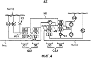
Фиг.4 - скелетная схема, показывающая пример автоматической коробки AT передач, установленной на FR-гибридном транспортном средстве, к которому применяется устройство управления согласно первому варианту осуществления.4 is a skeletal diagram showing an example of an automatic AT transmission mounted on an FR hybrid vehicle to which the control device according to the first embodiment is applied.
Фиг.5 - таблица операции сцепления, показывающая состояния сцепления элементов фрикционного сцепления на отдельных передачах в автоматической коробке AT передач, установленной на FR-гибридном транспортном средстве, к которому применяется устройство управления согласно первому варианту осуществления.5 is a clutch operation table showing the friction clutch engagement states in individual gears in an AT automatic transmission mounted on an FR hybrid vehicle to which the control device according to the first embodiment is applied.
Фиг.6 - блок-схема последовательности операций, показывающая ход процесса оценки начала сцепления для второго тормоза B2 (а именно, тормоза LOW/B низших передач), который выполняется объединенным контроллером, когда операция переключения с N-диапазона на D-диапазон выполняется в первом варианте осуществления.6 is a flowchart showing the progress of the clutch start evaluation process for the second brake B2 (namely, the LOW / B low gear brakes) that is performed by the integrated controller when the switching operation from the N-band to the D-band is performed in the first embodiment.
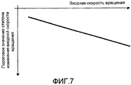
Фиг.7 - карта пороговых значений степени изменения входной скорости вращения, показывающая относительные характеристики степени изменения входной скорости вращения относительно входной скорости вращения, которая используется в операции оценки начала сцепления второго тормоза B2, показанной на фиг.6.Fig.7 is a map of threshold values of the degree of change of the input rotation speed, showing the relative characteristics of the degree of change of the input rotation speed relative to the input rotation speed, which is used in the operation of evaluating the start of adhesion of the second brake B2 shown in Fig.6.
Фиг.8 - карта пороговых значений величины изменения крутящего момента мотора, показывающая относительные характеристики величины изменения крутящего момента мотора относительно входной скорости вращения, которая используется в операции оценки начала сцепления для второго тормоза B2, показанной на фиг.6.Fig. 8 is a map of threshold values of the magnitude of the change in the motor torque showing the relative characteristics of the magnitude of the change in the motor torque relative to the input rotation speed, which is used in the clutch start estimation operation for the second brake B2 shown in Fig. 6.
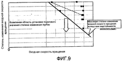
Фиг.9 - диаграмма, показывающая пример экспериментальных данных степени изменения входной скорости вращения относительно входной скорости вращения, которая показывает область, где пороговое значение степени изменения входной скорости вращения может быть установлено.9 is a diagram showing an example of experimental data of the degree of change of the input rotation speed relative to the input rotation speed, which shows the region where the threshold value of the degree of change of the input rotation speed can be set.
Фиг.10 - диаграмма, показывающая пример экспериментальных данных величины изменения крутящего момента мотора относительно входной скорости вращения, которая показывает область, где пороговое значение величины изменения крутящего момента мотора может быть установлено.10 is a diagram showing an example of experimental data of a magnitude of a change in a motor torque relative to an input rotation speed, which shows an area where a threshold value of a magnitude of a change in a motor torque can be set.
Фиг.11 - иллюстративная диаграмма, показывающая пример характеристик настроек порогового значения величины изменения крутящего момента мотора, который основан на экспериментальных данных и сравнительном примере.11 is an illustrative diagram showing an example of settings characteristics of a threshold value of a magnitude of a change in motor torque, which is based on experimental data and a comparative example.
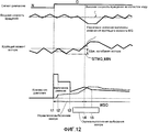
Фиг.12 - временная диаграмма, показывающая характеристики сигнала диапазона, входной скорости вращения, крутящего момента мотора, командного давления для второго тормоза B2 и фактического давления второго тормоза B2, когда операция переключения с N-диапазона на D-диапазон выполняется в условиях высокой скорости вращения холостого хода.12 is a timing chart showing characteristics of a range signal, input rotation speed, motor torque, command pressure for second brake B2 and actual pressure of second brake B2 when switching operation from the N-band to the D-band is performed at high speed idle move.
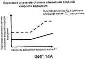
Фиг.13 - блок-схема последовательности операций, показывающая последовательность операций задания порогового значения согласно состояниям сцепления первой муфты согласно второму варианту осуществления.13 is a flowchart showing a sequence of operations for setting a threshold value according to the clutch states of the first clutch according to the second embodiment.
Фиг.14A-14D - иллюстративные схемы, показывающие примеры таблиц для задания пороговых значений второго варианта осуществления.14A-14D are illustrative diagrams showing examples of tables for setting threshold values of a second embodiment.
Способы осуществления изобретенияMODES FOR CARRYING OUT THE INVENTION
Последующее описание описывает наилучшую форму осуществления устройства управления транспортным средством согласно настоящему изобретению со ссылкой на первый вариант осуществления и второй вариант осуществления, показанные на чертежах.The following description describes the best form of implementation of the vehicle control device according to the present invention with reference to the first embodiment and the second embodiment shown in the drawings.
Первый вариант осуществления изобретенияFirst Embodiment
Во-первых, последующее описание описывает конфигурацию устройства управления FR-гибридного транспортного средства типа "один мотор, две муфты" (пример транспортного средства) согласно первому варианту осуществления, и это будет описано отдельно в разделах "Конфигурация всей системы", "Конфигурация автоматической коробки передач" и "Конфигурация процесса оценки начала сцепления".First, the following description describes the configuration of a single-motor, two-clutch type FR-hybrid vehicle control device (vehicle example) according to the first embodiment, and this will be described separately in the sections “System-wide configuration”, “Automatic box configuration gears "and" Configuring the clutch start evaluation process. "
Конфигурация всей системыWhole system configuration
Фиг.1 показывает FR-гибридное транспортное средство, к которому применяется устройство управления согласно первому варианту осуществления. Фиг.2 показывает пример карты переключения автоматической коробки "AT" передач, которая задается в AT-контроллере 7 согласно первому варианту осуществления. Фиг.3 показывает пример карты выбора EV-HEV, которая задается в части выбора режима объединенного контроллера 10 согласно первому варианту осуществления. Последующее описание описывает конфигурацию всей системы со ссылкой на фиг.1-3.FIG. 1 shows an FR hybrid vehicle to which a control device according to a first embodiment is applied. FIG. 2 shows an example of a shift map of an automatic “AT” gearbox that is set in the AT controller 7 according to the first embodiment. FIG. 3 shows an example of an EV-HEV selection card that is set in the mode selection part of the combined controller 10 according to the first embodiment. The following description describes the configuration of the entire system with reference to FIGS. 1-3.
Как показано на фиг.1, трансмиссия FR-гибридного транспортного средства включает в себя двигатель "Eng", маховик "FW", первую муфту CL1, мотор-генератор "MG" (мотор), вторую муфту CL2, автоматическую коробку AT передач, входной вал "IN" коробки передач, главный маслонасос "M-O/P", вспомогательный маслонасос "S-O/P", карданный вал "PS", шестерню "DF" дифференциала, левый ведущий вал "DSL", правый ведущий вал "DSR", левое заднее колесо "RL" (ведущее колесо) и правое заднее колесо "RR" (ведущее колесо). "FL" представляет левое переднее колесо, а "FR" представляет правое переднее колесо.As shown in FIG. 1, the transmission of an FR hybrid vehicle includes an Eng engine, a FW flywheel, a first clutch CL1, an MG motor generator (motor), a second clutch CL2, an automatic AT gearbox, an input gearbox shaft “IN”, main oil pump “MO / P”, auxiliary oil pump “SO / P”, driveshaft “PS”, differential gear “DF”, left drive shaft “DSL”, right drive shaft “DSR”, left rear wheel "RL" (drive wheel) and right rear wheel "RR" (drive wheel). “FL” represents the left front wheel and “FR” represents the right front wheel.
Двигатель Eng является бензиновым двигателем или дизельным двигателем, который управляется на основе команды управления двигателем от контроллера 1 двигателя, так что выполняются управление запуском двигателя, управление остановкой двигателя, управление открытием дроссельной заслонки, управление прекращением подачи топлива и другие. Маховик FW присоединен к выходному валу двигателя.Eng engine is a gasoline engine or diesel engine, which is controlled based on the engine control command from the
Первая муфта CL1 размещена между двигателем Eng и мотор-генератором MG и управляется, чтобы полностью сцепляться, или сцепляться с возможностью проскальзывания, или полностью расцепляться посредством управляющего гидравлического давления первой муфты, которое создается посредством гидравлического блока 6 первой муфты на основе управляющей команды первой муфты от контроллера 5 первой муфты.The first clutch CL1 is located between the eng engine Eng and the motor generator MG and is controlled to fully engage, or to engage with the possibility of slipping, or to completely disengage through the control hydraulic pressure of the first coupling, which is generated by the
Мотор-генератор MG является синхронным мотор-генератором, в котором постоянный магнит вставлен в ротор и обмотка статора обмотана вокруг статора. Мотор-генератор MG управляется на основе управляющей команды от контроллера 2 мотора, так что трехфазные переменные токи генерируются и прикладываются к мотор-генератору MG посредством инвертора 3. Мотор-генератор MG может функционировать в качестве мотора, который вращается на основе подачи энергии от аккумулятора 4 ("движение от электрической мощности"), и функционировать также в качестве электрогенератора, чтобы заряжать аккумулятор 4, посредством формирования электродвижущей силы между концами обмотки статора, когда ротор получает вращательную энергию от двигателя Eng и ведущих колес ("рекуперация"). Ротор мотор-генератора MG соединен с входным валом IN коробки передач для автоматической коробки AT передач.The MG motor generator is a synchronous motor generator in which a permanent magnet is inserted into the rotor and the stator winding is wound around the stator. The MG motor generator is controlled based on a control command from the
Вторая муфта CL2 размещается между мотор-генератором MG и левым и правым задними колесами RL, RR. Вторая муфта CL2 является элементом сцепления для начала движения, который сцепляется, когда выполняется операция переключения с N-диапазона на D-диапазон (или R-диапазон). Вторая муфта CL2 управляется, чтобы быть полностью сцепленной, сцепленной с возможностью проскальзывания или полностью расцепленной, посредством управляющего гидравлического давления, которое создается посредством гидравлического блока 8 второй муфты на основе команды управления второй муфтой от AT-контроллера 7. Например, вторая муфта CL2 реализована посредством обычно разомкнутой многодисковой муфты мокрого типа или тормоза, при этом скорость потока и гидравлическое давление рабочей жидкости может управляться непрерывно посредством электромагнитного пропорционального клапана. Гидравлический блок 6 первой муфты и гидравлический блок 8 второй муфты установлены в блоке управления гидравлическим клапаном "CVU", который предусмотрен с автоматической коробкой AT передач.The second clutch CL2 is located between the motor generator MG and the left and right rear wheels RL, RR. The second clutch CL2 is a clutch for starting movement, which engages when a shift operation from the N-band to the D-band (or R-band) is performed. The second clutch CL2 is controlled to be fully engaged, slippage coupled or completely disengaged by the hydraulic control pressure that is generated by the hydraulic unit 8 of the second coupling based on the command control of the second coupling from the AT controller 7. For example, the second coupling CL2 is implemented by a normally open wet-type multi-plate clutch or brake, wherein the flow rate and hydraulic pressure of the working fluid can be continuously controlled by lektromagnitnogo proportional valve. The
Автоматическая коробка AT передач размещает вторую муфту CL2 в качестве элемента сцепления. Автоматическая коробка AT передач является коробкой передач, которая автоматически переключается между множеством ступенчатых положений передач, в зависимости от скорости транспортного средства и открытия педали акселератора. Входной вал IN коробки передач для автоматической коробки AT передач (а именно, вал мотора) снабжен главным маслонасосом M-O/P, который приводится в действие посредством входного вала IN коробки передач. Вспомогательный маслонасос S-O/P предусмотрен в корпусе мотора или т.п. Вспомогательный маслонасос S-O/P приводится в действие мотором для пресечения падения гидравлического давления, когда сброс давления главного маслонасоса M-O/P является коротким, в то время как транспортное средство неподвижно или в аналогичных случаях. Управление приведением в действие вспомогательного маслонасоса S-O/P выполняется AT-контроллером 7, описанным ниже. Выходной вал коробки передач для автоматической коробки AT передач соединяется с карданным валом PS. Карданный вал PS соединяется с левым и правым задними колесами RL, RR через шестерню DF дифференциала, левый ведущий вал DSL и правый ведущий вал DSR.An automatic AT gearbox places the second clutch CL2 as a clutch member. An automatic AT gearbox is a gearbox that automatically switches between a multitude of gear positions, depending on the speed of the vehicle and the opening of the accelerator pedal. The input shaft IN of the gearbox for an automatic AT gearbox (namely, the motor shaft) is equipped with a main oil pump M-O / P, which is driven by the input shaft IN of the gearbox. The auxiliary oil pump S-O / P is provided in a motor housing or the like. The auxiliary oil pump S-O / P is driven by the motor to suppress a drop in hydraulic pressure when the pressure relief of the main oil pump M-O / P is short while the vehicle is stationary or in similar cases. The actuation of the auxiliary oil pump S-O / P is controlled by the AT controller 7 described below. The output shaft of the gearbox for the automatic AT gearbox is connected to the driveshaft PS. The PS drive shaft is connected to the left and right rear wheels RL, RR through the differential gear DF, the left DSL drive shaft and the right DSR drive shaft.
Гибридное транспортное средство применяет режимы приведения в движение, которые отличаются по форме приведения в движение, при этом режимы приведения в движение включают в себя режим электрического транспортного средства (в дальнейшем называемый "EV-режимом"), режим гибридного транспортного средства (в дальнейшем называемый "HEV-режимом") и режим управления крутящим моментом приведения в движение (в дальнейшем называемый "WSC-режимом").The hybrid vehicle employs propulsion modes that differ in the form of propulsion, wherein the propulsion modes include an electric vehicle mode (hereinafter referred to as "EV mode"), a hybrid vehicle mode (hereinafter referred to as " HEV mode ") and the driving torque control mode (hereinafter referred to as the" WSC mode ").
EV-режим - это режим, в котором первая муфта CL1 расцеплена и транспортное средство приводится в движение только посредством движущей силы мотор-генератора MG. EV-режим включает в себя режим приведения в движение от мотора и режим рекуперативного приведения в движение. EV-режим выбирается, например, когда требуемая движущая сила является небольшой и SOC аккумулятора является достаточным.The EV mode is a mode in which the first clutch CL1 is disengaged and the vehicle is driven only by the driving force of the motor generator MG. The EV mode includes a propulsion mode from a motor and a regenerative propulsion mode. The EV mode is selected, for example, when the required driving force is small and the battery SOC is sufficient.
HEV-режим - это режим, в котором транспортное средство приводится в движение со сцепленной первой муфтой CL1. HEV-режим включает в себя режим приведения в движение с помощью мотора, режим выработки электрической энергии и режим приведения в движение от двигателя, один из которых выбирается для движения транспортного средства. HEV-режим выбирается, например, когда требуемая движущая сила является большой или когда SOC аккумулятора недостаточно.The HEV mode is a mode in which the vehicle is driven with the first clutch CL1 engaged. The HEV mode includes a motor driving mode, an electric power generation mode, and a motor driving mode, one of which is selected for driving a vehicle. The HEV mode is selected, for example, when the required driving force is large or when the SOC of the battery is insufficient.
WSC-режим - это режим, в котором вторая муфта CL2 сцеплена с возможностью проскальзывания и максимальный крутящий момент второй муфты CL2 управляется так, что передаваемый муфтой крутящий момент, проходящий через вторую муфту CL2, удовлетворяет требуемому крутящему моменту приведения в движение, определенному в зависимости от операции водителя или т.п. WSC-режим выбирается, когда скорость вращения ведущего колеса получается ниже скорости вращения двигателя, так что необходимо компенсировать дифференциальное вращение между ними посредством проскальзывания второй муфты CL2, например, когда транспортное средство неподвижно или находится в области начала ускорения.The WSC mode is a mode in which the second clutch CL2 is slidably coupled and the maximum torque of the second clutch CL2 is controlled so that the torque transmitted by the clutch passing through the second clutch CL2 satisfies the required driving torque determined depending on driver operations or the like The WSC mode is selected when the speed of the drive wheel is lower than the speed of the engine, so it is necessary to compensate for the differential rotation between them by slipping the second clutch CL2, for example, when the vehicle is stationary or is in the area of the start of acceleration.
Последующее описание описывает систему управления FR-гибридного транспортного средства. Как показано на фиг.1, система управления FR-гибридного транспортного средства включает в себя контроллер 1 двигателя, контроллер 2 мотора, инвертор 3, аккумулятор 4, контроллер 5 первой муфты, гидравлический блок 6 первой муфты, AT-контроллер 7, гидравлический блок 8 второй муфты, контроллер 9 тормоза и объединенный контроллер 10. Контроллеры 1, 2, 5, 7 и 9 и объединенный контроллер 10 соединены через CAN-линию 11 связи для обмена информацией друг с другом.The following description describes the control system of an FR hybrid vehicle. As shown in FIG. 1, the control system of the FR hybrid vehicle includes an
Контроллер 1 двигателя принимает входную информацию о скорости вращения двигателя от датчика 12 скорости вращения двигателя и входную команду целевого крутящего момента двигателя от объединенного контроллера 10 и входную другую необходимую информацию. Контроллер 1 двигателя выводит команду для управления рабочей точкой двигателя (Ne, Te) актуатору дроссельной заслонки двигателя Eng и другим.The
Контроллер 2 мотора принимает входную информацию от датчика 13 положения, который обнаруживает угловое положение ротора мотор-генератора MG, и входную команду целевого крутящего момента MG и команду целевой скорости вращения MG от объединенного контроллера 10 и входную другую необходимую информацию. Контроллер 2 мотора выводит инвертору 3 команду для управления рабочей точкой мотора (Nm, Tm) мотор-генератора MG. Контроллер 2 мотора наблюдает за SOC аккумулятора, указывающим состояние заряда аккумулятора 4, и предоставляет информацию о SOC аккумулятора объединенному контроллеру 10 через CAN-линию 11 связи.The
Контроллер 5 первой муфты принимает входную информацию датчика от датчика 15 хода первой муфты, который обнаруживает положение хода поршня 14a гидравлического актуатора 14, и входную команду целевого крутящего момента CL1 от объединенного контроллера 10 и входную другую необходимую информацию. Контроллер 5 первой муфты выводит команду для управления сцеплением и расцеплением первой муфты CL1 гидравлическому блоку 6 первой муфты в блоке CVU управления гидравлическим клапаном.The
AT-контроллер 7 принимает входную информацию от датчика 16 открытия акселератора, датчика 17 скорости транспортного средства, переключателя 18 нейтрали и т.д. Когда транспортное средство движется с выбранным D-диапазоном, оптимальное положение передачи определяется на основе положения рабочей точки в карте переключения, показанной на фиг.2, при этом рабочая точка определяется посредством открытия APO педали акселератора и скорости VSP транспортного средства, и управляющая команда для получения найденного положения передачи выводится блоку CVU управления гидравлическим клапаном. В дополнение к этому управлению переключением, если команда целевого крутящего момента CL2 вводится от объединенного контроллера 10, выполняется управление второй муфтой, чтобы выводить команду для управления сцеплением с возможностью проскальзывания второй муфты CL2 гидравлическому блоку 8 второй муфты в блоке CVU управления гидравлическим клапаном.The AT controller 7 receives input from the accelerator opening sensor 16, the vehicle speed sensor 17, the neutral switch 18, etc. When the vehicle is traveling with the selected D-range, the optimal gear position is determined based on the position of the operating point in the shift map shown in FIG. 2, the operating point being determined by opening the accelerator pedal APO and vehicle speed VSP, and a control command to obtain the found gear position is output to the hydraulic valve control unit CVU. In addition to this shift control, if the target torque command CL2 is input from the combined controller 10, the second clutch is controlled to output a clutch control command for the second clutch to slip to the hydraulic unit 8 of the second clutch in the hydraulic valve control unit CVU.
Контроллер 9 тормоза принимает входную информацию датчика от датчика 19 скорости вращения колеса для измерения скорости вращения колеса каждого из четырех колес и датчика 20 хода тормоза и входную команду управления совместной рекуперацией от объединенного контроллера 10 и входную другую необходимую информацию. Например, когда педаль тормоза нажимается для торможения и запрошенное тормозное усилие, вычисленное из хода BS тормоза, не удовлетворяется только посредством рекуперативного тормозного усилия, контроллер 9 тормоза выполняет управление совместным рекуперативным торможением для покрытия нехватки с помощью механического тормозного усилия (гидравлического тормозного усилия или усилия торможения мотором).The
Объединенный контроллер 10 управляет потребляемой энергией всего транспортного средства и функционирует, чтобы предоставлять возможность транспортному средству двигаться с оптимизированной эффективностью. Объединенный контроллер 10 принимает входную необходимую информацию от датчика 21 скорости вращения мотора для измерения скорости Nm вращения мотора и других датчиков, переключателей и т.д. 22 и входную информацию через CAN-линию 11 связи. Объединенный контроллер 10 выводит команду целевого крутящего момента двигателя контроллеру 1 двигателя, команду целевого крутящего момента MG и команду целевой скорости вращения MG контроллеру 2 мотора, команду целевого крутящего момента CL1 контроллеру 5 первой муфты, команду целевого крутящего момента CL2 AT-контроллеру 7 и команду управления совместным рекуперативным торможением контроллеру 9 тормоза.The combined controller 10 controls the energy consumption of the entire vehicle and functions to enable the vehicle to move with optimized efficiency. The combined controller 10 receives the necessary input information from the motor speed sensor 21 for measuring the motor rotation speed Nm and other sensors, switches, etc. 22 and input via the CAN line 11. The combined controller 10 outputs the target engine torque command to the
Объединенный контроллер 10 включает в себя секцию выбора режима, которая определяет оптимальный режим приведения в движение в зависимости от позиции рабочей точки на карте выбора EV-HEV, показанной на фиг.3, при этом рабочая точка определяется посредством открытия APO педали акселератора и скорости VSP транспортного средства, и выбирает найденный режим приведения в движение в качестве целевого режима приведения в движение. В карте выбора EV-HEV заданы линия переключения с EV на HEV для переключения из EV-режима в HEV-режим, линия переключения с HEV на EV для переключения из HEV-режима в EV-режим и линия переключения с WSC на HEV для переключения из WSC-режима на HEV-режим. Линия переключения с EV на HEV и линия переключения с HEV на EV заданы с величиной гистерезиса. Линия переключения с WSC на HEV задана согласно первой заданной скорости VSP1 транспортного средства, с которой двигатель Eng поддерживает скорость вращения холостого хода в положении первой передачи автоматической коробки AT передач. Однако когда SOC аккумулятора становится ниже или равно предварительно определенному значению, в то время как выбран EV-режим, целевой режим приведения в движение принудительно устанавливается в HEV-режим.The combined controller 10 includes a mode selection section that determines the optimum driving mode depending on the position of the operating point on the EV-HEV selection map shown in FIG. 3, wherein the operating point is determined by opening the accelerator pedal APO and the vehicle speed VSP means, and selects the found driving mode as the target driving mode. In the EV-HEV selection map, a switching line from EV to HEV is set for switching from EV mode to HEV mode, a switching line from HEV to EV for switching from HEV mode to EV mode and a switching line from WSC to HEV to switch from WSC mode to HEV mode. The switching line from EV to HEV and the switching line from HEV to EV are set with a hysteresis value. The WSC to HEV shift line is set according to a first predetermined vehicle speed VSP1 at which the engine Eng maintains the idle speed in the first gear position of the automatic AT transmission. However, when the battery SOC becomes lower than or equal to a predetermined value while the EV mode is selected, the target driving mode is forcibly set to the HEV mode.
Конфигурация автоматической коробки передачAutomatic Transmission Configuration
Фиг.4 показывает пример автоматической коробки AT передач, установленной на FR-гибридном транспортном средстве, к которой применяется устройство управления согласно первому варианту осуществления. Фиг.5 показывает состояния сцепления элементов фрикционного сцепления на отдельных передачах в автоматической коробке AT передач, установленной на FR-гибридном транспортном средстве, к которой применяется устройство управления согласно первому варианту осуществления. Последующее описание описывает конфигурацию автоматической коробки AT передач со ссылкой на фиг.4 и 5.FIG. 4 shows an example of an automatic AT transmission mounted on an FR hybrid vehicle to which a control device according to the first embodiment is applied. FIG. 5 shows the friction clutch engagement states in individual gears in an automatic AT gearbox mounted on an FR hybrid vehicle to which the control device according to the first embodiment is applied. The following description describes the configuration of an automatic AT transmission with reference to FIGS. 4 and 5.
Автоматическая коробка AT передач является ступенчатой автоматической коробкой передач с семью передачами переднего хода и одной передачей заднего хода. Автоматическая коробка AT передач принимает входную движущую силу, по меньшей мере, одного из двигателя Eng и мотор-генератора MG через входной вал "Input" коробки передач и переключает скорость вращения посредством четырех планетарных шестерен и семи элементов фрикционного сцепления и выводит ее через выходной вал "Output" коробки передач.The AT automatic transmission is a speed automatic transmission with seven forward gears and one reverse gear. The AT automatic gearbox receives the input driving force of at least one of the Eng engine and the MG motor generator through the gearbox input shaft “Input” and switches the rotation speed through four planetary gears and seven friction clutch elements and outputs it through the output shaft " Output "gearbox.
Автоматическая коробка AT передач включает в себя зубчатый механизм переключения передач, включающий в себя первый планетарный набор GS1 и второй планетарный набор GS2, которые размещены вдоль оси, протягивающейся от входного вала Input коробки передач к выходному валу Output коробки передач. Первый планетарный набор GS1 включает в себя первую планетарную передачу G1 и вторую планетарную передачу G2. Второй планетарный набор GS2 включает в себя третью планетарную передачу G3 и четвертую планетарную передачу G4. Более того, первая муфта C1, вторая муфта C2, третья муфта C3, первый тормоз B1, второй тормоз B2, третий тормоз B3 и четвертый тормоз B4 размещены в качестве элементов фрикционного сцепления. Кроме того, размещены первая односторонняя муфта F1 и вторая односторонняя муфта F2.The AT automatic transmission includes a gear shift mechanism including a first planetary gear set GS1 and a second planetary gear set GS2, which are arranged along an axis extending from the input shaft of the gearbox input to the output shaft of the gearbox output. The first planetary gear set GS1 includes a first planetary gear G1 and a second planetary gear G2. The second GS2 planetary gear set includes a third planetary gear G3 and a fourth planetary gear G4. Moreover, the first clutch C1, the second clutch C2, the third clutch C3, the first brake B1, the second brake B2, the third brake B3 and the fourth brake B4 are arranged as friction clutch elements. In addition, the first one-way clutch F1 and the second one-way clutch F2 are placed.
Первая планетарная передача G1 включает в себя первую солнечную шестерню S1, первую коронную шестерню R1, первый сателлит P1 и первое водило PC1. Вторая планетарная передача G2 включает в себя вторую солнечную шестерню S2, вторую коронную шестерню R2, второй сателлит P2 и второе водило PC2. Третья планетарная передача G3 включает в себя третью солнечную шестерню S3, третью коронную шестерню R3, третий сателлит P3 и третье водило PC3. Четвертая планетарная передача G4 включает в себя четвертую солнечную шестерню S4, четвертую коронную шестерню R4, четвертый сателлит P4 и четвертое водило PC4. А именно, первая-четвертая планетарные передачи G1-G4 являются планетарными передачами с одним сателлитом.The first planetary gear G1 includes a first sun gear S1, a first ring gear R1, a first satellite P1 and a first carrier PC1. The second planetary gear G2 includes a second sun gear S2, a second ring gear R2, a second satellite P2 and a second carrier PC2. The third planetary gear G3 includes a third sun gear S3, a third ring gear R3, a third satellite P3 and a third carrier PC3. The fourth planetary gear G4 includes a fourth sun gear S4, a fourth ring gear R4, a fourth satellite P4 and a fourth carrier PC4. Namely, the first to fourth planetary gears G1-G4 are planetary gears with one satellite.
Входной вал Input коробки передач соединен со второй коронной шестерней R2 и принимает входной крутящий момент приведения в движение, по меньшей мере, от одного из двигателя Eng и мотор-генератора MG. Выходной вал Output коробки передач соединен с третьим водилом PC3 и передает выходной крутящий момент приведения в движение через редуктор и т.п. ведущим колесам (левому и правому задним колесам RL, RR).The input shaft Input of the gearbox is connected to the second ring gear R2 and receives the input torque of driving from at least one of the engine Eng and the motor generator MG. The output shaft Output of the gearbox is connected to the third carrier PC3 and transmits the output torque of the driving through the gearbox, etc. driving wheels (left and right rear wheels RL, RR).
Первая коронная шестерня R1, второе водило PC2 и четвертая коронная шестерня R4 соединены вместе посредством первого соединительного элемента M1. Третья коронная шестерня R3 и четвертое водило PC4 соединены вместе посредством второго соединительного элемента M2. Первая солнечная шестерня S1 и вторая солнечная шестерня S2 соединены вместе посредством третьего соединительного элемента M3.The first ring gear R1, the second carrier PC2, and the fourth ring gear R4 are connected together by the first connecting member M1. The third ring gear R3 and the fourth carrier PC4 are connected together by the second connecting member M2. The first sun gear S1 and the second sun gear S2 are connected together by a third connecting member M3.
Первая муфта C1 (а именно, входная муфта I/C) выборочно соединяет входной вал Input коробки передач со вторым соединительным элементом M2 и отсоединяет входной вал Input коробки передач от второго соединительного элемента M2. Вторая муфта C2 (а именно, муфта D/C прямой передачи) выборочно соединяет четвертую солнечную шестерню S4 с четвертым водилом PC4 и отсоединяет четвертую солнечную шестерню S4 от четвертого водила PC4. Третья муфта C3 (а именно, H&LR муфта H&LR/C) выборочно соединяет третью солнечную шестерню S3 с четвертой солнечной шестерней S4 и отсоединяет третью солнечную шестерню S3 от четвертой солнечной шестерни S4. Вторая односторонняя муфта F2 (а именно, односторонняя муфта 1&2OWC первой и второй передачи) предусмотрена между третьей солнечной шестерней S3 и четвертой солнечной шестерней S4 и выборочно соединяется и отсоединяется механически. Первый тормоз B1 (а именно, передний тормоз Fr/B) выборочно удерживает первое водило PC1 неподвижно относительно картера "Case" коробки передач и предоставляет возможность первому водилу PC1 вращаться относительно картера Case коробки передач. Первая односторонняя муфта F1 (а именно, односторонняя муфта 1stOWC первой передачи) размещена параллельно первому тормозу B1 и выборочно соединяется и отсоединяется механически. Второй тормоз B2 (а именно, тормоз LOW/B нижней передачи) выборочно удерживает третью солнечную шестерню S3 неподвижно относительно картера Case коробки передач и предоставляет возможность третьей солнечной шестерне S3 вращаться относительно картера Case коробки передач. Третий тормоз B3 (а именно, 2346-тормоз "2346/B") выборочно удерживает третий соединительный элемент M3 неподвижным относительно картера Case коробки передач и предоставляет возможность третьему соединительному элементу M3 вращаться относительно картера Case коробки передач, при этом третий соединительный элемент M3 соединяет первую солнечную шестерню S1 и вторую солнечную шестерню S2 вместе. Четвертый тормоз B4 (а именно, тормоз R/B заднего хода) выборочно удерживает третье водило PC3 неподвижным относительно картера Case коробки передач и предоставляет возможность третьему водилу PC3 вращаться относительно картера Case коробки передач.The first clutch C1 (namely, the input I / C clutch) selectively connects the input shaft of the gearbox Input to the second connecting member M2 and disconnects the input shaft of the gearbox Input from the second connecting member M2. The second clutch C2 (namely, the direct-drive clutch D / C) selectively connects the fourth sun gear S4 to the fourth carrier PC4 and disconnects the fourth sun gear S4 from the fourth carrier PC4. The third clutch C3 (namely, the H&LR clutch H & LR / C) selectively connects the third sun gear S3 to the fourth sun gear S4 and disconnects the third sun gear S3 from the fourth sun gear S4. A second one-way clutch F2 (namely, a one-
Последующее описание описывает операцию сцепления в каждом положении передачи со ссылкой на фиг.5. В таблице операции сцепления на фиг.5 каждый незаштрихованный кружок представляет условия, в которых соответствующий элемент фрикционного сцепления гидравлически вовлекается в состояние приведения в движение, а каждый заключенный в скобки незаштрихованный кружок представляет условия, в которых соответствующий элемент фрикционного сцепления гидравлически вовлекается в состояние движения по инерции (он функционирует как односторонняя муфта в состоянии приведения в движение), и каждая пустая ячейка представляет условия, в которых соответствующий элемент фрикционного сцепления расцеплен.The following description describes a clutch operation in each gear position with reference to FIG. In the clutch operation table of FIG. 5, each open circle indicates the conditions in which the corresponding friction clutch element is hydraulically engaged in the driving state, and each open circle enclosed in brackets represents the conditions in which the corresponding friction clutch element is hydraulically engaged in inertia (it functions as a one-way clutch in a state of propulsion), and each empty cell represents the conditions in which sponding element of the friction clutch is disengaged.
Каждое из семи положений передач получается посредством переключателя сцепления, включающего в себя переключение одного из элементов фрикционного сцепления, предусмотренных в зубчатом механизме переключения передач, сконструированном, как описано выше, из сцепленного состояния в расцепленное состояние и переключение другого из элементов фрикционного сцепления из расцепленного состояния в сцепленное состояние, как описано ниже. Кроме того, получается одно положение передачи заднего хода.Each of the seven gear positions is obtained by means of a clutch switch, which includes switching one of the friction clutch elements provided in the gear shift mechanism constructed as described above from the engaged state to the disengaged state and switching the other of the friction clutch elements from the disengaged state to linked state as described below. In addition, you get one reverse gear position.
На первой передаче сцеплены первый тормоз B1 (со сцеплением первой однонаправленной муфты F1) и третья муфта C3 (со сцеплением второй однонаправленной муфты F2) и второй тормоз B2. На второй передаче сцеплены третья муфта C3 (со сцеплением второй однонаправленной муфты F2) и второй тормоз B2 и третий тормоз B3. На третьей передаче сцеплены второй тормоз B2, третий тормоз B3 и вторая муфта C2. На четвертой передаче сцеплены третий тормоз B3, вторая муфта C2 и третья муфта C3. На пятой передаче сцеплены первая муфта C1, вторая муфта C2 и третья муфта C3. На шестой передаче сцеплены третий тормоз B3, первая муфта C1 и третья муфта C3. На седьмой передаче сцеплены первый тормоз B1 (со сцеплением первой односторонней муфты F1) и первая муфта C1 и третья муфта C3. На передаче заднего хода сцеплены четвертый тормоз B4, первый тормоз B1 и третья муфта C3. Таким образом, во время переключения с N-диапазона на D-диапазон сцепляется второй тормоз B2 (а именно, тормоз LOW/B низших передач). Соответственно, второй тормоз B2 является элементом фрикционного сцепления, на который нацелена оценка начала сцепления согласно первому варианту осуществления.In first gear, the first brake B1 (with the clutch of the first unidirectional clutch F1) and the third clutch C3 (with the clutch of the second unidirectional clutch F2) and the second brake B2 are engaged. In second gear, the third clutch C3 (with the clutch of the second unidirectional clutch F2) and the second brake B2 and the third brake B3 are engaged. In third gear, a second brake B2, a third brake B3 and a second clutch C2 are engaged. In fourth gear, a third brake B3, a second clutch C2, and a third clutch C3 are engaged. In fifth gear, the first clutch C1, the second clutch C2 and the third clutch C3 are engaged. In sixth gear, a third brake B3, a first clutch C1 and a third clutch C3 are engaged. In seventh gear, the first brake B1 (with the clutch of the first one-way clutch F1) and the first clutch C1 and the third clutch C3 are engaged. In reverse gear, a fourth brake B4, a first brake B1 and a third clutch C3 are engaged. Thus, when switching from the N-band to the D-band, the second brake B2 is engaged (namely, the LOW / B lower gear brake). Accordingly, the second brake B2 is a friction clutch member that is targeted at the clutch start assessment according to the first embodiment.
Конфигурация процесса оценки начала сцепленияThe clutch start evaluation process configuration
Фиг.6 - это блок-схема последовательности операций, показывающая последовательность операций процесса оценки начала сцепления относительно второго тормоза B2 (а именно, тормоза LOW/B низших передач), который выполняется посредством объединенного контроллера 10, когда выполняется операция переключения с N-диапазона на D-диапазон, согласно первому варианту осуществления. Последующее описание описывает этапы на фиг.6, которые составляют процесс оценки начала сцепления. Процесс управления на фиг.6 выполняется многократно с интервалами предварительно определенного периода времени начала управления.6 is a flowchart showing a process of evaluating a clutch start with respect to a second brake B2 (namely, a lower gear LOW / B brake) that is performed by the integrated controller 10 when the switching operation from the N-band to D-band according to the first embodiment. The following description describes the steps in FIG. 6, which constitute the process of evaluating the start of adhesion. The control process of FIG. 6 is performed repeatedly at intervals of a predetermined time period for the start of control.
На этапе S1 объединенный контроллер 10 оценивает, выполнена или нет операция переключения с N-диапазона на D-диапазон, на основе переключения сигнала положения диапазона от переключателя 18 нейтрали с сигнала N-диапазона на сигнал D-диапазона. Когда ответ - да (когда операция переключения с N-диапазона на D-диапазон выполнена), процесс переходит к этапу S3. Когда ответ - нет (когда выбран N-диапазон), процесс переходит к этапу S2.In step S1, the combined controller 10 evaluates whether or not the switching operation from the N-band to the D-band is performed based on switching the range position signal from the neutral switch 18 from the N-band signal to the D-band signal. When the answer is yes (when the operation of switching from the N-band to the D-band is completed), the process proceeds to step S3. When the answer is no (when the N-band is selected), the process proceeds to step S2.
На этапе S2, следом за оценкой на этапе S1 того, что выбирается N-диапазон, объединенный контроллер 10 выполняет управление скоростью вращения мотора, в котором целевая скорость вращения устанавливается в целевую скорость вращения холостого хода (переменная скорость вращения), и переходит к окончанию процесса. Целевая скорость вращения холостого хода устанавливается в высокую скорость вращения холостого хода, когда температура охлаждающей жидкости двигателя находится в очень низком температурном диапазоне, при этом высокая скорость вращения холостого хода выше обычной скорости вращения холостого хода. Когда температура охлаждающей жидкости двигателя растет посредством операции прогрева, целевая скорость вращения холостого хода устанавливается постепенно снижающейся с высокой скорости вращения холостого хода до нормальной скорости вращения холостого хода. После того как температура охлаждающей жидкости двигателя превышает или становится равной предварительно определенной температуре, целевая скорость вращения холостого хода удерживается в нормальной скорости вращения холостого хода.In step S2, following the assessment in step S1 that the N-band is selected, the combined controller 10 controls the speed of the motor in which the target rotation speed is set to the target idle speed (variable speed) and proceeds to the end of the process . The target idle speed is set to a high idle speed when the engine coolant temperature is in a very low temperature range, while the high idle speed is higher than the normal idle speed. When the engine coolant temperature rises through the warm-up operation, the target idle speed is set to gradually decrease from the high idle speed to the normal idle speed. After the engine coolant temperature exceeds or becomes equal to a predetermined temperature, the target idle speed is held at the normal idle speed.
На этапе S3, следом за оценкой на этапе S1, что операция переключения с N-диапазона на D-диапазон выполнена, объединенный контроллер 10 переключает целевую скорость вращения с целевой скорости вращения в управлении скоростью вращения мотора, когда выбран N-диапазон (переменная скорость вращения), на входную скорость вращения коробки передач во время операции переключения с N-диапазона на D-диапазон (фиксированная скорость вращения), и затем процесс переходит к этапу S4 (средство управления поддерживает входную скорость вращения). А именно, после операции переключения с N-диапазона на D-диапазон управление скоростью вращения мотора выполняется с тем, чтобы удерживать входную скорость вращения коробки передач во время операции переключения с N-диапазона на D-диапазон.In step S3, following the assessment in step S1 that the switching operation from the N-band to the D-band is completed, the combined controller 10 switches the target speed from the target speed in controlling the motor speed when the N-band is selected (variable speed ), to the input gearbox rotation speed during the operation of switching from the N-band to the D-band (fixed rotational speed), and then the process proceeds to step S4 (the control means supports the input rotational speed). Namely, after the operation of switching from the N-band to the D-band, the rotation speed of the motor is controlled in order to maintain the input gearbox rotation speed during the operation of switching from the N-band to the D-band.
На этапе S4, следом за переключением целевой скорости вращения в управлении скоростью вращения мотора на этапе S3, объединенный контроллер 10 подсчитывает время таймера, прошедшее после ND-переключения, которое указывает период времени, прошедший после операции переключения с N-диапазона на D-диапазон, и затем процесс переходит к этапу S5.In step S4, after switching the target rotation speed in controlling the motor rotation speed in step S3, the combined controller 10 calculates a timer elapsed after the ND switch, which indicates a period of time elapsed after the switching operation from the N-band to the D-band, and then the process goes to step S5.
На этапе S5, следом за подсчетом времени таймера, прошедшего после ND-переключения на этапе S4, объединенный контроллер 10 выполняет операцию вычисления для вычисления величины изменения входной скорости вращения, которая является величиной уменьшения скорости вращения от входной скорости вращения коробки передач во время операции переключения с N-диапазона на D-диапазон, и затем процесс переходит к этапу S6.In step S5, after counting the timer elapsed after the ND switch in step S4, the combined controller 10 performs a calculation operation to calculate a change in the input rotation speed, which is a decrease in the rotation speed from the input rotation speed of the gearbox during the shift operation from N-band to D-band, and then the process proceeds to step S6.
На этапе S6, следом за операцией вычисления величины изменения входной скорости вращения на этапе S5, объединенный контроллер 10 определяет, превышает или нет время таймера, прошедшее после ND-переключения, или становится равным временному периоду запрета вычисления оценки выбирания зазора. Когда ответ - да (время таймера, прошедшее после ND-переключения, ≥ временного периода запрета вычисления оценки выбирания зазора), процесс переходит к этапу S7. Когда ответ - нет (время таймера, прошедшее после ND-переключения, < временного периода запрета вычисления оценки выбирания зазора), процесс возвращается к этапу S4. Временной период запрета вычисления оценки выбирания зазора устанавливается во временной период, когда возможна некорректная оценка выбирания зазора, поскольку возможно, что степень изменения входной скорости вращения (этапы S7) и величина изменения крутящего момента мотора (этап S8), которые используются для оценки выбирания зазора, вычислены как избыточные в абсолютном значении.In step S6, following the operation of calculating the magnitude of the change in the input rotation speed in step S5, the combined controller 10 determines whether or not the timer elapsed after the ND switch exceeds or becomes equal to the time period of the prohibition of calculating the gap selection estimate. When the answer is yes (the timer elapsed after the ND switch, ≥ the time period of the prohibition of calculating the gap selection estimate), the process proceeds to step S7. When the answer is no (the timer elapsed after the ND switch, <the time period of the prohibition of calculating the gap selection estimate), the process returns to step S4. The time period for the prohibition of calculating the clearance selection estimate is set to the time period when an incorrect assessment of the clearance selection is possible, since it is possible that the degree of change in the input rotation speed (steps S7) and the magnitude of the change in the motor torque (step S8), which are used to evaluate the selection of the gap, calculated as redundant in absolute value.
На этапе S7, следом за оценкой, что время таймера, прошедшее после ND-переключения, ≥ временного периода запрета вычисления оценки выбирания зазора на этапе S6, объединенный контроллер 10 выполняет операцию вычисления для вычисления степени изменения входной скорости вращения, которая является степенью изменения скорости вращения входного вала Input коробки передач, и затем процесс переходит к этапу S8. Степень изменения входной скорости вращения может быть получена посредством дифференцирования входной скорости вращения относительно времени.In step S7, following the evaluation that the timer elapsed after ND switching ≥ the time period of the prohibition of calculating the clearance selection estimate in step S6, the combined controller 10 performs a calculation operation to calculate the degree of change in the input rotation speed, which is the degree of change in the rotation speed gearbox input shaft, and then the process proceeds to step S8. The degree of change in the input rotation speed can be obtained by differentiating the input rotation speed with respect to time.
На этапе S8, следом за операцией вычисления для степени изменения входной скорости вращения на этапе S7, объединенный контроллер 10 выполняет операцию вычисления для вычисления величины изменения крутящего момента мотора, которая является величиной изменения нагрузки мотор-генератора MG, которая изменяется вместе с управлением скоростью вращения мотора для поддержания входной скорости вращения коробки передач, и затем процесс переходит к этапу S9. Величина изменения крутящего момента мотора определяется не от времени операции переключения с N-диапазона на D-диапазон, а минимальное значение крутящего момента мотора постоянно обновляется и запоминается от момента времени, когда началась оценка начала сцепления. Затем величина изменения крутящего момента мотора вычисляется посредством вычитания запомненного минимального значения STMG_MIN крутящего момента мотора из полученного в настоящее время крутящего момента мотора (например, в форме значения тока мотора).In step S8, following the calculation operation for the degree of change in the input rotation speed in step S7, the combined controller 10 performs a calculation operation for calculating the magnitude of the change in the motor torque, which is the magnitude of the load change of the motor generator MG, which changes together with the control of the motor rotation speed to maintain the input gearbox rotation speed, and then the process proceeds to step S9. The magnitude of the change in the motor torque is determined not from the time of the operation of switching from the N-band to the D-band, but the minimum value of the motor torque is constantly updated and stored from the moment when the clutch start evaluation began. Then, the magnitude of the change in motor torque is calculated by subtracting the stored minimum value of the motor torque STMG_MIN from the current motor torque (for example, in the form of a motor current value).
На этапе S9, следом за операцией вычисления для величины изменения крутящего момента мотора на этапе S8, объединенный контроллер 10 оценивает, превысило или нет время таймера, прошедшее после ND-переключения, или стало равным минимальному временному периоду управления ходом поршня. Когда ответ - да (время таймера, прошедшее после ND-переключения, ≥ минимального временного периода управления ходом поршня), процесс переходит к этапу S10. Когда ответ - нет (время таймера, прошедшее после ND-переключения, < минимального временного периода управления ходом поршня), процесс возвращается к этапу S4. Минимальный временной период управления ходом поршня определяется на основе экспериментальных данных о временном периоде от начала управления ходом поршня до окончания управления ходом поршня, которые получаются вместе с переменной входной скоростью вращения коробки передач, температурой масла и т.д. Например, минимальный временной период управления ходом поршня устанавливается в минимальное из экспериментальных значений временного периода к концу управления ходом поршня.In step S9, following the calculation operation for the magnitude of the change in the motor torque in step S8, the combined controller 10 evaluates whether or not the timer elapsed after the ND switch has exceeded or has become equal to the minimum time period for controlling the stroke of the piston. When the answer is yes (the timer elapsed after the ND switch, ≥ the minimum time period for controlling the piston stroke), the process proceeds to step S10. When the answer is no (the timer elapsed after the ND switch <the minimum time period for controlling the stroke of the piston), the process returns to step S4. The minimum time period for controlling the piston stroke is determined on the basis of experimental data on the time period from the beginning of the control of the piston stroke to the end of the control of the piston stroke, which are obtained together with the variable input gearbox rotation speed, oil temperature, etc. For example, the minimum time period for controlling the stroke of the piston is set to the minimum of the experimental values of the time period to the end of the control of the stroke of the piston.
На этапе S10, следом за оценкой, что время таймера, прошедшее после ND-переключения, ≥ минимального временного периода управления ходом поршня на этапе S9, объединенный контроллер 10 оценивает, больше или нет абсолютное значение для последнего значения степени изменения входной скорости вращения, вычисленной на этапе S7, или равно абсолютному значению порогового значения степени изменения входной скорости вращения. Когда ответ - да (|степень изменения входной скорости вращения| ≥ |порогового значения степени изменения входной скорости вращения|), процесс переходит к этапу S15. Когда ответ - нет (|степень изменения входной скорости вращения| < |порогового значения степени изменения входной скорости вращения|), процесс переходит к этапу S11. Абсолютное значение порогового значения степени изменения входной скорости вращения устанавливается большим, когда возможно оценить вращательные колебания двигателя Eng как большие (например, в условиях высокой скорости вращения холостого хода в холодном состоянии), чем когда возможно оценить вращательные колебания двигателя Eng как небольшие (например, в условиях нормальной скорости вращения холостого хода после прогрева). В частности, как показано на фиг.7, абсолютное значение порогового значения степени изменения входной скорости вращения устанавливается постепенно возрастающим в отрицательном направлении, когда входная скорость вращения в автоматической коробке AT передач увеличивается.In step S10, following the assessment that the timer elapsed after the ND switch ≥ the minimum time period for controlling the piston stroke in step S9, the combined controller 10 evaluates whether or not the absolute value for the last value of the degree of change of the input rotation speed calculated on step S7, or equal to the absolute value of the threshold value of the degree of change of the input rotation speed. When the answer is yes (| the degree of change of the input rotation speed | ≥ | the threshold value of the degree of change of the input rotation speed |), the process proceeds to step S15. When the answer is no (| the degree of change in the input rotation speed | <| the threshold value of the degree of change in the input rotation speed |), the process proceeds to step S11. The absolute value of the threshold value of the degree of change in the input rotation speed is set large when it is possible to evaluate the rotational vibrations of the Eng engine as large (for example, in conditions of high idle speed in the cold state) than when it is possible to evaluate the rotational vibrations of the Eng engine as small (for example, conditions of normal idle speed after warming up). In particular, as shown in FIG. 7, the absolute value of the threshold value of the degree of change in the input rotation speed is set to gradually increase in the negative direction when the input rotation speed in the automatic transmission AT increases.
На этапе S11, следом за решением о том, что |степень изменения входной скорости вращения| < |порогового значения степени изменения входной скорости вращения| на этапе S10, объединенный контроллер 10 оценивает, больше или нет последнее значение величины изменения крутящего момента мотора, вычисленное на этапе S8, или равно пороговому значению величины изменения крутящего момента мотора. Когда ответ - да (величина изменения крутящего момента мотора ≥ порогового значения величины изменения крутящего момента мотора), процесс переходит к этапу S15. Когда ответ - нет (величина изменения крутящего момента мотора < порогового значения величины изменения крутящего момента мотора), процесс переходит к этапу S12. Пороговое значение величины изменения крутящего момента устанавливается большим, когда возможно оценить вращательные колебания двигателя Eng как большие (например, когда управление скоростью вращения мотора выполняется для поддержания высокой скорости вращения холостого хода в холодном состоянии), чем когда возможно оценить вращательные колебания двигателя Eng как небольшие (например, когда управление скоростью вращения мотора выполняется для поддержания нормальной скорости вращения холостого хода после прогрева). В частности, как показано на фиг.8, пороговое значение величины изменения крутящего момента мотора устанавливается в постоянное значение прежде, чем входная скорость вращения в автоматической коробке AT передач достигнет заданной скорости Nin1 вращения, и устанавливается так, что пороговое значение величины изменения крутящего момента мотора увеличивается постепенно, по мере того как входная скорость вращения увеличивается после превышения заданной скорости Nin1 вращения.At step S11, following the decision that | the degree of change in the input rotation speed | <| threshold value of the degree of change of the input rotation speed | in step S10, the combined controller 10 evaluates whether or not the last value of the magnitude of the change in the torque of the motor calculated in step S8 is greater than or equal to the threshold value of the magnitude of the change in the torque of the motor. When the answer is yes (the magnitude of the change in the motor torque ≥ the threshold value of the magnitude of the change in the motor torque), the process proceeds to step S15. When the answer is no (magnitude of the change in motor torque <threshold value of the magnitude of the change in motor torque), the process proceeds to step S12. The threshold value of the magnitude of the change in torque is set large when it is possible to evaluate the rotational vibrations of the Eng engine as large (for example, when the rotation speed of the motor is controlled to maintain a high idle speed in the cold state) than when it is possible to evaluate the rotational vibrations of the Eng engine as small ( for example, when the motor speed control is performed to maintain a normal idle speed after warming up). In particular, as shown in Fig. 8, the threshold value of the magnitude of the change in the motor torque is set to a constant value before the input rotation speed in the automatic transmission AT reaches the predetermined rotation speed Nin1, and it is set so that the threshold value of the magnitude of the change in the motor torque increases gradually as the input rotation speed increases after exceeding the predetermined rotation speed Nin1.
На этапе S12, следом за оценкой того, что величина изменения крутящего момента мотора < порогового значения величины изменения крутящего момента мотора на этапе S11, объединенный контроллер 10 оценивает, больше или нет абсолютное значение последнего значения величины изменения входной скорости вращения, вычисленное на этапе S5, или равно абсолютному значению порогового значения величины изменения входной скорости вращения. Когда ответ - да (|величина изменения входной скорости вращения| ≥ |порогового значения величины изменения входной скорости вращения|), процесс переходит к этапу S15. Когда ответ - нет (|величина изменения входной скорости вращения| < |порогового значения величины изменения входной скорости вращения|), процесс переходит к этапу S13. Абсолютное значение порогового значения величины изменения входной скорости вращения задается посредством измерения величины уменьшения входной скорости вращения экспериментальным путем или т.п., при этом входная скорость вращения уменьшается вследствие увеличения нагрузки трансмиссии посредством начала сцепления второго тормоза B2 (а именно, тормоза LOW/B низших передач).In step S12, following the evaluation that the magnitude of the change in the motor torque <threshold value of the magnitude of the change in motor torque in step S11, the combined controller 10 evaluates whether or not the absolute value of the last value of the magnitude of the change in the input rotation speed calculated in step S5 is greater or equal to the absolute value of the threshold value of the magnitude of the change in the input rotation speed. When the answer is yes (| the magnitude of the change in the input speed of rotation | ≥ | the threshold value of the magnitude of the change in the input speed of rotation |), the process proceeds to step S15. When the answer is no (| the magnitude of the change in the input speed of rotation | <| the threshold value of the magnitude of the change in the input speed of rotation |), the process proceeds to step S13. The absolute value of the threshold value of the change in the input rotation speed is set by measuring the decrease in the input rotation speed experimentally or the like, while the input rotation speed decreases due to an increase in the transmission load by the beginning of the clutch of the second brake B2 (namely, the lower LOW / B brakes gears).
На этапе S13, следом за оценкой того, что |величина изменения входной скорости вращения| < |порогового значения величины изменения входной скорости вращения| на этапе S12, объединенный контроллер 10 оценивает, меньше или нет абсолютное значение входной скорости вращения в автоматической коробке AT передач (а именно, скорость Nm вращения мотора от датчика 21 скорости вращения мотора) или равно абсолютному значению порогового значения входной скорости вращения. Когда ответ - да (|входная скорость вращения| ≤ |порогового значения входной скорости вращения|), процесс переходит к этапу S15. Когда ответ - нет (|входная скорость вращения| > |порогового значения входной скорости вращения|), процесс переходит к этапу S14. Абсолютное значение порогового значения входной скорости вращения задается посредством определения значения входной скорости вращения экспериментальным путем или т.п., при этом входная скорость вращения уменьшается вследствие увеличения нагрузки трансмиссии посредством начала сцепления второго тормоза B2 (а именно, тормоза LOW/B низших передач).At step S13, following the assessment that | the magnitude of the change in input rotation speed | <| threshold value of the change in input rotation speed | in step S12, the combined controller 10 evaluates whether or not the absolute value of the input rotation speed in the AT automatic transmission (namely, the motor rotation speed Nm from the motor rotation sensor 21) is equal to or the absolute value of the threshold value of the input rotation speed. When the answer is yes (| input rotation speed | ≤ | threshold value of the input rotation speed |), the process proceeds to step S15. When the answer is no (| input rotation speed |> | threshold value of the input rotation speed |), the process proceeds to step S14. The absolute value of the threshold value of the input rotation speed is set by determining the value of the input rotation speed experimentally or the like, while the input rotation speed is reduced due to an increase in the transmission load by starting the clutch of the second brake B2 (namely, the LOW / B lower gear brake).
На этапе S14, следом за оценкой того, что |входная скорость вращения| > |порогового значения входной скорости вращения| на этапе S13, объединенный контроллер 10 оценивает, действительно или нет время таймера, прошедшее после ND-переключения, становится больше или равно максимальному временному периоду управления ходом поршня. Когда ответ - да (время таймера, прошедшее после ND-переключения, ≥ максимального временного периода управления ходом поршня), процесс переходит к этапу S15. Когда ответ - нет (время таймера, прошедшее после ND-переключения, < максимального временного периода управления ходом поршня), процесс возвращается к этапу S4. Максимальный временной период управления ходом поршня определяется на основе экспериментальных данных о временном периоде от начала управления ходом поршня до окончания управления ходом поршня, которые получаются вместе с переменной входной скоростью вращения коробки передач, температурой масла и т.д. Например, максимальный временной период управления ходом поршня устанавливается в максимальное из экспериментальных значений временного периода в конце управления ходом поршня.At step S14, following the assessment that | the input rotation speed | > | threshold value of input rotation speed | in step S13, the combined controller 10 judges whether or not the timer elapsed after the ND switch really becomes greater than or equal to the maximum time period for controlling the stroke of the piston. When the answer is yes (the timer elapsed after the ND switch, ≥ the maximum time period for controlling the piston stroke), the process proceeds to step S15. When the answer is no (the timer elapsed after the ND switch <the maximum time period for controlling the piston stroke), the process returns to step S4. The maximum time period for controlling the stroke of the piston is determined on the basis of experimental data on the time period from the beginning of control of the stroke of the piston to the end of control of the stroke of the piston, which are obtained together with a variable input gearbox rotation speed, oil temperature, etc. For example, the maximum time period for controlling the stroke of the piston is set to the maximum of the experimental values of the time period at the end of the control of the stroke of the piston.
На этапе S15 объединенный контроллер 10 выводит флаг оценки начала сцепления в ответ на оценку того, что на одном из этапов S10-S14, в качестве этапов оценки начала сцепления, условие для оценки начала сцепления удовлетворяется и процесс переходит к окончанию. Когда второй тормоз B2 (а именно, тормоз LOW/B низших передач) оценивается как начавший сцепляться, объединенный контроллер 10 начинает управление WSC-режима посредством сцепления с возможностью проскальзывания для компенсации дифференциального вращения между двигателем Eng и левым и правым задними колесами RL, RR, в то же время управляя регулированием перегрузочной способности по сцеплению для получения передаваемого крутящего момента согласно требуемому крутящему моменту приведения в движение.In step S15, the combined controller 10 outputs a clutch start assessment flag in response to evaluating that in one of the steps S10-S14, as the clutch start evaluation steps, the condition for clutch start assessment is satisfied and the process proceeds to the end. When the second brake B2 (namely, the LOW / B low gear brake) is judged to have started to engage, the combined controller 10 starts to control the WSC mode by slipping clutch to compensate for the differential rotation between the Eng engine and the left and right rear wheels RL, RR, at the same time controlling the clutch overload control to obtain the transmitted torque according to the required driving torque.
Последующее описание описывает действия устройства управления для FR-гибридного транспортного средства согласно первому варианту осуществления в отдельных разделах "Причина необходимости точной оценки начала сцепления", "Действие при оценке начала сцепления при операции переключения с N-диапазона на D-диапазон", "Действие настройки порогового значения степени изменения входной скорости вращения и порогового значения величины изменения крутящего момента мотора" и "Действие управления WSC-режима на основе оценки начала сцепления в условиях высокого холостого хода".The following description describes the actions of the control device for the FR hybrid vehicle according to the first embodiment in the separate sections “Reason for accurate clutch start assessment”, “Clutch start assessment operation for switching operation from N-band to D-band”, “Setting action the threshold value of the degree of change in the input rotation speed and the threshold value of the magnitude of the change in the motor torque "and" Control action of the WSC-mode based on the assessment of the start of adhesion in the condition yach high idle. "
Причина необходимости точной оценки начала сцепленияThe reason for the need to accurately assess the start of adhesion
В случае оценки начала сцепления во время операции переключения с N-диапазона на D-диапазон, управление WSC-режима с указанием нулевого крутящего момента начинается в ответ на оценку начала сцепления в качестве триггера. Соответственно, настоящая логика оценки необходима для точной оценки начала сцепления.In the case of evaluating the start of clutch during the operation of switching from the N-band to the D-band, the control of the WSC mode indicating zero torque starts in response to the estimation of the start of clutch as a trigger. Accordingly, this evaluation logic is necessary to accurately assess the start of adhesion.
В частности, второй тормоз B2 (а именно, тормоз LOW/B низших передач), который начинает сцепляться в ответ на операцию переключения с N-диапазона на D-диапазон, управляется в WSC-режиме, после того как второй тормоз B2 оценен как начавший сцепляться. В этом управлении WSC-режима требуемый крутящий момент приведения в движение равен нулю, когда транспортное средство неподвижно с включенным тормозом, так что крутящий момент, передаваемый вторым тормозом B2, управляется, чтобы быть очень маленьким. В этих условиях гидравлическое давление должно быть больше или равно гидравлическому давлению, предоставляющему возможность управляемому поршню удерживаться в условиях завершения хода, и быть ниже или равно гидравлическому давлению, предотвращающему значительное падение рабочего ресурса второго тормоза B2 вследствие проскальзывания. А именно, необходимо сохранять состояние готовности с более низким гидравлическим давлением, чем гидравлическое давление, используемое для оценки завершения хода поршня.In particular, the second brake B2 (namely, the LOW / B brake of lower gears), which begins to engage in response to the operation of switching from the N-band to the D-band, is controlled in WSC mode after the second brake B2 is rated as starting grapple with. In this WSC mode control, the required driving torque is zero when the vehicle is stationary with the brake applied, so that the torque transmitted by the second brake B2 is controlled to be very small. Under these conditions, the hydraulic pressure should be greater than or equal to the hydraulic pressure that allows the controllable piston to be held at the end of the stroke, and should be lower than or equal to the hydraulic pressure that prevents a significant drop in the service life of the second brake B2 due to slippage. Namely, it is necessary to maintain a ready state with a lower hydraulic pressure than the hydraulic pressure used to evaluate the completion of the piston stroke.
Поскольку второй тормоз B2 сцепляется с возможностью проскальзывания согласно требуемому крутящему моменту приведения в движение после оценки начала сцепления, длительный период времени необходим, чтобы выполнить ход поршня, даже после начала управления WSC-режима, если второй тормоз B2 некорректно оценен как начавший сцепляться, хотя второй тормоз B2 еще не начал сцепляться. Когда водитель запрашивает начало движения транспортного средства посредством операции выключения тормоза и нажатия на педаль акселератора, в то время как выполняется ход поршня, перегрузочную способность по крутящему моменту сцепления второго тормоза B2 не удается повысить даже с повышением гидравлического давления, так что может возникать толчок вследствие временного запаздывания или быстрого сцепления до повышения крутящего момента. Это заставляет водителя чувствовать дискомфорт вследствие временной задержки или толчка, поскольку чувствительность водителя к перегрузкам высока в условиях, когда транспортное средство начинает движение из неподвижного состояния.Since the second brake B2 engages with the possibility of slipping according to the required driving torque after evaluating the start of the clutch, a long period of time is necessary to execute the piston stroke even after the start of the control of the WSC mode, if the second brake B2 is incorrectly evaluated as having started to engage, although the second B2 brake has not yet begun to engage. When the driver asks for the vehicle to start moving by turning off the brake and depressing the accelerator pedal while the piston is running, the clutch torque overload of the second B2 brake cannot be increased even with increased hydraulic pressure, so that a shock may occur due to temporary lag or quick grip to increase torque. This makes the driver feel uncomfortable due to a time delay or push, since the driver's sensitivity to overloads is high in conditions when the vehicle starts to move from a stationary state.
С другой стороны, если второй тормоз B2 некорректно оценен как начавший сцепляться после фактического начала сцепления, гидравлическое давление стало выше в начале управления WSC-режима, чем предписанное гидравлическое давление, используемое для оценки выполнения хода поршня. Соответственно, даже если гидравлическое давление понижено для состояния готовности после начала управления WSC-режима, гидравлическое давление в состоянии готовности для второго тормоза B2 поддерживается в гидравлическом давлении, вызывающем максимальный крутящий момент. Соответственно, если временной период от времени операции переключения с N- в D-диапазон до времени начала движения транспортного средства становится длительным, продолжение сцепления с возможностью проскальзывания второго тормоза B2, в котором пластины второго тормоза B2 прижаты, формирует тепло трения и, таким образом, неблагоприятно влияет на рабочий ресурс и надежность второго тормоза B2. Поскольку скорость вращения левого и правого задних колес RL, RR равна нулю, когда транспортное средство неподвижно с состоянием готовности гидравлического давления, скорость вращения двигателя Eng непосредственно равна дифференциальной скорости вращения второго тормоза B2, которая должна быть компенсирована посредством сцепления с возможностью проскальзывания.On the other hand, if the second brake B2 is incorrectly rated as having started to engage after the actual start of the clutch, the hydraulic pressure becomes higher at the start of the WSC mode control than the prescribed hydraulic pressure used to evaluate the piston stroke performance. Accordingly, even if the hydraulic pressure is lowered for the standby state after the start of the WSC mode control, the hydraulic pressure in the standby state for the second brake B2 is maintained at the hydraulic pressure causing the maximum torque. Accordingly, if the time period from the time the operation of switching from the N- to the D-range to the time the vehicle starts to move becomes long, the clutch continues to slip with the possibility of slipping the second brake B2, in which the plates of the second brake B2 are pressed, generates friction heat and, thus, adversely affects the service life and reliability of the second brake B2. Since the rotation speed of the left and right rear wheels RL, RR is zero when the vehicle is stationary with the hydraulic pressure ready, the engine speed Eng is directly equal to the differential rotation speed of the second brake B2, which must be compensated by the slippage clutch.
Соответственно, точная оценка начала сцепления (оценка выбирания зазора) необходима для улучшения регулируемости в управлении WSC-режима после оценки начала сцепления.Accordingly, an accurate assessment of the start of adhesion (an estimate of the selection of the gap) is necessary to improve the adjustability in the control of the WSC mode after evaluating the start of adhesion.
Действие оценки начала сцепления при операции переключения с N-диапазона на D-диапазонThe action of evaluating the start of adhesion during the operation of switching from the N-band to the D-band
Действие оценки начала сцепления при операции переключения с N-диапазона на D-диапазон согласно первому варианту осуществления, которая предоставляется с помощью текущей логики оценки, способной точно оценивать начало сцепления, со ссылкой на блок-схему последовательности операций показано на фиг.6.The action of estimating the start of adhesion in the operation of switching from the N-band to the D-band according to the first embodiment, which is provided using current estimation logic capable of accurately estimating the start of the clutch, with reference to the flowchart is shown in FIG.
Когда транспортное средство неподвижно с выбранным N-диапазоном, последовательность операций от этапа S1 через этап S2 до конца многократно выполняется в блок-схеме последовательности операций на фиг.6. А именно, на этапе S2 управление скоростью вращения мотора выполняется с целевой скоростью вращения, установленной в целевую скорость вращения холостого хода (переменную скорость вращения) двигателя Eng. В этом управлении скоростью вращения мотора целевая скорость вращения устанавливается по одному из следующих трех шаблонов.When the vehicle is stationary with the selected N-range, the sequence of operations from step S1 through step S2 to the end is repeatedly performed in the flowchart of FIG. 6. Namely, in step S2, the motor rotation speed control is performed with the target rotation speed set to the target idle rotation speed (variable rotation speed) of the engine Eng. In this motor rotation control, the target rotation speed is set according to one of the following three patterns.
(a) В холодном состоянии, когда температура охлаждающей жидкости двигателя находится в очень низком диапазоне, например, когда транспортное средство запускается в холодную погоду, целевая скорость вращения устанавливается в высокую скорость вращения холостого хода, которая выше нормальной скорости вращения холостого хода, чтобы содействовать прогреву двигателя Eng.(a) In the cold state, when the temperature of the engine coolant is in a very low range, for example, when the vehicle is started in cold weather, the target rotation speed is set to a high idle speed that is higher than the normal idle speed to facilitate warming up Engine Eng.
(b) Когда температура охлаждающей жидкости двигателя растет вследствие процесса прогрева двигателя Eng на основе управления высокой скоростью вращения холостого хода, целевая скорость вращения устанавливается постепенно уменьшающейся от высокой скорости вращения холостого хода до нормальной скорости вращения холостого хода.(b) When the engine coolant temperature rises due to the Eng engine warm-up process based on the high idle speed control, the target rotation speed is set to gradually decrease from the high idle speed to the normal idle speed.
(c) Когда температура охлаждающей жидкости двигателя выше или равна предварительно определенной температуре после операции прогрева двигателя Eng, целевая скорость вращения устанавливается удерживаемой в нормальной скорости вращения холостого хода.(c) When the engine coolant temperature is higher or equal to a predetermined temperature after the Eng engine warm-up operation, the target rotation speed is set to be held at a normal idle speed.
Впоследствии, когда водитель выполняет операцию переключения с N-диапазона на D-диапазон, процесс переходит от этапа S1 к этапу S3 в блок-схеме последовательности операций на фиг.6. На этапе S3 управление скоростью вращения мотора выполняется, чтобы изменять целевую скорость вращения управления скоростью вращения мотора во время выбора N-диапазона (переменная скорость вращения) на входную скорость вращения коробки передач во время операции переключения с N-диапазона на D-диапазон (фиксированная скорость вращения) и затем удерживать целевую скорость вращения на постоянной входной скорости вращения.Subsequently, when the driver performs the switching operation from the N-band to the D-band, the process proceeds from step S1 to step S3 in the flowchart of FIG. 6. In step S3, the motor rotation speed control is performed to change the target rotation speed of the motor rotation control during the selection of the N-band (variable rotation speed) to the input gearbox rotation speed during the operation of switching from the N-band to the D-band (fixed speed rotation) and then hold the target rotation speed at a constant input rotation speed.
Следом за этапом S3 процесс переходит от этапа S4 через этап S5 к этапу S6 в блок-схеме последовательности операций на фиг.6. На этапе S6 оценивается, действительно или нет время таймера, прошедшее после ND-переключения, превышает или становится равным предварительно определенному временному периоду запрета вычисления оценки выбирания зазора. Пока оценивается, что время таймера, прошедшее после ND-переключения, < предварительно определенного временного периода запрета вычисления оценки выбирания зазора, последовательность операций от этапа S4 через этап S5 к этапу S6 повторяется. А именно, на этапе S4 подсчитывается время таймера, прошедшее после ND-переключения, указывающее прошедший временной период от времени операции переключения с N-диапазона на D-диапазон, а на этапе S5 вычисляется величина изменения входной скорости вращения, при этом величина изменения входной скорости вращения является величиной уменьшения скорости вращения с входной скорости вращения коробки передач во время операции переключения с N-диапазона на D-диапазон.Following step S3, the process proceeds from step S4 through step S5 to step S6 in the flowchart of FIG. 6. In step S6, it is judged whether or not the timer elapsed after the ND switching is longer or equal to a predetermined time period of the prohibition of calculating the gap pick-up estimate. While it is estimated that the timer elapsed after the ND switch <the predetermined time period of the prohibition of calculating the gap selection estimation, the process from step S4 through step S5 to step S6 is repeated. Namely, in step S4, the timer elapsed after the ND switch is calculated, indicating the elapsed time period from the time of the switching operation from the N-band to the D-band, and in step S5, the magnitude of the change in the input rotation speed is calculated, and the magnitude of the change in the input speed rotation is the amount of reduction in rotational speed from the input gearbox rotation speed during the operation of switching from the N-band to the D-band.
Затем, когда время таймера, прошедшее после ND-переключения, превышает или становится равным временному периоду запрета вычисления оценки выбирания зазора, процесс переходит от этапа S6 через этап S7 и этап S8 к этапу S9. На этапе S9 оценивается, действительно или нет время таймера, прошедшее после ND-переключения, ≥ минимального временного периода управления ходом поршня. Пока оценивается, что время таймера, прошедшее после ND-переключения, < минимального временного периода управления ходом поршня, последовательность операций от этапа S4 через этап S5, этап S6, этап S7 и этап S8 до этапа S9 повторяется. А именно, на этапе S7 вычисляется степень изменения входной скорости вращения, где степень изменения входной скорости вращения является степенью изменения скорости вращения входного вала Input коробки передач, а на этапе S8 вычисляется величина изменения крутящего момента мотора, где величина изменения крутящего момента мотора является величиной изменения нагрузки мотор-генератора MG.Then, when the timer time elapsed after the ND switching exceeds or becomes equal to the time period of the prohibition of calculating the gap selection estimation, the process proceeds from step S6 through step S7 and step S8 to step S9. At step S9, it is judged whether or not the timer elapsed after the ND switch is valid ≥ the minimum time period for controlling the stroke of the piston. While it is estimated that the timer elapsed after the ND switch <the minimum time period for controlling the stroke of the piston, the sequence of operations from step S4 through step S5, step S6, step S7, and step S8 to step S9 is repeated. Namely, in step S7, the degree of change in the input rotation speed is calculated, where the degree of change in the input rotation speed is the degree of change in the rotation speed of the input shaft of the gearbox Input, and in step S8, the magnitude of the change in the motor torque is calculated, where the magnitude of the change in the motor torque is the magnitude of the change load motor generator MG.
Впоследствии, когда время таймера, прошедшее после ND-переключения, превышает или становится равным временному периоду запрета вычисления оценки выбирания зазора и, более того, превышает или становится равным минимальному временному периоду управления ходом поршня, начинается операция оценки, состоящая из следующих пяти стадий на и после этапа S10.Subsequently, when the timer elapsed after the ND switch exceeds or becomes equal to the time period of the prohibition of calculating the clearance selection estimate and, moreover, exceeds or becomes equal to the minimum time period of the piston stroke control, an evaluation operation consisting of the following five steps on and after step S10.
(Первое условие оценки начала сцепления на этапе S10) Первое условие оценки начала сцепления является условием того, что абсолютное значение степени изменения входной скорости вращения больше или равно пороговому значению степени изменения входной скорости вращения. Когда на этапе S10 оценивается, что |степень изменения входной скорости вращения| < |порогового значения входной скорости вращения|, процесс переходит к следующему этапу S11. Когда на этапе S10 оценивается, что |степень изменения входной скорости вращения| ≥ |порогового значения изменения входной скорости вращения|, процесс переходит к следующему этапу S15, где выводится флаг оценки начала сцепления.(The first condition for evaluating the start of adhesion in step S10) The first condition for evaluating the start of adhesion is that the absolute value of the degree of change of the input rotation speed is greater than or equal to the threshold value of the degree of change of the input speed of rotation. When it is estimated in step S10 that | the degree of change in the input rotation speed | <| threshold value of the input rotation speed |, the process proceeds to the next step S11. When it is estimated in step S10 that | the degree of change in the input rotation speed | ≥ | the threshold value for changing the input rotation speed |, the process proceeds to the next step S15, where the adhesion start evaluation flag is displayed.
(Второе условие оценки начала сцепления на этапе S11) Второе условие оценки начала сцепления является условием того, что величина изменения крутящего момента мотора больше или равна пороговому значению величины изменения крутящего момента мотора. Когда на этапе S11 оценивается, что величина изменения крутящего момента мотора < порогового значения величины изменения крутящего момента мотора, процесс переходит к этапу S12. Когда на этапе S11 оценивается, что величина изменения крутящего момента мотора ≥ порогового значения величины изменения крутящего момента мотора, процесс переходит к этапу S15, где выводится флаг оценки начала сцепления.(The second condition for evaluating the start of adhesion in step S11) The second condition for evaluating the start of adhesion is the condition that the magnitude of the change in engine torque is greater than or equal to the threshold value of the magnitude of the change in engine torque. When it is estimated in step S11 that the magnitude of the change in the motor torque <the threshold value of the magnitude of the change in the motor torque, the process proceeds to step S12. When it is estimated in step S11 that the magnitude of the change in the motor torque ≥ the threshold value of the magnitude of the change in the motor torque, the process proceeds to step S15, where the clutch start evaluation flag is displayed.
(Третье условие оценки начала сцепления на этапе S12) Третье условие оценки начала сцепления является условием того, что абсолютное значение величины изменения входной скорости вращения больше или равно абсолютному значению порогового значения величины изменения входной скорости вращения. Когда на этапе S12 оценивается, что |величина изменения входной скорости вращения| < |порогового значения величины изменения входной скорости вращения|, процесс переходит к этапу S13. Когда на этапе S12 оценивается, что |величина изменения входной скорости вращения| ≥ |порогового значения величины изменения входной скорости вращения|, процесс переходит к этапу S15, где выводится флаг оценки начала сцепления.(The third condition for evaluating the start of adhesion in step S12) The third condition for evaluating the start of adhesion is the condition that the absolute value of the magnitude of the change in the input rotation speed is greater than or equal to the absolute value of the threshold value of the magnitude of the change in the input rotational speed. When it is estimated in step S12 that | the amount of change in the input rotation speed | <| of the threshold value of the change in the input rotation speed |, the process proceeds to step S13. When it is estimated in step S12 that | the amount of change in the input rotation speed | ≥ | of the threshold value of the magnitude of the change in the input rotation speed |, the process proceeds to step S15, where the adhesion start evaluation flag is displayed.
(Четвертое условие оценки начала сцепления на этапе S13) Четвертое условие оценки начала сцепления является условием того, что абсолютное значение входной скорости вращения ниже или равно абсолютному значению порогового значения входной скорости вращения, другими словами, условием того, что величина уменьшения входной скорости вращения относительно целевой скорости вращения в качестве "параметра, который изменяется вместе с вращательными колебаниями источника приведения в движение" больше или равна пороговому значению. Когда на этапе S13 оценивается, что |входная скорость вращения| > |порогового значения входной скорости вращения|, процесс переходит к этапу S14. Когда на этапе S13 оценивается, что |входная скорость вращения| ≤ |порогового значения входной скорости вращения|, процесс переходит к этапу S15, где выводится флаг оценки начала сцепления.(The fourth condition for evaluating the start of adhesion in step S13) The fourth condition for evaluating the start of adhesion is the condition that the absolute value of the input rotation speed is lower than or equal to the absolute value of the threshold value of the input rotation speed, in other words, the condition that the amount of decrease in the input rotation speed relative to the target rotation speed as a "parameter that changes along with rotational vibrations of the driving source" is greater than or equal to the threshold value. When it is estimated in step S13 that | the input rotation speed | > | the threshold value of the input rotation speed |, the process proceeds to step S14. When it is estimated in step S13 that | the input rotation speed | ≤ | of the input rotation speed threshold value |, the process proceeds to step S15, where the adhesion start evaluation flag is displayed.
(Пятое условие оценки начала сцепления на этапе S14) Пятое условие оценки начала сцепления является условием того, что время таймера, прошедшее после ND-переключения, стало больше или равно максимальному временному периоду управления ходом поршня. Когда на этапе S14 оценивается, что время таймера, прошедшее после ND-переключения, < максимального временного периода управления ходом поршня, процесс возвращается к этапу S4. Когда на этапе S14 оценивается, что время таймера, прошедшее после ND-переключения, ≥ максимального временного периода управления ходом поршня, процесс переходит к этапу S15, где выводится флаг оценки начала сцепления.(Fifth condition for evaluating the start of adhesion in step S14) The fifth condition for evaluating the start of adhesion is that the time elapsed after the ND switch is greater than or equal to the maximum time period for controlling the stroke of the piston. When it is estimated in step S14 that the timer elapsed after the ND switch <the maximum time period for controlling the stroke of the piston, the process returns to step S4. When it is estimated in step S14 that the timer elapsed after the ND switch ≥ the maximum time period for controlling the stroke of the piston, the process proceeds to step S15, where the adhesion start evaluation flag is displayed.
Таким образом, действие оценки начала сцепления при операции переключения с N-диапазона на D-диапазон согласно первому варианту осуществления применяет логику оценки, имеющую следующие признаки (1) и (2).Thus, the action of evaluating the start of adhesion in the operation of switching from the N-band to the D-band according to the first embodiment applies the estimation logic having the following features (1) and (2).
(1) В качестве решения для предотвращения некорректной оценки для случая, когда выполняется операция переключения в D-диапазон, когда целевая скорость вращения холостого хода в N-диапазоне уменьшается постепенно с высокой скорости вращения холостого хода до нормальной скорости вращения холостого хода, начало оценки запрещается до тех пор, пока предварительно определенный временной период не пройдет после операции переключения с N-диапазона на D-диапазон. А именно, момент начала оценки, который был во время операции переключения с N-диапазона на D-диапазон, задерживается от времени операции переключения с N-диапазона на D-диапазон.(1) As a solution to prevent an incorrect assessment for the case when the operation is switched to the D-band, when the target idle speed in the N-band decreases gradually from a high idle speed to a normal idle speed, the beginning of the evaluation is prohibited until a predetermined time period elapses after the operation of switching from the N-band to the D-band. Namely, the moment of the beginning of the estimation, which was during the operation of switching from the N-band to the D-band, is delayed from the time of the operation of switching from the N-band to the D-band.
(2) В качестве решения для предотвращения некорректной оценки для случая, когда операция переключения в D-диапазон выполняется в условиях высокого холостого хода на основе высокой скорости вращения холостого хода, абсолютное значение для порогового значения степени изменения входной скорости вращения и порогового значения величины изменения крутящего момента мотора устанавливаются по-разному согласно входной скорости вращения (а именно, скорости вращения холостого хода). А именно, пороговые значения оценки, которые были установлены в постоянные значения, устанавливаются в переменные значения, которые являются переменными согласно входной скорости вращения (а именно, скорости вращения холостого хода).(2) As a solution to prevent incorrect estimation for the case when the D-band switching operation is performed under high idle conditions based on the high idle speed, the absolute value for the threshold value of the degree of change of the input speed of rotation and the threshold value of the magnitude of the change in torque the motor torque are set differently according to the input rotation speed (namely, the idle rotation speed). Namely, the threshold evaluation values that have been set to constant values are set to variable values that are variable according to the input rotation speed (namely, the idle rotation speed).
Действие установки порогового значения степени изменения входной скорости вращения и порогового значения величины изменения крутящего момента мотораThe action of setting the threshold value of the degree of change of the input rotation speed and the threshold value of the magnitude of the change in motor torque
В условиях высокого холостого хода вращательные колебания двигателя Eng являются большими, так что вероятность некорректной оценки относительно начала сцепления высока. В таких условиях высокого холостого хода также необходимо предотвращать некорректную оценку относительно начала сцепления. Последующее описание описывает действие установки порогового значения степени изменения входной скорости вращения и порогового значения величины изменения крутящего момента мотора со ссылкой на фиг.9-11.Under conditions of high idle speed, the rotational oscillations of the Eng engine are large, so that the probability of an incorrect estimate relative to the start of adhesion is high. In such high idle conditions, it is also necessary to prevent an incorrect assessment with respect to the start of adhesion. The following description describes the action of setting the threshold value of the degree of change of the input rotation speed and the threshold value of the magnitude of the change in the torque of the motor with reference to Fig.9-11.
Что касается степени изменения входной скорости вращения, которая является параметром для оценки начала сцепления, абсолютное значение порогового значения степени изменения входной скорости вращения устанавливается постепенно возрастающим в отрицательном направлении, по мере того как входная скорость вращения в автоматической коробке AT передач увеличивается, на этапе S10 на фиг.6 (см. фиг.7).Regarding the degree of change in the input rotation speed, which is a parameter for evaluating the start of adhesion, the absolute value of the threshold value of the degree of change in the input rotation speed is set to gradually increase in the negative direction, as the input rotation speed in the automatic transmission AT increases in step S10 by Fig.6 (see Fig.7).
А именно, степень изменения входной скорости вращения представляет степень изменения входной скорости вращения (а именно, наклон изменения входной скорости вращения) вследствие колебания скорости вращения холостого хода (в дальнейшем называемой колебанием холостого хода). Когда эксперимент относительно оценки начала сцепления был выполнен по отношению к входной скорости вращения, были получены экспериментальные данные, которые показывают характеристики изменения, что степень изменения входной скорости вращения вследствие колебания холостого хода увеличивается, когда входная скорость вращения в автоматической коробке AT передач (а именно, скорость вращения холостого хода) увеличивается, как показано на фиг.9. А именно, как показано сплошной линией на фиг.9, необходимо предотвращать выполнение оценки начала сцепления, даже когда степень изменения входной скорости вращения вследствие колебания холостого хода максимизируется.Namely, the degree of change in the input rotation speed represents the degree of change in the input rotation speed (namely, the slope of the change in the input rotation speed) due to the fluctuation of the idle speed (hereinafter referred to as the idle vibration). When an experiment regarding the estimation of the start of adhesion was performed with respect to the input rotation speed, experimental data were obtained that show the characteristics of the change, that the degree of change in the input rotation speed due to idle speed increases when the input rotation speed in the automatic transmission AT (namely, idle rotation speed) increases, as shown in Fig.9. Namely, as shown by the solid line in FIG. 9, it is necessary to prevent the start of clutch evaluation from being evaluated even when the degree of change in the input rotation speed due to the idle fluctuation is maximized.
Таким образом, когда входная скорость вращения увеличивается, степень изменения входной скорости вращения, когда элемент фрикционного сцепления начинает сцепляться (отрицательное значение), уменьшается (увеличивается в абсолютном значении). Соответственно, когда этот параметр (степень изменения входной скорости вращения) используется в качестве информации для оценки начала сцепления, абсолютное значение порогового значения степени изменения входной скорости вращения устанавливается большим в условиях высокой скорости вращения холостого хода и больших колебаний холостого хода, когда двигатель находится в холодном состоянии, чем в условиях нормальной скорости вращения холостого хода и небольших колебаний холостого хода, после того как двигатель прогрелся. Это служит для предотвращения некорректной оценки относительно начала сцепления в условиях высокого холостого хода, когда входная скорость вращения является высокой, и служит для точной оценки начала сцепления второго тормоза B2 на основе степени изменения входной скорости вращения в качестве параметра.Thus, when the input rotation speed increases, the degree of change in the input rotation speed, when the friction clutch element begins to engage (negative value), decreases (increases in absolute value). Accordingly, when this parameter (the degree of change in the input rotation speed) is used as information for assessing the start of adhesion, the absolute value of the threshold value of the degree of change in the input rotation speed is set large under conditions of high idle speed and large idle vibrations when the engine is in cold state than under conditions of normal idle speed and small idle vibrations after the engine has warmed up. This serves to prevent an incorrect estimate with respect to the start of clutch under high idle conditions when the input rotation speed is high, and serves to accurately assess the start of adhesion of the second brake B2 based on the degree of change of the input rotation speed as a parameter.
Что касается величины изменения крутящего момента мотора, которая является параметром для оценки начала сцепления, пороговое значение величины изменения крутящего момента мотора устанавливается постоянным до тех пор, пока входная скорость вращения для автоматической коробки AT передач не достигнет заданной скорости Nin1 вращения, и устанавливается, после превышения заданной скорости Nin1 вращения, постепенно увеличивающейся, когда входная скорость вращения увеличивается (см. фиг.8).Regarding the magnitude of the change in engine torque, which is a parameter for estimating the start of adhesion, the threshold value of the magnitude of the change in engine torque is set constant until the input rotation speed for the automatic AT gearbox reaches the set rotation speed Nin1, and is set, after exceeding a predetermined rotation speed Nin1 gradually increasing as the input rotation speed increases (see FIG. 8).
А именно, когда эксперимент для оценки начала сцепления был выполнен относительно входной скорости вращения, были получены экспериментальные данные, которые показывают характеристики изменения, что величина изменения крутящего момента мотора вследствие колебания холостого хода увеличивается, когда входная скорость вращения для автоматической коробки AT передач (а именно, скорость вращения холостого хода) увеличивается, как показано на фиг.10. А именно, как показано сплошной линией на фиг.10, необходимо предотвращать выполнение оценки начала сцепления, даже когда степень изменения входной скорости вращения вследствие колебания холостого хода максимизируется. Соответственно, пороговое значение величины изменения крутящего момента мотора, показанное на фиг.8, определяется посредством комбинации характеристики максимума величины крутящего момента мотора вследствие колебания холостого хода и постоянного порогового значения величины изменения крутящего момента мотора согласно сравнительному примеру и добавления величины ошибки.Namely, when an experiment for estimating the start of adhesion was performed relative to the input rotation speed, experimental data were obtained that show the characteristics of the change, that the magnitude of the change in engine torque due to idle speed increases when the input rotation speed for an automatic AT gearbox (namely , idle rotation speed) increases as shown in FIG. 10. Namely, as shown by the solid line in FIG. 10, it is necessary to prevent the start of clutch evaluation from being evaluated even when the degree of change in the input rotation speed due to the idle vibration is maximized. Accordingly, the threshold value of the magnitude of the change in the motor torque shown in FIG. 8 is determined by combining the characteristics of the maximum value of the magnitude of the motor torque due to the idle speed fluctuation and the constant threshold of the magnitude of the change in the motor torque according to the comparative example and adding an error amount.
Таким образом, когда колебания холостого хода являются большими, когда управление скоростью вращения мотора выполняется, чтобы удерживать целевую скорость вращения постоянной, крутящий момент мотора становится большим, чтобы удерживать скорость вращения в постоянной целевой скорости вращения с пресечением колебаний холостого хода, так что величина изменения крутящего момента мотора увеличивается пропорционально величине колебаний холостого хода. Соответственно, когда этот параметр (величина изменения крутящего момента мотора) используется в качестве информации для оценки начала сцепления, пороговое значение величины изменения крутящего момента мотора устанавливается большим в условиях высокой скорости вращения холостого хода и больших колебаний холостого хода, когда двигатель находится в холодном состоянии, чем в условиях нормальной скорости вращения холостого хода и небольших колебаний холостого хода, после того как двигатель прогрелся. Это служит для предотвращения некорректной оценки относительно начала сцепления в условиях высокого холостого хода, когда входная скорость вращения является высокой, и служит для точной оценки начала сцепления второго тормоза B2 на основе величины изменения крутящего момента мотора в качестве параметра.Thus, when the idle speed fluctuations are large, when the motor rotation speed control is performed to keep the target rotational speed constant, the motor torque becomes large to keep the rotational speed in the constant target rotational speed to suppress the idle speed, so that the amount of change in the rotational speed engine torque increases in proportion to the value of the idle vibrations. Accordingly, when this parameter (the magnitude of the change in engine torque) is used as information to evaluate the start of adhesion, the threshold value of the magnitude of the change in engine torque is set large under conditions of high idle speed and large idle vibrations when the engine is in a cold state, than under normal idle speed and small idle vibrations after the engine warms up. This serves to prevent an incorrect estimate with respect to the start of clutch under high idle conditions when the input rotation speed is high, and serves to accurately assess the start of clutch of the second brake B2 based on the amount of change in the motor torque as a parameter.
Действие управления WSC-режима на основе оценки начала сцепления в условиях высокого холостого ходаWSC control action based on the evaluation of the start of adhesion in high idle conditions
Оценка начала сцепления и начало WSC-режима находятся в тесной взаимосвязи друг с другом, поскольку управление WSC-режима начинается после оценки начала сцепления, когда операция переключения с N-диапазона на D-диапазон выполняется в условиях высокой скорости вращения холостого хода. Последующее описание описывает действие управления WSC-режима на основе оценки начала сцепления в условиях высокого холостого хода, которое отражает соотношение, описанное выше, со ссылкой на фиг.12.The clutch start assessment and the start of the WSC mode are closely interconnected, since the WSC mode control starts after the clutch start assessment, when the operation of switching from the N-band to the D-band is performed under conditions of high idle speed. The following description describes the control action of the WSC mode based on the evaluation of the start of adhesion under high idle conditions, which reflects the ratio described above with reference to FIG.
Например, когда выбирается N-диапазон, когда двигатель находится в холодном состоянии, когда температура охлаждающей жидкости двигателя находится в очень низком диапазоне, целевая скорость вращения устанавливается в высокую скорость вращения холостого хода, более высокую, чем нормальная скорость вращения холостого хода, и в этих условиях фактическая скорость вращения показывает характеристику колебаний холостого хода, которая колеблется вверх и вниз, чтобы поддерживать высокую скорость вращения холостого хода, как показано характеристикой входной скорости вращения перед моментом t1 времени на фиг.12.For example, when the N-range is selected, when the engine is in a cold state, when the engine coolant temperature is in a very low range, the target rotation speed is set to a high idle speed, higher than the normal idle speed, and in these Under conditions, the actual speed of rotation shows the idle vibration characteristic, which oscillates up and down to maintain a high idle speed, as shown by the input speed of rotation before the time t1 in Fig. 12.
В момент t1 времени в условиях высокого холостого хода, когда выполняется операция переключения с N-диапазона на D-диапазон, как показано характеристикой командного давления на фиг.12, командное давление устанавливается максимизированным посредством резкого повышения давления в течение периода от момента t1 времени до момента t2 времени. Затем, во время периода от момента t2 времени до момента t3 времени, командное давление устанавливается немного более низким посредством предварительной накачки, чем максимальное командное давление, и затем уменьшается в момент t3 времени и затем устанавливается постепенно увеличивающимся от пониженного командного давления. При таком управлении командным давлением фактическое давление, которое является давлением сцепления второго тормоза B2, плавно растет, как показано характеристикой фактического давления на фиг.12.At time t1 under high idle conditions, when the switching operation from the N-band to the D-band is performed, as shown by the command pressure characteristic in FIG. 12, the command pressure is set maximized by a sharp increase in pressure over a period from time t1 to time t2 time. Then, during the period from time t2 to time t3, the command pressure is set slightly lower by pre-pumping than the maximum command pressure, and then decreases at time t3 and then is set to gradually increase from the reduced command pressure. With this command pressure control, the actual pressure, which is the clutch pressure of the second brake B2, increases smoothly, as shown by the actual pressure characteristic in FIG.
Когда проходит время от момента t3 времени до момента t4 времени, входная скорость вращения уменьшается вследствие нагрузки сцепления второго тормоза B2, так что крутящий момент мотора (нагрузка мотора) повышается, чтобы увеличивать входную скорость вращения из пониженного состояния до высокой скорости вращения холостого хода. Затем, в момент t4 времени, когда величина изменения крутящего момента мотора становится больше или равна пороговому значению величины изменения крутящего момента мотора, оценивается, что сцепление второго тормоза B2 началось (выбирание зазора второго тормоза B2 оценивается как выполненное). При такой оценке начала сцепления пороговое значение величины изменения крутящего момента мотора устанавливается большим, когда скорость вращения холостого хода является высокой в холодном состоянии, чем когда скорость вращения холостого хода является нормальной после прогрева, так что начало сцепления второго тормоза B2 оценивается точно.When the time passes from time t3 to time t4, the input rotation speed decreases due to the clutch load of the second brake B2, so that the motor torque (motor load) is increased to increase the input rotation speed from the lowered state to the high idle rotation speed. Then, at time t4, when the magnitude of the change in the motor torque becomes greater than or equal to the threshold value of the magnitude of the change in the motor torque, it is estimated that the clutch of the second brake B2 has started (selecting the clearance of the second brake B2 is evaluated as completed). With this assessment of the start of adhesion, the threshold value of the magnitude of the change in the engine torque is set higher when the idle speed is high in the cold state than when the idle speed is normal after warming up, so that the start of the clutch of the second brake B2 is estimated accurately.
После момента t4 времени управление WSC-режима начинается на основе сцепления с возможностью проскальзывания, которое компенсирует дифференциальное вращение между двигателем Eng и левым и правым задними колесами RL, RR, в то же время управляя перегрузочной способностью по сцеплению для получения передаваемого крутящего момента согласно требуемому крутящему моменту приведения в движение. А именно, после момента t4 времени, когда транспортное средство неподвижно с включенным тормозом, требуемый крутящий момент приведения в движение равен нулю, так что командное значение управляется, чтобы уменьшаться постепенно до момента t5 времени для того, чтобы вынуждать крутящий момент, передаваемый через второй тормоз B2, быть очень маленьким. В этих условиях, посредством точной оценки начала сцепления второго тормоза B2 гидравлическое давление управляется до гидравлического давления в режиме готовности, которое больше или равно гидравлическому давлению, предоставляющему возможность удержания управляемого поршня второго тормоза B2 в условиях завершения хода, и ниже или равно гидравлическому давлению, предотвращающему значительное падение рабочего ресурса второго тормоза B2 вследствие проскальзывания.After time t4, the control of the WSC mode starts on the basis of a slip-clutch that compensates for the differential rotation between the Eng engine and the left and right rear wheels RL, RR, while at the same time controlling the clutch overload capacity to obtain the transmitted torque according to the required torque moment of propulsion. Namely, after time t4, when the vehicle is stationary with the brake on, the required driving torque is zero, so that the command value is controlled to decrease gradually to time t5 in order to force the torque transmitted through the second brake B2, be very small. Under these conditions, by accurately assessing the start of engagement of the second brake B2, the hydraulic pressure is controlled to the hydraulic pressure in standby mode, which is greater than or equal to the hydraulic pressure that makes it possible to hold the controlled piston of the second brake B2 at the end of travel and is less than or equal to the hydraulic pressure that prevents a significant drop in the service life of the second brake B2 due to slippage.
Это предотвращает то, что временная задержка или толчок доставляют водителю дискомфорт, как в случае, когда начало сцепления второго тормоза B2 оценивается некорректно, хотя сцепление второго тормоза B2 не началось. А именно, после момента t5 времени, например, если командное давление повысилось согласно росту требуемого крутящего момента приведения в движение, когда водитель выполняет операцию включения акселератора после операции выключения тормоза, чтобы запрашивать начало движения транспортного средства, перегрузочная способность по крутящему моменту сцепления второго тормоза B2 растет с быстрым откликом, тем самым предотвращая возникновение толчка вследствие временной задержки до повышения крутящего момента или вследствие быстрого сцепления.This prevents the time delay or push from causing discomfort to the driver, as in the case where the start of the clutch of the second brake B2 is not evaluated correctly, although the clutch of the second brake B2 has not started. Namely, after time t5, for example, if the command pressure has increased according to the increase in the required driving torque, when the driver performs an accelerator operation after the brake release operation to request the vehicle to start moving, the clutch torque overload capacity of the second brake B2 grows with a quick response, thereby preventing the occurrence of a shock due to a time delay until the torque increases or due to a quick grip and I.
С другой стороны, предотвращается неблагоприятное влияние на рабочий ресурс и надежность второго тормоза B2, как в случае, когда начало сцепления второго тормоза B2 оценено некорректно, хотя сцепление второго тормоза B2 уже началось. А именно, после момента t5 времени, например, когда водитель сохраняет состояние включенного тормоза, состояние сцепления с возможностью проскальзывания продолжается за счет гидравлического давления режима готовности, которое не вызывает сцепления пластин второго тормоза B2, когда подавляется возникновение теплоты трения.On the other hand, an adverse effect on the service life and reliability of the second brake B2 is prevented, as in the case when the start of the clutch of the second brake B2 is not estimated correctly, although the clutch of the second brake B2 has already begun. Namely, after time t5, for example, when the driver maintains the state of the brake applied, the clutch with the possibility of slipping continues due to the hydraulic pressure of the standby mode, which does not cause adhesion of the plates of the second brake B2, when the occurrence of heat of friction is suppressed.
Соответственно, во время операции переключения с N-диапазона на D-диапазон в условиях высокой скорости вращения холостого хода точная оценка начала сцепления второго тормоза B2 (а именно, оценка относительно выбирания зазора) служит для улучшения регулируемости при управлении WSC-режима после оценки начала сцепления.Accordingly, during the operation of switching from the N-band to the D-band under conditions of high idle speed, an accurate estimate of the start of clutch of the second brake B2 (namely, an estimate regarding the selection of the clearance) serves to improve the adjustability when controlling the WSC mode after evaluating the start of clutch .
Последующее описание описывает результаты, полученные посредством устройства управления для FR-гибридного транспортного средства согласно первому варианту осуществления.The following description describes the results obtained by the control device for an FR hybrid vehicle according to the first embodiment.
(1) Устройство управления транспортного средства включает в себя: источник приведения в движение, включающий в себя, по меньшей мере, двигатель Eng; элемент фрикционного сцепления (второй тормоз B2), предусмотренный на пути передачи движущей силы от источника приведения в движение (двигателя Eng) к ведущему колесу (левому и правому задним колесам RL, RR), при этом элемент фрикционного сцепления сцепляется, когда выбирается диапазон приведения в движение (D-диапазон или т.п.); и средство оценки начала сцепления (фиг.6), которое оценивает, в ответ на условие, что элемент фрикционного сцепления (второй тормоз B2) начал сцепляться, при этом условие является условием того, что параметр (степень изменения входной скорости вращения, величина изменения крутящего момента мотора и т.д.) превысил или стал равным предварительно определенному пороговому значению в начальной области управления сцеплением элемента фрикционного сцепления (второго тормоза B2), при этом параметр изменяется вместе с вращательными колебаниями источника приведения в движение (двигателя Eng); при этом средство оценки начала сцепления (фиг.6) устанавливает абсолютное значение предварительно определенного порогового значения большим, когда возможно оценить, что вращательные колебания источника приведения в движение (двигателя Eng) большие, чем когда возможно оценить, что вращательные колебания источника приведения в движение (двигателя Eng) небольшие (этап S10, этап S11). Это служит для предотвращения некорректной оценки относительно начала сцепления элемента фрикционного сцепления (второго тормоза B2), когда возможно оценить вращательные колебания источника приведения в движение (двигателя Eng) как большие.(1) The vehicle control device includes: a driving source, including at least an Eng engine; friction clutch element (second brake B2) provided on the transmission path of the driving force from the driving source (Eng engine) to the drive wheel (left and right rear wheels RL, RR), while the friction clutch element engages when the drive range is selected in movement (D-band or the like); and means for evaluating the start of adhesion (FIG. 6), which evaluates, in response to a condition that the friction clutch element (second brake B2) has started to engage, the condition being a condition that the parameter (degree of change in input rotation speed, magnitude of change in torque moment of the motor, etc.) exceeded or became equal to a predetermined threshold value in the initial clutch control area of the friction clutch element (second brake B2), while the parameter changes together with the rotational oscillations of the source bringing nick in motion (the engine Eng); wherein the adhesion start estimation means (FIG. 6) sets the absolute value of the predetermined threshold value to be large when it is possible to evaluate that the rotational vibrations of the driving source (Eng engine) are larger than when it is possible to evaluate that the rotational vibrations of the driving source ( Eng) small (step S10, step S11). This serves to prevent an incorrect estimate with respect to the start of engagement of the friction clutch element (second brake B2), when it is possible to evaluate the rotational vibrations of the driving source (Eng engine) as large.
(2) Средство оценки начала сцепления (фиг.6) оценивает вращательные колебания как большие, когда двигатель Eng находится в процессе прогрева, и оценивает вращательные колебания как небольшие, когда двигатель Eng находится в нормальном процессе холостого хода после процесса прогрева. Это служит для предотвращения некорректной оценки относительно начала сцепления элемента фрикционного сцепления (второго тормоза B2), когда двигатель Eng находится в процессе прогрева, так что вращательные колебания двигателя Eng являются большими вследствие установки целевой скорости вращения двигателя Eng в высокую скорость вращения холостого хода.(2) The clutch start assessment tool (FIG. 6) evaluates rotational vibrations as large when the Eng engine is in the process of warming up, and evaluates the rotational vibrations as small when the Eng engine is in normal idle process after the warm-up process. This serves to prevent an incorrect estimate with respect to the start of engagement of the friction clutch element (second brake B2) when the Eng engine is in the process of warming up, so that the rotational vibrations of the Eng engine are large due to setting the target engine speed Eng to high idle speed.
(3) Средство оценки начала сцепления (фиг.6) применяет в качестве параметра степень изменения входной скорости вращения, которая является степенью изменения скорости вращения входного вала элемента фрикционного сцепления (второго тормоза B2), при этом степень изменения входной скорости вращения изменяется вместе с вращательными колебаниями источника приведения в движение (двигателя Eng) (этап S10). Это служит для предотвращения некорректной оценки относительно начала сцепления в условиях высокого холостого хода, где входная скорость вращения является высокой, и служит для точной оценки начала сцепления элемента фрикционного сцепления (второго тормоза B2) на основе степени изменения входной скорости вращения в качестве параметра, в дополнение к результату (1) или (2).(3) The clutch start assessment tool (Fig. 6) uses as a parameter the degree of change in the input rotation speed, which is the degree of change in the rotation speed of the input shaft of the friction clutch element (second brake B2), while the degree of change in the input rotation speed changes along with the rotational vibrations of the driving source (Eng engine) (step S10). This serves to prevent an incorrect estimate with respect to the start of clutch under high idle conditions, where the input rotation speed is high, and serves to accurately assess the start of adhesion of the friction clutch element (second brake B2) based on the degree of change in the input speed as a parameter, in addition to the result (1) or (2).
(4) Источник приведения в движение включает в себя мотор (мотор-генератор MG) в дополнение к двигателю Eng; устройство управления транспортного средства включает в себя средство управления поддержанием входной скорости вращения (этап S3 на фиг.6), которое выполняет, посредством управления скоростью вращения мотора (мотор-генератора MG), управление для поддержания входной скорости вращения элемента фрикционного сцепления (второго тормоза B2) в целевой скорости вращения, которая равна входной скорости вращения в начале управления сцеплением; и средство оценки начала сцепления (фиг.6) применяет в качестве параметра величину изменения крутящего момента мотора, которая является величиной изменения нагрузки мотора (мотор-генератора MG), которая изменяется согласно управлению поддержанием входной скорости вращения (этап S11). Это служит для предотвращения некорректной оценки относительно начала сцепления в условиях высокого холостого хода, где входная скорость вращения является высокой, и служит для точной оценки начала сцепления элемента фрикционного сцепления (второго тормоза B2) на основе величины изменения крутящего момента мотора в качестве параметра, в дополнение к результату (1) или (2).(4) The driving source includes a motor (MG motor generator) in addition to the Eng engine; the vehicle control device includes means for maintaining the input rotation speed (step S3 of FIG. 6), which performs, by controlling the rotation speed of the motor (motor generator MG), control for maintaining the input rotation speed of the friction clutch element (second brake B2 ) at the target rotation speed, which is equal to the input rotation speed at the start of clutch control; and the clutch start estimating means (FIG. 6) uses, as a parameter, the magnitude of the change in the motor torque, which is the magnitude of the change in the load of the motor (motor generator MG), which changes according to the control of maintaining the input rotation speed (step S11). This serves to prevent an incorrect estimate with respect to the start of adhesion under high idle conditions, where the input rotation speed is high, and serves to accurately assess the start of adhesion of the friction clutch element (second brake B2) based on the magnitude of the change in motor torque as a parameter, in addition to the result (1) or (2).
(5) Источник приведения в движение включает в себя мотор (мотор-генератор MG) в дополнение к двигателю Eng; устройство управления транспортного средства включает в себя средство управления поддержанием входной скорости вращения, которое выполняет, посредством управления скоростью вращения мотора (мотор-генератора MG), управление для поддержания входной скорости вращения элемента фрикционного сцепления (второго тормоза B2) в целевой скорости вращения, которая равна входной скорости вращения в начале управления сцеплением (этап S3 на фиг.6); средство оценки начала сцепления (фиг.6) применяет в качестве параметра степень изменения входной скорости вращения, которая является степенью изменения скорости вращения входного вала элемента фрикционного сцепления (второго тормоза B2), при этом степень изменения входной скорости вращения изменяется вместе с вращательными колебаниями источника приведения в движение (двигателя Eng), и величину изменения крутящего момента мотора, которая является величиной изменения нагрузки мотора (мотор-генератора MG), которая изменяется согласно управлению поддержанием входной скорости вращения; и средство оценки начала сцепления устанавливает большее абсолютное значение порогового значения каждой из степени изменения входной скорости вращения и величины изменения крутящего момента мотора, когда возможно оценить, что вращательные колебания источника приведения в движение являются большими, чем когда возможно оценить, что вращательные колебания источника приведения в движение являются небольшими (этап S10, этап S11). Это служит для дополнительного улучшения точности оценки начала сцепления в условиях высокого холостого хода, где входная скорость вращения высока, посредством оценки на основе как степени изменения входной скорости вращения, так и величины изменения крутящего момента мотора, в дополнение к результату (1) или (2).(5) The driving source includes a motor (MG motor generator) in addition to the Eng engine; the vehicle control device includes means for maintaining the input rotation speed, which, by controlling the rotation speed of the motor (motor generator MG), controls for maintaining the input rotation speed of the friction clutch member (second brake B2) at the target rotation speed, which is the input rotation speed at the start of the clutch control (step S3 in FIG. 6); means for evaluating the start of adhesion (Fig. 6) uses as a parameter the degree of change of the input rotation speed, which is the degree of change of the speed of rotation of the input shaft of the friction clutch element (second brake B2), while the degree of change of the input speed of rotation changes along with the rotational vibrations of the source of reduction into motion (engine Eng), and the magnitude of the change in the motor torque, which is the magnitude of the change in the load of the motor (MG motor generator), which varies according to the control maintaining the input rotation speed; and the clutch start estimating means sets a larger absolute value of the threshold value of each of the degree of change in the input rotation speed and the magnitude of the change in the motor torque when it is possible to estimate that the rotational vibrations of the driving source are larger than when it is possible to estimate that the rotational vibrations of the bringing source in the movements are small (step S10, step S11). This serves to further improve the accuracy of the estimation of the start of adhesion under high idle conditions, where the input rotation speed is high, by evaluating based on both the degree of change in the input rotation speed and the magnitude of the change in the motor torque, in addition to the result (1) or (2 )
(6) Элемент фрикционного сцепления (второй тормоз B2) является элементом начала движения, при этом управление сцеплением элемента фрикционного сцепления (второго тормоза B2) начинается в ответ на операцию переключения автоматической коробки передач с диапазона без приведения в движение (N-диапазона) в диапазон приведения в движение (D-диапазон); и устройство управления транспортного средства включает в себя средство управления сцеплением с возможностью проскальзывания (средство управления WSC-режима), которое начинает управление сцеплением с возможностью проскальзывания для компенсации дифференциального вращения между источником приведения в движение (двигатель Eng или двигатель Eng + мотор-генератор MG) и ведущим колесом (левое и правое задние колеса RL, RR) с выполнением управления перегрузочной способностью по сцеплению для получения передаваемого крутящего момента согласно требуемому крутящему моменту приведения в движение в ответ на оценку средством оценки начала сцепления (фиг.6) того, что элемент фрикционного сцепления (второй тормоз B2) начал сцепляться. Это служит для улучшения регулируемости при управлении WSC-режима после оценки начала сцепления посредством точной оценки относительно начала сцепления элемента фрикционного сцепления (второго тормоза B2), когда выполняется операция переключения с N-диапазона на D-диапазон, в дополнение к результатам (1)-(3).(6) The friction clutch element (second brake B2) is the element of the start of movement, while the clutch control of the friction clutch element (second brake B2) starts in response to the operation of switching an automatic transmission from a range without driving (N-range) to a range propulsion (D-band); and the vehicle control device includes slippage clutch control means (WSC mode control means) that starts slippage clutch control to compensate for differential rotation between the driving source (Eng engine or Eng engine + MG motor generator) and a drive wheel (left and right rear wheels RL, RR) with performing clutch overload control to obtain transmitted torque according to the required driving torque in response to the evaluation by the clutch start evaluation means (FIG. 6) that the friction clutch member (second brake B2) began to engage. This serves to improve the adjustability when controlling the WSC mode after evaluating the start of adhesion by accurately assessing the start of engagement of the friction clutch element (second brake B2) when the operation is switched from the N-band to the D-band, in addition to the results of (1) - (3).
Хотя устройство управления транспортного средства согласно настоящему изобретению описано со ссылкой на первый вариант осуществления, конкретная конфигурация не ограничивается первым вариантом осуществления, а может быть применена с модификацией конструкции или дополнением конструкции, пока она не выходит за пределы предмета изучения настоящего изобретения, определенные формулой изобретения.Although the vehicle control device according to the present invention is described with reference to the first embodiment, the specific configuration is not limited to the first embodiment, but can be applied with a modification of the design or addition to the design, until it goes beyond the scope of the study of the present invention defined by the claims.
В первом варианте осуществления условие, когда возможно оценить вращательные колебания источника приведения в движение как большие, реализуется посредством примера, где они оцениваются на основе того, находится или нет двигатель в процессе прогрева. Более конкретно, это условие реализуется посредством примера условия того, что скорость вращения ведущего вала коробки передач является высокой. Однако условие, когда возможно оценить вращательные колебания источника приведения в движение как большие, а именно находится или нет двигатель в состоянии прогрева, может быть реализовано посредством примера условия того, что температура охлаждающей жидкости двигателя является низкой, при этом абсолютное значение порогового значения устанавливается увеличивающимся, когда температура охлаждающей жидкости двигателя понижается.In the first embodiment, the condition where it is possible to evaluate the rotational vibrations of the driving source as large is realized by way of example, where they are evaluated based on whether or not the engine is in the process of warming up. More specifically, this condition is realized by way of an example of a condition that the rotation speed of the gearbox drive shaft is high. However, the condition where it is possible to evaluate the rotational vibrations of the driving source as large, namely, whether or not the engine is in a warm state, can be realized by way of an example of the condition that the temperature of the engine coolant is low, while the absolute value of the threshold value is set to increase, when the engine coolant temperature drops.
В первом варианте осуществления показан пример управления при операции переключения с N-диапазона на D-диапазон. Однако изобретение применимо к операции переключения с N-диапазона на R-диапазон и операции быстрого переключения во время операции переключения с D-диапазона на R-диапазон или операции переключения с R-диапазона на D-диапазон. Изобретение не ограничено условием операции переключения диапазона, а может быть применено к системе, в которой оценивается выбирание зазора элемента фрикционного сцепления, при этом элемент фрикционного сцепления сцепляется во время переключения передач или т.п.In a first embodiment, an example of control is shown in an operation of switching from an N-band to a D-band. However, the invention is applicable to a switching operation from an N-band to an R-band and a quick switching operation during a switching operation from a D-band to an R-band or a switching operation from an R-band to a D-band. The invention is not limited to the condition of the range shifting operation, but can be applied to a system in which the selection of the gap of the friction clutch element is evaluated, while the friction clutch element engages during the gear shift or the like.
В первом варианте осуществления, что касается степени изменения входной скорости вращения и величины изменения крутящего момента мотора, показан пример, в котором абсолютное значение порогового значения степени изменения входной скорости вращения и абсолютное значение порогового значения величины изменения крутящего момента мотора устанавливаются возрастающими, когда входная скорость вращения увеличивается. Однако абсолютное значение только одного из порогового значения степени изменения входной скорости вращения и порогового значения величины изменения крутящего момента мотора может быть установлено возрастающим, когда входная скорость вращения увеличивается. Более того, также, что касается пороговых значений величины изменения входной скорости вращения и входной скорости вращения, абсолютное значение порогового значения может быть установлено возрастающим, когда входная скорость вращения увеличивается.In the first embodiment, with respect to the degree of change in the input rotation speed and the magnitude of the change in the motor torque, an example is shown in which the absolute value of the threshold value of the degree of change of the input rotation speed and the absolute value of the threshold value of the change in the torque of the motor are set to increase when the input rotation speed increases. However, the absolute value of only one of the threshold value of the degree of change in the input rotation speed and the threshold value of the magnitude of the change in the motor torque can be set to increase when the input rotation speed increases. Moreover, also with regard to threshold values of the magnitude of the change in the input rotation speed and the input rotation speed, the absolute value of the threshold value can be set to increase when the input rotation speed increases.
В первом варианте осуществления показан пример, в котором устройство управления транспортного средства настоящего изобретения применено к FR-гибридному транспортному средству. Однако устройство управления транспортного средства настоящего изобретения может быть применено к FF-гибридному транспортному средству или транспортному средству с двигателем. В общих словах, оно применимо к любому транспортному средству, которое включает в себя двигатель в качестве источника приведения в движение и включает в себя элемент фрикционного сцепления на пути передачи движущей силы.In a first embodiment, an example is shown in which a vehicle control device of the present invention is applied to an FR hybrid vehicle. However, the vehicle control device of the present invention can be applied to an FF hybrid vehicle or an engine vehicle. In general terms, it is applicable to any vehicle that includes an engine as a source of propulsion and includes a friction clutch member in the transmission path of the driving force.
Второй вариант осуществления изобретенияSecond Embodiment
Последующее описание описывает второй вариант осуществления настоящего изобретения. Описание, общее с первым вариантом осуществления, описанным выше, опущено, и, главным образом, описывается часть, отличная от первого варианта осуществления. В гибридном транспортном средстве второго варианта осуществления вспомогательный маслонасос S-O/P удален из конфигурации первого варианта осуществления, показанной на фиг.1, для того, чтобы упрощать конфигурацию посредством уменьшения числа частей. Поскольку конфигурация не включает в себя вспомогательный маслонасос S-O/P, главный маслонасос M-O/P вращается за счет управления скоростью вращения мотор-генератора MG, чтобы обеспечивать подачу гидравлического давления к автоматической коробке AT передач в условиях того, что первая муфта CL1 (второй элемент фрикционного сцепления) расцеплена (например, не находится в состоянии операции прогрева), при этом первая муфта CL1 предусмотрена на пути передачи мощности между двигателем Eng и мотор-генератором MG. С другой стороны, также в случае конфигурации без вспомогательного маслонасоса S-O/P, когда SOC аккумулятора 4 находится на низком уровне в условиях того, что транспортное средство неподвижно, выбирается режим выработки электрической энергии, в котором первая муфта CL1 сцеплена, и выработка электрической энергии выполняется с помощью движущей силы двигателя Eng.The following description describes a second embodiment of the present invention. A description common to the first embodiment described above is omitted, and a part other than the first embodiment is mainly described. In the hybrid vehicle of the second embodiment, the auxiliary oil pump S-O / P is removed from the configuration of the first embodiment shown in FIG. 1 in order to simplify the configuration by reducing the number of parts. Since the configuration does not include an auxiliary SO / P oil pump, the MO / P main oil pump is rotated by controlling the rotation speed of the MG motor generator to provide hydraulic pressure to the automatic transmission AT under the condition that the first clutch CL1 (the second friction clutch clutch) is disengaged (for example, is not in a state of heating operation), while the first clutch CL1 is provided on the power transmission path between the Eng engine and the MG motor generator. On the other hand, also in the case of a configuration without an auxiliary SO / P oil pump, when the SOC of the
В качестве управления скоростью вращения холостого хода для поддержания входной скорости вращения коробки передач на предварительно определенной целевой скорости вращения холостого хода в режиме работы на холостом ходу, режим работы мотора на холостом ходу выполняется посредством управления скоростью вращения мотор-генератора MG, когда первая муфта CL1 расцеплена, тогда как режим работы двигателя на холостом ходу выполняется посредством управления скоростью вращения двигателя Eng (или мотор-генератора MG), когда первая муфта CL1 сцеплена. Поскольку регулируемость мотор-генератора MG лучше, чем регулируемость двигателя Eng, вращательные колебания меньше в условиях работы мотора на холостом ходу, чем в условиях работы двигателя на холостом ходу. А именно, когда первая муфта CL1 сцеплена, входная мощность от двигателя Eng ведет себя как возмущение по отношению к вращательным колебаниям, так что вращательные колебания становятся больше, чем когда первая муфта CL1 расцеплена.As a control of the idle speed to maintain the input gearbox speed at a predetermined target idle speed in the idle mode, the engine idle mode is performed by controlling the rotational speed of the motor generator MG when the first clutch CL1 is disengaged while the engine idle mode is performed by controlling the engine speed Eng (or motor generator MG) when the first clutch CL1 is engaged. Since the MG motor generator is more adjustable than Eng engine adjustable, rotational vibrations are less when the engine is idling than when the engine is idling. Namely, when the first clutch CL1 is engaged, the input power from the engine Eng behaves like a disturbance with respect to rotational vibrations, so that the rotational vibrations become larger than when the first clutch CL1 is disengaged.
Соответственно, во втором варианте осуществления, что касается установки пороговых значений для оценки начала сцепления во время операции переключения с N-диапазона на D-диапазон, в условиях работы мотора на холостом ходу, а именно в условиях того, что первая муфта CL1 расцеплена, вращательные колебания оцениваются как меньшие, и пороговые значения для оценки начала сцепления устанавливаются меньшими, чем в условиях работы двигателя на холостом ходу, а именно в условиях того, что первая муфта CL1 сцеплена.Accordingly, in the second embodiment, with regard to setting threshold values for evaluating the start of adhesion during the operation of switching from the N-band to the D-band, under conditions of the engine idling, namely, under the condition that the first clutch CL1 is disengaged, the rotational the vibrations are estimated to be smaller, and the threshold values for evaluating the start of adhesion are set lower than when the engine is idling, namely, under the condition that the first clutch CL1 is engaged.
Фиг.13 - это блок-схема, показывающая последовательность операций процесса установки пороговых значений оценки согласно второму варианту осуществления, описанному выше. На этапе S21 оценивается, сцеплена или нет первая муфта CL1. Когда первая муфта CL1 сцеплена, а именно, в условиях работы двигателя на холостом ходу, пороговые значения для оценки устанавливаются большими на последующих этапах S22-S25, чем когда первая муфта CL1 расцеплена. В частности, на этапе S22 пороговое значение степени изменения входной скорости вращения на этапе S10 на фиг.6 устанавливается в значение, которое найдено посредством таблицы с аргументом входной скорости вращения AT (автоматической коробки передач) для условия, что первая муфта CL1 сцеплена, что показано пунктирной линией на фиг.14A. На этапе S23 пороговое значение величины изменения крутящего момента мотора на этапе S11 на фиг.6 устанавливается в значение, которое найдено посредством таблицы с аргументами для аргумента входной скорости вращения AT (автоматической коробки передач) для условия, что первая муфта CL1 сцеплена, что показано пунктирной линией на фиг.14B. На этапе S24 пороговое значение величины изменения входной скорости вращения на этапе S12 на фиг.6 устанавливается в значение, которое найдено посредством таблицы с аргументами для аргумента входной скорости вращения AT (автоматической коробки передач) для условия, что первая муфта CL1 сцеплена, которое показано пунктирной линией на фиг.14C. На этапе S25 пороговое значение входной скорости вращения на этапе S13 на фиг.6 устанавливается в значение, которое найдено посредством таблицы с аргументами для аргумента входной скорости вращения AT (автоматической коробки передач) для условия, что первая муфта CL1 сцеплена, что показано пунктирной линией на фиг.14D.FIG. 13 is a flowchart showing a flowchart of an evaluation threshold setting process according to the second embodiment described above. At step S21, it is judged whether or not the first clutch CL1 is engaged. When the first clutch CL1 is engaged, namely, when the engine is idling, the threshold values for evaluation are set larger in subsequent steps S22-S25 than when the first clutch CL1 is disengaged. In particular, in step S22, the threshold value of the degree of change of the input rotation speed in step S10 of FIG. 6 is set to the value found by the table with the argument of the input rotation speed AT (automatic transmission) for the condition that the first clutch CL1 is engaged, as shown dashed line in figa. In step S23, the threshold value of the amount of change in the motor torque in step S11 of FIG. 6 is set to a value that is found by means of a table with arguments for the argument of the input rotation speed AT (automatic transmission) for the condition that the first clutch CL1 is engaged, as shown by a dotted line the line in figv. In step S24, the threshold value of the amount of change in the input rotation speed in step S12 of FIG. 6 is set to a value that is found by means of a table with arguments for the argument of the input rotation speed AT (automatic transmission) for the condition that the first clutch CL1 is engaged, which is shown in dashed line in figs. In step S25, the threshold value of the input rotation speed in step S13 of FIG. 6 is set to a value that is found by means of a table with arguments for the argument of the input rotation speed AT (automatic transmission) for the condition that the first clutch CL1 is engaged, as shown by the dashed line in fig.14D.
С другой стороны, когда первая муфта CL1 расцеплена, а именно, в условиях работы мотора на холостом ходу, пороговые значения для оценки устанавливаются меньшими на последующих этапах S26-S29, чем когда первая муфта CL1 сцеплена. В частности, на этапе S26 пороговое значение степени изменения входной скорости вращения на этапе S10 на фиг.6 устанавливается в значение, которое найдено посредством таблицы с аргументами для аргумента входной скорости вращения AT (автоматической коробки передач) для условия, что первая муфта CL1 расцеплена, что показано сплошной линией на фиг.14A. На этапе S27 пороговое значение величины изменения крутящего момента мотора на этапе S11 на фиг.6 устанавливается в значение, которое найдено посредством таблицы с аргументами для аргумента входной скорости вращения AT (автоматической коробки передач) для условия, что первая муфта CL1 расцеплена, что показано сплошной линией на фиг.14B. На этапе S28 пороговое значение величины изменения входной скорости вращения на этапе S12 на фиг.6 устанавливается в значение, которое найдено посредством таблицы с аргументами для аргумента входной скорости вращения AT (автоматической коробки передач) для условия, что первая муфта CL1 расцеплена, что показано сплошной линией на фиг.14C. На этапе S29 пороговое значение входной скорости вращения на этапе S13 на фиг.6 устанавливается в значение, которое найдено посредством таблицы с аргументами для аргумента входной скорости вращения AT (автоматической коробки передач) для условия, что первая муфта CL1 расцеплена, что показано сплошной линией на фиг.14D.On the other hand, when the first clutch CL1 is disengaged, namely, when the engine is idling, the threshold values for evaluation are set lower in subsequent steps S26-S29 than when the first clutch CL1 is engaged. In particular, in step S26, the threshold value of the degree of change of the input rotation speed in step S10 of FIG. 6 is set to the value found by the table with arguments for the argument of the input rotation speed AT (automatic transmission) for the condition that the first clutch CL1 is disengaged, as shown by the solid line in figa. In step S27, the threshold value of the amount of change in the motor torque in step S11 of FIG. 6 is set to the value that is found by means of the table with arguments for the argument of the input rotation speed AT (automatic gearbox) for the condition that the first clutch CL1 is disengaged, which is shown in solid the line in figv. In step S28, the threshold value of the change in the input rotation speed in step S12 of FIG. 6 is set to the value that is found by the table with arguments for the argument of the input rotation speed AT (automatic transmission) for the condition that the first clutch CL1 is disengaged, which is shown in solid line in figs. In step S29, the threshold value of the input rotation speed in step S13 of FIG. 6 is set to the value found by the table with arguments for the argument of the input rotation speed AT (automatic transmission) for the condition that the first clutch CL1 is disengaged, which is shown by a solid line in fig.14D.
Пороговое значение для скорости вращения входного вала, показанной на фиг.14D, устанавливается меньшим, когда первая муфта CL1 сцеплена, чем когда первая муфта CL1 расцеплена. Параметр, соответствующий входной скорости вращения, а именно пороговое значение величины уменьшения входной скорости вращения относительно целевой скорости вращения в качестве параметра, который изменяется вместе с вращательными колебаниями источника приведения в движение, устанавливается меньшим, когда первая муфта CL1 сцеплена, чем когда первая муфта CL1 расцеплена.The threshold value for the input shaft rotation speed shown in FIG. 14D is set lower when the first clutch CL1 is engaged than when the first clutch CL1 is disengaged. The parameter corresponding to the input rotation speed, namely, the threshold value of the decrease in the input rotation speed relative to the target rotation speed as a parameter that changes with the rotational vibrations of the driving source, is set smaller when the first clutch CL1 is engaged than when the first clutch CL1 is disengaged .
Таким образом, во втором варианте осуществления, когда первая муфта CL1 сцеплена, так что вращательные колебания являются большими вследствие возмущения двигателя Eng и других устройств, пороговые значения для оценки устанавливаются большими, чтобы пресекать или предотвращать некорректную оценку относительно начала сцепления элемента фрикционного сцепления (второго тормоза B2) вследствие возмущения и улучшать точность оценки относительно начала сцепления элемента фрикционного сцепления (второго тормоза B2).Thus, in the second embodiment, when the first clutch CL1 is engaged, so that the rotational vibrations are large due to disturbance of the engine Eng and other devices, the threshold values for the evaluation are set large to prevent or prevent an incorrect assessment with respect to the engagement of the friction clutch element (second brake B2) due to disturbance and to improve the accuracy of the assessment with respect to the adhesion of the friction clutch element (second brake B2).
Автоматическая коробка передач не ограничена ступенчатыми коробками передач как в первом варианте осуществления и втором варианте осуществления, описанных выше, а может быть бесступенчатой трансмиссией (CVT).An automatic transmission is not limited to speed transmissions as in the first embodiment and the second embodiment described above, but may be a continuously variable transmission (CVT).
Claims (10)
Applications Claiming Priority (3)
| Application Number | Priority Date | Filing Date | Title |
|---|---|---|---|
| JP2011-147035 | 2011-07-01 | ||
| JP2011147035 | 2011-07-01 | ||
| PCT/JP2012/066105 WO2013005593A1 (en) | 2011-07-01 | 2012-06-25 | Vehicle control device |
Publications (1)
| Publication Number | Publication Date |
|---|---|
| RU2557103C1 true RU2557103C1 (en) | 2015-07-20 |
Family
ID=47436948
Family Applications (1)
| Application Number | Title | Priority Date | Filing Date |
|---|---|---|---|
| RU2014103437/11A RU2557103C1 (en) | 2011-07-01 | 2012-06-25 | Vehicle control device |
Country Status (8)
| Country | Link |
|---|---|
| US (1) | US8972135B2 (en) |
| EP (1) | EP2727785B1 (en) |
| JP (1) | JP5759547B2 (en) |
| KR (1) | KR101496104B1 (en) |
| CN (1) | CN103635369B (en) |
| MX (1) | MX2013014659A (en) |
| RU (1) | RU2557103C1 (en) |
| WO (1) | WO2013005593A1 (en) |
Cited By (1)
| Publication number | Priority date | Publication date | Assignee | Title |
|---|---|---|---|---|
| RU2629648C1 (en) * | 2016-11-09 | 2017-08-31 | Публичное акционерное общество "АВТОВАЗ" (ПАО "АВТОВАЗ") | Vehicle with hybrid power unit |
Families Citing this family (10)
| Publication number | Priority date | Publication date | Assignee | Title |
|---|---|---|---|---|
| JP5759547B2 (en) * | 2011-07-01 | 2015-08-05 | ジヤトコ株式会社 | Vehicle control device |
| JP6044179B2 (en) * | 2012-08-21 | 2016-12-14 | 三菱自動車工業株式会社 | Vehicle control device |
| JP2016210213A (en) * | 2015-04-30 | 2016-12-15 | アイシン精機株式会社 | Vehicle control device |
| WO2016203508A1 (en) * | 2015-06-15 | 2016-12-22 | 日産自動車株式会社 | Vehicle control method and vehicle control device |
| JP6651686B2 (en) * | 2015-10-28 | 2020-02-19 | ジヤトコ株式会社 | Control device for automatic transmission |
| JP6421791B2 (en) * | 2016-07-15 | 2018-11-14 | トヨタ自動車株式会社 | Vehicle drive control device |
| JP6753358B2 (en) * | 2017-05-31 | 2020-09-09 | トヨタ自動車株式会社 | Vehicle control device |
| JP6982543B2 (en) * | 2018-05-15 | 2021-12-17 | 本田技研工業株式会社 | Hybrid vehicle drive |
| CN112462816B (en) * | 2020-10-30 | 2022-07-29 | 北京空间飞行器总体设计部 | Self-adaptive temperature control method for improving temperature stability of system |
| KR20220157530A (en) * | 2021-05-21 | 2022-11-29 | 현대자동차주식회사 | Apparatus and method for controlling battery capacity variable |
Citations (3)
| Publication number | Priority date | Publication date | Assignee | Title |
|---|---|---|---|---|
| RU2376175C1 (en) * | 2007-09-28 | 2009-12-20 | Мицубиси Дзидося Когио Кабусики Кайся | Vehicle control device |
| JP2010077981A (en) * | 2008-09-24 | 2010-04-08 | Jatco Ltd | Control device of vehicular automatic transmission |
| JP2010143296A (en) * | 2008-12-17 | 2010-07-01 | Nissan Motor Co Ltd | Control device for hybrid car |
Family Cites Families (16)
| Publication number | Priority date | Publication date | Assignee | Title |
|---|---|---|---|---|
| US6455947B1 (en) * | 2001-02-14 | 2002-09-24 | Bae Systems Controls, Inc. | Power combining apparatus for hybrid electric vehicle |
| JP2004263647A (en) * | 2003-03-04 | 2004-09-24 | Hitachi Ltd | Start controller of vehicle |
| JP2005231585A (en) * | 2004-02-23 | 2005-09-02 | Nissan Motor Co Ltd | Driving force controlling device for hybrid vehicle |
| JP4095059B2 (en) * | 2004-12-01 | 2008-06-04 | 本田技研工業株式会社 | Control device for hybrid vehicle |
| JP4550612B2 (en) * | 2005-02-18 | 2010-09-22 | 日立オートモティブシステムズ株式会社 | Control device, control method and control system for vehicle gear transmission |
| EP1762452A3 (en) * | 2005-09-08 | 2009-05-27 | Nissan Motor Co., Ltd. | Engine starting control device and method |
| JP2008025724A (en) | 2006-07-21 | 2008-02-07 | Hitachi Ltd | Controller for automatic transmission |
| JP2009006781A (en) | 2007-06-27 | 2009-01-15 | Nissan Motor Co Ltd | Vehicular control apparatus |
| JP4930248B2 (en) * | 2007-07-26 | 2012-05-16 | 日産自動車株式会社 | Vehicle clutch state detection device |
| JP4949290B2 (en) * | 2008-02-15 | 2012-06-06 | ジヤトコ株式会社 | Driving force control device for electric vehicle |
| US8147375B2 (en) * | 2009-05-19 | 2012-04-03 | GM Global Technology Operations LLC | Method of clutch control to start an engine with a hybrid transmission |
| JP5039098B2 (en) * | 2009-07-24 | 2012-10-03 | 日産自動車株式会社 | Control device for hybrid vehicle |
| JP5434889B2 (en) * | 2010-11-10 | 2014-03-05 | アイシン・エィ・ダブリュ株式会社 | Transmission and control method thereof |
| JP5532146B2 (en) * | 2010-11-30 | 2014-06-25 | トヨタ自動車株式会社 | Control device for hybrid vehicle |
| CN103648872B (en) * | 2011-07-01 | 2016-03-23 | 加特可株式会社 | The control setup of motor vehicle driven by mixed power |
| JP5759547B2 (en) * | 2011-07-01 | 2015-08-05 | ジヤトコ株式会社 | Vehicle control device |
-
2012
- 2012-06-25 JP JP2013522832A patent/JP5759547B2/en active Active
- 2012-06-25 CN CN201280032008.5A patent/CN103635369B/en active Active
- 2012-06-25 MX MX2013014659A patent/MX2013014659A/en active IP Right Grant
- 2012-06-25 US US14/130,152 patent/US8972135B2/en active Active
- 2012-06-25 EP EP12807014.1A patent/EP2727785B1/en active Active
- 2012-06-25 KR KR1020147001542A patent/KR101496104B1/en not_active IP Right Cessation
- 2012-06-25 RU RU2014103437/11A patent/RU2557103C1/en active
- 2012-06-25 WO PCT/JP2012/066105 patent/WO2013005593A1/en active Application Filing
Patent Citations (3)
| Publication number | Priority date | Publication date | Assignee | Title |
|---|---|---|---|---|
| RU2376175C1 (en) * | 2007-09-28 | 2009-12-20 | Мицубиси Дзидося Когио Кабусики Кайся | Vehicle control device |
| JP2010077981A (en) * | 2008-09-24 | 2010-04-08 | Jatco Ltd | Control device of vehicular automatic transmission |
| JP2010143296A (en) * | 2008-12-17 | 2010-07-01 | Nissan Motor Co Ltd | Control device for hybrid car |
Cited By (1)
| Publication number | Priority date | Publication date | Assignee | Title |
|---|---|---|---|---|
| RU2629648C1 (en) * | 2016-11-09 | 2017-08-31 | Публичное акционерное общество "АВТОВАЗ" (ПАО "АВТОВАЗ") | Vehicle with hybrid power unit |
Also Published As
| Publication number | Publication date |
|---|---|
| CN103635369A (en) | 2014-03-12 |
| EP2727785B1 (en) | 2018-10-17 |
| CN103635369B (en) | 2016-05-04 |
| EP2727785A4 (en) | 2016-08-24 |
| MX2013014659A (en) | 2014-05-27 |
| WO2013005593A1 (en) | 2013-01-10 |
| JPWO2013005593A1 (en) | 2015-02-23 |
| KR101496104B1 (en) | 2015-02-25 |
| US20140129071A1 (en) | 2014-05-08 |
| JP5759547B2 (en) | 2015-08-05 |
| US8972135B2 (en) | 2015-03-03 |
| EP2727785A1 (en) | 2014-05-07 |
| KR20140020362A (en) | 2014-02-18 |
Similar Documents
| Publication | Publication Date | Title |
|---|---|---|
| RU2557103C1 (en) | Vehicle control device | |
| RU2555382C1 (en) | Hybrid vehicle control device | |
| JP5103992B2 (en) | Hybrid vehicle control device and hybrid vehicle control method. | |
| KR101636580B1 (en) | Controlling apparatus of hybrid vehicle | |
| KR101698605B1 (en) | Control device for hybrid vehicle | |
| RU2555394C1 (en) | Device for control over hybrid vehicle | |
| JP5834393B2 (en) | Control device for hybrid vehicle | |
| JP5880735B2 (en) | Control device for hybrid vehicle | |
| US9381908B2 (en) | Hybrid vehicle control device | |
| JP2015055338A (en) | Vehicle control device | |
| KR20130058758A (en) | Control device and control method for hybrid vehicle | |
| KR20120044908A (en) | Automatic transmission | |
| JP2010143448A (en) | Control device for hybrid vehicle | |
| JP2010143287A (en) | Engine start controller for hybrid vehicle | |
| JP5614236B2 (en) | Control device for hybrid vehicle | |
| JP5338473B2 (en) | Engine start control device | |
| JP5569333B2 (en) | Vehicle control device | |
| JP5664124B2 (en) | Control device for hybrid vehicle |