RU2553152C2 - LASER-FOCUSING HEAD WITH ZnS LENSES HAVING PERIPHERAL THICKNESS OF AT LEAST 5 mm AND LASER CUTTING APPARATUS AND METHOD USING ONE SUCH FOCUSING HEAD - Google Patents
LASER-FOCUSING HEAD WITH ZnS LENSES HAVING PERIPHERAL THICKNESS OF AT LEAST 5 mm AND LASER CUTTING APPARATUS AND METHOD USING ONE SUCH FOCUSING HEAD Download PDFInfo
- Publication number
- RU2553152C2 RU2553152C2 RU2012112398/02A RU2012112398A RU2553152C2 RU 2553152 C2 RU2553152 C2 RU 2553152C2 RU 2012112398/02 A RU2012112398/02 A RU 2012112398/02A RU 2012112398 A RU2012112398 A RU 2012112398A RU 2553152 C2 RU2553152 C2 RU 2553152C2
- Authority
- RU
- Russia
- Prior art keywords
- laser
- focusing
- lens
- laser beam
- cutting
- Prior art date
Links
Images
Classifications
-
- B—PERFORMING OPERATIONS; TRANSPORTING
- B23—MACHINE TOOLS; METAL-WORKING NOT OTHERWISE PROVIDED FOR
- B23K—SOLDERING OR UNSOLDERING; WELDING; CLADDING OR PLATING BY SOLDERING OR WELDING; CUTTING BY APPLYING HEAT LOCALLY, e.g. FLAME CUTTING; WORKING BY LASER BEAM
- B23K26/00—Working by laser beam, e.g. welding, cutting or boring
- B23K26/02—Positioning or observing the workpiece, e.g. with respect to the point of impact; Aligning, aiming or focusing the laser beam
- B23K26/04—Automatically aligning, aiming or focusing the laser beam, e.g. using the back-scattered light
- B23K26/046—Automatically focusing the laser beam
-
- B—PERFORMING OPERATIONS; TRANSPORTING
- B23—MACHINE TOOLS; METAL-WORKING NOT OTHERWISE PROVIDED FOR
- B23K—SOLDERING OR UNSOLDERING; WELDING; CLADDING OR PLATING BY SOLDERING OR WELDING; CUTTING BY APPLYING HEAT LOCALLY, e.g. FLAME CUTTING; WORKING BY LASER BEAM
- B23K26/00—Working by laser beam, e.g. welding, cutting or boring
- B23K26/02—Positioning or observing the workpiece, e.g. with respect to the point of impact; Aligning, aiming or focusing the laser beam
- B23K26/06—Shaping the laser beam, e.g. by masks or multi-focusing
-
- B—PERFORMING OPERATIONS; TRANSPORTING
- B23—MACHINE TOOLS; METAL-WORKING NOT OTHERWISE PROVIDED FOR
- B23K—SOLDERING OR UNSOLDERING; WELDING; CLADDING OR PLATING BY SOLDERING OR WELDING; CUTTING BY APPLYING HEAT LOCALLY, e.g. FLAME CUTTING; WORKING BY LASER BEAM
- B23K26/00—Working by laser beam, e.g. welding, cutting or boring
- B23K26/36—Removing material
- B23K26/38—Removing material by boring or cutting
-
- G—PHYSICS
- G02—OPTICS
- G02B—OPTICAL ELEMENTS, SYSTEMS OR APPARATUS
- G02B19/00—Condensers, e.g. light collectors or similar non-imaging optics
- G02B19/0004—Condensers, e.g. light collectors or similar non-imaging optics characterised by the optical means employed
- G02B19/0009—Condensers, e.g. light collectors or similar non-imaging optics characterised by the optical means employed having refractive surfaces only
- G02B19/0014—Condensers, e.g. light collectors or similar non-imaging optics characterised by the optical means employed having refractive surfaces only at least one surface having optical power
-
- G—PHYSICS
- G02—OPTICS
- G02B—OPTICAL ELEMENTS, SYSTEMS OR APPARATUS
- G02B19/00—Condensers, e.g. light collectors or similar non-imaging optics
- G02B19/0033—Condensers, e.g. light collectors or similar non-imaging optics characterised by the use
- G02B19/0047—Condensers, e.g. light collectors or similar non-imaging optics characterised by the use for use with a light source
- G02B19/0052—Condensers, e.g. light collectors or similar non-imaging optics characterised by the use for use with a light source the light source comprising a laser diode
-
- G—PHYSICS
- G02—OPTICS
- G02B—OPTICAL ELEMENTS, SYSTEMS OR APPARATUS
- G02B27/00—Optical systems or apparatus not provided for by any of the groups G02B1/00 - G02B26/00, G02B30/00
- G02B27/09—Beam shaping, e.g. changing the cross-sectional area, not otherwise provided for
- G02B27/0938—Using specific optical elements
- G02B27/095—Refractive optical elements
- G02B27/0955—Lenses
- G02B27/0966—Cylindrical lenses
-
- G—PHYSICS
- G02—OPTICS
- G02B—OPTICAL ELEMENTS, SYSTEMS OR APPARATUS
- G02B27/00—Optical systems or apparatus not provided for by any of the groups G02B1/00 - G02B26/00, G02B30/00
- G02B27/30—Collimators
-
- G—PHYSICS
- G02—OPTICS
- G02B—OPTICAL ELEMENTS, SYSTEMS OR APPARATUS
- G02B27/00—Optical systems or apparatus not provided for by any of the groups G02B1/00 - G02B26/00, G02B30/00
- G02B27/40—Optical focusing aids
Abstract
Description
Изобретение относится к определенной оптической конфигурации, используемой в режущей головке твердотельного лазера, в частности волоконного лазера, позволяющей управлять проблематикой фокусного смещения и повреждения лазером оптической системы фокусирующей головки, и к лазерной установке, оборудованной такой фокусирующей головкой, в частности установке волоконного лазера, легированного иттербием.The invention relates to a specific optical configuration used in a cutting head of a solid-state laser, in particular a fiber laser, which makes it possible to control the problems of focal bias and laser damage of the optical system of the focusing head, and to a laser system equipped with such a focusing head, in particular, a ytterbium-doped fiber laser .
УРОВЕНЬ ТЕХНИКИBACKGROUND
Новое поколение твердотельных лазеров, таких как волоконный лазер или дисковый лазер, имеет много преимуществ и объединяет уровни мощности в несколько кВт с превосходным коэффициентом качеством или ВРР (параметром качества луча), в отличие от твердотельных лазеров, таких как лазеры Nd:YAG.A new generation of solid-state lasers, such as a fiber laser or disk laser, has many advantages and combines several kW power levels with an excellent quality factor or VRP (beam quality parameter), in contrast to solid-state lasers such as Nd: YAG lasers.
Помимо свойств, в соответствии с которыми эти лазеры являются источниками, подходящими для резки металлических материалов, в этом случае длина волны (1,07 мкм), которая меньше, чем длина волны лазеров на основе CO2 (10,6 мкм), лучше поглощается металлом и лучше переносится оптическим волокном, уменьшенные габаритные размеры, большая надежность и большая яркость значительно улучшают показатели резки металлических или неметаллических материалов.In addition to the properties according to which these lasers are sources suitable for cutting metallic materials, in this case the wavelength (1.07 μm), which is less than the wavelength of CO 2 based lasers (10.6 μm), is better absorbed metal and is better tolerated by optical fiber, reduced overall dimensions, greater reliability and high brightness significantly improve the cutting performance of metallic or non-metallic materials.
Обычно установка резки на основе волоконного лазера содержит лазерный источник и оптические устройства для передачи лазерного луча на режущую головку, также называемую фокусирующей головкой, которая обеспечивает фокусирование луча на толщину разрезаемой детали.Typically, a fiber laser cutting machine comprises a laser source and optical devices for transmitting a laser beam to a cutting head, also called a focusing head, which focuses the beam on the thickness of the cut part.
Лазерный источник представляет собой волоконный лазер с примесью иттербия (Yb), оборудованный, по меньшей мере, одним оптическим волокном для передачи луча, и разрезающая головка содержит оптические устройства для коллимации, перенаправления и фокусирования, позволяющие доставлять сфокусированный лазерный луч прямо до разрезаемой детали.The laser source is a ytterbium (Yb) -based fiber laser equipped with at least one optical fiber for transmitting the beam, and the cutting head contains optical devices for collimation, redirection, and focusing, which make it possible to deliver the focused laser beam directly to the part being cut.
Оптические устройства, такие как фокусирующая линза, в режущей головке лазера должны выдерживать высокую поверхностную плотность мощности, обычно от 1 до 10 кВт/см2, в зависимости от характеристик лазерного источника и диаметра луча на оптических системах, что делает их более хрупкими при непрерывном функционировании в загрязненной окружающей среде, которая их повреждает.Optical devices, such as a focusing lens, in the laser cutting head must withstand a high surface power density, usually from 1 to 10 kW / cm 2 , depending on the characteristics of the laser source and the beam diameter on optical systems, which makes them more fragile during continuous operation in a polluted environment that damages them.
При непрерывном режиме излучения лазера повреждение оптических систем в основном выражается в виде постепенного ухудшения свойств оптических систем, поначалу без видимых повреждений. Такое ухудшение происходит по существу из-за температурных явлений.Under the continuous regime of laser radiation, damage to optical systems is mainly expressed as a gradual deterioration of the properties of optical systems, initially without visible damage. Such a deterioration is essentially due to temperature phenomena.
В действительности, остаточная абсорбция поверхностных покрытий и подложек оптических систем ведет к неоднородному нагреванию оптических компонентов и накоплению теплового напряжения, в частности, для передающих компонентов, таких как линзы. Эти механизмы воздействуют на параметры и качество лазерного луча и могут после длительного периода излучения приводить к повреждению оптических систем: к появлению прижогов, отслаиванию покрытия и т.д.In fact, the residual absorption of the surface coatings and substrates of the optical systems leads to nonuniform heating of the optical components and the accumulation of thermal stress, in particular for transmission components, such as lenses. These mechanisms affect the parameters and quality of the laser beam and can, after a long period of radiation, damage optical systems: burns, peeling of the coating, etc.
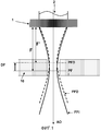
Нагревание оптических систем режущей головки вызывает также смещение DF от точки фокуса луча, связанное с эффектом термического линзирования, также называемым фокусным смещением, который проиллюстрирован на Фиг. 1. При воздействии на линзу 1 ее центр нагревается лазерным лучом 2, коллимированным с большой мощностью и доставляемым по оптической оси (АО), тогда как ее края остаются более холодными. При этом в линзе 1 возникает радиальный градиент температуры. Величина этого градиента тем больше, чем выше плотность мощности, получаемая линзой 1. Этот градиент температуры создает градиент в коэффициенте преломления материала. Это явление, в сочетании с эффектом теплового расширения материала линзы 1, приводит к изменению эффективного радиуса кривизны линзы 1 и изменению ее характеристик фокусирования. Первоначальная фокальная плоскость (PFI) луча, расположенная на расстоянии F от линзы, перемещается вдоль направления распространения луча, становясь ближе к фокусирующей линзе 1, на расстояние F, пока не достигнет смещенной фокальной плоскости (PFD). Затем первоначальный сфокусированный луч (FFI) преобразуется в смещенный сфокусированный луч (FFD), обладающий худшими характеристиками резки.Heating the optical systems of the cutting head also causes a shift DF from the focal point of the beam due to the thermal lensing effect, also called focal shift, which is illustrated in FIG. 1. When exposed to the
Загрязнение поверхности оптических систем в результате воздействия окружающей среды, иначе говоря, пыли, металлических выступов или влажности, и их старение представляют собой факторы, которые увеличивают абсорбцию линз и постепенно усиливают явление нагревания, приводя со временем к увеличению амплитуды фокусного смещения.The surface contamination of optical systems as a result of environmental influences, in other words, dust, metal protrusions or humidity, and their aging are factors that increase the absorption of lenses and gradually enhance the phenomenon of heating, leading to an increase in the amplitude of focal shift over time.
В настоящее время характеристики производительности промышленного способа лазерной резки определяются на основе скорости резки, качества резки - т.е. ровные, гладкие и неискривленные поверхности разреза - и допустимых отклонений рабочих параметров этого способа.Currently, the performance characteristics of the industrial laser cutting method are determined on the basis of cutting speed, cutting quality - i.e. smooth, smooth and non-curved surface of the cut - and the permissible deviations of the operating parameters of this method.
Способ лазерной резки волоконным лазером чувствителен к изменениям положения фокусной точки луча относительно поверхности обрабатываемой детали, особенно когда речь идет о резке очень толстой пластины, а именно от 4 мм и выше. Допустимое отклонения от положения фокусной точки обычно составляет +/-0,5 мм. Если фокусное положение лазерного луча меняется в большую сторону от допустимых отклонений, поддержание оптимального выполнения разреза далее невозможно.The method of laser cutting with a fiber laser is sensitive to changes in the position of the focal point of the beam relative to the surface of the workpiece, especially when it comes to cutting a very thick plate, namely from 4 mm and above. Permissible deviation from the position of the focal point is usually +/- 0.5 mm. If the focal position of the laser beam changes in a larger direction from the permissible deviations, it is further impossible to maintain an optimal cut.
Таким образом, задача заключается в том, чтобы найти новые параметры разреза для компенсации фокусного смещения, или замене оптических систем фокусирующей головки. Отсюда следует снижение продуктивности автоматизированного промышленного способа.Thus, the task is to find new cut parameters to compensate for focal shift, or to replace the optical systems of the focusing head. From here follows a decrease in the productivity of an automated industrial method.
Существенная проблема заключается в том, что если положение фокусной точки меняется во время операции резки, то это приведет к неровному выполнению разреза у разных деталей или даже на разных поверхностях одной и той же детали.A significant problem is that if the position of the focal point changes during the cutting operation, this will lead to uneven execution of the cut in different parts or even on different surfaces of the same part.
Явления, описанные выше, показывают, что длительность выполнения способа резки сильно связана с прочностью оптических систем, обеспечивающих распространение лазерного луча. Поскольку расположение фокусной точки представляет собой важный параметр способа резки волоконным лазером, важно, чтобы фокусное положение луча было как можно более стабильным, и чтобы смещение оставалось в допустимых пределах. Тепловые деформации, которым подвержены оптические элементы, должны быть минимальными при большой мощности во избежание их повреждения. При выборе оптических систем, образующих систему фокусирования головки для лазерной резки, все эти требования должны быть учтены.The phenomena described above show that the duration of the cutting method is strongly related to the strength of the optical systems providing the propagation of the laser beam. Since the location of the focal point is an important parameter of the fiber laser cutting method, it is important that the focal position of the beam is as stable as possible, and that the offset remains within acceptable limits. The thermal deformations to which optical elements are subject must be minimal at high power to avoid damage. When choosing optical systems that form the focusing system of the head for laser cutting, all these requirements must be taken into account.
Кроме этого, проблема также заключается в сложности передачи лазерного луча с высокой яркостью для его использования при резке. Доступные уровни мощности лазерного излучения продолжают увеличиваться, но именно прочность оптических устройств ограничивает уровни мощности, которые могут быть использованы при резке. В действительности лучи с высокой яркостью характеризуются высокими уровнями мощности в сочетании с прекрасными коэффициентами качества, т.е. малыми значениями ВРР, например, порядка 0,33 мм·мрад. Из этого следует очень большая плотность мощности на поверхностях оптических систем фокусирующих головок и увеличение градиентов температуры и тепловых деформаций. Было также обнаружено, что стойкость оптических материалов к повреждению, вызываемому лазерами с высокой яркостью, хуже, чем к повреждению, вызываемому обычными лазерами на основе CO2, поскольку более короткая длина волны у лазеров с высокой яркостью чувствительна сильнее к существующим недостаткам в подложках и поверхностных покрытиях оптических элементов, что может быть причиной избыточного локального нагрева.In addition, the problem also lies in the difficulty of transmitting a high-brightness laser beam for use in cutting. Available laser power levels continue to increase, but it is the strength of optical devices that limits the power levels that can be used in cutting. In reality, high brightness beams are characterized by high power levels combined with excellent quality factors, i.e. small values of VRP, for example, of the order of 0.33 mm · mrad. This implies a very high power density on the surfaces of the optical systems of the focusing heads and an increase in temperature gradients and thermal deformations. It was also found that the resistance of optical materials to damage caused by high brightness lasers is worse than damage caused by conventional CO 2 lasers, since the shorter wavelength of high brightness lasers is more sensitive to existing imperfections in substrates and surface coatings of optical elements, which may cause excessive local heating.
РАСКРЫТИЕ ИЗОБРЕТЕНИЯSUMMARY OF THE INVENTION
Таким образом, задача, которая должна быть решена, заключается в управлении вышеупомянутыми проблемами фокусного смещения и повреждения оптических систем, возникающих при применении твердотельных лазеров, в частности, при использовании волоконного лазера, в особенности волоконного лазера, легированного иттербием, для обеспечения продолжительного выполнения резки, в частности, при применении способа лазерной резки с большой мощностью, т.е. с мощностью, по меньшей мере, 1 кВт.Thus, the problem that must be solved is to manage the aforementioned problems of focal bias and damage to optical systems that arise when using solid-state lasers, in particular when using a fiber laser, in particular a ytterbium-doped fiber laser, to ensure continuous cutting, in particular, when applying the laser cutting method with high power, i.e. with a power of at least 1 kW.
Решение, согласно настоящему изобретению, заключается в фокусирующей лазерный луч головке для лазерной резки металлической детали, содержащей коллимирующую линзу (13) и фокусирующую линзу (14), при этом коллимирующая линза (13) и фокусирующая линза (14) выполнены из ZnS и имеют толщину по краям по меньшей мере 5 мм, и отклоняющее зеркало (15) расположено между коллимирующей линзой (13) и фокусирующей линзой (14) на пути лазерного луча в упомянутой фокусирующей головке таким образом, что лазерный луч имеет угол (α) отражения от 40° до 50° от отклоняющего зеркала (15).The solution according to the present invention consists in a laser beam focusing head for laser cutting of a metal part containing a collimating lens (13) and a focusing lens (14), while the collimating lens (13) and the focusing lens (14) are made of ZnS and have a thickness at least 5 mm along the edges, and a deflecting mirror (15) is located between the collimating lens (13) and the focusing lens (14) in the path of the laser beam in said focusing head so that the laser beam has an angle of reflection (40 °) from 40 ° up to 50 ° from deflecting stool (15).
Настоящее изобретение также относится к установке лазерной резки металлической детали, содержащей:The present invention also relates to a laser cutting apparatus for a metal part comprising:
- твердотельное лазерное устройство, излучающее лазерный луч с длиной волны от 1,06 мкм до 1,10 мкм и мощностью от 0,1 кВт до 25 кВт,- solid-state laser device emitting a laser beam with a wavelength of from 1.06 μm to 1.10 μm and a power of from 0.1 kW to 25 kW,
- фокусирующую лазерный луч головку для лазерной резки металлической согласно первому аспекту изобретения предыдущих пунктов, иa laser beam focusing head for metal laser cutting according to the first aspect of the invention of the preceding paragraphs, and
- передающее волокно, соединяющее твердотельное лазерное устройство и фокусирующую головку так, чтобы подводить лазерный луч, испущенный твердотельным лазерным устройством, к фокусирующей головке.- a transmission fiber connecting the solid-state laser device and the focusing head so as to bring the laser beam emitted by the solid-state laser device to the focusing head.
В зависимости от ситуации установка, согласно настоящему изобретению, может содержать один или более из следующих признаков:Depending on the situation, the installation according to the present invention may contain one or more of the following features:
- твердотельное лазерное устройство представляет собой вид волоконного лазера, предпочтительно волоконный лазер, легированный иттербием;- solid-state laser device is a type of fiber laser, preferably a fiber laser doped with ytterbium;
- твердотельное лазерное устройство излучает лазерный луч с мощностью от 1 кВт до 5 кВт в непрерывном, квазинепрерывном или импульсном режиме, предпочтительно в непрерывном режиме;- a solid-state laser device emits a laser beam with a power of 1 kW to 5 kW in a continuous, quasi-continuous or pulsed mode, preferably in a continuous mode;
- передающее волокно имеет диаметр, который не превышает 150 μм, предпочтительно диаметр 50 мкм или 100 мкм;- the transmitting fiber has a diameter that does not exceed 150 μm, preferably a diameter of 50 μm or 100 μm;
- твердотельное лазерное устройство излучает лазерный луч с ВРР от 1,6 до 4 мм·мрад;- a solid-state laser device emits a laser beam with a VRP from 1.6 to 4 mm · mrad;
- передающее волокно имеет диаметр 50 мкм и ВРР от 1,6 до 2,2 мм·мрад, причем коллимирующая линза имеет фокусное расстояние от 70 мм до 120 мм, а фокусирующая линза имеет фокусное расстояние от 200 мм до 450 мм. Более точно, в случае передающего волокна с диаметром 50 μм, ВРР которого от 1,6 до 2,2 мм·мрад, фокусное расстояние коллимирующей линзы составляет от 70 мм до 120 мм, предпочтительно от 70 мм до 90 мм. Чтобы резать материал, толщина которого строго меньше 10 мм, величина фокусного расстояния фокусирующей линзы преимущественно составляет от 200 мм до 300 мм, предпочтительно от 220 мм до 280 мм, тогда как для резки материала толщиной, выше или равной 10 мм, величина фокусного расстояния фокусирующей линзы преимущественно составляет от 350 мм до 450 мм, предпочтительно от 380 мм до 420 мм;- the transmitting fiber has a diameter of 50 μm and a VRP of 1.6 to 2.2 mm · mrad, the collimating lens has a focal length of 70 mm to 120 mm, and the focusing lens has a focal length of 200 mm to 450 mm. More specifically, in the case of a transmitting fiber with a diameter of 50 μm, the Raman of which is from 1.6 to 2.2 mm · mrad, the focal length of the collimating lens is from 70 mm to 120 mm, preferably from 70 mm to 90 mm. In order to cut a material whose thickness is strictly less than 10 mm, the focal length of the focusing lens is preferably from 200 mm to 300 mm, preferably from 220 mm to 280 mm, while for cutting material with a thickness greater than or equal to 10 mm, the focal length of the focusing lens the lens is preferably 350 mm to 450 mm, preferably 380 mm to 420 mm;
- передающее волокно (FDC) имеет диаметр 100 μм и ВРР от 2,6 до 4 мм·мрад, причем коллимирующая линза имеет фокусное расстояние от 130 до 180 мм, а фокусирующая линза имеет фокусное расстояние от 200 до 450 мм. Более точно, в случае передающего волокна с диаметром 100 мкм, ВРР которого от 2,6 и 4 мм·мрад, фокусное расстояние коллимирующей линзы составляет от 130 мм до 180 мм, предпочтительно от 140 мм до 180 мм. Чтобы резать материал, толщина которого строго меньше 10 мм, величина фокусного расстояния фокусирующей линзы преимущественно составляет от 200 мм до 300 мм, предпочтительно от 220 мм до 280 мм, тогда как для резки материала толщиной выше или равной 10 мм, величина фокусного расстояния фокусирующей линзы преимущественно составляет от 350 мм до 450 мм, предпочтительно от 380 мм до 420 мм;- the transmitting fiber (FDC) has a diameter of 100 μm and a BPP of 2.6 to 4 mm · mrad, the collimating lens has a focal length of 130 to 180 mm, and the focusing lens has a focal length of 200 to 450 mm. More precisely, in the case of a transmitting fiber with a diameter of 100 μm, the VRP of which is from 2.6 and 4 mm · mrad, the focal length of the collimating lens is from 130 mm to 180 mm, preferably from 140 mm to 180 mm. In order to cut a material whose thickness is strictly less than 10 mm, the focal length of the focusing lens is preferably from 200 mm to 300 mm, preferably from 220 mm to 280 mm, while for cutting material with a thickness greater than or equal to 10 mm, the focal length of the focusing lens preferably between 350 mm and 450 mm, preferably between 380 mm and 420 mm;
- фокусирующая линза имеет фокусное расстояние от 200 мм и 450 мм.- the focusing lens has a focal length of 200 mm and 450 mm.
Кроме этого, настоящее изобретение также относится к способу лазерной резки металлической детали, в котором применяют установку лазерной резки согласно настоящему изобретению.In addition, the present invention also relates to a laser cutting method for a metal part in which a laser cutting apparatus according to the present invention is used.
КРАТКОЕ ОПИСАНИЕ ЧЕРТЕЖЕЙBRIEF DESCRIPTION OF THE DRAWINGS
Настоящее изобретение, которое, в частности, раскрывает определенную оптическую конфигурацию, используемую в режущей головке волоконного лазера, будет более понятно при рассмотрении нижеследующего детального описания и прилагаемых чертежей, на которых:The present invention, which, in particular, discloses a specific optical configuration used in a cutting head of a fiber laser, will be more clear when considering the following detailed description and the accompanying drawings, in which:
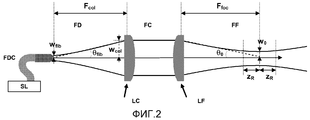
Фиг. 2 показывает основную схему обычной оптической системы для режущей головки и параметры характеристик лазерного луча, распространяющегося через оптическую систему,FIG. 2 shows a basic diagram of a conventional optical system for a cutting head and characteristics of the characteristics of a laser beam propagating through an optical system,
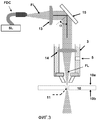
Фиг 3 схематично показывает принцип действия установки и способа лазерной резки согласно настоящему изобретению,Fig 3 schematically shows the principle of operation of the installation and method of laser cutting according to the present invention,
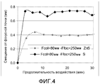
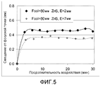
Фиг. 4 показывает сравнение изменений положения фокусной точки луча при лазерном излучении из системы линз, выполненных из ZnS, и системы линз, выполненных из плавленого кремния (Si), и Фиг. 5 показывает сравнение изменений положения фокусной точки луча, сфокусированного системой линз из ZnS, включающей в себя коллимирующую линзу с толщиной по краям 2 мм и коллимирующую линзу с толщиной по краям 7 мм.FIG. 4 shows a comparison of changes in the position of the focal point of the beam due to laser radiation from a lens system made of ZnS and a lens system made from fused silicon (Si), and FIG. 5 shows a comparison of changes in the position of the focal point of a beam focused by a ZnS lens system, including a collimating lens with a thickness of 2 mm at the edges and a collimating lens with a thickness of 7 mm at the edges.
ОСУЩЕСТВЛЕНИЕ ИЗОБРЕТЕНИЯDETAILED DESCRIPTION OF THE INVENTION
Установка резки, согласно настоящему изобретению, содержит твердотельный лазерный источник SL, оборудованный, по меньшей мере, одним оптическим волокном FDC, передающим луч, и фокусирующей головкой 3, называемой также режущей головкой, для перемещения и фокусирования лазерного луча FL на подлежащую разрезанию деталь 10 или в нее. Особенности и диапазон функционирования установки объясняются далее и проиллюстрированы на Фиг. 3.The cutting apparatus according to the present invention comprises a solid-state laser source SL equipped with at least one FDC optical fiber transmitting a beam and a focusing
Режущая головка 3 содержит, как известно, оптические устройства для коллимации, перенаправления и фокусирования лазерного луча.The cutting
Кроме этого, лазерный луч излучается твердотельным лазерным устройством или генератором, предпочтительно волоконным лазером с примесью иттербия (Yb). В этом лазерном устройстве, действие лазера, а именно явление усиления света, служащее для генерирования лазерного излучения, достигается при помощи усиливающей среды, предпочтительно накачиваемой лазерными диодами и образованной одним или обычно несколькими легированными оптическими волокнами, предпочтительно кремниевыми волокнами с примесью иттербия.In addition, the laser beam is emitted by a solid-state laser device or generator, preferably a ytterbium (Yb) doped fiber laser. In this laser device, the laser action, namely the phenomenon of light amplification, which serves to generate laser radiation, is achieved using an amplifying medium, preferably pumped by laser diodes and formed by one or usually several doped optical fibers, preferably silicon fibers with ytterbium impurity.
Длина волны излучения, исходящего на выходе из лазерного устройства, составляет от 1,06 мкм до 1,10 мкм, а мощность лазера находится между 0,1 кВт и 25 кВт, обычно между 1 кВт и 5 кВт.The wavelength of the radiation emanating from the output of the laser device is from 1.06 μm to 1.10 μm, and the laser power is between 0.1 kW and 25 kW, usually between 1 kW and 5 kW.
Лазер может функционировать в непрерывном, квазинепрерывном или импульсном режиме, но, согласно настоящему изобретению, предпочтительно, чтобы лазер работал в непрерывном режиме, так как речь идет о самом сильном режиме излучения для оптики режущей головки.The laser may operate in a continuous, quasi-continuous or pulsed mode, but according to the present invention, it is preferable that the laser operate in a continuous mode, since this is the strongest radiation mode for the optics of the cutting head.
Луч, генерируемый твердотельным лазерным источником, излучается и передается до фокусирующей головки посредством, по меньшей мере, одного оптического передающего волокна, выполненного из нелегированного кремния, диаметром менее 150 мкм, например, равным 50 мкм или 100 мкм.A beam generated by a solid-state laser source is emitted and transmitted to the focusing head by means of at least one optical transmitting fiber made of undoped silicon with a diameter of less than 150 μm, for example, equal to 50 μm or 100 μm.
В целом, использование лазерного источника с большой яркостью, такого как волоконный лазер, позволяет генерировать лучи большой мощности с прекрасными коэффициентами качества.In general, the use of a high brightness laser source, such as a fiber laser, allows the generation of high power beams with excellent quality factors.
Степень качества лазерного луча измеряется по его коэффициенту качества или параметру качества луча (ВРР). ВРР определяется характеристиками лазерного источника SL и диаметром передающего волокна FDC. Он выражается как произведение радиуса w0 в сужении сфокусированного лазерного луча на половину угла расходимости θ0, как показано на Фиг. 2. ВРР также определяется как произведение радиуса wfib оптического передающего волокна, испускающего лазерный луч, на половину угла расходимости θfib луча на выходе из волокна. Таким образом, для волокна 50 мкм ВРР луча обычно составляет от 1,6 до 2 мм·мрад, тогда как для волокна 100 мкм, ВРР обычно составляет от 2,7 до 4 мм·мрад.The degree of quality of a laser beam is measured by its quality factor or beam quality parameter (VRP). VRP is determined by the characteristics of the SL laser source and the diameter of the transmitting fiber FDC. It is expressed as the product of radius w 0 in narrowing the focused laser beam by half the divergence angle θ 0 , as shown in FIG. 2. VRP is also defined as the product of the radius w fib of the optical transmitting fiber emitting the laser beam by half the divergence angle θ fib of the beam at the exit from the fiber. Thus, for a fiber of 50 μm, the VRP of the beam is usually from 1.6 to 2 mm · mrad, while for a fiber of 100 μm, the BPP is usually from 2.7 to 4 mm · mrad.
Как показано на Фиг. 2, система фокусирования лазерной режущей головки состоит, последовательно в направлении распространения лазерного луча, по меньшей мере, из одной коллимирующей линзы LC, позволяющей получить коллимированный луч FC на основе расходящегося луча FD, и, по меньшей мере, одну фокусирующую линзу LF, позволяющую получить сфокусированный луч FF и сконцентрировать энергию лазера на разрезаемой детали. Фокусные расстояния коллимирующей линзы и фокусирующей линзы выбираются таким образом, чтобы получить фокальное пятно с диаметром, обеспечиваемым необходимую для резки детали плотность мощности.As shown in FIG. 2, the focusing system of the laser cutting head consists, sequentially in the direction of propagation of the laser beam, of at least one collimating lens LC, allowing to obtain a collimated FC beam based on the diverging beam FD, and at least one focusing lens LF, allowing to obtain focused FF beam and concentrate laser energy on the cut part. The focal lengths of the collimating lens and the focusing lens are selected so as to obtain a focal spot with a diameter that provides the power density necessary for cutting the part.
Диаметр 2w0 луча в фокальной плоскости определяется как произведение диаметра 2wfib волокна на оптическое увеличение G системы фокусирования, и выражается следующим образом:The diameter 2w 0 of the beam in the focal plane is defined as the product of the diameter 2w of the fib fiber and the optical magnification G of the focusing system, and is expressed as follows:
![]()
![]()
где - G определяется отношением фокусного расстояния Ffoc фокусирующей линзы FC к фокусному расстоянию Fcol коллимирующей линзы LC; иwhere - G is determined by the ratio of the focal length F foc of the focusing lens FC to the focal length F col of the collimating lens LC; and
- w0 and wfib являются характерными радиусами луча в фокальной плоскости и волокна, соответственно. Под характерным радиусом w понимается расстояние от оптической оси, где интенсивность падает как 1/e2 (примерно 13.5%) от его максимального значения, что означает, что 86,5% от энергии луча заключено в диске радиусом w. Все параметры луча определяются согласно этому критерию.- w 0 and w fib are the characteristic radii of the beam in the focal plane and the fibers, respectively. By the characteristic radius w is meant the distance from the optical axis, where the intensity drops as 1 / e 2 (approximately 13.5%) from its maximum value, which means that 86.5% of the beam energy is enclosed in a disk of radius w. All beam parameters are determined according to this criterion.
Радиус луча, излучаемого коллимирующей и фокусирующей оптическими системами, определяется следующим отношением:The radius of the beam emitted by the collimating and focusing optical systems is determined by the following relation:
![]()
![]()
![]()
![]()
Половина угла расходимости θfib луча, испущенного передающим волокном, выводится из значения ВРР сфокусированного луча через следующее соотношение:Half of the divergence angle θ fib of the beam emitted by the transmitting fiber is derived from the value of the SRP of the focused beam through the following relationship:
![]()
![]()
Средняя плотность мощности на единицу поверхности, также называемая плотностью мощности (DP), излучаемой оптическими системами выражается в кВт/см2 и определяется следующим образом:The average power density per unit surface, also called the power density (DP) emitted by optical systems, is expressed in kW / cm 2 and is defined as follows:
![]()
![]()
где Plas является полной энергией излучения, испускаемой лазерным источником, a wcol представляет собой характерный радиус луча, воздействующего на оптическую систему. where P las is the total energy of the radiation emitted by the laser source, aw col represents the characteristic radius of the beam acting on the optical system.
Таким образом, понятны проблемы, возникающие при использовании лазерного генератора высокой яркости, такого как волоконный лазер, а именно:Thus, the problems that arise when using a high brightness laser generator, such as a fiber laser, are understood, namely:
- такой тип источника характеризуется слабым ВРР и, таким образом, лучами, имеющими более слабую расходимость θfib на выходе волокна. Этот параметр соответствует скорости распространения в удаленные поля луча, испущенного передающим волокном, и определяет диаметр луча на оптике системы. При одном и том же коллимирующем фокусном расстоянии луч высшего качества и, следовательно, более слабой расходимости, имеет меньший диаметр 2wcol на коллимирующей линзе. Отсюда следует увеличение DP. В рекомендательных целях в приведенной ниже таблице 1 даны обычные сравнительные характеристики луча для различных лазеров, а также плотности получаемой мощности на оптических системах для мощности 2 кВт и фокусного расстояния коллимирующей линзы, равного 100 мм;- this type of source is characterized by weak SRS and, thus, by rays having a weaker divergence θ fib at the fiber exit. This parameter corresponds to the speed of propagation into remote fields of the beam emitted by the transmitting fiber, and determines the diameter of the beam on the optics of the system. At the same collimating focal length, a ray of superior quality and, therefore, weaker divergence, has a smaller diameter of 2w col on the collimating lens. Hence the increase in DP. For advisory purposes, Table 1 below shows the usual comparative beam characteristics for various lasers, as well as the power density obtained on optical systems for a power of 2 kW and a focal length of a collimating lens of 100 mm;
- при таком же оптическом увеличении лазерный луч с меньшим ВРР фокусируется с одним и тем же фокусным диаметром и имеет меньшую расходимость θ0. Его длина Релея zR=w0/θ0 является большей. Между тем, смещение фокусной точки, вызванное нагреванием системы фокусирования с большой мощностью, пропорциональна zR.- at the same optical magnification, a laser beam with a smaller VRS is focused with the same focal diameter and has a smaller divergence θ 0 . Its Rayleigh length z R = w 0 / θ 0 is greater. Meanwhile, the shift of the focal point caused by the heating of the focusing system with high power is proportional to z R.


Из таблицы видно, что плотность мощности на линзах увеличивается с ростом качества луча. Амплитуда градиента температуры, устанавливающаяся в оптических системах под воздействием лазерного излучения, увеличивается с плотностью мощности, подаваемой на оптические системы. Таким образом, во избежание проблем фокусного смещения и повреждения лазером предпочтительно работать с оптическими системами, имеющими лучшие возможные температурные характеристики.The table shows that the power density on the lens increases with increasing beam quality. The amplitude of the temperature gradient, which is established in optical systems under the influence of laser radiation, increases with the power density supplied to the optical systems. Thus, in order to avoid problems of focal bias and laser damage, it is preferable to work with optical systems having the best possible temperature characteristics.
С этой целью оптическая система, согласно настоящему изобретению, объединяет определенные свойства, описанные ниже, как показано на схеме на Фиг. 3.To this end, the optical system according to the present invention combines certain properties described below, as shown in the diagram of FIG. 3.
Режущая головка 3 состоит из оптических устройств, работающих на передачу, т.е. здесь линзы 13, 14 служат для операций коллимации (на 13) и фокусирования (на 14) луча FL лазера, исходящего из передающего волокна и генерируемого твердотельным лазерным источником SL.The cutting
Предпочтительно используют сульфид цинка (ZnS) как подложку для коллимирующей линзы 13 и фокусирующей линзы 14. Это связано с тем, что амплитуда градиента температуры, появившегося в линзах под воздействием лазерного излучения, обратно пропорциональна теплопроводности материалов, составляющих линзу. Так, теплопроводность ZnS (0,272 Вт/см/°C) приблизительно в 20 раз больше теплопроводности плавленого кремния (0,0138 ВТ/см/°C). Эта повышенная теплопроводность увеличивает способность ZnS выводить тепло и позволяет уменьшить амплитуду градиентов температуры и тепловых деформаций, вызванных в линзе ограниченным излучением с большой мощностью.Zinc sulfide (ZnS) is preferably used as a substrate for the
Упомянутые оптическое коллимирующее устройство 13 и оптическое фокусирующее устройство 14 могут быть выбраны среди различных типов имеющихся линз. Линзы являются предпочтительно синглетами для ограничения количества оптических поверхностей системы фокусирования и минимизации рисков повреждений. Может быть использована различная геометрия линз, например, плосковыпуклая, бивыпуклая или выпукло-вогнутая форма. Предпочтительно, используются плоско-выпуклые линзы. Все оптические поверхности предпочтительно обладают антиотражающими покрытиями, не отражающими при длине волны лазера.Mentioned
Линзы режущей головки помещают в термически регулируемый держатель. Вода, циркулирующая в держателе, обеспечивает охлаждение посредством косвенного контакта с линзами. Температура воды поддерживается от 19°C до 25°C.The lenses of the cutting head are placed in a thermally adjustable holder. The water circulating in the holder provides cooling through indirect contact with the lenses. The water temperature is maintained between 19 ° C and 25 ° C.
Толщина и диаметр линз 13 и 14 имеют одинаковое влияние на их тепловые характеристики. Чем больше размеры линз, тем лучше диссипация тепла через более холодные периферийные зоны и меньше градиенты температуры. В обычных режущих головках используют линзы с большой толщиной, т.е. с толщиной по краям, по меньшей мере, 5 мм, только для выполнения операции фокусирования. Это связано с тем, что вспомогательный газ выбрасывается непосредственно после фокусирующей линзы, тем самым подвергая ее сильному давлению. Фокусирующая линза должна, таким образом, быть толстой, чтобы обладать надлежащим механическим сопротивлением. В рамках настоящего изобретения, для уменьшения явления фокусного смещения используют толстые линзы как для коллимации луча, так и для его фокусирования. В отличие от обычной головки, режущая головка 3 состоит, таким образом, из линз, толщина которых по краям равна, по меньшей мере, 5 мм, предпочтительно от 6 до 8 мм. Также, поскольку большая толщина улучшает тепловые характеристики, оптические системы с большим диаметром лучше выводят тепло по краям. Каким бы ни был размер луча, воздействующего на оптическую систему режущей головки 3, в ней используются линзы с диаметром от 35 до 55 мм.The thickness and diameter of the
В режущей головке 3 отражающий компонент 15 расположен на пути 10 лазерного луча между коллимирующей линзой 13 и фокусирующей линзой 14. Этот компонент представляет собой плоское зеркало и не изменяет параметры распространения луча. Подложка зеркала выполнена из плавленого кремния.In the cutting
По меньшей мере, одна поверхность зеркала покрыта отражающим слоем. Этот слой образован тонкими оптическими слоями и отражает свет с длиной волны режущего лазерного луча, а также с длиной волны от 630 нм до 670 нм. Покрытие является, тем не менее, прозрачным для видимой и инфракрасной области спектра, включая длину волны системы освещения, например, для лазерного диода. Таким образом, можно присоединить устройство управления способом (типа камеры или фотодиода) позади зеркала. Оно обеспечивает отражение лазерного луча под углом α отражения от 40° до 50°, предпочтительно 45°. Толщина зеркала составляет от 3 мм до 15 мм, предпочтительно от 8 до 12 мм. Это зеркало позволяет прежде всего уменьшить вертикальные габариты головки, чтобы усилить механическую прочность. Более того, при такой конфигурации передающее волокно удерживается горизонтально, что уменьшает риск проникновения пыли во время операций монтажа и демонтажа волокна или коллиматора. И, наконец, интегрирование отражающего компонента на пути луча позволяет компенсировать фокусное смещение, вызванное линзами. В действительности продольное перемещение фокусной точки, вызванное отражающим компонентом, имеет место в направлении, противоположном фокусному смещению, вызванному передающим компонентом.At least one surface of the mirror is coated with a reflective layer. This layer is formed by thin optical layers and reflects light with a wavelength of the cutting laser beam, as well as with a wavelength of 630 nm to 670 nm. The coating is, however, transparent to the visible and infrared spectral region, including the wavelength of the lighting system, for example, a laser diode. Thus, it is possible to attach a method control device (such as a camera or a photodiode) behind the mirror. It provides reflection of the laser beam at an angle of reflection α from 40 ° to 50 °, preferably 45 °. The thickness of the mirror is from 3 mm to 15 mm, preferably from 8 to 12 mm. This mirror allows, first of all, to reduce the vertical dimensions of the head in order to enhance mechanical strength. Moreover, with this configuration, the transmitting fiber is held horizontally, which reduces the risk of dust penetration during installation and removal of the fiber or collimator. And finally, the integration of the reflecting component in the path of the beam compensates for the focal shift caused by the lenses. In fact, the longitudinal movement of the focal point caused by the reflecting component takes place in a direction opposite to the focal offset caused by the transmitting component.
Линзы режущей головки 3 также характеризуются определенными фокусными расстояниями, адаптированными к ВРР используемого передающего волокна. Эти фокусные расстояния необходимы для получения фокального пятна диаметром 2w0, подходящего для резки обрабатываемого материала. Для передающего волокна диаметром 50 μм ВРР луча обычно составляет от 1,6 до 2,2 мм·мрад. Для этого волокна фокусное расстояние коллимирующей линзы составляет от 70 до 120 мм, предпочтительно от 70 до 90 мм. Выбор фокусного расстояния коллимирующей линзы определяет выбор фокусного расстояния фокусирующей линзы в зависимости от желаемого оптического увеличения для резки толщи обрабатываемого материала.The lenses of the cutting
Для материалов, толщина которых строго меньше 10 мм, фокусное расстояние фокусирующей линзы составляет от 200 до 300 мм, предпочтительно от 220 до 280 мм. Для материалов, имеющих толщину больше или равную 10 мм, фокусное расстояние фокусирующей линзы составляет от 350 мм до 450 мм, предпочтительно от 380 мм до 420 мм. For materials whose thickness is strictly less than 10 mm, the focal length of the focusing lens is 200 to 300 mm, preferably 220 to 280 mm. For materials having a thickness greater than or equal to 10 mm, the focal length of the focusing lens is from 350 mm to 450 mm, preferably from 380 mm to 420 mm.
Для передающего волокна диаметром 100 мкм ВРР луча обычно составляет от 2,6 до 4 мм·мрад. Для этого волокна фокусное расстояние коллимирующей линзы составляет от 130 мм до 180 мм, предпочтительно от 140 мм до 180 мм. Для материалов с толщиной строго меньше 10 мм фокусное расстояние фокусирующей линзы составляет от 200 мм до 300 мм, предпочтительно от 220 мм до 280 мм. Для материалов, имеющих толщину большую или равную 10 мм, фокусное расстояние фокусирующей линзы составляет от 350 до 450 мм, предпочтительно от 380 до 420 мм.For a transmitting fiber with a diameter of 100 μm, the Raman beam usually ranges from 2.6 to 4 mm · mrad. For this fiber, the focal length of the collimating lens is from 130 mm to 180 mm, preferably from 140 mm to 180 mm. For materials with a thickness strictly less than 10 mm, the focal length of the focusing lens is from 200 mm to 300 mm, preferably from 220 mm to 280 mm. For materials having a thickness greater than or equal to 10 mm, the focal length of the focusing lens is 350 to 450 mm, preferably 380 to 420 mm.
В фокусирующую головку 3 подается вспомогательный газ через вход 5 для газа, выполненный в стенке указанной фокусирующей головки 3, через которую газ или газовая смесь поступает под давлением от источника газа, например, от одного или более газовых баллонов, емкости хранения или от одной или более газовых линий, таких как газовая распределительная система, и вводится на вход сопла 4 и выводится через это сопло 4 в направлении детали 30, разрезаемой лазерным лучом.An auxiliary gas is supplied to the focusing
Вспомогательный газ служит для удаления расплавленного металла из прорези 12 разреза, полученного плавлением металла посредством лазерного луча FL, который фокусируется в положении 11 относительно поверхности разрезаемой детали 10.The auxiliary gas serves to remove molten metal from the slot 12 of the cut obtained by melting the metal by means of a laser beam FL, which focuses at
Выбор газа осуществляется в зависимости от характеристик разрезаемого материала, в частности, от его состава, типа и его толщины. Например, для резки стали может быть использован воздух, кислород, смесь азота/кислород или гелия/азота, тогда как азот, смеси азота/водорода или аргона/азота могут использоваться для резки алюминия или нержавеющей стали. The choice of gas is carried out depending on the characteristics of the material being cut, in particular, on its composition, type and thickness. For example, air, oxygen, a mixture of nitrogen / oxygen or helium / nitrogen can be used to cut steel, while nitrogen, a mixture of nitrogen / hydrogen or argon / nitrogen can be used to cut aluminum or stainless steel.
В действительности, разрезаемая лазером деталь 10 может быть образована из различных металлических материалов, таких как сталь, нержавеющая сталь, мягкая сталь или легкие сплавы, такие как алюминий и его сплавы, даже титан и его сплавы, имеющие обычно толщину от 0,1 мм до 30 мм.In fact, the laser-
При осуществлении способа резки лазерный луч может фокусироваться (на 11) в толще или на одной из поверхностей детали 10, или вблизи нее, т.е. снаружи и в нескольких мм сверху или снизу от ее верхней поверхности 10а, или нижней поверхности 10b, или на поверхности 10а, или нижней поверхности 10b. Предпочтительно, положение 11 фокусной точки находится на расстоянии 5 мм сверху от верхней поверхности 10a и 5 мм снизу от нижней поверхности 10b детали 10.When implementing the cutting method, the laser beam can be focused (by 11) in the thickness or on one of the surfaces of the
Благодаря настоящему изобретению положение фокусирования лазерного луча стабильно удерживается в ходе процесса резки, так можно избежать или минимизировать любые фокусные смещения и любые повреждения оптической системы, что гарантирует по существу постоянные рабочие характеристики в течение всей операции лазерной резки.Thanks to the present invention, the focusing position of the laser beam is stably held during the cutting process, so that any focal displacements and any damage to the optical system can be avoided or minimized, which ensures essentially constant performance during the entire laser cutting operation.
Предпочтительнее использовать одну или более линз из ZnS, чем из плавленого кремния, что было продемонстрировано при сравнении фокусного смещения, вызываемого воздействием высокой мощности на эти два типа линз.It is preferable to use one or more ZnS lenses than fused silicon, which was demonstrated by comparing the focal shift caused by the high power effect on these two types of lenses.
Для этого сравнивались две оптические системы, каждая из которых состоит из одной коллимирующей линзы с фокусным расстоянием 80 мм и одной фокусирующей линзы с 250 мм. Одна система содержала линзы из ZnS, а другая - из плавленого кремния.For this, two optical systems were compared, each of which consists of one collimating lens with a focal length of 80 mm and one focusing lens with 250 mm. One system contained ZnS lenses and the other a fused silicon lens.
Каустика лазерного луча, сфокусированного каждой системой, регистрировалась при помощи анализатора луча. Это устройство измеряет радиус луча, для которого 86% мощности лазера содержится в диске этого радиуса в пределах последовательных плоскостей распространения, находящихся на расстоянии приблизительно 10 мм по обеим сторонам от сужения сфокусированного луча.The caustics of the laser beam focused by each system were recorded using a beam analyzer. This device measures the radius of the beam for which 86% of the laser power is contained in a disk of this radius within successive propagation planes that are approximately 10 mm apart on both sides of the narrowing of the focused beam.
На основе зарегистрированной каустики можно определить положение фокальной плоскости лазерного луча вдоль направления его распространения. Изменение положения фокальной плоскости во время длительного воздействия фокусирующей оптической системы может происходить при выполнении серий анализа луча.Based on the registered caustic, one can determine the position of the focal plane of the laser beam along the direction of its propagation. A change in the position of the focal plane during prolonged exposure to a focusing optical system can occur when performing series of beam analyzes.
Во время этих испытаний каждая оптическая система подвергалась воздействию приблизительно в течение 30 минут. При изучаемой оптической конфигурации луч имел на линзе диаметр 9,6 мм, что приводит к плотности мощности порядка от 2,8 кВт/см2 при 2 кВт.During these tests, each optical system was exposed for approximately 30 minutes. In the studied optical configuration, the beam had a diameter of 9.6 mm on the lens, which leads to a power density of the order of 2.8 kW / cm 2 at 2 kW.
На Фиг. 4 сравнивается изменение положения фокусной точки луча, сфокусированного системой линз из ZnS или из плавленого кремния (S). Для каждой кривой первая точка соответствует положению, зарегистрированному при первом анализе луча, выполненном при 200 Вт. При этой мощности фокусное смещение, вызванное эффектом термического линзирования, ничтожно. Можно считать, что измеренное положение соответствует положению, в котором сразу же находится фокусная точка луча после включения лазера. Фокусное смещение потом измеряется относительно именно этого положения. Следовательно, эта первая точка на кривых соответствует смещению от нулевой фокусной точки.In FIG. 4 compares the change in position of the focal point of a beam focused by a lens system made of ZnS or fused silicon (S). For each curve, the first point corresponds to the position recorded during the first beam analysis performed at 200 W. At this power, the focal shift caused by the thermal lensing effect is negligible. We can assume that the measured position corresponds to the position in which the focal point of the beam is immediately located after the laser is turned on. The focal shift is then measured relative to this particular position. Therefore, this first point on the curves corresponds to an offset from the zero focal point.
На Фиг. 5 показано, что продольное смещение от фокусной точки для системы из плавленого кремния (Si) больше, чем смещение для системы из ZnS. Использование ZnS позволяет, таким образом, уменьшить амплитуду смещения фокусной точки при излучении оптической системы с сильной мощностью.In FIG. 5 shows that the longitudinal displacement from the focal point for a fused silicon (Si) system is greater than the displacement for a ZnS system. The use of ZnS allows, therefore, to reduce the amplitude of the shift of the focal point when emitting an optical system with strong power.
Эффект изменения толщины по краям коллимирующей линзы также был изучен. С этой целью сравнивались амплитуда смещения фокусной точки, полученной при системе линз ZnS, включающей в себя коллимирующую линзу с толщиной Е по краям, равной 2 мм, или системе, включающей в себя коллимирующую линзу с толщиной Е по краям, равной 7 мм.The effect of thickness variation at the edges of a collimating lens has also been studied. To this end, we compared the amplitude of the shift of the focal point obtained with the ZnS lens system, which includes a collimating lens with a thickness E at the edges equal to 2 mm, or a system that includes a collimating lens with a thickness E at the edges equal to 7 mm.
На Фиг. 5 сравнивается изменение положение фокусной точки луча, сфокусированного обеими системами в соответствии описанным выше способом.In FIG. 5 compares the change in position of the focal point of the beam focused by both systems in accordance with the method described above.
Видно, что продольное смещение фокусной точки больше, так как коллимирующая линза тоньше.It is seen that the longitudinal shift of the focal point is larger, since the collimating lens is thinner.
Сочетание оптических устройств, согласно настоящему изобретению, позволяет гарантировать продолжительность выполнения способа лазерной резки, в частности в случае способа лазерной резки при помощи твердотельного лазера, в частности волоконного лазера, благодаря управлению амплитудой фокусного смещения и проблемами повреждения оптических систем. The combination of optical devices according to the present invention allows to guarantee the duration of the laser cutting method, in particular in the case of a laser cutting method using a solid-state laser, in particular a fiber laser, by controlling the focal bias amplitude and damage problems of the optical systems.
Claims (13)
- коллимирующая линза (13) и фокусирующая линза (14) выполнены из ZnS и имеют толщину по краям по меньшей мере 5 мм, и
- отклоняющее зеркало (15), расположенное между коллимирующей линзой (13) и фокусирующей линзой (14) на пути лазерного луча в упомянутой фокусирующей головке таким образом, что лазерный луч имеет угол (α) отражения от 40° до 50° от отклоняющего зеркала (15).1. A laser beam focusing head for laser cutting of a metal part, comprising a collimating lens (13) and a focusing lens (14), characterized in that:
the collimating lens (13) and the focusing lens (14) are made of ZnS and have a thickness at the edges of at least 5 mm, and
- a deflecting mirror (15) located between the collimating lens (13) and the focusing lens (14) in the path of the laser beam in said focusing head so that the laser beam has a reflection angle (α) from 40 ° to 50 ° from the deflecting mirror ( fifteen).
- твердотельное лазерное устройство (SL), излучающее лазерный луч с длиной волны от 1,06 мкм до 1,10 мкм и мощностью от 0,1 кВт до 25 кВт,
- фокусирующую лазерный луч головку для лазерной резки металлической детали по одному из пп.1-4, и
- передающее волокно (FDC), соединяющее твердотельное лазерное устройство (SL) и фокусирующую головку так, чтобы подводить луч лазера, излучаемый твердотельным лазерным устройством (SL), к фокусирующей головке.5. Installation for laser cutting of metal parts, containing:
- solid-state laser device (SL) emitting a laser beam with a wavelength of 1.06 μm to 1.10 μm and a power of 0.1 kW to 25 kW,
- focusing the laser beam head for laser cutting of a metal part according to one of claims 1 to 4, and
- a transmitting fiber (FDC) connecting the solid-state laser device (SL) and the focusing head so as to bring the laser beam emitted by the solid-state laser device (SL) to the focusing head.
Applications Claiming Priority (3)
| Application Number | Priority Date | Filing Date | Title |
|---|---|---|---|
| FR0955949A FR2949618B1 (en) | 2009-09-01 | 2009-09-01 | LASER FOCUSING HEAD FOR SOLID LASER INSTALLATION |
| FR0955949 | 2009-09-01 | ||
| PCT/FR2010/051723 WO2011027065A1 (en) | 2009-09-01 | 2010-08-17 | LASER-FOCUSING HEAD WITH ZnS LENSES HAVING A PERIPHERAL THICKNESS OF AT LEAST 5 MM AND LASER CUTTING UNIT AND METHOD USING ONE SUCH FOCUSING HEAD |
Publications (2)
| Publication Number | Publication Date |
|---|---|
| RU2012112398A RU2012112398A (en) | 2013-10-10 |
| RU2553152C2 true RU2553152C2 (en) | 2015-06-10 |
Family
ID=42105843
Family Applications (1)
| Application Number | Title | Priority Date | Filing Date |
|---|---|---|---|
| RU2012112398/02A RU2553152C2 (en) | 2009-09-01 | 2010-08-17 | LASER-FOCUSING HEAD WITH ZnS LENSES HAVING PERIPHERAL THICKNESS OF AT LEAST 5 mm AND LASER CUTTING APPARATUS AND METHOD USING ONE SUCH FOCUSING HEAD |
Country Status (13)
| Country | Link |
|---|---|
| US (1) | US20120154922A1 (en) |
| EP (1) | EP2473315B1 (en) |
| JP (1) | JP2013503751A (en) |
| CN (1) | CN102481665B (en) |
| BR (1) | BR112012004680A2 (en) |
| DK (1) | DK2473315T3 (en) |
| ES (1) | ES2457231T3 (en) |
| FR (1) | FR2949618B1 (en) |
| IN (1) | IN2012DN00926A (en) |
| PL (1) | PL2473315T3 (en) |
| PT (1) | PT2473315E (en) |
| RU (1) | RU2553152C2 (en) |
| WO (1) | WO2011027065A1 (en) |
Cited By (1)
| Publication number | Priority date | Publication date | Assignee | Title |
|---|---|---|---|---|
| RU2760443C1 (en) * | 2020-12-07 | 2021-11-25 | Общество с Ограниченной Ответственностью Научно Исследовательский Центр «Астрофизика» | Focusing apparatus for laser processing |
Families Citing this family (19)
| Publication number | Priority date | Publication date | Assignee | Title |
|---|---|---|---|---|
| JP5642493B2 (en) * | 2010-10-15 | 2014-12-17 | 三菱重工業株式会社 | Laser cutting apparatus and laser cutting method |
| JP5766423B2 (en) * | 2010-10-15 | 2015-08-19 | 三菱重工業株式会社 | Laser cutting apparatus and laser cutting method |
| RU2607500C2 (en) | 2010-12-16 | 2017-01-10 | Бистроник Лейзер Аг | Device for laser processing and method for laser processing, containing singlet lens for focusing |
| US8881553B2 (en) * | 2011-06-01 | 2014-11-11 | US Conec, Ltd | Assembly for precision datum alignment and method of use |
| DE102013102442B4 (en) * | 2013-03-12 | 2014-11-27 | Highyag Lasertechnologie Gmbh | Optical device for beam shaping |
| JP5805256B1 (en) * | 2014-04-07 | 2015-11-04 | ハイヤグ レーザーテクノロジー ゲーエムベーハーHIGHYAG Lasertechnologie GmbH | Optical devices for beam shaping |
| US9678281B2 (en) | 2014-04-25 | 2017-06-13 | US Conec, Ltd | Apparatus for and method of terminating a multi-fiber ferrule |
| CN103962731B (en) * | 2014-04-30 | 2016-04-27 | 武汉锐科光纤激光器技术有限责任公司 | The method of the thick metal material of optical-fiber laser negative pressure cutting more than 8mm |
| JP5919356B2 (en) * | 2014-10-15 | 2016-05-18 | 株式会社アマダホールディングス | Sheet metal processing method using laser light and laser processing apparatus for executing the same |
| JP6025917B1 (en) * | 2015-06-10 | 2016-11-16 | 株式会社アマダホールディングス | Laser cutting method |
| IT201600070259A1 (en) * | 2016-07-06 | 2018-01-06 | Adige Spa | Process of laser processing of a metal material with control of the position of the optical axis of the laser with respect to a flow of assistance gas, as well as a machine and computer program for carrying out such a process. |
| JP6980025B2 (en) * | 2017-10-17 | 2021-12-15 | 三菱電機株式会社 | Laser welding method and laser processing equipment |
| GB201801796D0 (en) * | 2018-02-02 | 2018-03-21 | Spi Lasers Uk Ltd | Apparatus and method for laser processing a material |
| DE102018218006A1 (en) * | 2018-10-22 | 2020-04-23 | Trumpf Werkzeugmaschinen Gmbh + Co. Kg | Method and device for monitoring a cutting process |
| DE102019212360A1 (en) * | 2019-08-19 | 2021-02-25 | Trumpf Werkzeugmaschinen Gmbh + Co. Kg | Method of flame cutting by means of a laser beam |
| KR102324548B1 (en) * | 2019-12-31 | 2021-11-10 | (주)미래컴퍼니 | Laser machining system and laser machining method |
| US20220203481A1 (en) * | 2020-12-29 | 2022-06-30 | American Air Liquide, Inc. | Donut keyhole laser cutting |
| US20220283416A1 (en) * | 2021-03-04 | 2022-09-08 | Ii-Vi Delaware, Inc. | Dynamic Focus For Laser Processing Head |
| DE102022101322A1 (en) | 2022-01-20 | 2023-07-20 | TRUMPF Werkzeugmaschinen SE + Co. KG | Laser cutting process with focus position within a cutting nozzle with a small opening diameter |
Citations (5)
| Publication number | Priority date | Publication date | Assignee | Title |
|---|---|---|---|---|
| RU12887U1 (en) * | 1998-04-15 | 2000-02-20 | Экспериментальное научно-производственное объединение "Специализированные электронные системы" | LASER MACHINE |
| US6289155B1 (en) * | 1997-12-13 | 2001-09-11 | Lightchip, Inc. | Wavelength division multiplexing/demultiplexing devices using dual high index of refraction crystalline lenses |
| RU2226183C2 (en) * | 2002-02-21 | 2004-03-27 | Алексеев Андрей Михайлович | Method for cutting of transparent non-metal materials |
| FR2897007A1 (en) * | 2006-02-03 | 2007-08-10 | Air Liquide | CUTTING PROCESS WITH A FIBER LASER WITH CHECKING THE BEAM PARAMETERS |
| RU86129U1 (en) * | 2008-04-15 | 2009-08-27 | Открытое акционерное общество Национальный институт авиационных технологий (ОАО НИАТ) | LASER CUTTING MACHINE |
Family Cites Families (14)
| Publication number | Priority date | Publication date | Assignee | Title |
|---|---|---|---|---|
| US3435363A (en) * | 1965-03-23 | 1969-03-25 | Bell Telephone Labor Inc | Self-focusing laser |
| JPH0716067B2 (en) * | 1988-12-22 | 1995-02-22 | 富士電機株式会社 | Laser processing equipment |
| JPH0957479A (en) * | 1995-08-28 | 1997-03-04 | Amada Co Ltd | Laser machining head |
| JPH1058181A (en) * | 1996-08-23 | 1998-03-03 | Amada Eng Center:Kk | Light shielding device for laser beam |
| CN1195453C (en) * | 1998-05-13 | 2005-04-06 | 三星电子株式会社 | Laser heddpiece |
| JP2001009580A (en) * | 1999-06-28 | 2001-01-16 | Amada Eng Center Co Ltd | Laser light condensing device |
| JP2002006122A (en) * | 2000-06-19 | 2002-01-09 | Ishikawajima Harima Heavy Ind Co Ltd | Laser mirror |
| JP3608504B2 (en) * | 2000-11-14 | 2005-01-12 | 住友電気工業株式会社 | Manufacturing method of optical component for infrared laser |
| JP4357944B2 (en) * | 2003-12-05 | 2009-11-04 | トヨタ自動車株式会社 | Solid-state laser processing apparatus and laser welding method |
| JP4182034B2 (en) * | 2004-08-05 | 2008-11-19 | ファナック株式会社 | Laser equipment for cutting |
| JP2009063941A (en) * | 2007-09-10 | 2009-03-26 | Sumitomo Electric Ind Ltd | Far-infrared camera lens, lens unit, and imaging apparatus |
| JP5033693B2 (en) * | 2008-03-25 | 2012-09-26 | 株式会社アマダ | Condensing diameter conversion control method and apparatus in fiber laser processing machine |
| CN101323053A (en) * | 2008-07-16 | 2008-12-17 | 上海大学 | Femtosecond laser microsphere perforating method and apparatus |
| FR2935916B1 (en) * | 2008-09-12 | 2011-08-26 | Air Liquide | METHOD AND INSTALLATION FOR LASER CUTTING WITH MODIFICATION OF THE QUALITY FACTOR OF THE LASER BEAM |
-
2009
- 2009-09-01 FR FR0955949A patent/FR2949618B1/en not_active Expired - Fee Related
-
2010
- 2010-08-17 EP EP10762988.3A patent/EP2473315B1/en not_active Not-in-force
- 2010-08-17 BR BR112012004680A patent/BR112012004680A2/en not_active IP Right Cessation
- 2010-08-17 DK DK10762988.3T patent/DK2473315T3/en active
- 2010-08-17 JP JP2012527368A patent/JP2013503751A/en active Pending
- 2010-08-17 RU RU2012112398/02A patent/RU2553152C2/en not_active IP Right Cessation
- 2010-08-17 US US13/393,280 patent/US20120154922A1/en not_active Abandoned
- 2010-08-17 IN IN926DEN2012 patent/IN2012DN00926A/en unknown
- 2010-08-17 PT PT107629883T patent/PT2473315E/en unknown
- 2010-08-17 PL PL10762988T patent/PL2473315T3/en unknown
- 2010-08-17 CN CN201080038783.2A patent/CN102481665B/en not_active Expired - Fee Related
- 2010-08-17 ES ES10762988.3T patent/ES2457231T3/en active Active
- 2010-08-17 WO PCT/FR2010/051723 patent/WO2011027065A1/en active Application Filing
Patent Citations (5)
| Publication number | Priority date | Publication date | Assignee | Title |
|---|---|---|---|---|
| US6289155B1 (en) * | 1997-12-13 | 2001-09-11 | Lightchip, Inc. | Wavelength division multiplexing/demultiplexing devices using dual high index of refraction crystalline lenses |
| RU12887U1 (en) * | 1998-04-15 | 2000-02-20 | Экспериментальное научно-производственное объединение "Специализированные электронные системы" | LASER MACHINE |
| RU2226183C2 (en) * | 2002-02-21 | 2004-03-27 | Алексеев Андрей Михайлович | Method for cutting of transparent non-metal materials |
| FR2897007A1 (en) * | 2006-02-03 | 2007-08-10 | Air Liquide | CUTTING PROCESS WITH A FIBER LASER WITH CHECKING THE BEAM PARAMETERS |
| RU86129U1 (en) * | 2008-04-15 | 2009-08-27 | Открытое акционерное общество Национальный институт авиационных технологий (ОАО НИАТ) | LASER CUTTING MACHINE |
Non-Patent Citations (1)
| Title |
|---|
| RU2192341С2,; 10.11.2002. * |
Cited By (1)
| Publication number | Priority date | Publication date | Assignee | Title |
|---|---|---|---|---|
| RU2760443C1 (en) * | 2020-12-07 | 2021-11-25 | Общество с Ограниченной Ответственностью Научно Исследовательский Центр «Астрофизика» | Focusing apparatus for laser processing |
Also Published As
| Publication number | Publication date |
|---|---|
| CN102481665A (en) | 2012-05-30 |
| US20120154922A1 (en) | 2012-06-21 |
| JP2013503751A (en) | 2013-02-04 |
| PT2473315E (en) | 2014-04-15 |
| FR2949618A1 (en) | 2011-03-04 |
| EP2473315A1 (en) | 2012-07-11 |
| ES2457231T3 (en) | 2014-04-25 |
| PL2473315T3 (en) | 2014-06-30 |
| WO2011027065A1 (en) | 2011-03-10 |
| BR112012004680A2 (en) | 2019-09-24 |
| CN102481665B (en) | 2015-07-01 |
| RU2012112398A (en) | 2013-10-10 |
| DK2473315T3 (en) | 2014-04-07 |
| FR2949618B1 (en) | 2011-10-28 |
| IN2012DN00926A (en) | 2015-04-03 |
| EP2473315B1 (en) | 2014-01-15 |
Similar Documents
| Publication | Publication Date | Title |
|---|---|---|
| RU2553152C2 (en) | LASER-FOCUSING HEAD WITH ZnS LENSES HAVING PERIPHERAL THICKNESS OF AT LEAST 5 mm AND LASER CUTTING APPARATUS AND METHOD USING ONE SUCH FOCUSING HEAD | |
| US10418774B2 (en) | Spectrally multiplexing diode pump modules to improve brightness | |
| JP2012501855A (en) | Laser cutting method and apparatus using means for changing Q value of laser beam by diffractive optical member | |
| Blomqvist et al. | All-in-quartz optics for low focal shifts | |
| US9129717B2 (en) | EUV excitation light source with a laser beam source and a beam guide device for manipulating the laser beam | |
| JPH11138896A (en) | Laser marker and marking method, mark viewer and viewing method | |
| US7495191B2 (en) | Laser treatment apparatus | |
| Choubey et al. | A highly efficient and compact long pulse Nd: YAG rod laser with 540 J of pulse energy for welding application | |
| KR102131764B1 (en) | Thermal processing by transmission of mid infra-red laser light through semiconductor substrate | |
| Feve et al. | Scalable blue laser system architecture | |
| JP5190421B2 (en) | Compact thermal lens compensating head | |
| JP2019202342A (en) | Processing head | |
| JP7398649B2 (en) | Laser processing equipment and laser processing method | |
| EP2472305B1 (en) | Optical system for focusing a laser beam in a solid state laser cutting apparatus | |
| JP5389554B2 (en) | Laser apparatus and laser beam adjustment method | |
| Blomqvist et al. | Multi-kW laser cladding using cylindrical collimators and square-formed fibers | |
| Vanda et al. | Multiple pulse nanosecond laser induced damage threshold on hybrid mirrors | |
| KR100843411B1 (en) | Laser beam machining system and method for cutting of substrate using the same | |
| Stano | New solid-state lasers and their application in welding as generators of laser radiation | |
| US11513342B2 (en) | Laser arrangement | |
| JP2000340868A (en) | Solid state laser device and laser processing device using same | |
| Nosov et al. | Investigation of heating of optical elements during formation of high-power CW fiber laser radiation | |
| Stellwag Jr | Fiber laser welding of 304 stainless steel and the effects of various parameters on materials coupling and back-reflection | |
| RU2543667C1 (en) | Illumination system | |
| JP2021148986A (en) | Optical fiber component, method for manufacturing optical fiber component, and laser device |
Legal Events
| Date | Code | Title | Description |
|---|---|---|---|
| HZ9A | Changing address for correspondence with an applicant | ||
| MM4A | The patent is invalid due to non-payment of fees |
Effective date: 20180818 |