RU2552460C2 - Method and process vessel for hydrocarbons reforming - Google Patents
Method and process vessel for hydrocarbons reforming Download PDFInfo
- Publication number
- RU2552460C2 RU2552460C2 RU2012135374/05A RU2012135374A RU2552460C2 RU 2552460 C2 RU2552460 C2 RU 2552460C2 RU 2012135374/05 A RU2012135374/05 A RU 2012135374/05A RU 2012135374 A RU2012135374 A RU 2012135374A RU 2552460 C2 RU2552460 C2 RU 2552460C2
- Authority
- RU
- Russia
- Prior art keywords
- catalyst
- pipes
- heat exchange
- reforming
- cooling medium
- Prior art date
Links
Images
Classifications
-
- C—CHEMISTRY; METALLURGY
- C01—INORGANIC CHEMISTRY
- C01B—NON-METALLIC ELEMENTS; COMPOUNDS THEREOF; METALLOIDS OR COMPOUNDS THEREOF NOT COVERED BY SUBCLASS C01C
- C01B3/00—Hydrogen; Gaseous mixtures containing hydrogen; Separation of hydrogen from mixtures containing it; Purification of hydrogen
- C01B3/02—Production of hydrogen or of gaseous mixtures containing a substantial proportion of hydrogen
- C01B3/32—Production of hydrogen or of gaseous mixtures containing a substantial proportion of hydrogen by reaction of gaseous or liquid organic compounds with gasifying agents, e.g. water, carbon dioxide, air
- C01B3/34—Production of hydrogen or of gaseous mixtures containing a substantial proportion of hydrogen by reaction of gaseous or liquid organic compounds with gasifying agents, e.g. water, carbon dioxide, air by reaction of hydrocarbons with gasifying agents
- C01B3/38—Production of hydrogen or of gaseous mixtures containing a substantial proportion of hydrogen by reaction of gaseous or liquid organic compounds with gasifying agents, e.g. water, carbon dioxide, air by reaction of hydrocarbons with gasifying agents using catalysts
- C01B3/384—Production of hydrogen or of gaseous mixtures containing a substantial proportion of hydrogen by reaction of gaseous or liquid organic compounds with gasifying agents, e.g. water, carbon dioxide, air by reaction of hydrocarbons with gasifying agents using catalysts the catalyst being continuously externally heated
-
- B—PERFORMING OPERATIONS; TRANSPORTING
- B01—PHYSICAL OR CHEMICAL PROCESSES OR APPARATUS IN GENERAL
- B01J—CHEMICAL OR PHYSICAL PROCESSES, e.g. CATALYSIS OR COLLOID CHEMISTRY; THEIR RELEVANT APPARATUS
- B01J8/00—Chemical or physical processes in general, conducted in the presence of fluids and solid particles; Apparatus for such processes
- B01J8/02—Chemical or physical processes in general, conducted in the presence of fluids and solid particles; Apparatus for such processes with stationary particles, e.g. in fixed beds
- B01J8/06—Chemical or physical processes in general, conducted in the presence of fluids and solid particles; Apparatus for such processes with stationary particles, e.g. in fixed beds in tube reactors; the solid particles being arranged in tubes
- B01J8/067—Heating or cooling the reactor
-
- B—PERFORMING OPERATIONS; TRANSPORTING
- B01—PHYSICAL OR CHEMICAL PROCESSES OR APPARATUS IN GENERAL
- B01J—CHEMICAL OR PHYSICAL PROCESSES, e.g. CATALYSIS OR COLLOID CHEMISTRY; THEIR RELEVANT APPARATUS
- B01J2208/00—Processes carried out in the presence of solid particles; Reactors therefor
- B01J2208/00008—Controlling the process
- B01J2208/00017—Controlling the temperature
- B01J2208/00106—Controlling the temperature by indirect heat exchange
- B01J2208/00168—Controlling the temperature by indirect heat exchange with heat exchange elements outside the bed of solid particles
- B01J2208/00212—Plates; Jackets; Cylinders
- B01J2208/00221—Plates; Jackets; Cylinders comprising baffles for guiding the flow of the heat exchange medium
-
- B—PERFORMING OPERATIONS; TRANSPORTING
- B01—PHYSICAL OR CHEMICAL PROCESSES OR APPARATUS IN GENERAL
- B01J—CHEMICAL OR PHYSICAL PROCESSES, e.g. CATALYSIS OR COLLOID CHEMISTRY; THEIR RELEVANT APPARATUS
- B01J2208/00—Processes carried out in the presence of solid particles; Reactors therefor
- B01J2208/00008—Controlling the process
- B01J2208/00017—Controlling the temperature
- B01J2208/00327—Controlling the temperature by direct heat exchange
- B01J2208/00336—Controlling the temperature by direct heat exchange adding a temperature modifying medium to the reactants
- B01J2208/00353—Non-cryogenic fluids
- B01J2208/00371—Non-cryogenic fluids gaseous
-
- B—PERFORMING OPERATIONS; TRANSPORTING
- B01—PHYSICAL OR CHEMICAL PROCESSES OR APPARATUS IN GENERAL
- B01J—CHEMICAL OR PHYSICAL PROCESSES, e.g. CATALYSIS OR COLLOID CHEMISTRY; THEIR RELEVANT APPARATUS
- B01J2208/00—Processes carried out in the presence of solid particles; Reactors therefor
- B01J2208/00008—Controlling the process
- B01J2208/00017—Controlling the temperature
- B01J2208/0053—Controlling multiple zones along the direction of flow, e.g. pre-heating and after-cooling
-
- C—CHEMISTRY; METALLURGY
- C01—INORGANIC CHEMISTRY
- C01B—NON-METALLIC ELEMENTS; COMPOUNDS THEREOF; METALLOIDS OR COMPOUNDS THEREOF NOT COVERED BY SUBCLASS C01C
- C01B2203/00—Integrated processes for the production of hydrogen or synthesis gas
- C01B2203/02—Processes for making hydrogen or synthesis gas
- C01B2203/0205—Processes for making hydrogen or synthesis gas containing a reforming step
- C01B2203/0227—Processes for making hydrogen or synthesis gas containing a reforming step containing a catalytic reforming step
- C01B2203/0233—Processes for making hydrogen or synthesis gas containing a reforming step containing a catalytic reforming step the reforming step being a steam reforming step
-
- C—CHEMISTRY; METALLURGY
- C01—INORGANIC CHEMISTRY
- C01B—NON-METALLIC ELEMENTS; COMPOUNDS THEREOF; METALLOIDS OR COMPOUNDS THEREOF NOT COVERED BY SUBCLASS C01C
- C01B2203/00—Integrated processes for the production of hydrogen or synthesis gas
- C01B2203/02—Processes for making hydrogen or synthesis gas
- C01B2203/0205—Processes for making hydrogen or synthesis gas containing a reforming step
- C01B2203/0227—Processes for making hydrogen or synthesis gas containing a reforming step containing a catalytic reforming step
- C01B2203/0244—Processes for making hydrogen or synthesis gas containing a reforming step containing a catalytic reforming step the reforming step being an autothermal reforming step, e.g. secondary reforming processes
-
- C—CHEMISTRY; METALLURGY
- C01—INORGANIC CHEMISTRY
- C01B—NON-METALLIC ELEMENTS; COMPOUNDS THEREOF; METALLOIDS OR COMPOUNDS THEREOF NOT COVERED BY SUBCLASS C01C
- C01B2203/00—Integrated processes for the production of hydrogen or synthesis gas
- C01B2203/02—Processes for making hydrogen or synthesis gas
- C01B2203/025—Processes for making hydrogen or synthesis gas containing a partial oxidation step
-
- C—CHEMISTRY; METALLURGY
- C01—INORGANIC CHEMISTRY
- C01B—NON-METALLIC ELEMENTS; COMPOUNDS THEREOF; METALLOIDS OR COMPOUNDS THEREOF NOT COVERED BY SUBCLASS C01C
- C01B2203/00—Integrated processes for the production of hydrogen or synthesis gas
- C01B2203/08—Methods of heating or cooling
- C01B2203/0805—Methods of heating the process for making hydrogen or synthesis gas
- C01B2203/0838—Methods of heating the process for making hydrogen or synthesis gas by heat exchange with exothermic reactions, other than by combustion of fuel
- C01B2203/0844—Methods of heating the process for making hydrogen or synthesis gas by heat exchange with exothermic reactions, other than by combustion of fuel the non-combustive exothermic reaction being another reforming reaction as defined in groups C01B2203/02 - C01B2203/0294
-
- C—CHEMISTRY; METALLURGY
- C01—INORGANIC CHEMISTRY
- C01B—NON-METALLIC ELEMENTS; COMPOUNDS THEREOF; METALLOIDS OR COMPOUNDS THEREOF NOT COVERED BY SUBCLASS C01C
- C01B2203/00—Integrated processes for the production of hydrogen or synthesis gas
- C01B2203/08—Methods of heating or cooling
- C01B2203/0872—Methods of cooling
- C01B2203/0877—Methods of cooling by direct injection of fluid
-
- C—CHEMISTRY; METALLURGY
- C01—INORGANIC CHEMISTRY
- C01B—NON-METALLIC ELEMENTS; COMPOUNDS THEREOF; METALLOIDS OR COMPOUNDS THEREOF NOT COVERED BY SUBCLASS C01C
- C01B2203/00—Integrated processes for the production of hydrogen or synthesis gas
- C01B2203/12—Feeding the process for making hydrogen or synthesis gas
- C01B2203/1205—Composition of the feed
- C01B2203/1211—Organic compounds or organic mixtures used in the process for making hydrogen or synthesis gas
- C01B2203/1235—Hydrocarbons
-
- C—CHEMISTRY; METALLURGY
- C01—INORGANIC CHEMISTRY
- C01B—NON-METALLIC ELEMENTS; COMPOUNDS THEREOF; METALLOIDS OR COMPOUNDS THEREOF NOT COVERED BY SUBCLASS C01C
- C01B2203/00—Integrated processes for the production of hydrogen or synthesis gas
- C01B2203/14—Details of the flowsheet
- C01B2203/142—At least two reforming, decomposition or partial oxidation steps in series
-
- Y—GENERAL TAGGING OF NEW TECHNOLOGICAL DEVELOPMENTS; GENERAL TAGGING OF CROSS-SECTIONAL TECHNOLOGIES SPANNING OVER SEVERAL SECTIONS OF THE IPC; TECHNICAL SUBJECTS COVERED BY FORMER USPC CROSS-REFERENCE ART COLLECTIONS [XRACs] AND DIGESTS
- Y02—TECHNOLOGIES OR APPLICATIONS FOR MITIGATION OR ADAPTATION AGAINST CLIMATE CHANGE
- Y02P—CLIMATE CHANGE MITIGATION TECHNOLOGIES IN THE PRODUCTION OR PROCESSING OF GOODS
- Y02P20/00—Technologies relating to chemical industry
- Y02P20/50—Improvements relating to the production of bulk chemicals
- Y02P20/52—Improvements relating to the production of bulk chemicals using catalysts, e.g. selective catalysts
Abstract
Description
Настоящее изобретение относится к способу и аппарату для производства газа с высоким содержанием водорода, в частности синтез-газа для производства аммиака, метанола, диметилового эфира (DME), водорода и углеводородов путем синтеза Фишера-Тропша. Более конкретно, изобретение относится к способу получения синтез-газа путем использования теплообменного риформинга, при котором добавляют охлаждающую среду, а также к аппарату, используемому для этих целей.The present invention relates to a method and apparatus for producing a high hydrogen gas, in particular synthesis gas for the production of ammonia, methanol, dimethyl ether (DME), hydrogen and hydrocarbons by Fischer-Tropsch synthesis. More specifically, the invention relates to a method for producing synthesis gas by using heat exchange reforming, in which a cooling medium is added, as well as to an apparatus used for these purposes.
Применение потока продукта - подвергнутого риформингу газа - в качестве источника тепла при теплообменном риформинге известно в данной области техники. В ЕР-А-0033128 и ЕР-А-0334540 раскрыты параллельные системы, в которых углеводородный материал вводится параллельно в радиационную печь и устройство теплообменного риформинга. Частично газ, подвергнутый риформингу, из радиационной печи впоследствии используется в качестве источника тепла для реакций риформинга в устройстве теплообменного риформинга.The use of a product stream — reformed gas — as a heat source in heat exchange reforming is known in the art. EP-A-0033128 and EP-A-0334540 disclose parallel systems in which hydrocarbon material is introduced in parallel into a radiation furnace and heat exchange reforming device. Partially reformed gas from a radiation furnace is subsequently used as a heat source for reforming reactions in a heat exchange reforming device.
В европейской заявке ЕР-А-0440258 нами раскрыт способ, в котором углеводородный материал вначале пропускают через первое устройство теплообменного риформинга с получением подвергнутого частичному риформингу потока. Затем подвергнутый частичному риформингу поток вводят параллельно в радиационную печь и второе устройство теплообменного риформинга. Потоки продукта из обоих устройств риформинга объединяют и вводят в устройство автотермического риформинга. Полученный газ из устройства автотермического риформинга используют в качестве источника тепла во втором устройстве теплообменного риформинга, а полученный газ из указанного второго устройства теплообменного риформинга используют в качестве источника тепла в первом устройстве теплообменного риформинга.In European application EP-A-0440258, we have disclosed a method in which a hydrocarbon material is first passed through a first heat exchange reforming device to produce a partially reformed stream. The partially reformed stream is then introduced in parallel into a radiation furnace and a second heat exchange reforming device. Product streams from both reforming devices are combined and introduced into an autothermal reforming device. The obtained gas from the autothermal reforming device is used as a heat source in the second heat exchange reforming device, and the obtained gas from the specified second heat exchange reforming device is used as a heat source in the first heat exchange reforming device.
В патенте US 4,376,717 и нашей заявке US 2009/0184293 раскрыт способ, в котором углеводородный материал вначале пропускают через радиационную печь (трубчатое устройство риформинга); а затем подвергнутый частичному риформингу газ подвергают теплообменному риформингу и, наконец, автотермическому риформингу. Получаемый из последнего устройства газ используют в качестве источника тепла для теплообменного риформинга. Как раскрыто в заявке US 2009/0184293, нами обнаружено, что способ, при котором весь углеводородный материал пропускают через радиационную печь, устройство теплообменного риформинга и автотермического риформинга в последовательной системе, обеспечивает значительное снижение риска образования металлической пыли. В известных установках, в которых устройства теплообменного риформинга расположены параллельно или последовательно с радиационной печью или устройством автотермического риформинга, металлические детали устройства теплообменного риформинга испытывают воздействие низких температур, поскольку отходящий из устройства автотермического риформинга газ охлаждается при прохождении через устройство теплообменного риформинга.US Pat. No. 4,376,717 and our application US 2009/0184293 disclose a method in which hydrocarbon material is first passed through a radiation furnace (tubular reforming device); and then the partially reformed gas is subjected to heat exchange reforming and finally to autothermal reforming. The gas obtained from the latter device is used as a heat source for heat exchange reforming. As disclosed in application US 2009/0184293, we have found that a method in which all hydrocarbon material is passed through a radiation furnace, a heat exchange reforming and autothermal reforming device in a sequential system, significantly reduces the risk of metal dust formation. In known installations in which heat exchange reforming devices are arranged in parallel or in series with a radiation furnace or an autothermal reforming device, the metal parts of the heat exchange reforming device are exposed to low temperatures, since the gas leaving the autothermal reforming device is cooled when passing through the heat exchange reforming device.
Соответственно, металлические детали устройства теплообменного риформинга оказываются в недопустимом диапазоне температур образования металлической пыли.Accordingly, the metal parts of the heat exchange reforming device are in an unacceptable temperature range of the formation of metal dust.
В японском патенте JP 59217605 раскрыто устройство, корпус которого содержит часть для реакции водяного газа с использованием СО и часть риформинга. Это устройство представляет собой компактный аппарат, способный производить водород из углеводородов. Другие аппараты для производства синтез-газа описаны в патенте US 3334971 и заявке US 2005287053.Japanese Patent JP 59217605 discloses a device, the housing of which comprises a part for the reaction of water gas using CO and a part of reforming. This device is a compact apparatus capable of producing hydrogen from hydrocarbons. Other apparatus for the production of synthesis gas are described in patent US 3334971 and application US 2005287053.
Нами обнаружено, что способ и аппарат, в которых технологический газ, такой как углеводородный материал, пропускают через устройство теплообменного риформинга и добавляют охлаждающую среду в устройство теплообменного риформинга отдельно от реального технологического газа, подаваемого в это устройство риформинга, обеспечивают значительно более дешевое устройство теплообменного риформинга.We have found that a method and apparatus in which a process gas, such as a hydrocarbon material, is passed through a heat exchange reforming device and cooling medium is added to the heat exchange reforming device separately from the real process gas supplied to this reforming device, provide a significantly cheaper heat exchange reforming device .
В самом широком аспекте данное изобретение, определенное в п.5 формулы изобретения, обеспечивает способ получения синтез-газа из углеводородного сырья, включающий пропускание углеводородного сырья через этап риформинга в устройстве теплообменного риформинга, содержащем множество катализаторных труб, содержащих катализатор риформинга в непрямой теплопроводной взаимосвязи с теплоносителем, и вывод из устройства теплообменного риформинга синтез-газа в виде потока подвергнутых риформингу углеводородов, отличающийся тем, что этот способ дополнительно включает добавление охлаждающей среды в устройство теплообменного риформинга.In its broadest aspect, this invention, as defined in claim 5, provides a method for producing synthesis gas from hydrocarbon feeds, comprising passing the hydrocarbon feed through a reforming step in a heat exchange reforming apparatus comprising a plurality of catalyst tubes containing a reforming catalyst in indirect heat conductive relationship coolant, and the conclusion from the device of the heat exchange reforming of synthesis gas in the form of a stream subjected to reforming of hydrocarbons, characterized in that this method b further comprises the addition of a cooling medium in heat exchange reformer apparatus.
Конкретные варианты осуществления настоящего изобретения указаны в пунктах 6-12 формулы изобретения.Specific embodiments of the present invention are indicated in paragraphs 6-12 of the claims.
Термин “катализаторные трубы” означает трубы, заполненные катализатором, таким как частицы катализатора, образующие неподвижный слой, или трубы, в которых катализатор удерживается в виде покрытия или нанесен в качестве покрытия на фольгу, расположенную на внутреннем периметре трубы, либо трубы, на которые катализатор нанесен в виде покрытия или внутри которых расположены пропитанные катализатором структурные элементы, такие как монолиты.The term “catalyst pipes” means pipes filled with catalyst, such as catalyst particles forming a fixed layer, or pipes in which the catalyst is held in the form of a coating or coated as a coating on a foil located on the inner perimeter of the pipe, or pipes on which the catalyst applied in the form of a coating or within which structural elements impregnated with a catalyst are located, such as monoliths.
Термин “в непрямой теплопроводной взаимосвязи” означает отсутствие прямого контакта между катализатором и теплоносителем и, таким образом, между потоком, проходящим через катализатор, и теплоносителем, поскольку они разделены металлической стенкой, т.е. стенкой трубы, содержащей катализатор.The term “in indirect heat conduction interconnection” means the absence of direct contact between the catalyst and the coolant and thus between the stream passing through the catalyst and the coolant, since they are separated by a metal wall, i.e. the wall of the pipe containing the catalyst.
Углеводородное сырье предпочтительно смешивают с паром перед подачей в устройство теплообменного риформинга.The hydrocarbon feed is preferably mixed with steam before being fed to the heat exchange reforming apparatus.
Предпочтительно, в связи с вышеизложенным и одним или несколькими из приведенных ниже вариантов осуществления, способ дополнительно включает добавление охлаждающей среды непосредственно в несущую конструкцию труб устройства теплообменного риформинга.Preferably, in connection with the foregoing and one or more of the following embodiments, the method further includes adding a cooling medium directly to the pipe supporting structure of the heat exchange reforming device.
Термин “несущая конструкция труб” означает конструкцию, непосредственно контактирующую с внешней поверхностью катализаторных труб и механически удерживающую эти трубы внутри устройства риформинга. Далее несущая конструкция труб может также называться трубной решеткой.The term “pipe support structure” means a structure directly in contact with the outer surface of the catalyst pipes and mechanically holding these pipes inside the reformer. Further, the supporting structure of the pipes may also be called a tube sheet.
Соответственно, охлаждающую среду вводят в точке реактора, в которой она может вступить в прямой контакт с металлическими деталями трубной решетки и, одновременно, с внешними металлическими частями каталитических труб, пересекающими трубную решетку. Как правило, несущая конструкция труб (трубная решетка) расположена в верхней части устройства теплообменного риформинга. Охлаждающая среда заполняет верхнюю камеру устройства риформинга, расположенную над несущей конструкцией труб, и конструкция, таким образом, охлаждается.Accordingly, a cooling medium is introduced at a point in the reactor at which it can come into direct contact with the metal parts of the tube sheet and, at the same time, with the external metal parts of the catalytic tubes crossing the tube sheet. As a rule, the supporting structure of the pipes (tube sheet) is located in the upper part of the heat exchange reforming device. The cooling medium fills the upper chamber of the reforming device located above the supporting structure of the pipes, and the structure is thus cooled.
В другом варианте осуществления, в связи с вышеизложенным и одним или несколькими из приведенных ниже вариантов осуществления, способ дополнительно включает смешивание охлаждающей среды, предпочтительно пара, в устройстве теплообменного риформинга с углеводородным сырьем, поступающим в устройство теплообменного риформинга. Предпочтительно, охлаждающую среду вводят в устройство теплообменного риформинга в точке по длине устройства теплообменного риформинга, соответствующей уровню, на котором расположена трубчатая конструкция.In another embodiment, in connection with the foregoing and one or more of the following embodiments, the method further comprises mixing a cooling medium, preferably steam, in a heat exchange reforming device with hydrocarbon feed to the heat exchange reforming device. Preferably, the cooling medium is introduced into the heat exchange reforming device at a point along the length of the heat exchange reforming device corresponding to the level at which the tubular structure is located.
Таким образом, трубчатая конструкция охлаждается за счет непосредственного контакта с охлаждающей средой. Пар может быть получен из пара, добавляемого к углеводородному сырью на предшествующей, первой стадии риформинга, такой как первичный риформинг в устройстве паро-метанового риформинга (SMR).Thus, the tubular structure is cooled by direct contact with the cooling medium. Steam can be obtained from steam added to the hydrocarbon feed in a previous, first reforming step, such as primary reforming in a steam methane reforming apparatus (SMR).
Несмотря на то, что теплообменный риформинг является эндотермическим процессом и поэтому требует подвода энергии, добавление охлаждающей среды, предпочтительно, охлаждающего газа, такого как пар, в устройство теплообменного риформинга создает холодный край металлических деталей устройства риформинга, что позволяет построить механически устойчивую опору для труб и использовать материалы, которые не предназначены специально для того, чтобы быть устойчивыми к образованию металлической пыли. При этом рабочие характеристики риформинга не ухудшаются.Although heat exchange reforming is an endothermic process and therefore requires energy supply, the addition of a cooling medium, preferably a cooling gas, such as steam, to the heat exchange reforming device creates a cold edge of the metal parts of the reforming device, which makes it possible to construct a mechanically stable support for pipes and Use materials that are not specifically designed to be resistant to the formation of metal dust. At the same time, the reforming performance is not deteriorating.
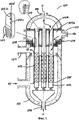
Предпочтительно, охлаждающая среда контактирует с углеводородным сырьем за пределами катализаторных труб. Охлаждающая среда проникает через трубчатую структуру, например через одно или несколько отверстий в ней, и проходит через зону устройства теплообменного риформинга вне катализаторных труб, где охлаждающая среда может быть смешана с поступающим углеводородным сырьем (подаваемым газом), таким образом, образуя углеводородно-паровую смесь, которая впоследствии вступает в контакт с катализатором, расположенным в катализаторных трубах. См. также Фиг.2. Более предпочтительно, охлаждающая среда вступает в контакт с углеводородным сырьем внутри катализаторных труб, а наиболее предпочтительно - до контакта с катализатором в трубах. Охлаждающая среда проходит внутрь катализаторных труб через одно или несколько отверстий, выполненных в верхней части катализаторных труб на уровне, по сути соответствующем уровню расположения трубчатой структуры и который, как правило, выше уровня заполнения катализатором катализаторных труб. См. Фиг.1. В любом из указанных выше вариантов, т.е. вне катализаторных труб или внутри катализаторных труб, охлаждающая среда пребывает в теплопроводящем отношении с трубчатой структурой и в связи по текучей среде с катализатором в катализаторных трубах.Preferably, the cooling medium is in contact with the hydrocarbon feed outside the catalyst tubes. The cooling medium penetrates through the tubular structure, for example, through one or more openings in it, and passes through the zone of the heat exchange reforming device outside the catalyst pipes, where the cooling medium can be mixed with the incoming hydrocarbon feed (feed gas), thereby forming a hydrocarbon-vapor mixture which subsequently comes into contact with the catalyst located in the catalyst pipes. See also FIG. 2. More preferably, the cooling medium comes into contact with the hydrocarbon feed within the catalyst tubes, and most preferably, before contact with the catalyst in the tubes. The cooling medium passes inside the catalyst pipes through one or more openings made in the upper part of the catalyst pipes at a level essentially corresponding to the level of the arrangement of the tubular structure and which, as a rule, is higher than the filling level of the catalyst pipes. See FIG. 1. In any of the above options, i.e. outside the catalyst pipes or inside the catalyst pipes, the cooling medium is thermally conductive with the tubular structure and in fluid communication with the catalyst in the catalyst pipes.
В еще одном варианте осуществления изобретения, в связи с одним или несколькими из указанных выше или ниже вариантов осуществления, способ дополнительно включает прохождение синтез-газа из устройства теплообменного риформинга через стадию автотермического риформинга (ATR) (или этап вторичного риформинга) с неподвижным слоем катализатора или стадию частичного окисления (РОх), необязательно с неподвижным слоем катализатора, вывод горячего отходящего потока синтез-газа, по меньшей мере часть которого используется в качестве теплоносителя в устройстве теплообменного риформинга, и вывод из устройства теплообменного риформинга конечного потока охлажденного синтез-газа. Таким образом, появляется возможность дополнительного риформинга синтез-газа из устройства теплообменного риформинга и использования газа, дополнительно подвергнутого риформингу, в качестве теплоносителя в устройстве теплообменного риформинга. Таким образом, охлажденный дополнительно подвергнутый риформингу газ впоследствии используют в качестве синтез-газа для производства аммиака, метанола, диметилового эфира (DME), углеводородов путем синтеза Фишера-Тропша или водорода, как определено в зависимом п.12.In yet another embodiment of the invention, in connection with one or more of the above or below embodiments, the method further comprises passing synthesis gas from the heat exchange reforming apparatus through an autothermal reforming (ATR) step (or secondary reforming step) with a fixed catalyst bed or partial oxidation stage (POx), optionally with a fixed catalyst bed, withdrawal of a hot synthesis gas effluent, at least a portion of which is used as a heat transfer medium in the heat exchange reforming device, and the output from the heat exchange reforming device of the final stream of cooled synthesis gas. Thus, it becomes possible to additionally reform the synthesis gas from the heat exchange reforming device and use the gas additionally subjected to reforming as a heat transfer medium in the heat exchange reforming device. Thus, the cooled additionally reformed gas is subsequently used as synthesis gas for the production of ammonia, methanol, dimethyl ether (DME), hydrocarbons by Fischer-Tropsch synthesis or hydrogen, as defined in
Для специалиста в данной области техники будет очевидно, что при производстве аммиака стадия автотермического риформинга (ATR) по существу представляет собой этап вторичного риформинга.It will be apparent to those skilled in the art that in the production of ammonia, the autothermal reforming (ATR) step is essentially a secondary reforming step.
В некоторых случаях этап частичного окисления (РОх) осуществляют без применения катализатора, однако, предпочтительно, частичное окисления (РОх) осуществляется с использованием неподвижного слоя катализатора.In some cases, the partial oxidation step (POx) is carried out without using a catalyst, however, preferably, the partial oxidation (POx) is carried out using a fixed catalyst bed.
Изобретение также включает используемое для осуществления данного способа устройство теплообменного риформинга. Таким образом, как указано в п.1, предложен аппарат (100) для производства синтез-газа из углеводородного сырья, включающий внешнюю оболочку (101); множество вертикально расположенных катализаторных труб (102), содержащих катализатор риформинга (103), заполняющий часть катализаторных труб (102); несущую конструкцию катализаторных труб (104), расположенную выше уровня заполнения катализатором (103) труб (102); средства (105) для непрямого нагрева катализаторных труб (102) теплообменной средой (10); входной канал (106) для подачи указанной теплообменной среды (10); выходной канал (107) для вывода указанной теплообменной среды после передачи средой тепла катализатору (103) внутри катализаторных труб (102); входной канал (108) для подачи углеводородного сырья (11), которое находится во взаимодействии в текучей форме с катализатором (103) внутри катализаторных труб (102); выходной канал (109) для вывода синтез-газа (12) после прохождения через катализаторные трубы (102); входной канал (110) для подачи охлаждающей среды (13), в котором эта охлаждающая среда (13) пребывает в теплопроводящей взаимосвязи, предпочтительно, прямой теплопроводящей взаимосвязи, со структурой катализаторных труб (104) и во взаимодействии в текучей форме с катализатором (103) внутри катализаторных труб (102).The invention also includes a heat exchange reforming device used to implement this method. Thus, as indicated in paragraph 1, the proposed apparatus (100) for the production of synthesis gas from hydrocarbons, including the outer shell (101); a plurality of vertically arranged catalyst pipes (102) containing a reforming catalyst (103) filling a portion of the catalyst pipes (102); the supporting structure of the catalyst pipes (104) located above the filling level of the pipes (102) with the catalyst (103); means (105) for indirectly heating the catalyst tubes (102) by a heat exchange medium (10); an inlet channel (106) for supplying said heat exchange medium (10); an output channel (107) for outputting said heat exchange medium after the medium transfers heat to the catalyst (103) inside the catalyst pipes (102); an inlet channel (108) for supplying hydrocarbon feed (11), which is in fluid interaction with the catalyst (103) inside the catalyst pipes (102); an output channel (109) for outputting the synthesis gas (12) after passing through the catalyst pipes (102); an inlet channel (110) for supplying a cooling medium (13) in which this cooling medium (13) is in a heat-conducting relationship, preferably a direct heat-conducting relationship, with the structure of the catalyst tubes (104) and in fluid interaction with the catalyst (103) inside the catalyst pipes (102).
Термин “во взаимодействии в текучей форме с катализатором” означает, что текучая среда, такая как углеводородное сырье, непосредственно контактирует с катализатором. Таким образом, следует понимать, что поскольку охлаждающая среда также находится во взаимодействии в текучей форме с катализатором, охлаждающая среда и углеводородное сырье находятся во взаимодействии в текучей форме друг с другом.The term “in fluid interaction with a catalyst” means that a fluid, such as a hydrocarbon feed, is in direct contact with the catalyst. Thus, it should be understood that since the cooling medium is also in fluid interaction with the catalyst, the cooling medium and hydrocarbon feed are in fluid interaction with each other.
Термин “в теплопроводящей взаимосвязи” включает прямую и косвенную передачу тепла. Таким образом, термин "в прямой теплопроводящей взаимосвязи" включает теплопередачу, при которой охлаждающая среда находится в прямом контакте с трубчатой структурой, т.е. непосредственно контактирует с металлическими деталями трубчатой структуры, тем самым обеспечивая быстрое охлаждение и защиту этих металлических деталей. Как правило, устройства теплообменного риформинга, расположенные между устройством парового преобразования метана (SMR) и устройством автотермического риформинга ATR (или устройством вторичного риформинга), сильно нагреваются: углеводородное сырье, поступающее в устройства теплообменного риформинга, имеет температуру в диапазоне от 750 до 1030°С, т.е. температуру, при которой металлические детали испытывают негативное воздействие и начинают терять прочность. Возможно добавление охлаждающей среды, предпочтительно пара, имеющей значительно более низкую температуру, как правило, 380°С. Пар может поступать из устройства теплообменного риформинга, но, предпочтительно, его вводят в поток риформинга, проходящий через катализаторные трубы, что оказывает на них положительное влияние. Таким образом, несущая конструкция труб может быть изготовлена из недорогих материалов, например материалов, отличных от инконеля (Inconel), поскольку температура несущей конструкции труб может быть значительно снижена, например до 400-450°С. Когда охлаждающая среда передает свое тепло трубчатой структуре через поверхность между ними, теплопроводящая взаимосвязь называется косвенной.The term “thermally conductive interconnection” includes direct and indirect heat transfer. Thus, the term “in direct heat-conducting relationship” includes heat transfer in which the cooling medium is in direct contact with the tubular structure, i.e. directly in contact with the metal parts of the tubular structure, thereby providing rapid cooling and protection of these metal parts. As a rule, heat exchange reforming devices located between the methane steam conversion device (SMR) and the ATR autothermal reforming device (or secondary reforming device) are very hot: the hydrocarbon feed entering the heat exchange reforming devices has a temperature in the range from 750 to 1030 ° С , i.e. the temperature at which metal parts are adversely affected and begin to lose strength. It is possible to add a cooling medium, preferably steam, having a significantly lower temperature, typically 380 ° C. The steam may come from a heat exchange reforming device, but preferably it is introduced into the reforming stream passing through the catalyst tubes, which has a positive effect on them. Thus, the supporting structure of the pipes can be made of inexpensive materials, for example, materials other than Inconel, since the temperature of the supporting structure of the pipes can be significantly reduced, for example, to 400-450 ° C. When the cooling medium transfers its heat to the tubular structure through the surface between them, the heat-conducting relationship is called indirect.
В связи с одним или несколькими из указанных выше или ниже вариантов осуществления устройство теплообменного риформинга предпочтительно выбирают из байонетного трубчатого реактора, кожухотрубного теплообменника и реактора с двойными трубами, в котором катализатор расположен внутри двойных труб, снаружи двойных труб и как снаружи, так и внутри двойных труб.In connection with one or more of the above or below embodiments, the heat exchange reforming device is preferably selected from a bayonet tube reactor, shell-and-tube heat exchanger, and double pipe reactor, in which the catalyst is located inside the double pipes, outside the double pipes and both outside and inside double pipes.
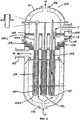
В конкретном варианте осуществления с использованием байонетного трубчатого реактора по меньшей мере одна из катализаторных труб (трубка риформинга) в этом устройстве риформинга представлена в форме внешней и внутренней трубы, где внешняя труба имеет U-образную форму и содержит катализатор риформинга, а внутренняя труба расположена концентрически и служит для вывода отходящего потока частично подвергнутого риформингу углеводорода из внешней трубы, внешняя труба концентрически окружена гильзой, расположенной на расстоянии от внешней трубы и предназначенной для передачи горячего отходящего потока от устройства автотермического риформинга (или вторичного риформинга) в косвенной теплопроводящей взаимосвязи с реагирующим сырьем в наружной трубе путем пропускания горячего отходящего потока в пространстве между гильзой и наружной трубой.In a specific embodiment, using a bayonet tube reactor, at least one of the catalyst tubes (reforming tube) in this reformer is in the form of an outer and inner tube, where the outer tube is U-shaped and contains a reforming catalyst and the inner tube is concentrically arranged and serves to output the effluent of the partially reformed hydrocarbon from the outer pipe, the outer pipe is concentrically surrounded by a sleeve located at a distance from the outer pipe and designed to transfer the hot effluent from the autothermal reforming device (or secondary reforming) in indirect heat-conducting relationship with the reacting raw materials in the outer pipe by passing the hot effluent in the space between the sleeve and the outer pipe.
В случае байонетного трубчатого реактора пар в камере смешивается за пределами катализаторных труб. Пар непосредственно контактирует с трубчатой структурой, охватывает часть всех катализаторных труб, проходящих через трубчатую структуру, проникает в трубчатую структуру, через, например, отверстие рядом с катализаторной трубой и смешивается с подаваемым газом. Комбинированный газ поступает в верхнюю часть катализаторных труб и продолжает перемещаться вниз, внутрь катализаторных труб. Под действием более высокого давления пара в камере пар поступает в катализаторные трубы и, таким образом, участвует в реакции риформинга.In the case of a bayonet tube reactor, steam in the chamber is mixed outside the catalyst tubes. The steam is in direct contact with the tubular structure, encompasses part of all the catalyst pipes passing through the tubular structure, penetrates the tubular structure, through, for example, an opening next to the catalyst pipe, and mixes with the feed gas. Combined gas enters the upper part of the catalyst pipes and continues to move downward, inside the catalyst pipes. Under the influence of a higher vapor pressure in the chamber, the vapor enters the catalyst pipes and, thus, participates in the reforming reaction.
В случае, если устройство теплообменного риформинга представляет собой кожухотрубный теплообменник, предпочтительно, чтобы подвергнутый частичному риформингу поток, выходящий из катализаторных труб в устройстве теплообменного риформинга, подавался в устройство автотермического риформинга (или вторичного риформинга), а горячий отходящий газ из устройства автотермического риформинга проходил через сторону кожуха устройства теплообменного риформинга для косвенного нагрева реакций риформинга, протекающих в катализаторных трубах.If the heat exchange reforming device is a shell-and-tube heat exchanger, it is preferable that the partially reformed stream exiting the catalyst pipes in the heat exchange reforming device is supplied to the autothermal reforming device (or secondary reforming) and the hot exhaust gas from the autothermal reforming device passes through the casing side of the heat exchange reforming device for indirectly heating the reforming reactions taking place in the catalyst pipes.
В случае, если устройство теплообменного риформинга представляет собой реактор с двойными трубами, в котором катализатор расположен внутри двойных труб, катализатор расположен снаружи двойных труб, и катализатор расположен как снаружи, так и внутри двойных труб, отходящий газ стадии автотермического риформинга проходит через кольцевую область двойных труб, а газ, подлежащий дальнейшему риформингу, пропускается через катализатор, расположенный внутри двойных труб и, необязательно, также и снаружи двойных труб. Двойная труба по существу представляет собой структуру из двух расположенных по существу концентрически труб. Пространство между стенками труб определяет кольцевую область, через которую протекает теплообменная среда, в этом случае поступающая из зоны автотермического риформинга (или вторичного риформинга).If the heat exchange reforming device is a double pipe reactor in which the catalyst is located inside the double pipes, the catalyst is located outside the double pipes, and the catalyst is located both outside and inside the double pipes, the exhaust gas of the autothermal reforming stage passes through the annular region of the double pipes, and the gas to be further reformed is passed through a catalyst located inside the double pipes and, optionally, also outside the double pipes. A double pipe is essentially a structure of two essentially concentrically arranged pipes. The space between the walls of the pipes defines the annular region through which the heat transfer medium flows, in this case coming from the zone of autothermal reforming (or secondary reforming).
В частности, в случае, когда устройство теплообменного риформинга представляет собой реактор с двойными трубами с катализатором, расположенным внутри двойных труб, такие катализаторные трубы могут иметь форму одной катализаторной трубы, окруженной гильзой или металлическим кожухом, расположенным на расстоянии от катализаторной трубы и создающим кольцевую область, через которую может проходить теплоноситель. Такая гильза или металлический кожух не обязательно должны быть частью катализаторной трубы как таковой, а служат для создания кольцевой области. В устройстве риформинга такого типа пар, вместо того чтобы охватывать все трубы, как в байонетном трубчатом реакторе, просто поступает в каждую катализаторную трубу через отверстия в трубе, например прорези, расположенные по длине верхней части катализаторных труб. Пар смешивается с углеводородным сырьем, подаваемым в верхнюю часть труб внутри катализаторных труб, чтобы участвовать в реакции риформинга, протекающей ниже по потоку, где комбинированный газ контактирует с катализатором. В более конкретном варианте осуществления изобретение, как определено в зависимом п.11, также включает устройство, в котором устройство теплообменного риформинга является реактором с двойными трубами с катализатором, расположенным внутри двойных труб, отличающееся тем, что охлаждающая среда 13 поступает в каждую катализаторную трубу 102 через отверстия 102b в трубах, расположенные по длине верхней части 102а катализаторных труб 102, и смешивается с углеводородным сырьем 11, поступающим в верхнюю часть катализаторных труб 102, при этом средства 102 с, такие как металлический кожух или гильза, простираются вдоль указанной верхней части 102а катализаторных труб 102 и создают пространство 102d по длине катализаторных труб 102 для прохождения охлаждающей среды 13. Охлаждающая среда непосредственно контактирует с трубчатой структурой 104, тем самым дополнительно охлаждая трубчатую структуру. Верхняя часть 102а катализаторных труб 102 определяется как часть катализаторных труб, которая проходит через трубчатую структуру 104 (см., например, Фиг.1).In particular, in the case where the heat exchange reforming apparatus is a double pipe reactor with a catalyst located inside the double pipes, such catalyst pipes may be in the form of a single catalyst pipe surrounded by a sleeve or metal casing located at a distance from the catalyst pipe and creating an annular region through which the heat carrier can pass. Such a sleeve or a metal casing does not have to be part of the catalyst pipe as such, but serve to create an annular region. In a reformer of this type of steam, instead of covering all the pipes, as in a bayonet-type tube reactor, it simply enters each catalyst pipe through openings in the pipe, for example, slots located along the length of the upper part of the catalyst pipes. Steam is mixed with hydrocarbon feed to the top of the tubes inside the catalyst tubes to participate in a reforming reaction that proceeds downstream where the combined gas is in contact with the catalyst. In a more specific embodiment, the invention, as defined in dependent claim 11, also includes a device in which the heat exchange reforming device is a double pipe reactor with a catalyst located inside the double pipes, characterized in that the cooling
В конкретном варианте осуществления изобретения, при газификации биомассы, в газификаторе, производящем синтез-газ, содержащий СО, СO2, Н2, Н2O, СН4, высшие углеводороды, аммиак и смолы при температуре около 850°С, применяется обработка путем 1- или 2-этапного риформинга смолы. Разложение смолы может происходить при температуре около 750°С, при которой происходит распад тяжелых смол. Однако, если синтез-газ будет использоваться для производства жидкостей, таких как дизельное топливо FT, бензин TIGAS, DME, МеОН и т.д., очень важно уменьшить показатель остаточного метана, т.е. содержание метана в синтез-газе, чтобы ограничить очистку в контуре синтеза. Это можно осуществить в устройстве риформинга с подогревом. Однако стандартные реакторы риформинга не могут работать с температурами на входе около 750°С. Для этой цели было бы выгодным использовать охлаждаемое паром устройство теплообменного риформинга в соответствии с настоящим изобретением. В этом варианте осуществления реактор может нагреваться, например, топочным газом, получаемым в результате сжигания остаточных газов синтеза.In a specific embodiment of the invention, when gasifying biomass, in a gasifier producing synthesis gas containing CO, CO 2 , H 2 , H 2 O, CH 4 , higher hydrocarbons, ammonia and resins at a temperature of about 850 ° C, processing by 1- or 2-stage resin reforming. Resin decomposition can occur at a temperature of about 750 ° C, at which the decomposition of heavy resins occurs. However, if the synthesis gas will be used to produce liquids such as FT diesel fuel, TIGAS gasoline, DME, MeOH, etc., it is very important to reduce the residual methane index, i.e. the methane content in the synthesis gas to limit purification in the synthesis loop. This can be done in a heated reformer. However, standard reforming reactors cannot operate at inlet temperatures of about 750 ° C. For this purpose, it would be advantageous to use a steam-cooled heat exchange reforming apparatus in accordance with the present invention. In this embodiment, the reactor may be heated, for example, by flue gas resulting from the combustion of residual synthesis gases.
Признаки изобретения.The features of the invention.
1. Способ получения синтез-газа из углеводородного сырья, включающий пропускание углеводородного сырья через этап риформинга в устройстве теплообменного риформинга, содержащем множество катализаторных труб, содержащих катализатор риформинга в непрямой теплопроводящей взаимосвязи с теплоносителем, и вывод из устройства теплообменного риформинга синтез-газа в виде потока подвергнутых риформингу углеводородов, отличающийся тем, что этот способ дополнительно включает добавление охлаждающей среды в устройство теплообменного риформинга.1. A method of producing synthesis gas from a hydrocarbon feedstock, comprising passing the hydrocarbon feedstock through a reforming step in a heat exchange reforming apparatus comprising a plurality of catalyst tubes containing a reforming catalyst in indirect heat transfer relationship with a heat transfer agent, and withdrawing synthesis gas from the heat transfer reforming reformer in the form of a stream subjected to hydrocarbon reforming, characterized in that the method further comprises adding a cooling medium to the heat exchange reformin a.
2. Способ по п.1, включающий добавление охлаждающей среды непосредственно в несущую конструкцию труб устройства теплообменного риформинга.2. The method according to claim 1, comprising adding a cooling medium directly to the supporting structure of the pipes of the heat exchange reforming device.
3. Способ по п.1 или 2, отличающийся тем, что способ дополнительно включает смешивание охлаждающей среды в устройстве теплообменного риформинга с углеводородным сырьем, поступающим в устройство теплообменного риформинга.3. The method according to
4. Способ по любому из пп.1-3, отличающийся тем, что охлаждающей средой является пар.4. The method according to any one of claims 1 to 3, characterized in that the cooling medium is steam.
5. Способ по п.3 или 4, отличающийся тем, что охлаждающая среда контактирует с углеводородным сырьем за пределами катализаторных труб.5. The method according to
6. Способ по п.3 или 4, отличающийся тем, что охлаждающая среда контактирует с углеводородной смесью внутри катализаторных труб.6. The method according to
7. Способ по любому из пп.1-6, дополнительно включающий прохождение синтез-газа из устройства теплообменного риформинга через стадию автотермического риформинга (ATR) с неподвижным слоем катализатора или стадию частичного окисления (РОх), вывод горячего отходящего потока синтез-газа, по меньшей мере часть которого используется в качестве теплоносителя в устройстве теплообменного риформинга, и вывод из устройства теплообменного риформинга конечного потока охлажденного синтез-газа.7. The method according to any one of claims 1 to 6, further comprising passing the synthesis gas from the heat exchange reforming device through the stage of autothermal reforming (ATR) with a fixed catalyst bed or the stage of partial oxidation (POx), the output of the hot exhaust stream of synthesis gas, at least a portion of which is used as a heat carrier in the heat exchange reforming device, and the output from the heat exchange reforming device of the final stream of cooled synthesis gas.
8. Способ по п.7, дополнительно включающий преобразование выходящего синтез-газа стадии (b) в синтез-газ для производства аммиака, синтез-газ для производства метанола, синтез-газ для производства DME, синтез-газ для производства углеводородов путем синтеза Фишера-Тропша или водород.8. The method according to claim 7, further comprising converting the outgoing synthesis gas of step (b) into synthesis gas for the production of ammonia, synthesis gas for the production of methanol, synthesis gas for the production of DME, synthesis gas for the production of hydrocarbons by Fischer synthesis -Tropsha or hydrogen.
9. Аппарат (100) для осуществления способа по любому из пп.1-8, включающий внешнюю оболочку (101); множество вертикально расположенных катализаторных труб (102), содержащих катализатор риформинга (103), заполняющий часть катализаторных труб (102); несущую конструкцию катализаторных труб (104); средства (105) для непрямого нагрева катализаторных труб (102) теплообменной средой (10); входной канал (106) для подачи указанной теплообменной среды (10); выходной канал (107) для вывода указанной теплообменной среды после передачи средой тепла катализатору (103); входной канал (108) для подачи углеводородного сырья (11), которое находится во взаимодействии в текучей форме с катализатором (103) внутри катализаторных труб (102); выходной канал (109) для вывода синтез-газа (12) после прохождения через катализаторные трубы (102); входной канал (110) для подачи охлаждающей среды (13), в котором эта охлаждающая среда (13) пребывает в теплопроводящей взаимосвязи со структурой катализаторных труб (104) и во взаимодействии в текучей форме с катализатором (103) внутри катализаторных труб (102).9. The apparatus (100) for implementing the method according to any one of claims 1 to 8, including the outer shell (101); a plurality of vertically arranged catalyst pipes (102) containing a reforming catalyst (103) filling a portion of the catalyst pipes (102); supporting structure of catalyst pipes (104); means (105) for indirectly heating the catalyst tubes (102) by a heat exchange medium (10); an inlet channel (106) for supplying said heat exchange medium (10); an output channel (107) for outputting said heat exchange medium after the medium transfers heat to the catalyst (103); an inlet channel (108) for supplying hydrocarbon feed (11), which is in fluid interaction with the catalyst (103) inside the catalyst pipes (102); an output channel (109) for outputting the synthesis gas (12) after passing through the catalyst pipes (102); an inlet channel (110) for supplying a cooling medium (13), in which this cooling medium (13) is in heat-conducting relationship with the structure of the catalyst pipes (104) and in fluid interaction with the catalyst (103) inside the catalyst pipes (102).
10. Аппарат по п.9 в виде устройства теплообменного риформинга, выбираемого из:10. The apparatus according to claim 9 in the form of a heat exchange reforming device selected from:
- байонетного трубчатого реактора;- bayonet tubular reactor;
- кожухотрубного теплообменника;- shell and tube heat exchanger;
- реактора с двойными трубами с катализатором, расположенным внутри двойных труб;- a double pipe reactor with a catalyst located inside the double pipes;
- реактора с двойными трубами с катализатором, расположенным снаружи двойных труб;- a double pipe reactor with a catalyst located outside the double pipes;
- реактора с двойными трубами с катализатором, расположенным как внутри, так и снаружи двойных труб.- a double pipe reactor with a catalyst located both inside and outside the double pipes.
11. Аппарат (100) по п.9 или 10, в котором устройство теплообменного риформинга является реактором с двойными трубами с катализатором, расположенным внутри двойных труб, отличающийся тем, что охлаждающая среда (13) поступает в каждую катализаторную трубу (102) через отверстия (102b) в трубах, расположенные по длине верхней части (102а) катализаторных труб (102), и смешивается с углеводородным сырьем (11), поступающим в верхнюю часть катализаторных труб (102), и тем, что средства (102с) простираются вдоль указанной верхней части (102а) катализаторных труб (102) и создают пространство (102d) по длине катализаторных труб (102) для прохождения охлаждающей среды (13).11. The apparatus (100) according to
12. Аппарат (100) по п.9 или 10, в котором устройство теплообменного риформинга является кожухотрубным теплообменником с перегородками, с катализатором, расположенным внутри труб, отличающийся тем, что охлаждающая среда (13) поступает в каждую катализаторную трубу (102) через отверстия (102b) в трубах, расположенные по длине верхней части (102а) катализаторных труб (102), и смешивается с углеводородным сырьем (11), поступающим в верхнюю часть катализаторных труб (102), и тем, что средства (102 с) простираются вдоль указанной верхней части (102а) катализаторных труб (102) и создают пространство (102d) по длине катализаторных труб (102) для прохождения охлаждающей среды (13).12. The apparatus (100) according to
На прилагаемых чертежах изображены конкретные варианты реализации аппарата по настоящему изобретению в виде устройства теплообменного риформинга двухтрубного типа с катализатором внутри труб (Фиг.1) и устройства теплообменного риформинга байонетно-трубного типа (Фиг.2).The accompanying drawings show specific embodiments of the apparatus of the present invention in the form of a two-pipe type heat exchange reforming device with a catalyst inside the pipes (FIG. 1) and a bayonet-tube type heat exchange reforming device (FIG. 2).
На фиг.1 устройство теплообменного риформинга 100 включает внешнюю оболочку 101; множество вертикально расположенных катализаторных труб 102, содержащих катализатор риформинга 103, который заполняет часть катализаторных труб 102, несущую конструкцию катализаторных труб 104, расположенную выше уровня заполнения катализатором 103 труб 102. Несущая конструкция труб 104 определяет верхнюю камеру 104а, через которую проходит верхняя часть 102а катализаторных труб 102. Устройство риформинга 100 содержит также средства 105 для непрямого нагрева катализаторных труб 102 теплообменной средой 10. Средства 105 могут иметь форму гильзы или металлического кожуха, простирающегося по длине катализаторных труб 102 примерно до уровня заполнения катализатором 103 труб 102, тем самым образуя кольцевую область для прохождения теплоносителя 10. Устройство риформинга 100 также содержит входной канал 106 для подачи указанной теплообменной среды 10, подаваемой, как правило, при 1030°С как отходящий газ из зоны автотермического риформинга (или вторичного риформинга); выходной канал 107 для вывода указанной теплообменной среды 10, как правило, при 825°С после передачи тепла катализатору 103, расположенному внутри катализаторных труб 102, и после прохождения через кольцевую область, образованную между средствами 105 и катализаторными трубами 102. Этот охлажденный синтез-газ 10 подается в расположенное ниже по потоку оборудование, например котлы-утилизаторы, и далее используется в последующих стадиях, таких как синтез метанола, синтез DME, синтез аммиака и синтез Фишера-Тропша. Устройство риформинга 100 также содержит входной канал 108 для подачи углеводородного сырья 11, поступающего, как правило, при температуре 750°С в случае вывода из расположенного впереди устройства парового преобразования метана (SMR) и находящегося во взаимодействии в текучей форме с катализатором 103, расположенным внутри катализаторных труб 102. Выходной канал 109 предназначен для вывода синтез-газа 12, как правило, при 810°С после прохождения через катализаторные трубы 102. Синтез-газ может подвергаться дальнейшему риформингу ниже по потоку в устройстве автотермического риформинга (или вторичного риформинга). Имеется входной канал 110 для подачи охлаждающей среды 13. Этой охлаждающей средой 13 обычно является охлаждающий газ, такой как пар при температуре около 380°С, находящийся в теплопроводящей взаимосвязи со структурой катализаторных труб 104 и во взаимодействии в текучей форме с катализатором 103, расположенным внутри катализаторных труб 102. Пар 13 проходит через отверстия 102b, выполненные по длине верхней части 102а катализаторных труб 102. Металлический кожух или гильза 102с проходит вдоль верхней части 102а катализаторных труб и, таким образом, вдоль участка, где расположены отверстия 102с. Наличие металлического кожуха или гильзы 102с создает пространство 102d по длине верхней части 102а катализаторной трубы 102 и, соответственно, по длине катализаторной трубы 102, непосредственно контактирующей с трубчатой структурой 104. Пространство 102d обеспечивает возможность прохождения охлаждающей среды - пара 13, тем самым дополнительно охлаждая трубчатую структуру 104.1, a heat
На фиг.2 изображено устройство теплообменного риформинга 100 байонетно-трубчатого типа, включающее внешнюю оболочку 101; множество вертикально расположенных катализаторных труб 102, содержащих катализатор риформинга 103, который заполняет часть катализаторных труб 102. Катализаторные трубы 102 имеют форму двойных труб с внешней и внутренней трубами, где внешняя труба 102b является U-образной трубой и содержит катализатор 103, внутренняя труба 102 с расположена по центру, не содержит катализатора и предназначена для вывода отходящего потока частично подвергнутого риформингу углеводорода из внешней трубы 102b, как обозначено стрелками. Несущая конструкция катализаторных труб 104 расположена выше уровня заполнения катализатором 103 труб 102. Несущая конструкция труб 104 определяет верхнюю камеру 104а, через которую проходит верхняя часть катализаторных труб 102а. Устройство риформинга 100 содержит также средства 105 для непрямого нагрева катализаторных труб 102 теплообменной средой 10. Средства 105 имеют форму гильзы или металлического кожуха, концентрически окружающего внешнюю трубу 102b и простирающегося по длине катализаторных труб 102 примерно до уровня заполнения катализатором 103 труб 102. Гильза или металлический кожух 105, таким образом, образует кольцевую область для прохождения теплоносителя 10. Устройство риформинга 100 также содержит входной канал 106 для подачи указанной теплообменной среды 10, поступающей, как правило, при 1030°С как отходящий газ из зоны вторичного или автотермического риформинга (или автотермического риформинга), который проходит через указанную кольцевую область, определенную пространством между средствами 105 и внешней трубой 102b. Выходной канал 107 предназначен для вывода указанной теплообменной среды 10, как правило, при 825°С после передачи тепла катализатору 103, расположенному внутри катализаторных труб 102, и после прохождения через кольцевую область, образованную между средствами 105 и катализаторными трубами 102. Этот охлажденный синтез-газ 10 подается в расположенное ниже по потоку оборудование, например котлы-утилизаторы, и далее используется в последующих стадиях, таких как синтез метанола, синтез DME, синтез аммиака и синтез Фишера-Тропша. Устройство риформинга 100 также содержит входной канал 108 для подачи углеводородного сырья 11, поступающего, как правило, при температуре 750°С в случае вывода из расположенного впереди устройства парового преобразования метана (SMR) и находящегося во взаимодействии в текучей форме с катализатором 103, расположенным внутри катализаторных труб 102. Выходной канал 109, расположенный в верхней части устройства риформинга 100, предназначен для вывода синтез-газа 12, как правило, при 810°С после прохождения через катализаторные трубы 102. Синтез-газ 12 может подвергаться дальнейшему риформингу ниже по потоку в устройстве вторичного риформинга (или автотермического риформинга). Имеется входной канал 110 для подачи охлаждающей среды 13. Этой охлаждающей средой 13 обычно является пар при температуре около 380°С, находящийся в теплопроводящей взаимосвязи со структурой катализаторных труб 104 и во взаимодействии в текучей форме с катализатором 103, расположенным внутри катализаторных труб 102. В этом устройстве риформинга байонетно-трубчатого типа пар 13 смешивается вне катализаторных труб 102, как показано стрелками. Пар непосредственно контактирует с трубчатой структурой, охватывает часть 102а всех катализаторных труб, проходящих через трубчатую структуру, и проникает в трубчатую структуру перед смешиванием с поступающим газом 11. Комбинированный газ поступает в верхнюю часть катализаторных труб и продолжает перемещаться вниз, внутрь катализаторных труб. Под действием более высокого давления пара в камере пар поступает в катализаторные трубы и, таким образом, участвует в реакции риформинга.Figure 2 shows a device for heat exchange reforming 100 bayonet-tube type, including an
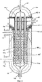
На фиг.3 изображено устройство теплообменного риформинга 100 в варианте, в котором перегородки обеспечивают более эффективный теплообмен между теплообменной средой 10 и катализаторными трубами 102. Как видно на фиг.1, перегородки заставляют теплообменную среду 10 протекать зигзагообразно и проходить через катализаторные трубы 102, по существу, перпендикулярно продольной оси катализаторных труб 102. Конструкция перегородок обеспечивает эффективный теплообмен, и, неожиданно, расчеты показывают, что конфигурация с перегородками может обеспечить до 50% снижение стоимости реактора.FIG. 3 shows a heat
Claims (9)
- байонетного трубчатого реактора;
- кожухотрубного теплообменника;
- реактора с двойными трубами с катализатором, расположенным внутри двойных труб;
- реактора с двойными трубами с катализатором, расположенным как внутри, так и снаружи двойных труб.2. The apparatus according to claim 1, which is a heat exchange reforming device, selected from:
- bayonet tubular reactor;
- shell and tube heat exchanger;
- a double pipe reactor with a catalyst located inside the double pipes;
- a double pipe reactor with a catalyst located both inside and outside the double pipes.
Applications Claiming Priority (5)
| Application Number | Priority Date | Filing Date | Title |
|---|---|---|---|
| DKPA201000038 | 2010-01-19 | ||
| DKPA201000038 | 2010-01-19 | ||
| DKPA201000377 | 2010-04-27 | ||
| DKPA20100377 | 2010-04-27 | ||
| PCT/EP2011/000179 WO2011088982A1 (en) | 2010-01-19 | 2011-01-18 | Process and apparatus for reforming hydrocarbons |
Publications (2)
| Publication Number | Publication Date |
|---|---|
| RU2012135374A RU2012135374A (en) | 2014-02-27 |
| RU2552460C2 true RU2552460C2 (en) | 2015-06-10 |
Family
ID=43858372
Family Applications (1)
| Application Number | Title | Priority Date | Filing Date |
|---|---|---|---|
| RU2012135374/05A RU2552460C2 (en) | 2010-01-19 | 2011-01-18 | Method and process vessel for hydrocarbons reforming |
Country Status (9)
| Country | Link |
|---|---|
| US (1) | US9227844B2 (en) |
| EP (1) | EP2526045B1 (en) |
| JP (1) | JP5757581B2 (en) |
| KR (1) | KR101826064B1 (en) |
| CN (1) | CN102811944B (en) |
| CA (1) | CA2786448C (en) |
| PL (1) | PL2526045T3 (en) |
| RU (1) | RU2552460C2 (en) |
| WO (1) | WO2011088982A1 (en) |
Families Citing this family (23)
| Publication number | Priority date | Publication date | Assignee | Title |
|---|---|---|---|---|
| CN103111239B (en) * | 2011-11-16 | 2015-09-30 | 西安核设备有限公司 | A kind of air cooling methanol reactor |
| US20140241949A1 (en) * | 2012-03-26 | 2014-08-28 | Sundrop Fuels, Inc. | Radiant heat tube chemical reactor |
| WO2013149112A1 (en) | 2012-03-30 | 2013-10-03 | Monsanto Technology Llc | Alcohol reforming system for internal combustion engine |
| WO2013149118A1 (en) * | 2012-03-30 | 2013-10-03 | Monsanto Technology Llc | Alcohol reformer for reforming alcohol to mixture of gas including hydrogen |
| US9358526B2 (en) | 2013-11-19 | 2016-06-07 | Emerging Fuels Technology, Inc. | Optimized fischer-tropsch catalyst |
| US9180436B1 (en) | 2013-11-19 | 2015-11-10 | Emerging Fuels Technology, Inc. | Optimized fischer-tropsch catalyst |
| RU2554008C1 (en) * | 2014-01-13 | 2015-06-20 | Общество с ограниченной ответственностью "Газохим Техно" | Reactor for partial oxidation of hydrocarbon gases |
| US10525428B2 (en) * | 2015-03-20 | 2020-01-07 | Haldor Topsoe A/S | Boiling water reactor |
| CN105347301B (en) * | 2015-12-10 | 2018-01-05 | 刘建安 | A kind of combustible gas generating device |
| ES2928946T3 (en) * | 2015-12-30 | 2022-11-23 | Forestgas Oy | Arrangement and method for preparing a gas |
| WO2017138028A1 (en) * | 2016-02-08 | 2017-08-17 | Kt Kinetics Technology Spa | Enhanced efficiency endothermic reactor for syngas production with flexible heat recovery to meet low export steam generation. |
| KR102447384B1 (en) | 2016-10-25 | 2022-09-28 | 테크니프 에너지스 프랑스 | catalyst tube for reforming |
| US11506122B2 (en) | 2016-11-09 | 2022-11-22 | 8 Rivers Capital, Llc | Systems and methods for power production with integrated production of hydrogen |
| KR102079036B1 (en) * | 2016-12-28 | 2020-02-20 | 한국화학연구원 | Highly efficient conversion method of methane via combined exothermic and endothermic reaction |
| CN106987284B (en) * | 2017-04-17 | 2019-08-02 | 东南大学 | The device and method for transformation of tar removing conversion in a kind of biomass synthesis gas |
| ES2842423T3 (en) | 2017-05-26 | 2021-07-14 | Alfa Laval Olmi S P A | Shell and Tube Heat Exchanger |
| EP3406970A1 (en) | 2017-05-26 | 2018-11-28 | ALFA LAVAL OLMI S.p.A. | Vapour and liquid drum for a shell-and-tube heat exchanger |
| AU2020292848A1 (en) | 2019-06-13 | 2022-02-03 | 8 Rivers Capital, Llc | Power production with cogeneration of further products |
| EP3990164A1 (en) | 2019-06-28 | 2022-05-04 | Technip Energies France | Method of loading a tubular reactor with a catalyst tube assembly, and a catalyst tube assembly for a tubular reactor |
| BR112022003964A2 (en) * | 2019-09-03 | 2022-05-24 | Haldor Topsoe As | Reform furnace with supported reformer tubes |
| KR102602141B1 (en) * | 2021-10-06 | 2023-11-14 | 두산에너빌리티 주식회사 | Combined reformer |
| WO2023084084A1 (en) | 2021-11-15 | 2023-05-19 | Topsoe A/S | Blue hydrogen process and plant |
| WO2023089571A1 (en) * | 2021-11-18 | 2023-05-25 | 8 Rivers Capital, Llc | Method for hydrogen production |
Citations (1)
| Publication number | Priority date | Publication date | Assignee | Title |
|---|---|---|---|---|
| RU2053957C1 (en) * | 1990-02-02 | 1996-02-10 | Хальдор Топсее А/С | Method and aggregate for hydrocarbons conversion by steam reformer |
Family Cites Families (25)
| Publication number | Priority date | Publication date | Assignee | Title |
|---|---|---|---|---|
| US3334971A (en) | 1964-08-18 | 1967-08-08 | Chemical Construction Corp | Catalytically reforming hydrocarbon and steam mixtures |
| US3515520A (en) * | 1967-02-13 | 1970-06-02 | Universal Oil Prod Co | Reactor with internal protective sleeve for corrosive systems |
| JPS5382690A (en) * | 1976-12-29 | 1978-07-21 | Chiyoda Chem Eng & Constr Co Ltd | Improved preparation of synthetic gas for ammonia |
| US4337170A (en) | 1980-01-23 | 1982-06-29 | Union Carbide Corporation | Catalytic steam reforming of hydrocarbons |
| IT1141031B (en) | 1980-08-29 | 1986-10-01 | Snam Progetti | PROCEDURE FOR THE PREPARATION OF GASES CONTAINING HYDROGEN AND NITROGEN |
| JPS59217605A (en) | 1983-05-26 | 1984-12-07 | Babcock Hitachi Kk | Apparatus for generating hydrogen |
| DE3430792C1 (en) * | 1984-08-22 | 1986-04-30 | Ed. Züblin AG, 7000 Stuttgart | Process for lowering membrane sections into suspension-supported vertical slots and device for carrying out the process |
| EP0194067B2 (en) | 1985-03-05 | 1994-05-11 | Imperial Chemical Industries Plc | Steam reforming hydrocarbons |
| DE3540782A1 (en) * | 1985-11-16 | 1987-05-21 | Uhde Gmbh | Apparatus for endothermal catalytic cracking of hydrocarbons |
| DE68909979D1 (en) | 1988-03-24 | 1993-11-25 | Ici Plc | Two-stage steam reforming process. |
| US5106590A (en) * | 1990-05-11 | 1992-04-21 | Davy Mckee (London) Limited | Gas mixer and distributor with heat exchange between incoming gases |
| DK162891A (en) * | 1991-09-23 | 1993-03-24 | Haldor Topsoe As | PROCEDURE AND REACTOR FOR IMPLEMENTING NON-ADIABATIC REACTIONS. |
| US5429809A (en) * | 1991-09-23 | 1995-07-04 | Haldor Topsoe A/S | Process and reactor for carrying out non-adiabatic catalytic reactions |
| DE59503581D1 (en) * | 1994-06-15 | 1998-10-22 | Dbb Fuel Cell Engines Gmbh | Two-stage methanol reforming |
| US6296814B1 (en) * | 1998-11-10 | 2001-10-02 | International Fuel Cells, L.L.C. | Hydrocarbon fuel gas reformer assembly for a fuel cell power plant |
| US6497856B1 (en) * | 2000-08-21 | 2002-12-24 | H2Gen Innovations, Inc. | System for hydrogen generation through steam reforming of hydrocarbons and integrated chemical reactor for hydrogen production from hydrocarbons |
| DE10142999B4 (en) * | 2001-09-03 | 2006-07-06 | Zentrum für Brennstoffzellen Technik ZBT Duisburg GmbH | Highly efficient, compact reformer unit for hydrogen production from gaseous hydrocarbons in the small power range |
| CA2415536A1 (en) * | 2002-12-31 | 2004-06-30 | Long Manufacturing Ltd. | Reformer for converting fuel to hydrogen |
| CN1774393A (en) * | 2003-04-15 | 2006-05-17 | 国际壳牌研究有限公司 | Reactor for performing a steam reforming reaction and a process to prepare synthesis gas |
| JP4048277B2 (en) | 2003-08-06 | 2008-02-20 | 国立大学法人東北大学 | Biomass gasification method and gasification apparatus |
| JP4477432B2 (en) | 2004-06-29 | 2010-06-09 | 東洋エンジニアリング株式会社 | Reformer |
| JP2007229548A (en) * | 2006-02-27 | 2007-09-13 | Nippon Steel Engineering Co Ltd | Reforming catalyst acted in biomass pyrolysis gasification process, its manufacturing method and modification process using the reforming catalyst, biomass pyrolytic gasifying device, and method for regenerating catalyst |
| GR1006128B (en) * | 2007-05-25 | 2008-11-03 | . | Higly thermally integrated reformer for hydrogen production. |
| US8178062B2 (en) * | 2007-09-27 | 2012-05-15 | Sanyo Electric Co., Ltd. | Reforming apparatus for fuel cell |
| US20090184293A1 (en) * | 2008-01-18 | 2009-07-23 | Han Pat A | Process for reforming hydrocarbons |
-
2011
- 2011-01-18 CN CN201180006565.5A patent/CN102811944B/en active Active
- 2011-01-18 RU RU2012135374/05A patent/RU2552460C2/en active
- 2011-01-18 WO PCT/EP2011/000179 patent/WO2011088982A1/en active Application Filing
- 2011-01-18 CA CA2786448A patent/CA2786448C/en active Active
- 2011-01-18 KR KR1020127021397A patent/KR101826064B1/en active IP Right Grant
- 2011-01-18 PL PL11704919T patent/PL2526045T3/en unknown
- 2011-01-18 EP EP11704919.7A patent/EP2526045B1/en active Active
- 2011-01-18 JP JP2012549284A patent/JP5757581B2/en active Active
- 2011-01-18 US US13/522,341 patent/US9227844B2/en active Active
Patent Citations (1)
| Publication number | Priority date | Publication date | Assignee | Title |
|---|---|---|---|---|
| RU2053957C1 (en) * | 1990-02-02 | 1996-02-10 | Хальдор Топсее А/С | Method and aggregate for hydrocarbons conversion by steam reformer |
Also Published As
| Publication number | Publication date |
|---|---|
| CA2786448C (en) | 2018-09-25 |
| RU2012135374A (en) | 2014-02-27 |
| BR112012017774A2 (en) | 2017-10-03 |
| JP2013517213A (en) | 2013-05-16 |
| US9227844B2 (en) | 2016-01-05 |
| CN102811944B (en) | 2015-05-20 |
| CN102811944A (en) | 2012-12-05 |
| EP2526045A1 (en) | 2012-11-28 |
| WO2011088982A8 (en) | 2012-08-16 |
| CA2786448A1 (en) | 2011-07-28 |
| KR20120127453A (en) | 2012-11-21 |
| US20120277327A1 (en) | 2012-11-01 |
| PL2526045T3 (en) | 2018-10-31 |
| JP5757581B2 (en) | 2015-07-29 |
| WO2011088982A1 (en) | 2011-07-28 |
| EP2526045B1 (en) | 2018-03-07 |
| KR101826064B1 (en) | 2018-02-07 |
Similar Documents
| Publication | Publication Date | Title |
|---|---|---|
| RU2552460C2 (en) | Method and process vessel for hydrocarbons reforming | |
| US20200361768A1 (en) | Heat integrated reformer with catalytic combustion for hydrogen production | |
| RU2560363C2 (en) | Hydrocarbon reforming method | |
| US6887285B2 (en) | Dual stack compact fuel processor for producing hydrogen rich gas | |
| EP1899046B1 (en) | Compact reforming reactor | |
| US7670395B2 (en) | Compact reforming reactor | |
| CN100519707C (en) | Method and apparatus for rapid heating of fuel reforming reactants | |
| US11813584B2 (en) | Combined reforming apparatus | |
| US6899861B2 (en) | Heat exchanger mechanization to transfer reformate energy to steam and air | |
| CA2685284C (en) | Highly heat integrated fuel processor for hydrogen production | |
| KR20240017375A (en) | Heat exchange reactor with reduced metal dusting | |
| BR112012017774B1 (en) | APPLIANCE FOR CONDUCTING A PROCESS FOR THE PRODUCTION OF SYNTHESIS GAS, PROCESS FOR THE PRODUCTION OF SYNTHESIS GAS FROM A FEEDING LOAD OF HYDROCARBONS, AND, USE OF THE APPLIANCE | |
| KR20200010949A (en) | Module type reforming reactor | |
| CN116802452A (en) | Sealing device for heat exchange reactor | |
| Grotz | Apparatus for ammonia synthesis | |
| JP2007191367A (en) | Reactor for producing synthesis gas integrated with exhaust-heat recovery unit |