RU2552103C2 - Replaceable module for moving miner controllers - Google Patents
Replaceable module for moving miner controllers Download PDFInfo
- Publication number
- RU2552103C2 RU2552103C2 RU2012129891/07A RU2012129891A RU2552103C2 RU 2552103 C2 RU2552103 C2 RU 2552103C2 RU 2012129891/07 A RU2012129891/07 A RU 2012129891/07A RU 2012129891 A RU2012129891 A RU 2012129891A RU 2552103 C2 RU2552103 C2 RU 2552103C2
- Authority
- RU
- Russia
- Prior art keywords
- housing
- connector
- replaceable module
- module according
- panel
- Prior art date
Links
- 238000005065 mining Methods 0.000 claims abstract description 17
- 239000002184 metal Substances 0.000 claims description 15
- 238000005192 partition Methods 0.000 claims description 6
- 150000001875 compounds Chemical class 0.000 claims description 5
- 238000007789 sealing Methods 0.000 claims description 5
- 239000004020 conductor Substances 0.000 claims description 4
- 239000000126 substance Substances 0.000 abstract 1
- 238000009434 installation Methods 0.000 description 5
- 229910001220 stainless steel Inorganic materials 0.000 description 3
- 239000010935 stainless steel Substances 0.000 description 3
- 230000007613 environmental effect Effects 0.000 description 2
- 238000004880 explosion Methods 0.000 description 2
- 238000000034 method Methods 0.000 description 2
- 241001124569 Lycaenidae Species 0.000 description 1
- 238000005452 bending Methods 0.000 description 1
- 239000003245 coal Substances 0.000 description 1
- 239000000470 constituent Substances 0.000 description 1
- 238000001746 injection moulding Methods 0.000 description 1
- 229910052500 inorganic mineral Inorganic materials 0.000 description 1
- 239000003077 lignite Substances 0.000 description 1
- 239000000463 material Substances 0.000 description 1
- 238000005259 measurement Methods 0.000 description 1
- 239000011707 mineral Substances 0.000 description 1
- 230000002787 reinforcement Effects 0.000 description 1
- 150000003839 salts Chemical class 0.000 description 1
- 230000035939 shock Effects 0.000 description 1
- 230000011664 signaling Effects 0.000 description 1
Images
Classifications
-
- H—ELECTRICITY
- H05—ELECTRIC TECHNIQUES NOT OTHERWISE PROVIDED FOR
- H05K—PRINTED CIRCUITS; CASINGS OR CONSTRUCTIONAL DETAILS OF ELECTRIC APPARATUS; MANUFACTURE OF ASSEMBLAGES OF ELECTRICAL COMPONENTS
- H05K7/00—Constructional details common to different types of electric apparatus
- H05K7/14—Mounting supporting structure in casing or on frame or rack
- H05K7/1462—Mounting supporting structure in casing or on frame or rack for programmable logic controllers [PLC] for automation or industrial process control
- H05K7/1475—Bus assemblies for establishing communication between PLC modules
- H05K7/1477—Bus assemblies for establishing communication between PLC modules including backplanes
-
- H—ELECTRICITY
- H05—ELECTRIC TECHNIQUES NOT OTHERWISE PROVIDED FOR
- H05K—PRINTED CIRCUITS; CASINGS OR CONSTRUCTIONAL DETAILS OF ELECTRIC APPARATUS; MANUFACTURE OF ASSEMBLAGES OF ELECTRICAL COMPONENTS
- H05K7/00—Constructional details common to different types of electric apparatus
- H05K7/14—Mounting supporting structure in casing or on frame or rack
- H05K7/1462—Mounting supporting structure in casing or on frame or rack for programmable logic controllers [PLC] for automation or industrial process control
- H05K7/1468—Mechanical features of input/output (I/O) modules
-
- H—ELECTRICITY
- H05—ELECTRIC TECHNIQUES NOT OTHERWISE PROVIDED FOR
- H05K—PRINTED CIRCUITS; CASINGS OR CONSTRUCTIONAL DETAILS OF ELECTRIC APPARATUS; MANUFACTURE OF ASSEMBLAGES OF ELECTRICAL COMPONENTS
- H05K1/00—Printed circuits
- H05K1/02—Details
- H05K1/14—Structural association of two or more printed circuits
- H05K1/148—Arrangements of two or more hingeably connected rigid printed circuit boards, i.e. connected by flexible means
Landscapes
- Engineering & Computer Science (AREA)
- Automation & Control Theory (AREA)
- Microelectronics & Electronic Packaging (AREA)
- Details Of Connecting Devices For Male And Female Coupling (AREA)
- Mounting Of Printed Circuit Boards And The Like (AREA)
- Casings For Electric Apparatus (AREA)
Abstract
Description
Настоящее изобретение относится к сменному модулю для контроллеров передвижных горных комбайнов, в частности добывающих машин, для надземных или подземных горных работ, имеющему корпус с соединительным разъемом, который открыт на одной стороне корпуса и может быть соединен с возможностью отсоединения с панелью шины контроллера, имеющего электронную панель, которая размещена в корпусе, и, по меньшей мере, одно гнездо разъема, которое открыто на корпусе для подсоединения приводов или датчиков или подобных элементов для горного комбайна к сменному модулю.The present invention relates to a plug-in module for controllers of mobile mining combines, in particular mining machines, for above-ground or underground mining, having a housing with a connector that is open on one side of the housing and can be detachably connected to a bus panel of a controller having electronic a panel that is housed in the housing, and at least one socket of the connector that is open on the housing for connecting actuators or sensors or similar elements for a mining combine to plug-in module.
Передвижные горные комбайны используются для разработки месторождений полезных ископаемых, таких как пласты каменного угля, месторождения руды, месторождения бурого угля, и также для разработки карьеров, месторождений соли или тому подобного, при этом вся управляющая электронная аппаратура, содержащая все функции, требуемые для полуавтоматического или автоматического выполнения рабочих процессов в упомянутых передвижных горных комбайнах, соединена с одним или более контроллерами, который/которые размещен/размещены «встроенными» в передвижной горный комбайн. В передвижных горных комбайнах все конструкционные части и составляющие элементы, которые подлежат использованию, в принципе, подвержены ограничениям с точки зрения размера или веса, причем в то же самое время является необходимым, вследствие мобильности, обеспечить надлежащую защиту от вибраций, поскольку вибрации возникают вследствие перемещения горного комбайна в дополнение к фактическому рабочему перемещению. В горных комбайнах, в которых предпочтительно применяется настоящее изобретение, может быть необходимым дополнительно обеспечить, чтобы вся электрическая аппаратура управления и электронная аппаратура управления была сконструирована и разработана, по существу, безопасной для надежного предотвращения искры воспламенения или напряжения воспламенения, которые создаются в зонах, которые подвержены угрозам взрыва.Mobile mining combines are used to develop mineral deposits such as coal seams, ore deposits, brown coal deposits, and also to develop quarries, salt deposits or the like, all electronic control equipment containing all the functions required for a semi-automatic or automatic execution of work processes in the said mobile mountain harvesters, connected to one or more controllers, which are / are located / are placed "built-in" in eredvizhnoy miner. In mobile mining combines, all structural parts and constituent elements that are to be used are, in principle, subject to restrictions in terms of size or weight, and at the same time it is necessary, due to mobility, to provide adequate protection against vibrations, since vibrations arise due to movement mining combine in addition to the actual working move. In mining combines, in which the present invention is preferably applied, it may be necessary to further ensure that all electrical control equipment and electronic control equipment are designed and developed substantially safe to reliably prevent ignition sparks or ignition voltages that are generated in areas that subject to explosion hazards.
За счет возросшей тенденции к автоматизации предъявляются большие требования к встроенной системе управления передвижным горным комбайном и требуются возможности диагностики, в частности возможности удаленной диагностики, для улучшенной работоспособности. Для установки полностью автоматического режима работы электронная аппаратура управления также должна быть выполнена с возможностью оценки датчиков измерения и систем диагностики, а также датчиков для исследования площади, окружающей передвижной горный комбайн, и в то же самое время приводить в действие большое множество приводов.Due to the increased tendency towards automation, great demands are placed on the integrated control system of the mobile mountain combine, and diagnostic capabilities, in particular remote diagnostic capabilities, are required for improved performance. To set a fully automatic mode of operation, the electronic control equipment must also be capable of evaluating measurement sensors and diagnostic systems, as well as sensors for examining the area surrounding the mobile mining combine, and at the same time drive a large number of drives.
Целью настоящего изобретения является создание сменного модуля для контроллеров передвижных горных комбайнов, который пригоден для использования с множеством приводов или датчиков или может быть адаптирован для этой цели и в то же самое время может быть предпочтительно использован во встроенном контроллере передвижного горного комбайна.An object of the present invention is to provide a plug-in module for mobile mining combines controllers, which is suitable for use with a variety of drives or sensors, or which can be adapted for this purpose and at the same time can preferably be used in an integrated mobile mining combine controller.
Согласно настоящему изобретению эта цель достигается тем, что корпус состоит из коробки с предпочтительно прямоугольным размещением стенок корпуса, содержащих переднюю стенку, заднюю стенку, две боковые стенки и пластину основания, которая снабжена вырезом для соединительного разъема для подсоединения сменного модуля к панели шины контроллера, и электронные панели соединены с двумя торцевыми панелями и с двумя боковыми панелями с образованием панельной коробки, причем панельная коробка размещена во внутреннем пространстве корпуса, соединительный разъем электрически гальванически соединен с одной торцевой панелью панельной коробки, при этом, по меньшей мере, одно гнездо разъема электрически гальванически соединено с противоположной торцевой панелью и механически соединено с корпусом посредством зажима с компенсатором натяжения. Результаты соединения множества электронных панелей с образованием панельной коробки заключаются в первую очередь в том, что отдельные панели с разными функциями могут быть соединены друг с другом относительно простым путем и в то же самое время относительно жесткая к изгибу система электронной аппаратуры управления, которая является крайне невосприимчивой к ошибкам, вызванным вибрациями и ударными нагрузками, может быть выполнена для сменного модуля. Со своей стороны зажим с компенсатором натяжения между гнездом разъема и пластмассовым корпусом вместе с конструкцией типа коробки из электронных плат обеспечивает достаточную степень прочности всей конструкции, поскольку растягивающие и сжимающие нагрузки на гнездо разъема могут быть отведены в корпус через зажим с компенсатором натяжения, не повреждая электронную аппаратуру в корпусе.According to the present invention, this goal is achieved in that the casing consists of a box with preferably rectangular arrangement of the casing walls comprising a front wall, a rear wall, two side walls and a base plate that is provided with a cutout for a connector for connecting a plug-in module to a controller bus panel, and electronic panels are connected to two end panels and to two side panels to form a panel box, the panel box being located in the interior of the housing, with the connecting connector is electrically galvanically connected to one end panel of the panel box, wherein at least one socket of the connector is electrically galvanically connected to the opposite end panel and mechanically connected to the housing by means of a clip with a tension compensator. The results of connecting multiple electronic panels to form a panel box consist primarily in the fact that individual panels with different functions can be connected to each other in a relatively simple way and at the same time a relatively rigid system of electronic control equipment that is extremely resistant to bending, which is extremely immune to errors caused by vibrations and shock loads, may be performed for the plug-in module. For its part, a clip with a tension compensator between the socket of the connector and the plastic case together with a box type design made of electronic boards provides a sufficient degree of strength for the entire structure, since tensile and compressive loads on the socket of the connector can be transferred to the case through the clip with the tension compensator without damaging the electronic equipment in the case.
В наиболее предпочтительном варианте осуществления настоящего изобретения корпус состоит из пластмассового корпуса с предпочтительно выполненной как единое целое пластиной основания. В случае сменного модуля согласно настоящему изобретению пластмассовый корпус обеспечивает относительно легкий по весу корпус, который в то же самое время является стойким к воздействиям окружающей среды, таким как влага, грязь и т.п., и может быть изготовлен относительно экономичным путем. Использование пластмассового корпуса вместо прочного корпуса из нержавеющей стали, как это использовалось до настоящего времени в горной промышленности, обеспечивает значительную стандартизацию с точки зрения веса и размера.In the most preferred embodiment of the present invention, the housing consists of a plastic housing with preferably made as a single unit of the base plate. In the case of the plug-in module according to the present invention, the plastic case provides a relatively light weight case, which at the same time is resistant to environmental influences such as moisture, dirt and the like, and can be manufactured in a relatively economical way. The use of a plastic casing instead of a sturdy stainless steel casing, as has been used to date in the mining industry, provides significant standardization in terms of weight and size.
В наиболее предпочтительном варианте осуществления настоящего изобретения зажим с компенсатором натяжения состоит из детали, изогнутой в U-образной форме и выполненной из листового металла, в частности, состоящего из металла, такого как нержавеющая сталь. Изогнутая деталь из листового металла может быть соединена с пластмассовым корпусом наиболее простым образом, благодаря U-образной конструкции изогнутой детали из листового металла, например, с помощью винтового соединения, которое устанавливают между концевыми частями изогнутой детали из листового металла и боковыми стенками компоновки стен пластмассового корпуса. Является наиболее предпочтительным, если изогнутая деталь из листового металла имеет изогнутые концевые участки и центральный участок, причем центральный участок снабжен, по меньшей мере, одним отверстием для размещения гнезда разъема, а концевые участки соединены, например, привинчены, к боковым стенкам пластмассового корпуса. В целях дальнейшей минимизации является наиболее предпочтительным выполнение множества отверстий, в частности, два отверстия для размещения множества, в частности двух, гнезд разъемов в центральном участке. Если имеется два гнезда разъемов, два датчика или привода могут быть подсоединены к каждому сменному модулю, причем можно соответствовать всем требованиям внутренней безопасности относительно легко, в частности, с круглыми гнездами разъемов.In a most preferred embodiment of the present invention, the clamp with a tension compensator consists of a part bent in a U-shape and made of sheet metal, in particular consisting of a metal, such as stainless steel. The curved sheet metal part can be connected to the plastic case in the simplest way, thanks to the U-shaped design of the curved sheet metal part, for example, using a screw connection that is installed between the end parts of the curved sheet metal part and the side walls of the walls of the plastic case . It is most preferred if the curved sheet metal part has curved end portions and a central portion, the central portion being provided with at least one hole for receiving the socket of the connector, and the end portions are connected, for example, screwed to the side walls of the plastic housing. In order to further minimize it, it is most preferable to make a plurality of holes, in particular two openings for accommodating a plurality, in particular two, of the socket sockets in the central portion. If there are two socket slots, two sensors or actuators can be connected to each plug-in module, and it is possible to meet all internal safety requirements relatively easily, in particular with round socket slots.
Для обеспечения простого монтажа наиболее предпочтительно, если гнездо разъема или гнезда закреплено/закреплены непосредственно или опосредованно на центральном участке натяжного зажима посредством винтового соединения. Для непосредственного винтового соединения каждое указанное отверстие может быть снабжено резьбой, к которой непосредственно может быть прочно привинчена резьбовая соединительная деталь на гнезде разъема. Для опосредованного винтового соединения каждое гнездо разъема может быть снабжено удлинителем гнезда, имеющим наружную резьбу, причем удлинитель гнезда проходит через отверстие с одной стороны, и гайку навинчивают на резьбовой участок с другой стороны для прикрепления гнезда разъема к центральному участку способом закрепления, обеспечивающим вращательную фиксацию и устойчивость к натяжению. В качестве альтернативного варианта или в дополнение, центральный участок может быть снабжен одним или более окошками для средства индикатора сигнала, для того чтобы указывать, например, используя светодиоды, подсоединен ли работающий привод к гнезду разъема и/или этот привод приводится в действие в настоящий момент.To ensure easy installation, it is most preferable if the socket of the connector or sockets are fixed / secured directly or indirectly to the central portion of the tension clamp by means of a screw connection. For direct screw connection, each specified hole can be provided with a thread, to which a threaded connecting part on the socket of the connector can be directly screwed directly. For an indirect screw connection, each socket of the connector can be equipped with an extension of the socket having an external thread, the extension of the socket passing through the hole on one side and the nut being screwed onto the threaded section on the other side to fix the socket of the connector to the central section by a fastening method that provides rotational fixation and resistance to tension. Alternatively, or in addition, the central portion may be provided with one or more windows for signal indicator means to indicate, for example, using LEDs, whether a working drive is connected to the socket of the connector and / or this drive is currently being driven .
Для дополнительного усиления сменного модуля является предпочтительным, если боковые стенки пластмассового корпуса имеют соединенные L-образные скобы, которые могут быть или которые соединены с зажимом с компенсатором натяжения и проходят настолько, насколько проходит пластина основания корпуса или пластмассового корпуса. При самом простом усовершенствовании L-образные скобы могут быть просто вставлены снаружи и затем подсоединены к крепежному средству для изогнутой детали из листового металла и к пластмассовому корпусу посредством упомянутого крепежного средства для изогнутой детали из листового металла. Корпус или пластмассовый корпус и скобы предпочтительно закреплены посредством крепежного средства для плотного привинчивания сменного модуля к панели шины или пластине основания. L-образные скобы, с одной стороны, и изогнутая деталь из листового металла, с другой стороны, образуют исключительно устойчивую закрепленную и защищенную компоновку для гнезд разъемов и электронных панелей в собранном состоянии. Согласно наиболее предпочтительному варианту пластина основания выступает вбок за боковые стенки крепежной перегородкой, при этом крепежная перегородка и участок соответствующей скобы снабжены каналом для крепежного средства для фиксации сменного модуля на панели шины.For additional reinforcement of the plug-in module, it is preferable if the side walls of the plastic case have connected L-shaped brackets that can be or which are connected to the clamp with a tension compensator and extend as far as the base plate of the case or plastic case passes. With the simplest improvement, the L-shaped brackets can simply be inserted externally and then connected to the fastening means for the curved sheet metal part and to the plastic housing by means of the said fastening means for the curved sheet metal part. The casing or plastic casing and the brackets are preferably fixed by means of fastening means for tightly screwing the plug-in module to the bus panel or base plate. L-shaped staples, on the one hand, and a curved sheet metal part, on the other hand, form an exceptionally stable fixed and protected layout for socket jacks and electronic panels when assembled. According to a most preferred embodiment, the base plate extends laterally beyond the side walls of the mounting partition, wherein the mounting partition and a portion of the corresponding bracket are provided with a channel for mounting means for fixing the plug-in module to the tire panel.
Для предотвращения неправильного монтажа соединительный разъем, соединенный с пластиной основания, может быть надлежащим образом асимметрично смещен по отношению к боковой стенке, передней стенке или задней стенке корпуса или пластмассового корпуса. Неправильный монтаж может быть также дополнительно или в альтернативном варианте предотвращен с помощью установочных штифтов, если они позволяют смонтировать сменный модуль на панели шины только в конкретном положении.To prevent improper installation, the connector connected to the base plate may be properly asymmetrically offset with respect to the side wall, front wall, or rear wall of the housing or plastic housing. Incorrect installation can also be additionally or alternatively prevented with the help of locating pins if they allow the plug-in module to be mounted on the bus panel only in a specific position.
Соседние торцевые панели и боковые панели, которые соединены с образованием панельной коробки, в каждом случае предпочтительно электрически соединены друг с другом посредством, по меньшей мере, одного гибкого проводника. Соседние торцевые панели и боковые панели предпочтительно только вставлены друг в друга, например, с помощью торцевых кромок боковых панелей, которые снабжены блокирующими выступами, которые проходят через пазы в торцевых панелях и сболчены.The adjacent end panels and side panels, which are connected to form a panel box, in each case, are preferably electrically connected to each other via at least one flexible conductor. Adjacent end panels and side panels are preferably only inserted into each other, for example, by the end edges of the side panels, which are provided with locking protrusions that extend through the grooves in the end panels and are pushed together.
Для предотвращения попадания влаги, грязи и других воздействий окружающей среды внутрь пластмассового корпуса уплотнение предпочтительно размещено между концом стенки основания торцевой панели панельной коробки и пластиной основания пластмассового корпуса, и/или уплотнение, которое окружает соединительный разъем, размещено на наружной стороне пластины основания пластмассового корпуса. Кроме того, предпочтительно, гнезда разъемов могут выступать за верхнюю кромку пластмассового корпуса, при этом внутреннее пространство пластмассового корпуса заполнено компаундом герметизации. За счет заполнения всего сменного модуля компаундом герметизации сменный модуль может также удовлетворять требованиям класса защиты, такого как IP65 или IP68, в то же самое время механическая устойчивость сменного модуля увеличивается с помощью компаунда герметизации.To prevent moisture, dirt, and other environmental influences from entering the plastic case, the seal is preferably placed between the end wall of the end panel of the panel box and the base plate of the plastic case, and / or the seal that surrounds the connector is placed on the outside of the base plate of the plastic case. In addition, preferably, the socket jacks can protrude beyond the upper edge of the plastic housing, with the interior of the plastic housing being filled with a sealing compound. By filling the entire plug-in module with a sealing compound, the plug-in module can also satisfy the requirements of a protection class such as IP65 or IP68, while at the same time, the mechanical stability of the plug-in module is enhanced by the sealing compound.
Дополнительные преимущества и усовершенствования сменного модуля согласно настоящему изобретению могут быть понятны из нижеследующего описания, приведенного в качестве примера варианта осуществления настоящего изобретения, со ссылками на прилагаемые чертежи, на которых показано следующее:Additional advantages and improvements of the plug-in module according to the present invention can be understood from the following description, given as an example of an embodiment of the present invention, with reference to the accompanying drawings, which show the following:
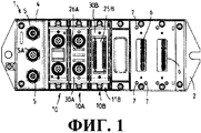
на фиг.1 показан вид сверху контроллера, имеющего панель шины с шестью сменными промежутками и со сменными модулями согласно настоящему изобретению, вставленными в три сменных промежутка;figure 1 shows a top view of a controller having a bus panel with six interchangeable spaces and with interchangeable modules according to the present invention inserted into three interchangeable spaces;
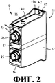
на фиг.2 показан вид в перспективе предпочтительного усовершенствования сменного модуля согласно настоящему изобретению;figure 2 shows a perspective view of a preferred improvement of the plug-in module according to the present invention;
на фиг.3 показан вид сменного модуля по фиг.2 с разнесенными в пространстве деталями;figure 3 shows a view of the removable module of figure 2 with spaced apart parts;
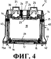
на фиг.4 показан продольный разрез сменного модуля на фиг.3; иfigure 4 shows a longitudinal section of a removable module in figure 3; and
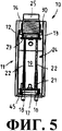
на фиг.5 показан сменный модуль на фиг.2 в разрезе, параллельном боковым стенкам.Fig. 5 shows a plug-in module in Fig. 2 in a section parallel to the side walls.
На фиг.1 показан значительно упрощенный схематичный вид сверху контроллера, в котором предпочтительно использованы сменные модули согласно настоящему изобретению, и который спроектирован, в частности, для использования в передвижных горных комбайнах, которые используются в зонах, которые подвержены угрозам взрывов. Контроллер 1 содержит пластину 2 основания, например, выполненную из нержавеющей стали, на которой соединительная панель или панель 3 шины, в данном случае, с шестью сменными промежутками 6 зафиксирована соответствующим образом. Панель шины 3 снабжена проводниками и электронными элементами (не показано), при этом отдельные сменные промежутки 6 соединены с клеммной колодкой 4, которая, в данном случае, размещена по центру на одной стороне пластины 2 основания контроллера 1. В данном случае клеммная колодка 4 имеет три круглых разъема 5, 5А, причем, возможно, что один круглый разъем 5 образует сетевой вход, один круглый разъем 5 образует сетевой выход и третий круглый разъем 5А образует соединение питания для электрического напряжения, в частности, по существу безопасного напряжения постоянного тока. Три сменных модуля 10, 10А, 10В согласно данному варианту настоящего изобретения уже вставлены в три сменных промежутка 6 в панели шины 3 контроллера 1, при этом сменные модули 10, 10А, 10В, в целом, имеют одну и ту же конструкцию, но обеспечены разными функциональными возможностями, и имеющими немного разные сигнальные устройства или соединительные разъемы. Каждый сменный промежуток 6 предпочтительно снабжен множеством неравномерно распределенных установочных отверстий 7 для предотвращения неправильного монтажа сменного модуля 10, 10А, 10В. Конструкция сменных модулей 10, 10А, 10В ниже объяснена со ссылкой, в частности, на фиг.2-5, на которых подробно проиллюстрирован сменный модуль 10.Figure 1 shows a significantly simplified schematic top view of the controller, which preferably uses plug-in modules according to the present invention, and which is designed, in particular, for use in mobile mining combines, which are used in areas that are subject to explosion threats. The
Сменный модуль 10 имеет интегральный пластмассовый корпус 11, который предпочтительно изготовлен с использованием процесса литья под давлением и имеет переднюю стенку 12, заднюю стенку 13, две боковые стенки 14 и выполненную заодно пластину 15 основания, при этом пластмассовый корпус предпочтительно выполнен в виде коробки. Пластина 15 основания снабжена вырезом 16, в пределах которого соединительный разъем 17 является свободно доступным таким образом, что соединительный разъем 17 удерживается в сменном промежутке 6 (фиг.1), который выполнен на контроллере 1 (фиг.1), когда сменный модуль 10 соединен с контроллером. Соединительный разъем 17 предпочтительно асимметрично смещен по отношению к передней стенке 12 или задней стенке 13, так что сменный модуль 10 может быть установлен на контроллере только с одной ориентацией для обеспечения разъемного соединения между соединительным разъемом 17 и соответствующим сменным промежутком. Для предотвращения неправильного монтажа и обеспечения надежного выполнения разъемного соединения на пластине 16 основания могут быть интегрально выполнены установочные штифты 18, которые могут быть блокирующим образом вставлены в установочные отверстия 7 (фиг.1) для каждого сменного промежутка.The
В приведенном в качестве примера показанном варианте осуществления настоящего изобретения соединительный разъем 17 плотно припаян к нижней торцевой панели 21, которая вместе с двумя боковыми панелями 22 и торцевой панелью 23 образует панельную коробку 24, которая может быть полностью размещена во внутреннем пространстве 19 пластмассового корпуса. В результате, вся система электронной аппаратуры снабжена прочной и жесткой к изгибу конструкцией вследствие конструкции типа панельной коробки с торцевыми панелями 23, которые усилены посредством боковых панелей 22. Боковые панели 22 и торцевые панели 21, 23 вставлены одна в другую с образованием панельной коробки 24, с этой целью боковые панели 22 имеют выступы, которые проходят через пазы в торцевых панелях и могут быть сболчены к выступающему участку выступа. Соединительные контакты двух гнезд 25 разъемов соединены, в частности, припаяны, ко вторым, верхним торцевым панелям 23, которые составлены из металлических круглых гнезд разъемов в приведенном в качестве примера показанном варианте осуществления настоящего изобретения. В каждом случае соседние панели, например, нижние торцевые панели 21 и боковые панели 22 или боковые панели 22 с верхними торцевыми панелями 23 соединены друг с другом посредством гибких проводников (не показано), и поэтому вся управляющая и переключающая электронная аппаратура, которая встроена в сменный модуль 10, может быть размещена распределенным образом по панелям 21, 22, 23 с любыми требуемыми функциями. В отношении этой конструкции также есть возможность соотнести идентичные торцевые панели 21, 23 с разными боковыми панелями 22, для того чтобы экономичным образом адаптировать каждый сменный модуль к его функциональным возможностям. Кроме того, индикаторные элементы 26 для простого отслеживания функций или сигнальные блоки 27 для визуализации текста или значений могут быть соединены с панелью 23 для гнезд 25 разъемов.In an exemplary embodiment shown, the
На фиг.3-5 показаны два гнезда 25 разъемов, прикрепленные к U-образно изогнутой детали 30 из листового металла, которая для фиксирования круглых гнезд 25 снабжена двумя принимающими отверстиями 31, которые в данном случае являются овальными. В приведенном варианте осуществления настоящего изобретения круглые гнезда 25 привинчены только опосредованно к центральному участку 32 изогнутой детали 30 из листового металла, при этом каждое гнездо 25 имеет резьбовой удлинитель 28, на который навинчивают крепежную гайку 29 с другой стороны изогнутой детали 30, для того чтобы прикрепить круглые гнезда 25 к изогнутой детали 30 стойким к растяжению и вращательно неподвижным образом. Центральный участок 32 изогнутой детали 30 соединен с соответствующим торцевым участком 33, который изогнут под прямым углом и привинчен к боковым стенкам 14 пластмассового корпуса 11 посредством резьбовых отверстий 34 в торцевом участке 33 и посредством крепежных винтов 35 в собранном состоянии. Поскольку соединительные гнезда 25 привинчены к изогнутой детали 30, в свою очередь, привинченной к пластмассовому корпусу 11, изогнутая деталь 30 может образовывать зажим с компенсатором натяжения, который предотвращает перенос усилий, воздействующих на сменные модули проводами, которые подсоединены к соединительным гнездам 25, на электронные панели. Центральный участок 32 размещен по центру между двумя принимающими отверстиями 31, с окошком 36, которое в данном случае является прямоугольным, так что индикаторные элементы 26, 27 открыты и видимы на верхней стороне сменного модуля 10.FIGS. 3-5 show two
Для придания дополнительной жесткости пластмассовому корпусу 11 L-образные соединительные скобы 40 свободно привинчены с наружной стороны к двум торцевым поверхностям 14 посредством крепежных винтов 35. В каждом случае один согнутый короткий участок 41 скоб 40 имеет проходное отверстие 42 для блокировочного винта, посредством которого сменный модуль 10 может быть привинчен к пластине основания 2 (фиг.1) контроллера. Пластина 15 основания пластмассового корпуса 1 выступает вбок за боковые стенки 14 пластмассового корпуса 11 крепежными перегородками 15А, причем участки 41 скоб расположены параллельно перед крепежными перегородками 15А в собранном состоянии. Часть длинного участка соединительных скоб 40 имеет проходное отверстие для крепежного винта 35. Таким образом, все усилия натяжения могут быть введены в пластину основания контроллера непосредственного через зажим с компенсатором натяжения, который образован изогнутой деталью 30 из листового металла, при этом соединительные скобы 40 и все внутренние фиттинги в сменных модулях 10, включая пластмассовый корпус, не подвержены действию этих усилий в собранном состоянии.In order to provide additional rigidity to the
В собранном состоянии гнезда 25 разъемов выступают, как можно видеть на фиг.4 и 5, за верхнюю сторону боковых стенок 14, переднюю стенку 12 и заднюю стенку 13 пластмассового корпуса. Уплотнение 45 размещено под пластиной 15 основания пластмассового корпуса 11 и окружает вырез 16 и соединительный разъем 17 для предотвращения попадания влаги в собранном состоянии. Все внутреннее пространство 19 сменного модуля 10 предпочтительно заполнено компаундом герметизации или т.п., для дополнительного усиления сменного модуля 10 и соответствия требованиям классов защиты, таких как IP65 или IP68.In the assembled state, the socket jacks 25 protrude, as can be seen in FIGS. 4 and 5, beyond the upper side of the
Сменный модуль 10А, показанный на фиг.1, имеет такую же внутреннюю конструкцию, как и сменный модуль 10, но отличается, например, электронной аппаратурой, размещенной на панелях, выбором разных индикаторных элементов 26А, в данном случае три индикаторных элемента, которые идентичны друг другу, при этом каждый проходит через отдельное окошко в зажиме 30А с компенсатором натяжения. Сменный модуль 10В также имеет такую же конструкцию, как и сменный модуль 10, в частности внутри корпуса 11В, но отличается, например, электронной аппаратурой, размещенной на панелях, и наличием только одного плоского гнезда 25В, которое проходит через единственное окошко в зажиме 30В с компенсатором натяжения.The plug-in
Многочисленные изменения в объеме приложенной формулы изобретения являются очевидными для специалиста в данной области техники из вышеприведенного описания. Вместо показанных круглых гнезд и/или индикаторного средства, плоское гнездо может быть размещено на верхней стороне сменного модуля, и/или индикаторные элементы могут быть распределены или выполнены по-разному, в частности, если сменный модуль не спроектирован для по существу безопасной работы. Сменный модуль также может иметь меньше или больше двух гнезд разъемов. Корпус также может быть составлен из материалов, отличных от пластмассы, хотя пластмассовый корпус является предпочтительным.Numerous changes in the scope of the attached claims are obvious to a person skilled in the art from the above description. Instead of the circular sockets and / or indicator means shown, a flat socket can be placed on the upper side of the plug-in module, and / or indicator elements can be distributed or made differently, in particular if the plug-in module is not designed for essentially safe operation. A plug-in module can also have fewer or more than two socket slots. The housing may also be composed of materials other than plastic, although a plastic housing is preferred.
Claims (13)
Applications Claiming Priority (3)
| Application Number | Priority Date | Filing Date | Title |
|---|---|---|---|
| DE202009014865.3 | 2009-12-16 | ||
| DE202009014865U DE202009014865U1 (en) | 2009-12-16 | 2009-12-16 | Plug-in module for control units of mobile machines |
| PCT/IB2010/055814 WO2011073909A2 (en) | 2009-12-16 | 2010-12-14 | Plug-in module for controllers of mobile working machines |
Publications (2)
| Publication Number | Publication Date |
|---|---|
| RU2012129891A RU2012129891A (en) | 2014-01-27 |
| RU2552103C2 true RU2552103C2 (en) | 2015-06-10 |
Family
ID=43927366
Family Applications (1)
| Application Number | Title | Priority Date | Filing Date |
|---|---|---|---|
| RU2012129891/07A RU2552103C2 (en) | 2009-12-16 | 2010-12-14 | Replaceable module for moving miner controllers |
Country Status (11)
| Country | Link |
|---|---|
| US (1) | US8885358B2 (en) |
| EP (1) | EP2514289B1 (en) |
| CN (1) | CN102742373B (en) |
| AU (1) | AU2010331849B2 (en) |
| DE (1) | DE202009014865U1 (en) |
| MX (1) | MX2012006722A (en) |
| PL (1) | PL2514289T3 (en) |
| RU (1) | RU2552103C2 (en) |
| UA (1) | UA108367C2 (en) |
| WO (1) | WO2011073909A2 (en) |
| ZA (1) | ZA201205175B (en) |
Families Citing this family (7)
| Publication number | Priority date | Publication date | Assignee | Title |
|---|---|---|---|---|
| JP1519665S (en) * | 2014-05-30 | 2015-03-23 | ||
| DE102014110278B4 (en) * | 2014-07-22 | 2018-08-30 | Harting Electric Gmbh & Co. Kg | Support frame for connector modules and / or connectors |
| USD835099S1 (en) * | 2016-08-26 | 2018-12-04 | Sciemetric Instruments Inc. | Data acquisition module |
| DE102018101779A1 (en) * | 2018-01-26 | 2019-08-01 | Phoenix Contact Gmbh & Co. Kg | Connectors and electronic device |
| CN116940032A (en) * | 2022-03-31 | 2023-10-24 | 亿咖通(湖北)技术有限公司 | Control device and vehicle |
| EP4312473B1 (en) * | 2022-07-28 | 2024-08-28 | Siemens Aktiengesellschaft | Modular automation system |
| CN116437617B (en) * | 2023-04-11 | 2024-08-20 | 小米汽车科技有限公司 | On-board controller and vehicle |
Citations (3)
| Publication number | Priority date | Publication date | Assignee | Title |
|---|---|---|---|---|
| US4715822A (en) * | 1985-07-13 | 1987-12-29 | Stribel Gmbh | Electrical connection device for a motor vehicle |
| RU691U1 (en) * | 1994-01-05 | 1995-08-16 | Акционерное общество открытого типа "Автоэлектроарматура" | Electric multi-function mounting block |
| RU54285U1 (en) * | 2005-01-31 | 2006-06-10 | Открытое акционерное общество "Научно-конструкторское бюро вычислительных систем" (ОАО НКБ ВС) | AUTOMATIC TELEVISION |
Family Cites Families (16)
| Publication number | Priority date | Publication date | Assignee | Title |
|---|---|---|---|---|
| US4158757A (en) * | 1978-02-15 | 1979-06-19 | Allen-Bradley Company | Enclosure seal |
| US5428535A (en) * | 1992-09-17 | 1995-06-27 | Kansei Corporation | Vehicle control unit structure |
| US5501605A (en) * | 1993-06-07 | 1996-03-26 | Yazaki Corporation | Wiring harness assembly for vehicles |
| US5708568A (en) * | 1996-06-17 | 1998-01-13 | Sundstrand Corporation | Electronic module with low impedance ground connection using flexible circuits |
| DE19741047C2 (en) * | 1997-09-18 | 2002-11-14 | Conti Temic Microelectronic | Electronic ignition lock for motor vehicles |
| BR9807925A (en) * | 1998-02-05 | 2000-02-22 | Bosch Gmbh Robert | Electronic module for a drive unit operated by an electric motor |
| DE19925738B4 (en) * | 1999-06-07 | 2017-02-09 | Caterpillar Global Mining Europe Gmbh | Control unit for electrohydraulic control systems |
| DE20214132U1 (en) * | 2002-09-12 | 2002-12-05 | HARTING Electric GmbH & Co. KG, 32339 Espelkamp | connector module |
| CN2596413Y (en) * | 2003-01-08 | 2003-12-31 | 毛磊 | Device for increasing external interface on computer casing front surface |
| US20060120083A1 (en) * | 2004-12-08 | 2006-06-08 | Automatic Power, Inc. | Dual LED point-source assembly |
| DE102005052777A1 (en) * | 2005-11-04 | 2007-05-24 | Amrona Ag | Device for detecting fire in control cabinets |
| US7230833B1 (en) * | 2006-04-04 | 2007-06-12 | Daniel Industries, Inc. | Electronics module retention system |
| US7753740B2 (en) | 2007-07-20 | 2010-07-13 | Numatics, Incorporated | Modular electrical bus system |
| DE102007038054A1 (en) * | 2007-08-10 | 2009-02-26 | Vega Grieshaber Kg | Multi-part board |
| DE102008025938A1 (en) | 2008-05-30 | 2009-12-03 | Continental Automotive Gmbh | Printed circuit board arrangement for control unit of internal combustion engine of motor vehicle, has plug connectors conductive coupled with related rigid regions and positioned adjacent to one another to form common plug connector unit |
| US8360390B2 (en) * | 2009-01-13 | 2013-01-29 | Enphase Energy, Inc. | Method and apparatus for potting an electronic device |
-
2009
- 2009-12-16 DE DE202009014865U patent/DE202009014865U1/en not_active Expired - Lifetime
-
2010
- 2010-12-14 RU RU2012129891/07A patent/RU2552103C2/en active
- 2010-12-14 PL PL10812907T patent/PL2514289T3/en unknown
- 2010-12-14 WO PCT/IB2010/055814 patent/WO2011073909A2/en not_active Ceased
- 2010-12-14 CN CN201080056928.1A patent/CN102742373B/en not_active Expired - Fee Related
- 2010-12-14 EP EP10812907.3A patent/EP2514289B1/en active Active
- 2010-12-14 MX MX2012006722A patent/MX2012006722A/en active IP Right Grant
- 2010-12-14 US US13/516,487 patent/US8885358B2/en active Active
- 2010-12-14 UA UAA201208702A patent/UA108367C2/en unknown
- 2010-12-14 AU AU2010331849A patent/AU2010331849B2/en active Active
-
2012
- 2012-07-12 ZA ZA2012/05175A patent/ZA201205175B/en unknown
Patent Citations (3)
| Publication number | Priority date | Publication date | Assignee | Title |
|---|---|---|---|---|
| US4715822A (en) * | 1985-07-13 | 1987-12-29 | Stribel Gmbh | Electrical connection device for a motor vehicle |
| RU691U1 (en) * | 1994-01-05 | 1995-08-16 | Акционерное общество открытого типа "Автоэлектроарматура" | Electric multi-function mounting block |
| RU54285U1 (en) * | 2005-01-31 | 2006-06-10 | Открытое акционерное общество "Научно-конструкторское бюро вычислительных систем" (ОАО НКБ ВС) | AUTOMATIC TELEVISION |
Also Published As
| Publication number | Publication date |
|---|---|
| DE202009014865U1 (en) | 2011-04-28 |
| EP2514289B1 (en) | 2018-09-12 |
| RU2012129891A (en) | 2014-01-27 |
| WO2011073909A3 (en) | 2011-08-11 |
| US20120327619A1 (en) | 2012-12-27 |
| AU2010331849B2 (en) | 2016-04-28 |
| ZA201205175B (en) | 2013-05-29 |
| PL2514289T3 (en) | 2019-01-31 |
| AU2010331849A1 (en) | 2012-06-14 |
| EP2514289A2 (en) | 2012-10-24 |
| US8885358B2 (en) | 2014-11-11 |
| CN102742373A (en) | 2012-10-17 |
| MX2012006722A (en) | 2012-10-15 |
| WO2011073909A2 (en) | 2011-06-23 |
| CN102742373B (en) | 2015-04-15 |
| UA108367C2 (en) | 2015-04-27 |
Similar Documents
| Publication | Publication Date | Title |
|---|---|---|
| RU2552103C2 (en) | Replaceable module for moving miner controllers | |
| US7192316B1 (en) | Electrical connecting terminal | |
| JP6551980B2 (en) | Surge protection device and surge protection system | |
| US9451712B2 (en) | Series module arrangement with an energy bus system | |
| US8904710B2 (en) | Door drive | |
| CA2934044A1 (en) | Slide lock for circuit boards | |
| RU2301340C2 (en) | Device for individually controlling sections of mechanized shield lining | |
| RU2302530C2 (en) | Electrohydraulic control device | |
| RU2017973C1 (en) | Control device for walking support hydraulic devices | |
| WO2013105674A2 (en) | Screw block installation structure for a junction box | |
| US20080256862A1 (en) | Device for Opening and/or Closing a Door | |
| US20060264118A1 (en) | Control device for electrohydraulic support controller | |
| RU2541507C2 (en) | System connecting single row casing with connecting element | |
| TR201808164T4 (en) | A mechanism for connecting electrical illuminators with a fault current collector. | |
| CN113555731B (en) | Busbar structure and conductive device | |
| RU192718U1 (en) | Electronic device module | |
| CN201937996U (en) | Programmable logic controller (PLC) control cabinet for mine | |
| CN201174582Y (en) | Motor protection controller and transducer | |
| CN106058510A (en) | Electrical inspection grounding interface general device | |
| KR200421649Y1 (en) | Terminal block | |
| JP6590279B2 (en) | lighting equipment | |
| JP2013187038A (en) | Lighting fixture | |
| CA2587575A1 (en) | Security surveillance system for electronic device | |
| KR200490639Y1 (en) | Ac lighting device where earth is embedded | |
| RU2432720C1 (en) | Radio-electronic unit |