RU2552083C2 - Centrifugal compression of moist gas or expansion with device of protection against liquid piston and/or spray device - Google Patents
Centrifugal compression of moist gas or expansion with device of protection against liquid piston and/or spray device Download PDFInfo
- Publication number
- RU2552083C2 RU2552083C2 RU2012126170/13A RU2012126170A RU2552083C2 RU 2552083 C2 RU2552083 C2 RU 2552083C2 RU 2012126170/13 A RU2012126170/13 A RU 2012126170/13A RU 2012126170 A RU2012126170 A RU 2012126170A RU 2552083 C2 RU2552083 C2 RU 2552083C2
- Authority
- RU
- Russia
- Prior art keywords
- spray
- gas
- liquid
- piston
- multiphase fluid
- Prior art date
Links
Images
Classifications
-
- F—MECHANICAL ENGINEERING; LIGHTING; HEATING; WEAPONS; BLASTING
- F04—POSITIVE - DISPLACEMENT MACHINES FOR LIQUIDS; PUMPS FOR LIQUIDS OR ELASTIC FLUIDS
- F04D—NON-POSITIVE-DISPLACEMENT PUMPS
- F04D29/00—Details, component parts, or accessories
- F04D29/58—Cooling; Heating; Diminishing heat transfer
- F04D29/582—Cooling; Heating; Diminishing heat transfer specially adapted for elastic fluid pumps
- F04D29/5846—Cooling; Heating; Diminishing heat transfer specially adapted for elastic fluid pumps cooling by injection
-
- F—MECHANICAL ENGINEERING; LIGHTING; HEATING; WEAPONS; BLASTING
- F04—POSITIVE - DISPLACEMENT MACHINES FOR LIQUIDS; PUMPS FOR LIQUIDS OR ELASTIC FLUIDS
- F04D—NON-POSITIVE-DISPLACEMENT PUMPS
- F04D31/00—Pumping liquids and elastic fluids at the same time
Landscapes
- Engineering & Computer Science (AREA)
- Mechanical Engineering (AREA)
- General Engineering & Computer Science (AREA)
- Physics & Mathematics (AREA)
- Thermal Sciences (AREA)
- Structures Of Non-Positive Displacement Pumps (AREA)
Abstract
Description
Перекрестная ссылка на родственную заявкуCross reference to related application
Данная заявка заявляет преимущество предварительной заявки на патент США 61/264414, поданной 25 ноября 2009 г., озаглавленной «Центробежное сжатие влажного газа или расширение с устройством защиты от поршня и/или распылительным устройством», которая во всей своей полноте приводится здесь в качестве ссылки.This application claims the benefit of provisional application for US
Предпосылки создания изобретенияBACKGROUND OF THE INVENTION
Область техники, к которой относится изобретениеFIELD OF THE INVENTION
Предмет изобретения, рассмотренный в данной заявке, относится к технологии, используемой в сжатии или расширении многофазной текучей среды в системе обработки текучей среды.The subject matter of this application relates to a technology used in compressing or expanding a multiphase fluid in a fluid processing system.
Описание уровня техникиDescription of the prior art
Данный раздел предназначен для введения различных аспектов уровня техники, которые могут быть связаны с типичными вариантами настоящего изобретения. Предполагается, что данное рассмотрение способствует созданию основных принципов для облегчения лучшего понимания частных аспектов настоящего изобретения. Соответственно, должно быть понятно, что данный раздел должен восприниматься в этом свете и необязательно как подходы уровня техники.This section is intended to introduce various aspects of the prior art that may be associated with typical embodiments of the present invention. It is intended that this consideration contribute to the creation of basic principles to facilitate a better understanding of the particular aspects of the present invention. Accordingly, it should be understood that this section should be understood in this light and not necessarily as prior art approaches.
Обычно подразумевается, что центробежные компрессоры или газовые расширители не обрабатывают жидкие поршни, и, таким образом, принимается, что они могут обрабатывать только фракцию одного процента жидкости по объему. Таким образом, во многих применениях дорогостоящие сепараторы жидкости, способы дегидратации и/или установки скрубберов используются для испытания и удаления или отделения жидкостей перед использованием центробежных компрессоров или расширителей. Указанные устройства часто предназначены для специальных рабочих условий и поэтому ограничены интервалом газовой объемной фракции ((ГОФ) (GVF)), которая может подаваться с заданной скоростью технологического потока. Даже с указанным дорогостоящим и сложным перерабатывающим оборудованием, если имеется неожиданно высокий уровень жидкостей, они могут быстро насыщать, заполнять и переливать сепараторы жидкости, как только их емкость для жидкости превышается, что приводит к поршневому движению (образованию пробки) в компрессорном или расширительном оборудовании.It is generally understood that centrifugal compressors or gas expanders do not process liquid pistons, and thus it is accepted that they can only process a fraction of one percent liquid by volume. Thus, in many applications, expensive liquid separators, dehydration methods, and / or scrubber installations are used to test and remove or separate liquids before using centrifugal compressors or expanders. These devices are often designed for special operating conditions and therefore are limited by the interval of the gas volume fraction ((GOF) (GVF)), which can be supplied at a given speed of the process stream. Even with the indicated expensive and complex processing equipment, if there is an unexpectedly high level of liquids, they can quickly saturate, fill and overfill the liquid separators as soon as their liquid capacity is exceeded, which leads to piston movement (plugging) in the compressor or expansion equipment.
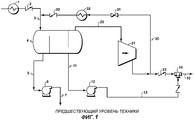
Обычно могут использоваться многофазные насосы, если известно, что текучая среда будет обычно ниже 90% ГОФ. Центробежные компрессоры часто ограничиваются в применениях ГОФ 99,7 или выше, и даже это может вызвать проблемы в машине в отношении стабильности и повлиять на надежность уплотнений и подшипников. Поэтому для процессов вне указанного небольшого интервала современная практика состоит в разделении текучих сред перед использованием центробежного компрессора даже с разработанным ограничением с соответствующими способом и оборудованием. То же самое справедливо для газовых расширителей, которые представляют собой функционально центробежный компрессор, который наоборот высвобождает энергию в одной форме или другой при падении давления процесса в расширителе. Сепараторы, скрубберы и установки дегидратации являются не только дорогостоящими и ограниченными по объему жидкости и интервалу объемного потока, но они также имеют тенденцию быть громоздкими, обеспечивая дорогостоящее недвижимое имущество в таких местах, как морские платформы, подводная переработка или оборудование прибрежных участков. Указанное в сочетании со сложными системами контроля и дополнительным вспомогательным оборудованием, подобным насосам, регуляторам, контроллерам уровня, передающим устройствам и фильтрам, увеличивает сложность и вероятность отказа указанных систем. Пример способа, где поршни (пробки) могут вызвать сильное повреждение, показан на фигуре 1, на которой показано обслуживание типичной нефтяной или газовой скважины, где сепаратор 4 используется для отделения жидкости от газа, так что центробежный компрессор 21 и насос 12 могут затем использоваться для нагнетания газа и жидкости раздельно. Газ и жидкость затем объединяются снова под ссылочной позицией 14 для того, чтобы транспортироваться вместе по трубопроводу к перерабатывающему оборудованию. Если одна машина может использоваться для транспортирования объединенного потока, это потенциально значительно снижает общую стоимость и сложность всей системы.Multiphase pumps can usually be used if it is known that the fluid will typically be below 90% GOF. Centrifugal compressors are often limited in applications of GOF 99.7 or higher, and even this can cause problems in the machine with regard to stability and affect the reliability of seals and bearings. Therefore, for processes outside the specified small interval, current practice is to separate fluids before using a centrifugal compressor, even with the developed restriction with the appropriate method and equipment. The same is true for gas expanders, which are a functionally centrifugal compressor, which, on the contrary, releases energy in one form or another when the process pressure in the expander drops. Separators, scrubbers, and dehydration plants are not only expensive and limited in terms of fluid volume and volumetric flow interval, but they also tend to be cumbersome, providing expensive real estate in places such as offshore platforms, underwater processing or offshore equipment. Indicated in conjunction with sophisticated control systems and additional accessories such as pumps, regulators, level controllers, transmitters and filters, increases the complexity and probability of failure of these systems. An example of a method where the pistons (plugs) can cause severe damage is shown in Figure 1, which shows the maintenance of a typical oil or gas well, where a separator 4 is used to separate the liquid from the gas, so that the
Некоторыми дополнительными вопросами, связанными с жидкостями, являются не только стабильность машины, но также эрозия крыльчаток и распылителей, засорение и получаемый дисбаланс, если жидкости испаряются или выпариваются при сжатии в машине. Однако было показано, что эрозия может быть снижена или предотвращена замедлением скорости жидкости в точках соударения и снижением размера капель. Засорение также может быть снижено или даже устранено при увеличении уровней жидкости выше точки испарения в эффективной промывке внутренних частей машины.Some additional issues related to liquids are not only the stability of the machine, but also the erosion of the impellers and nozzles, clogging and the resulting imbalance if the liquids evaporate or evaporate when compressed in a machine. However, it has been shown that erosion can be reduced or prevented by slowing the fluid velocity at the collision points and reducing droplet size. Clogging can also be reduced or even eliminated by increasing liquid levels above the evaporation point in an effective flushing of the inside of the machine.
Приведенное выше рассмотрение потребности техники предназначено быть скорее представительным, чем исчерпывающим. Технология, которая будет улучшать способность компрессоров или расширителей обрабатывать многофазный поток текучей среды с более высоким содержанием жидкости по сравнению с современным уровнем техники, будет иметь большое значение.The above consideration of the need for technology is intended to be representative rather than exhaustive. A technology that will improve the ability of compressors or expanders to process a multiphase fluid stream with a higher liquid content than current technology will be of great importance.
Краткое описание изобретенияSUMMARY OF THE INVENTION
Отмеченные выше проблемы в обработке потока многофазной текучей среды адресованы использованию устройства защиты от жидкого поршня и/или распылительного устройства для улучшения смешения выше по потоку жидкости с газом, таким образом давая возможность центробежному компрессору или расширителю лучше обрабатывать более высокие уровни жидкости. Распылительным устройством может быть любой из известных распылителей текучей среды или устройство смешения потока. Это может быть использовано в существующих разработках для способствования защите компрессора или расширителя от сбоев способа с дополнительным объемом жидкости или в качестве установленной единственной конструкции для способствования исключения части требуемого оборудования, такого как сепаратор или насос жидкости.The problems noted above in the processing of a multiphase fluid stream are addressed using a liquid piston protection device and / or a spray device to improve mixing upstream of the liquid with the gas, thereby enabling a centrifugal compressor or expander to better handle higher liquid levels. The spray device may be any of the known fluid spray devices or a flow mixing device. This can be used in existing designs to help protect the compressor or expander from process failures with an additional volume of liquid, or as an established single design to help exclude parts of the required equipment, such as a separator or liquid pump.
Устройство защиты от жидкого поршня (пробки) замедляет жидкий поршень и смешивает жидкость с газом уже в устройстве со снижением резкого изменения плотности. Это обеспечивает время для замедления двигателя компрессора, т.к. крутящий момент или нагрузка увеличивается с увеличением объема жидкости или снижением ГОФ. Распылительное устройство, кроме того, способствует превращению жидких поршней (пробок) в капли или туман, смешанные с газом, с лучшим содействием компрессору справиться с резким изменением плотности и нагрузки при снижении удара, что дает меньшую эрозию. Либо продукт, либо оба последовательно могут использоваться в применении компрессора или расширителя, где имеется возможность сбоев некоторых жидкостей или жидкости.The device for protection against a liquid piston (plug) slows down the liquid piston and mixes the liquid with gas already in the device with a decrease in a sharp change in density. This provides time to slow the compressor motor, as Torque or load increases with increasing fluid volume or lower GOF. In addition, the spray device helps to transform liquid pistons (plugs) into droplets or fog mixed with gas, with the best assistance of the compressor, to cope with a sharp change in density and load while reducing impact, which gives less erosion. Either the product or both can be used sequentially in the use of a compressor or expander, where there is the possibility of failure of some liquids or liquids.
В контексте данного рассмотрения термин «распылительное устройство» означает любое устройство или механизм для расщепления жидкости на дымку, туман или спрей жидкости. Термин «распыленный», как использовано здесь, должен пониматься как означающий мелкие дискретные частицы жидкости. Также термин «устройство защиты от поршня (пробки)» означает любое устройство, которое способствует замедлению резкого изменения плотности текучей среды с высоким уровнем жидкости в газовом потоке при смешении предопределенного потока жидкости с газом, который течет впереди, вместе с или позади жидкости.In the context of this discussion, the term "spray device" means any device or mechanism for splitting a liquid into a haze, fog, or spray of liquid. The term "sprayed", as used here, should be understood as meaning small discrete particles of liquid. Also, the term "piston protection device (plug)" means any device that helps to slow down a sharp change in the density of a fluid with a high level of liquid in the gas stream by mixing a predetermined liquid stream with the gas that flows in front, along with or behind the liquid.
Вышеприведенное довольно широко отмечает характеристики и технические преимущества настоящего изобретения для того, чтобы могло быть лучше понято подробное описание изобретения, которое следует далее. Далее будут описаны дополнительные характеристики и преимущества изобретения, которые образуют объект формулы изобретения. Специалисты в данной области техники отметят, что рассмотренные концепция и отдельный вариант могут быть легко использованы в качестве основы для модификации или разработки других структур для осуществления тех же самых целей настоящего изобретения. Также должно быть понято специалистами в данной области техники, что такие эквивалентные конструкции не отходят от сущности и объема изобретения, как представлено в прилагаемой формуле изобретения.The above quite broadly notes the characteristics and technical advantages of the present invention in order to better understand the detailed description of the invention that follows. Next will be described additional characteristics and advantages of the invention, which form the subject of the claims. Those skilled in the art will recognize that the concept and separate embodiment discussed above can easily be used as the basis for modifying or developing other structures to accomplish the same objectives of the present invention. It should also be understood by experts in the field of technology that such equivalent constructions do not depart from the essence and scope of the invention, as presented in the attached claims.
Краткое описание нескольких видов чертежейA brief description of several types of drawings
Новые характеристики, которые считаются характеристиками изобретения, как для его организации, так и способа работы вместе с другими объектами и преимуществами будут лучше поняты из последующего описания при рассмотрении в сочетании с сопровождающими чертежами. Однако должно быть ясно понятно, что каждый из чертежей представлен только в целях иллюстрации и описания и не предназначен для определения пределов настоящего изобретения.New features that are considered characteristics of the invention, both for its organization and the way it works together with other objects and advantages will be better understood from the following description when considered in conjunction with the accompanying drawings. However, it should be clearly understood that each of the drawings is presented for purposes of illustration and description only and is not intended to define the scope of the present invention.
На фигуре 1 представлена схема известной системы обработки многофазной текучей среды.The figure 1 presents a diagram of a known system for processing a multiphase fluid.
На фигуре 2 представлена схема одного варианта системы обработки многофазной текучей среды согласно изобретению для сжатия многофазной текучей среды.2 is a diagram of one embodiment of a multiphase fluid processing system according to the invention for compressing a multiphase fluid.
На фигуре 3 представлена схема другого варианта системы обработки многофазной текучей среды согласно изобретению для расширения многофазной текучей среды.3 is a diagram of another embodiment of a multiphase fluid processing system according to the invention for expanding a multiphase fluid.
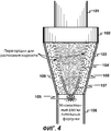
На фигуре 4 представлена схема объединенных устройства защиты от поршня и распылительного устройства.4 is a diagram of a combined piston protection device and a spray device.
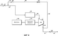
На фигуре 5 представлен модифицированный вариант системы обработки многофазной текучей среды, показанной на фигуре 2.Figure 5 shows a modified version of the multiphase fluid processing system shown in Figure 2.
Должно быть отмечено, что чертежи являются только примерами нескольких вариантов настоящего изобретения и поэтому не предназначены для ограничения объема настоящего изобретения. Кроме того, чертежи обычно не выполнены в масштабе, но выполнены в целях удобства и ясности в показе различных аспектов изобретения.It should be noted that the drawings are only examples of several variants of the present invention and therefore are not intended to limit the scope of the present invention. In addition, the drawings are usually not made to scale, but are made for convenience and clarity in showing various aspects of the invention.
Подробное описание изобретенияDETAILED DESCRIPTION OF THE INVENTION
Ссылка теперь делается на типичные варианты и специальный язык, используемый для их описания. Однако понятно, что поэтому никакого ограничения объема изобретения не подразумевается. Изменения других модификаций характеристик изобретения, описанных здесь, и дополнительные применения принципов изобретения, как описано здесь, которые будут иметься у специалиста в данной области техники, имеющего в своем распоряжении данное описание, должны считаться находящимися в объеме изобретения. Кроме того, прежде чем рассмотрены и описаны частные варианты настоящего изобретения, должно быть понятно, что данное изобретение не ограничивается частным способом и материалами, рассмотренными здесь, т.к. они могут варьироваться в некоторой степени. Также должно быть понятно, что используемая здесь терминология используется только в целях описания частных вариантов и не предназначена быть ограничивающей, т.к. объем настоящего изобретения определяется только прилагаемой формулой изобретения и ее эквивалентами.Reference is now made to typical options and the special language used to describe them. However, it is understood that therefore, no limitation on the scope of the invention is implied. Changes to other modifications of the characteristics of the invention described herein, and additional applications of the principles of the invention, as described herein, which will be available to those skilled in the art having this description, should be considered within the scope of the invention. In addition, before considering and describing particular embodiments of the present invention, it should be understood that the present invention is not limited to the particular method and materials discussed herein, since they may vary to some extent. It should also be clear that the terminology used here is used only to describe particular options and is not intended to be limiting, because The scope of the present invention is determined only by the attached claims and their equivalents.
На фигуре 1 показана известная система обработки многофазной текучей среды в условиях работы устья скважины. Текучая среда, которая может содержать, например, воду, нефть и газ, направляется в охлаждающее устройство 1 и затем в разделительный резервуар 4 через контрольный клапан 2 и трубопровод 3. Вода отделяется, и насос 6 подает воду в удаленное местонахождение по трубопроводу 7. Нефть и конденсат собираются, и насос 12 подает нефть и конденсат в трубопровод 15 через трубопроводы 11 и 13. Газ идет из сепаратора 4 в компрессор 21 по трубопроводу 20, затем он проходит через контрольный клапан 23 и объединяется с потоком нефть/конденсат под ссылочной позицией 14. Предусматривается линия 30 рециклирования, которая содержит клапан 31, охлаждающее устройство 32 и контрольный клапан 33.The figure 1 shows a well-known system for processing multiphase fluid in the working conditions of the wellhead. A fluid, which may contain, for example, water, oil and gas, is sent to a cooling device 1 and then to a separation tank 4 through a control valve 2 and a pipe 3. The water is separated and the
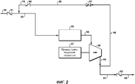
Принципы изобретения показаны в одном варианте, как схематически представлено на фигуре 2. Многофазная текучая среда, например текучая среда из устья скважины, направляется в устройство по трубопроводу 50, контрольному клапану 51 и трубопроводу 52. Смесь жидкости и газа поступает в устройство 55 обработки текучей среды. Устройством обработки текучей среды может быть устройство защиты от поршня (пробки) или известное распылительное устройство, такое как одна или более распылительных форсунок или смеситель потока. Им также может быть комбинация указанных элементов. Пример объединенных устройства защиты от поршня и распылительного устройства показан на фигуре 4. Жидкость накапливается во внутренней камере 107, а газ идет в наружную камеру 108. Перегородки 104 предусматриваются на стенках внутренней камеры 107 для обеспечения резких увеличений разлива жидкости в газовом потоке и смешения с газом. Таким образом, резкое увеличение потока жидкости замедляется за счет использовании части газа еще в устройстве защиты от поршня для снижения объема жидкости. Распылительные форсунки 105 на нижнем конце камеры жидкости измельчают жидкость и распыляют ее в газовый поток ниже по потоку от суженной части 109 пути газового потока. Потоки распыленной жидкости и газа продолжают течь через трубопроводную часть 106. Типичное устройство защиты от поршня и распылительное устройство является доступным от Framo Engineering AS. Смеситель потока может включать противозакручивающие лопатки или вихревые камеры с противовращением.The principles of the invention are shown in one embodiment, as schematically represented in Figure 2. Multiphase fluid, for example fluid from a wellhead, is routed to the device through
Что касается снова фигуры 2, смесь, выходящая из устройства 55 обработки текучей среды, течет по трубопроводу 56 в компрессор 58. Сжатая текучая среда выходит из компрессора 58 по трубопроводу 60 и 61 к контрольному клапану 62 и к распределительному трубопроводу 63, который подает сжатую текучую среду к требуемому местоположению. Под ссылочной позицией 66 предусматривается линия рециклирования смеси из компрессора 58, которая содержит клапан 67 и контрольный клапан 69.Referring again to FIG. 2, the mixture exiting the
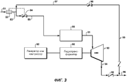
На фигуре 3 показано применение принципов изобретения в расширительной системе. Многофазная текучая среда проходит через многофазный расходомер 82, контрольный клапан 84 и трубопровод 85 в устройство 55 обработки текучей среды, из которого смесь течет через трубопровод 91, расширитель 93, трубопровод 94, контрольный клапан 95 и распределительный трубопровод 96. Расширитель 93 может быть соединен с генератором или компрессором 92 или любым устройством, которое требует источника энергии. Байпасная линия 99, 97 вместе с клапаном 98 предусматривается для обхода расширителя 93. Гидротрансформатор 90 может быть расположен между расширителем 93 и генератором или компрессором 90.Figure 3 shows the application of the principles of the invention in an expansion system. Multiphase fluid passes through a
Комбинирование одного или обоих из устройства защиты от поршня (пробки) и распылительного устройства с регулированием крутящего момента или снижения скорости с увеличенной нагрузкой, уровня жидкости или общей плотности текучей среды будет дополнительно обеспечивать более широкий рабочий интервал для центробежного компрессора или расширителя. Регулирование скорости компрессора, например, может быть достигнуто при использовании привода с регулируемой скоростью, как показано на фигуре 2. Привод 57 с регулируемой скоростью (VSD), такой как мотор или другой механический или электрический двигатель, включая (но не ограничиваясь этим) газовый мотор, паровую или газовую турбину, расширитель, гидравлическую турбину, соединяется с компрессором 58. Приводной механизм, регулирующий крутящий момент или скорость, между приводом и компрессором может быть электронным, гидравлическим или механическим. Подходящие средства регулирования привода с регулируемой скоростью могут включать в себя датчики крутящего момента, нагрузки, плотности текучей среды, ГОФ или входной мощности.The combination of one or both of a piston protection device (plug) and a spray device with torque control or speed reduction with increased load, fluid level or total fluid density will additionally provide a wider operating range for a centrifugal compressor or expander. Compressor speed control, for example, can be achieved by using a variable speed drive, as shown in Figure 2. Variable speed (VSD) drive 57, such as a motor or other mechanical or electric engine, including (but not limited to) a gas motor , a steam or gas turbine, an expander, a hydraulic turbine, is connected to the
Регулирование скорости или крутящего момента помогает сделать компрессоры и расширители более устойчивыми, таким образом увеличивая надежность и снижая стоимость содержания в условиях заправки при разработке системы с лучшим управлением жидкими поршнями и многофазным потоком. Это может быть применено во всех видах применений центробежного компрессора и расширителя, где жидкости присутствуют или потенциально присутствуют в способе, включая обслуживание устья скважины, подводные компрессоры или расширители, расширение СПГ (LNG) (сжиженного природного газа), компрессоры влажного газа и другие способы выше и ниже по потоку.Adjusting speed or torque helps make compressors and expanders more stable, thereby increasing reliability and lowering costs in refueling conditions when designing a system with better fluid piston and multiphase flow control. This can be applied in all types of centrifugal compressor and expander applications where fluids are present or potentially present in the method, including wellhead servicing, subsea compressors or expanders, LNG (LNG) expansion, wet gas compressors and other methods above and downstream.
Вариантом регулирования крутящего момента является использование гидротрансформатора вместо использования USD привода. Затем для привода компрессора могут быть использованы традиционные моторы с фиксированной скоростью, газовые турбины и связанные механические приводы.A torque control option is to use a torque converter instead of using a USD drive. Then, conventional fixed speed motors, gas turbines, and associated mechanical drives can be used to drive the compressor.
Для расширителя регулирование потока может использовать двух- или трехфазный расходомер 82 с работой клапана 84 впускного потока или впускных направляющих лопаток для того, чтобы снизить поток, когда ГОФ падает с увеличенным уровнем жидкости, как показано на фигуре 3. Другими вариантами является использование гидротрансформатора 90 между газовым расширителем 93 и чем он приводится в действие или любой другой способ с измерением плотности текучей среды, многофазной смеси потока, выходной мощности или крутящего момента.For the expander, flow control may use a two- or three-
Как показано на фигуре 5, привод 57 с регулируемой скоростью с фигуры 2 может быть заменен приводом 102 с фиксированной скоростью. Гидротрансформатор 101 может быть расположен между приводом с фиксированной скоростью и компрессором 58, чтобы обеспечивать варьирование скорости компрессора 58.As shown in FIG. 5, the
Настоящее изобретение дополнительно описано в следующих вариантах:The present invention is further described in the following embodiments:
Вариант АOption A
Устройство для сжатия многофазной текучей среды, содержащее:A device for compressing a multiphase fluid, comprising:
первый трубопровод для транспортирования многофазной текучей среды;a first pipeline for transporting multiphase fluid;
устройство защиты от поршня, соединенное с первым трубопроводом;a piston protection device connected to the first pipe;
центробежный компрессор, соединенный с выпуском устройства защиты от поршня; иa centrifugal compressor connected to the outlet of the piston protection device; and
распределительный трубопровод, соединенный с компрессором, для транспортирования сжатой многофазной текучей среды в требуемое местоположение.a distribution pipe connected to a compressor for transporting the compressed multiphase fluid to a desired location.
Вариант ВOption B
Устройство варианта А, дополнительно содержащее распылительное устройство, расположенное в первом трубопроводе.The device of option A, further comprising a spray device located in the first pipe.
Вариант СOption C
Устройство варианта В, в котором распылительное устройство представляет собой смеситель потока, который включает в себя, по меньшей мере, две противозакручивающиеся лопатки или вихревые камеры с противовращением.The device of option B, in which the spray device is a flow mixer, which includes at least two anti-swirl vanes or vortex chambers with counter-rotation.
Вариант DOption D
Устройство любого из вариантов А-С, в котором двигатель для компрессора представляет собой электрический или газовый мотор, газовую или паровую турбину, расширитель, гидравлическую турбину.The device of any of the options AC, in which the engine for the compressor is an electric or gas motor, gas or steam turbine, expander, hydraulic turbine.
Вариант ЕOption E
Устройство любого из вариантов А-D, дополнительно содержащее устройство регулирования скорости компрессора на основе создаваемого крутящего момента, нагрузки, плотности текучей среды, измерения многофазного потока или выходной мощности.A device of any of the AD alternatives, further comprising a compressor speed control device based on the generated torque, load, fluid density, multiphase flow or output power measurement.
Вариант FOption F
Устройство варианта В или С, в котором устройство защиты от поршня и распылительное устройство объединены в корпусе, имеющем впуск и выпуск, в котором корпус содержит:The device of option B or C, in which the piston protection device and the spray device are combined in a housing having an inlet and outlet, in which the housing comprises:
первую камеру для накапливания жидкости;a first fluid storage chamber;
вторую камеру для накапливания газа;a second gas storage chamber;
множество перегородок между первой и второй камерами для обеспечения возможности накопленной жидкости в первой камере разливаться во второй камере; иa plurality of partitions between the first and second chambers to enable the accumulated liquid in the first chamber to spill in the second chamber; and
множество распылительных форсунок, расположенных в концевой части первой камеры.a plurality of spray nozzles located at the end of the first chamber.
Вариант GOption G
Устройство согласно варианту F, в котором корпус сужается от впуска к выпуску.An apparatus according to embodiment F, wherein the housing tapers from inlet to outlet.
Вариант НOption H
Устройство по любому из вариантов A-G, дополнительно содержащее трубопровод рециклирования, соединенный на одном конце с выпуском компрессора и на его другом конце с первым трубопроводом.A device according to any one of embodiments A-G, further comprising a recycling conduit connected at one end to a compressor outlet and at its other end to a first conduit.
Вариант IOption I
Устройство согласно варианту Н, дополнительно содержащее клапан рециклирования в трубопроводе рециклирования.A device according to embodiment H, further comprising a recycling valve in the recycling pipeline.
Вариант JOption J
Устройство для расширения многофазной текучей среды, содержащее:A device for expanding a multiphase fluid, comprising:
первый трубопровод для транспортирования многофазной текучей среды;a first pipeline for transporting multiphase fluid;
устройство защиты от поршня, соединенное с первым трубопроводом;a piston protection device connected to the first pipe;
расширитель, соединенный с выпуском устройства защиты от поршня; иan expander connected to the release of the piston protection device; and
трубопровод, соединенный с расширителем, для транспортирования многофазной текучей среды в требуемое местоположение.a pipe connected to the expander for transporting the multiphase fluid to the desired location.
Вариант КOption K
Устройство варианта J, дополнительно содержащее распылительное устройство, соединенное с первым трубопроводом.A device of embodiment J, further comprising a spray device connected to the first pipe.
Вариант LOption L
Устройство варианта К, в котором распылительное устройство представляет собой смеситель потока, который включает в себя, по меньшей мере, две противозакручивающиеся лопатки или вихревые камеры с противовращением.The device of embodiment K, in which the spray device is a flow mixer, which includes at least two anti-swirl blades or swirl chambers with counter-rotation.
Вариант МOption M
Устройство любого из вариантов J-L, дополнительно содержащее генератор или компрессор, соединенный с валом выходной мощности расширителя.A device of any of the J-L variants, further comprising a generator or compressor connected to the expander power output shaft.
Вариант NOption N
Устройство варианта К или L, в котором устройство защиты от поршня и распылительное устройство объединены в корпусе, имеющем впуск и выпуск, в котором корпус содержит:A device of embodiment K or L, in which the piston protection device and the spray device are combined in a housing having an inlet and outlet, in which the housing comprises:
первую камеру для накапливания жидкости;a first fluid storage chamber;
вторую камеру для накапливания газа;a second gas storage chamber;
множество перегородок между первой и второй камерами для обеспечения возможности накопленной жидкости в первой камере разливаться во второй камере; иa plurality of partitions between the first and second chambers to enable the accumulated liquid in the first chamber to spill in the second chamber; and
множество распылительных форсунок, расположенных в концевой части первой камеры.a plurality of spray nozzles located at the end of the first chamber.
Вариант ОOption O
Устройство согласно варианту N, в котором корпус сужается от впуска к выпуску.An apparatus according to embodiment N, wherein the housing tapers from inlet to outlet.
Вариант РOption P
Устройство по любому из вариантов J-O, дополнительно содержащее байпасный трубопровод, соединенный на одном конце с выпуском расширителя и на его другом конце с первым трубопроводом.A device according to any one of the J-O variants, further comprising a bypass line connected at one end to the outlet of the expander and at its other end to the first line.
Вариант QOption Q
Устройство согласно варианту Р, дополнительно содержащее байпасный клапан в байпасном трубопроводе.An apparatus according to embodiment P, further comprising a bypass valve in the bypass line.
Вариант ROption R
Устройство по любому из вариантов J-Q, дополнительно содержащее устройство регулирования скорости расширителя или приводного оборудования на основе создаваемого крутящего момента, нагрузки, плотности текучей среды, измерения многофазного потока или выходной мощности.A device according to any one of J-Q variants, further comprising a speed control device for the expander or drive equipment based on the generated torque, load, fluid density, multiphase flow measurement, or output power.
Вариант SOption S
Способ сжатия многофазной текучей среды, содержащий следующие стадии:A method of compressing a multiphase fluid, comprising the following steps:
обеспечение устройства защиты от поршня или распылительного устройства;providing a protection device against a piston or spray device;
направление потока многофазной текучей среды в устройство защиты от поршня или распылительное устройство;the direction of flow of the multiphase fluid to the piston protection device or spray device;
направление потока, выходящего из устройства защиты от поршня или распылительного устройства, в приемную часть центробежного компрессора; иthe direction of the flow exiting the piston protection device or the spray device to the receiving part of the centrifugal compressor; and
сжатие многофазной текучей среды.multiphase fluid compression.
Вариант ТOption T
Способ сжатия многофазной текучей среды, содержащей компоненты жидкости и газа, который содержит следующие стадии:A method of compressing a multiphase fluid containing liquid and gas components, which comprises the following steps:
отделение жидкости от газа в корпусе;separation of liquid from gas in the housing;
распыление жидкости;spraying liquid;
повторное направление распыленной жидкости обратно в газовый поток; иre-directing the sprayed liquid back into the gas stream; and
сжатие полученной смеси распыленной жидкости и газа.compression of the resulting mixture of atomized liquid and gas.
Вариант UOption U
Способ расширения сжатой многофазной текучей среды, содержащий следующие стадии:A method for expanding a compressed multiphase fluid, comprising the steps of:
обеспечение устройства защиты от поршня или распылительного устройства;providing a protection device against a piston or spray device;
направление потока многофазной текучей среды в устройство защиты от поршня или распылительное устройство;the direction of flow of the multiphase fluid to the piston protection device or spray device;
направление потока, выходящего из устройства защиты от поршня или распылительного устройства, в приемную часть расширителя; иthe direction of the flow exiting from the piston protection device or the spray device to the receiving part of the expander; and
расширение многофазной текучей среды.expansion of multiphase fluid.
Вариант VOption V
Способ расширения сжатой многофазной текучей среды, содержащей компоненты жидкости и газа, который содержит следующие стадии:A method of expanding a compressed multiphase fluid containing liquid and gas components, which comprises the following steps:
отделение жидкости от газа в камере;separation of liquid from gas in the chamber;
распыление жидкости;spraying liquid;
повторное направление распыленной жидкости обратно в газовый поток; иre-directing the sprayed liquid back into the gas stream; and
расширение полученной смеси распыленной жидкости и газа.expanding the resulting mixture of atomized liquid and gas.
Вариант WOption W
Способ варианта S, дополнительно содержащий стадию направления многофазной текучей среды через смеситель потока перед ее сжатием.The method of embodiment S, further comprising the step of directing the multiphase fluid through the flow mixer before compressing it.
Вариант ХOption X
Способ варианта S, в котором компрессором является центробежный компрессор.The method of embodiment S, wherein the compressor is a centrifugal compressor.
Вариант YOption Y
Способ варианта S, дополнительно содержащий стадию использования электрического или газового мотора, газовой или паровой турбины, расширителя, гидравлической турбины или другого приводного устройства для обеспечения мощности компрессора.The method of embodiment S, further comprising the step of using an electric or gas motor, gas or steam turbine, expander, hydraulic turbine, or other drive device to provide compressor power.
Вариант ZOption Z
Устройство варианта Т, дополнительно содержащее устройство регулирования скорости компрессора на основе создаваемого крутящего момента, нагрузки, плотности текучей среды, измерения многофазного потока или выходной мощности.Option T device, further comprising a compressor speed control device based on the generated torque, load, fluid density, multiphase flow or output power measurement.
Вариант ААOption AA
Устройство для сжатия многофазной текучей среды, содержащее:A device for compressing a multiphase fluid, comprising:
первый трубопровод для транспортирования многофазной текучей среды;a first pipeline for transporting multiphase fluid;
распылительное устройство, соединенное с первым трубопроводом;a spray device connected to the first pipe;
компрессор, соединенный с выпуском распылительного устройства; иa compressor connected to the outlet of the spray device; and
распределительный трубопровод, соединенный с компрессором, для транспортирования сжатой многофазной текучей среды в требуемое местоположение.a distribution pipe connected to a compressor for transporting the compressed multiphase fluid to a desired location.
Вариант ВВVariant BB
Устройство варианта АА, в котором распределительное устройство содержит одну или более распылительных форсунок или смеситель потока, соединенных с первым трубопроводом.The apparatus of embodiment AA, wherein the dispenser comprises one or more spray nozzles or a flow mixer connected to the first conduit.
Вариант ССSS option
Устройство варианта АА или ВВ, дополнительно содержащее электрический или газовый мотор, газовую или паровую турбину, расширитель, гидравлическую турбину или другое приводное устройство для обеспечения мощности компрессора.An AA or BB variant device, further comprising an electric or gas motor, a gas or steam turbine, an expander, a hydraulic turbine, or other drive device to provide compressor power.
Вариант DDDD Option
Устройство по любому из вариантов АА-СС, дополнительно содержащее устройство регулирования скорости компрессора на основе крутящего момента, нагрузки, плотности текучей среды, ГОФ или входной мощности.A device according to any one of the AA-SS variants, further comprising a compressor speed control device based on torque, load, fluid density, GOR or input power.
Вариант ЕЕOption EE
Устройство для расширения многофазной текучей среды, содержащее:A device for expanding a multiphase fluid, comprising:
первый трубопровод для транспортирования многофазной текучей среды;a first pipeline for transporting multiphase fluid;
распылительное устройство, соединенное с первым трубопроводом;a spray device connected to the first pipe;
расширитель, соединенный с выпуском распылительного устройства; иan expander connected to the outlet of the spray device; and
распределительный трубопровод, соединенный с расширителем, для транспортирования расширенной многофазной текучей среды в требуемое местоположение.a distribution pipe connected to the expander for transporting the expanded multiphase fluid to a desired location.
Вариант FFOption FF
Устройство варианта ЕЕ, дополнительно содержащее устройство защиты от поршня, соединенное с первым трубопроводом.A device of an option EE, further comprising a piston protection device connected to the first pipe.
Вариант GGGG Option
Устройство варианта ЕЕ или FF, дополнительно содержащее устройство регулирования скорости расширителя или приводного оборудования на основе создаваемого крутящего момента, нагрузки, плотности текучей среды, измерения многофазного потока, ГОФ или выходной мощности.An EE or FF variant device, further comprising a speed control device for the expander or drive equipment based on the generated torque, load, fluid density, multiphase flow measurement, GOF or power output.
Вариант ННVN option
Устройство по любому из вариантов ЕЕ-GG, дополнительно содержащее генератор или компрессор, соединенный с валом выходной мощности расширителя.A device according to any one of the EE-GG variants, further comprising a generator or compressor connected to the expander power output shaft.
Вариант IIOption II
Устройство варианта НН, дополнительно содержащее байпасный трубопровод, соединенный на одном конце с выпуском расширителя и на его другом конце с первым трубопроводом.The device of the HH variant, further comprising a bypass pipe connected at one end to the outlet of the expander and at its other end to the first pipe.
Вариант JJJJ Option
Устройство варианта II, дополнительно содержащее байпасный клапан в байпасном трубопроводе.Option II device further comprising a bypass valve in the bypass line.
Вариант ККQC option
Устройство по любому из вариантов ЕЕ-JJ, в котором распылительным устройством является смеситель потока или одна или более распылительных форсунок.A device according to any one of the embodiments EE-JJ, wherein the spray device is a flow mixer or one or more spray nozzles.
Вариант LLOption LL
Устройство по любому из вариантов Е, R, Y или DD, в котором устройство управления или регулирования установленного параметра состоит из датчика крутящего момента, датчика плотности текучей среды, многофазного расходомера, датчика входной мощности, преобразователя крутящего момента, компьютеризованной контрольной системы, впускного или выпускного регулирующего клапана, клапана рецикла, привода с регулируемой скоростью, электродвигателя с постоянным магнитом или другого подобного устройства.A device according to any one of the options E, R, Y or DD, in which the control or regulation device of the set parameter consists of a torque sensor, a fluid density sensor, a multiphase flow meter, an input power sensor, a torque converter, a computerized control system, an intake or exhaust control valve, recycle valve, variable speed drive, permanent magnet motor or other similar device.
Должно быть понятно, что приведенное выше является только подробным описанием отдельных вариантов данного изобретения, и что многочисленные изменения, модификации и альтернативы к рассмотренным вариантам могут быть сделаны в соответствии с рассмотрением без отступления от объема изобретения. В большей степени объем изобретения определен только прилагаемой формулой изобретения и ее эквивалентами.It should be understood that the foregoing is only a detailed description of the individual variants of the present invention, and that numerous changes, modifications and alternatives to the considered variants can be made in accordance with the consideration without departing from the scope of the invention. To a greater extent, the scope of the invention is defined only by the attached claims and their equivalents.
Claims (30)
первый трубопровод для транспортирования многофазной текучей среды;
устройство защиты от поршня, соединенное с первым трубопроводом;
центробежный компрессор, соединенный с выпуском устройства защиты от поршня; и
распределительный трубопровод, соединенный с компрессором, для транспортирования сжатой многофазной текучей среды в требуемое местоположение.1. A device for compressing a multiphase fluid containing:
a first pipeline for transporting multiphase fluid;
a piston protection device connected to the first pipe;
a centrifugal compressor connected to the outlet of the piston protection device; and
a distribution pipe connected to a compressor for transporting the compressed multiphase fluid to a desired location.
первую камеру для накапливания жидкости;
вторую камеру для накапливания газа;
множество перегородок между первой и второй камерами для обеспечения возможности накопленной жидкости в первой камере разливаться во второй камере; и
множество распылительных форсунок, расположенных в концевой части первой камеры.5. The device according to claim 2, in which the piston protection device and the spray device are combined in a housing having an inlet and outlet, the housing comprising:
a first fluid storage chamber;
a second gas storage chamber;
a plurality of partitions between the first and second chambers to enable the accumulated liquid in the first chamber to spill in the second chamber; and
a plurality of spray nozzles located at the end of the first chamber.
первый трубопровод для транспортирования многофазной текучей среды;
устройство защиты от поршня, соединенное с первым трубопроводом;
расширитель, соединенный с выпуском устройства защиты от поршня; и
трубопровод, соединенный с расширителем, для транспортирования многофазной текучей среды в требуемое местоположение.9. A device for expanding a multiphase fluid, comprising:
a first pipeline for transporting multiphase fluid;
a piston protection device connected to the first pipe;
an expander connected to the release of the piston protection device; and
a pipe connected to the expander for transporting the multiphase fluid to the desired location.
первую камеру для жидкости;
вторую камеру для накапливания газа;
множество перегородок между первой и второй камерами для обеспечения возможности накопленной жидкости в первой камере разливаться во второй камере; и
множество распылительных форсунок, расположенных в концевой части первой камеры.13. The device of claim 10, in which the piston protection device and the spray device are combined in a housing having an inlet and outlet, the housing comprising:
a first fluid chamber;
a second gas storage chamber;
a plurality of partitions between the first and second chambers to enable the accumulated liquid in the first chamber to spill in the second chamber; and
a plurality of spray nozzles located at the end of the first chamber.
обеспечивают устройства защиты от поршня или распылительное устройство;
направляют поток многофазной текучей среды в устройство защиты от поршня или распылительное устройство;
направляют поток, выходящий из устройства защиты от поршня или распылительного устройства, в приемную часть центробежного компрессора; и
сжимают многофазную текучую среду.18. A method for compressing a multiphase fluid, comprising the steps of:
provide piston protection devices or a spray device;
directing the multiphase fluid flow to a piston protection device or a spray device;
directing the flow exiting the piston protection device or the spray device to the receiving part of the centrifugal compressor; and
compress the multiphase fluid.
отделяют жидкость от газа в корпусе;
распыляют жидкость;
повторно направляют распыленную жидкость обратно в газовый поток; и
сжимают полученную смесь распыленной жидкости и газа.19. A method of compressing a multiphase fluid containing liquid and gas components, which comprises the steps of:
separating liquid from gas in the housing;
spray liquid;
re-direct the sprayed liquid back into the gas stream; and
compress the resulting mixture of atomized liquid and gas.
обеспечивают устройство защиты от поршня или распылительное устройство;
направляют поток многофазной текучей среды в устройство защиты от поршня или распылительное устройство;
направляют поток, выходящий из устройства защиты от поршня или распылительного устройства, в приемную часть расширителя; и
расширяют многофазную текучую среду.20. A method for expanding a compressed multiphase fluid, comprising the steps of:
provide a piston protection device or a spray device;
directing the multiphase fluid flow to a piston protection device or a spray device;
directing the flow exiting the piston protection device or the spray device to the receiving part of the expander; and
expand multiphase fluid.
отделяют жидкость от газа в камере;
распыляют жидкость;
повторно направляют распыленную жидкость обратно в газовый поток; и
расширяют полученную смесь распыленной жидкости и газа.21. A method of expanding a compressed multiphase fluid containing liquid and gas components, which comprises the steps of:
separating the liquid from the gas in the chamber;
spray liquid;
re-direct the sprayed liquid back into the gas stream; and
expand the resulting mixture of atomized liquid and gas.
направляют многофазную текучую среду через смеситель потока перед ее сжатием.22. The method according to p, optionally containing phase, in which:
direct the multiphase fluid through a flow mixer before compressing it.
используют электрический или газовый мотор, газовую или паровую турбину, расширитель, гидравлическую турбину или другое приводное устройство для обеспечения мощности компрессору.23. The method of claim 18, further comprising the step of:
use an electric or gas motor, a gas or steam turbine, an expander, a hydraulic turbine or other drive device to provide power to the compressor.
первый трубопровод для транспортирования многофазной текучей среды;
распылительное устройство, соединенное с первым трубопроводом;
компрессор, соединенный с выпуском распылительного устройства; и
распределительный трубопровод, соединенный с компрессором, для транспортирования сжатой многофазной текучей среды в требуемое местоположение.24. A device for compressing a multiphase fluid containing:
a first pipeline for transporting multiphase fluid;
a spray device connected to the first pipe;
a compressor connected to the outlet of the spray device; and
a distribution pipe connected to a compressor for transporting the compressed multiphase fluid to a desired location.
первый трубопровод для транспортирования многофазной текучей среды;
распылительное устройство, соединенное с первым трубопроводом;
расширитель, соединенный с выпуском распылительного устройства; и
распределительный трубопровод, соединенный с расширителем, для транспортирования расширенной многофазной текучей среды в требуемое местоположение.28. A device for expanding a multiphase fluid, comprising:
a first pipeline for transporting multiphase fluid;
a spray device connected to the first pipe;
an expander connected to the outlet of the spray device; and
a distribution pipe connected to the expander for transporting the expanded multiphase fluid to a desired location.
Applications Claiming Priority (3)
| Application Number | Priority Date | Filing Date | Title |
|---|---|---|---|
| US26441409P | 2009-11-25 | 2009-11-25 | |
| US61/264,414 | 2009-11-25 | ||
| PCT/US2010/053774 WO2011066050A1 (en) | 2009-11-25 | 2010-10-22 | Centrifugal wet gas compression or expansion with a slug suppressor and/or atomizer |
Publications (2)
| Publication Number | Publication Date |
|---|---|
| RU2012126170A RU2012126170A (en) | 2013-12-27 |
| RU2552083C2 true RU2552083C2 (en) | 2015-06-10 |
Family
ID=44066848
Family Applications (1)
| Application Number | Title | Priority Date | Filing Date |
|---|---|---|---|
| RU2012126170/13A RU2552083C2 (en) | 2009-11-25 | 2010-10-22 | Centrifugal compression of moist gas or expansion with device of protection against liquid piston and/or spray device |
Country Status (10)
| Country | Link |
|---|---|
| US (1) | US20120224980A1 (en) |
| EP (1) | EP2504497B1 (en) |
| JP (1) | JP5763667B2 (en) |
| CN (1) | CN102667017B (en) |
| AU (1) | AU2010325127B2 (en) |
| BR (1) | BR112012012489B1 (en) |
| CA (1) | CA2777868C (en) |
| RU (1) | RU2552083C2 (en) |
| SG (1) | SG10201407025TA (en) |
| WO (1) | WO2011066050A1 (en) |
Families Citing this family (19)
| Publication number | Priority date | Publication date | Assignee | Title |
|---|---|---|---|---|
| GB2493749B (en) * | 2011-08-17 | 2016-04-13 | Statoil Petroleum As | Improvements relating to subsea compression |
| US9303658B2 (en) * | 2011-11-08 | 2016-04-05 | Dresser-Rand Company | Compact turbomachine system with improved slug flow handling |
| US9915134B2 (en) | 2013-06-24 | 2018-03-13 | Saudi Arabian Oil Company | Integrated pump and compressor and method of producing multiphase well fluid downhole and at surface |
| US10215184B2 (en) | 2015-03-26 | 2019-02-26 | Exxonmobil Upstream Research Company | Controlling a wet gas compression system |
| EP3274593B1 (en) * | 2015-03-26 | 2021-03-24 | ExxonMobil Upstream Research Company | Wet gas compression |
| JP6499500B2 (en) * | 2015-04-20 | 2019-04-10 | 株式会社日立製作所 | Downhole compressor |
| NO339899B1 (en) * | 2015-05-14 | 2017-02-13 | Vetco Gray Scandinavia As | A control system for controlling a subsea gas compression system |
| WO2016206761A1 (en) * | 2015-06-26 | 2016-12-29 | Statoil Petroleum As | Determining the phase composition of a fluid flow |
| GB2558662B (en) | 2017-01-17 | 2021-11-24 | Equinor Energy As | Gas compressor cleaning |
| GB201705517D0 (en) | 2017-04-05 | 2017-05-17 | Statoil Petroleum As | Fluid flow conditioning |
| GB2584079B (en) * | 2019-05-13 | 2022-02-09 | Equinor Energy As | A method and system for preparing a fluid produced at an offshore production facility for transportation |
| US11371326B2 (en) | 2020-06-01 | 2022-06-28 | Saudi Arabian Oil Company | Downhole pump with switched reluctance motor |
| US11499563B2 (en) | 2020-08-24 | 2022-11-15 | Saudi Arabian Oil Company | Self-balancing thrust disk |
| US11920469B2 (en) | 2020-09-08 | 2024-03-05 | Saudi Arabian Oil Company | Determining fluid parameters |
| US11644351B2 (en) | 2021-03-19 | 2023-05-09 | Saudi Arabian Oil Company | Multiphase flow and salinity meter with dual opposite handed helical resonators |
| US11591899B2 (en) | 2021-04-05 | 2023-02-28 | Saudi Arabian Oil Company | Wellbore density meter using a rotor and diffuser |
| US11913464B2 (en) | 2021-04-15 | 2024-02-27 | Saudi Arabian Oil Company | Lubricating an electric submersible pump |
| FR3126423A1 (en) * | 2021-08-26 | 2023-03-03 | IFP Energies Nouvelles | Process for the hydroconversion of hydrocarbon feedstocks |
| US20230191311A1 (en) * | 2021-12-22 | 2023-06-22 | Uop Llc | Processes and apparatuses for operating a gas compressor |
Citations (8)
| Publication number | Priority date | Publication date | Assignee | Title |
|---|---|---|---|---|
| US2940338A (en) * | 1951-06-14 | 1960-06-14 | Garrett Corp | Variable speed drive |
| US3228858A (en) * | 1962-06-06 | 1966-01-11 | Phillips Petroleum Co | Hydrogenation unit trim control system |
| GB1530842A (en) * | 1976-06-28 | 1978-11-01 | Chemetron Corp | Device for mixing a gaseous medium with a liquid medium |
| RU2080148C1 (en) * | 1992-08-24 | 1997-05-27 | Огайо Юниверсити | Apparatus for combating piston motion of liquid in gas-liquid mix, method implemented in this apparatus, and system for pumping gas- liquid mix from underwater oil well |
| US20020028145A1 (en) * | 2000-03-30 | 2002-03-07 | Samurin Norman Allen | Gas compression system and method utilizing gas seal control |
| US20020104697A1 (en) * | 2001-02-02 | 2002-08-08 | Takefumi Hatanaka | Hydrogen engine, power drive system and vehicle driven thereby |
| US6604850B1 (en) * | 1999-04-19 | 2003-08-12 | Sulzer Chemtech Ag | Vortex static mixer |
| US20070227969A1 (en) * | 2006-03-30 | 2007-10-04 | Total S.A. | Method and device for compressing a multiphase fluid |
Family Cites Families (15)
| Publication number | Priority date | Publication date | Assignee | Title |
|---|---|---|---|---|
| USRE20885E (en) * | 1938-10-18 | Uquid separating device | ||
| US4251236A (en) * | 1977-11-17 | 1981-02-17 | Ciba-Geigy Corporation | Process for purifying the off-gases from industrial furnaces, especially from waste incineration plants |
| US4275988A (en) * | 1978-12-18 | 1981-06-30 | Kalashnikov L F | Axial or worm-type centrifugal impeller pump |
| US4449888A (en) * | 1982-04-23 | 1984-05-22 | Balje Otto E | Free spool inducer pump |
| EP0188543A1 (en) | 1984-07-13 | 1986-07-30 | AT&T Corp. | Article handling arrangement |
| GB8507010D0 (en) * | 1985-03-19 | 1985-04-24 | Framo Dev Ltd | Compressor unit |
| US5453471B1 (en) * | 1994-08-02 | 1999-02-09 | Carbide Chemicals & Plastics T | Gas phase polymerization process |
| JP2877098B2 (en) * | 1995-12-28 | 1999-03-31 | 株式会社日立製作所 | Gas turbines, combined cycle plants and compressors |
| US5864770A (en) * | 1996-03-14 | 1999-01-26 | Ziph; Benjamin | Speed and power control of an engine by modulation of the load torque |
| US6164308A (en) * | 1998-08-28 | 2000-12-26 | Butler; Bryan V. | System and method for handling multiphase flow |
| MY123548A (en) * | 1999-11-08 | 2006-05-31 | Shell Int Research | Method and system for suppressing and controlling slug flow in a multi-phase fluid stream |
| GB2399864A (en) * | 2003-03-22 | 2004-09-29 | Ellastar Ltd | A system and process for pumping multiphase fluids |
| NO321304B1 (en) * | 2003-09-12 | 2006-04-24 | Kvaerner Oilfield Prod As | Underwater compressor station |
| EP1747055A4 (en) * | 2004-04-09 | 2007-08-15 | Turbosonic Inc | Pollution control in wood products dryer |
| US7569097B2 (en) * | 2006-05-26 | 2009-08-04 | Curtiss-Wright Electro-Mechanical Corporation | Subsea multiphase pumping systems |
-
2010
- 2010-10-22 AU AU2010325127A patent/AU2010325127B2/en active Active
- 2010-10-22 EP EP10833743.7A patent/EP2504497B1/en active Active
- 2010-10-22 CA CA2777868A patent/CA2777868C/en active Active
- 2010-10-22 JP JP2012541083A patent/JP5763667B2/en active Active
- 2010-10-22 BR BR112012012489-7A patent/BR112012012489B1/en active IP Right Grant
- 2010-10-22 SG SG10201407025TA patent/SG10201407025TA/en unknown
- 2010-10-22 US US13/500,534 patent/US20120224980A1/en not_active Abandoned
- 2010-10-22 RU RU2012126170/13A patent/RU2552083C2/en not_active IP Right Cessation
- 2010-10-22 CN CN201080053215.XA patent/CN102667017B/en not_active Expired - Fee Related
- 2010-10-22 WO PCT/US2010/053774 patent/WO2011066050A1/en active Application Filing
Patent Citations (8)
| Publication number | Priority date | Publication date | Assignee | Title |
|---|---|---|---|---|
| US2940338A (en) * | 1951-06-14 | 1960-06-14 | Garrett Corp | Variable speed drive |
| US3228858A (en) * | 1962-06-06 | 1966-01-11 | Phillips Petroleum Co | Hydrogenation unit trim control system |
| GB1530842A (en) * | 1976-06-28 | 1978-11-01 | Chemetron Corp | Device for mixing a gaseous medium with a liquid medium |
| RU2080148C1 (en) * | 1992-08-24 | 1997-05-27 | Огайо Юниверсити | Apparatus for combating piston motion of liquid in gas-liquid mix, method implemented in this apparatus, and system for pumping gas- liquid mix from underwater oil well |
| US6604850B1 (en) * | 1999-04-19 | 2003-08-12 | Sulzer Chemtech Ag | Vortex static mixer |
| US20020028145A1 (en) * | 2000-03-30 | 2002-03-07 | Samurin Norman Allen | Gas compression system and method utilizing gas seal control |
| US20020104697A1 (en) * | 2001-02-02 | 2002-08-08 | Takefumi Hatanaka | Hydrogen engine, power drive system and vehicle driven thereby |
| US20070227969A1 (en) * | 2006-03-30 | 2007-10-04 | Total S.A. | Method and device for compressing a multiphase fluid |
Also Published As
| Publication number | Publication date |
|---|---|
| CN102667017B (en) | 2015-08-19 |
| EP2504497A4 (en) | 2018-04-18 |
| EP2504497B1 (en) | 2019-05-22 |
| BR112012012489B1 (en) | 2021-06-29 |
| AU2010325127B2 (en) | 2016-04-28 |
| WO2011066050A1 (en) | 2011-06-03 |
| CN102667017A (en) | 2012-09-12 |
| AU2010325127A1 (en) | 2012-06-07 |
| CA2777868C (en) | 2018-07-31 |
| RU2012126170A (en) | 2013-12-27 |
| SG10201407025TA (en) | 2014-12-30 |
| CA2777868A1 (en) | 2011-06-03 |
| EP2504497A1 (en) | 2012-10-03 |
| JP2013512089A (en) | 2013-04-11 |
| US20120224980A1 (en) | 2012-09-06 |
| JP5763667B2 (en) | 2015-08-12 |
| BR112012012489A2 (en) | 2020-08-11 |
Similar Documents
| Publication | Publication Date | Title |
|---|---|---|
| RU2552083C2 (en) | Centrifugal compression of moist gas or expansion with device of protection against liquid piston and/or spray device | |
| US9784075B2 (en) | Gas compression system | |
| AU2015202860B2 (en) | Combined multi-phase pump and compressor unit and gas compression system | |
| EP3274593B1 (en) | Wet gas compression | |
| AU2018271401B2 (en) | Method of controlling a compressor system and compressor system | |
| Bakken et al. | An Experimental Investigation on Hysteresis in a Wet Gas Compressor |
Legal Events
| Date | Code | Title | Description |
|---|---|---|---|
| MM4A | The patent is invalid due to non-payment of fees |
Effective date: 20201023 |