RU2549318C2 - Power supply and control method for spacecraft correction system - Google Patents
Power supply and control method for spacecraft correction system Download PDFInfo
- Publication number
- RU2549318C2 RU2549318C2 RU2013117105/11A RU2013117105A RU2549318C2 RU 2549318 C2 RU2549318 C2 RU 2549318C2 RU 2013117105/11 A RU2013117105/11 A RU 2013117105/11A RU 2013117105 A RU2013117105 A RU 2013117105A RU 2549318 C2 RU2549318 C2 RU 2549318C2
- Authority
- RU
- Russia
- Prior art keywords
- power supply
- power sources
- electrodes
- eppe
- spacecraft
- Prior art date
Links
Images


Landscapes
- Elimination Of Static Electricity (AREA)
- Electric Propulsion And Braking For Vehicles (AREA)
Abstract
Description
Изобретение относится к электротехнике, а именно к системам коррекции (СК) космических аппаратов (КА) с использованием электрореактивных плазменных двигателей (ЭРПД).The invention relates to electrical engineering, namely to correction systems (SC) of spacecraft (SC) using electro-reactive plasma engines (ERPD).
Известны современные системы коррекции орбиты КА, выполненные на базе ЭРПД. Двигатели периодически включаются по командам с Земли, и за счет создаваемого ими вектора тяги с высоким удельным импульсом КА перемещается в заданном направлении. Тем самым поддерживается его расчетная орбита.Known modern spacecraft orbit correction systems made on the basis of ERPD. Engines are periodically switched on by commands from the Earth, and due to the thrust vector created by them with a high specific impulse, the spacecraft moves in a given direction. Thus, its calculated orbit is supported.
При запуске и работе выбранного двигателя по определенному алгоритму на его элементы - анод (А), магнитную катушку (МК), катод (К1) и связанные с ним электроды поджига (П1) и накала (НК1), катод (К2) и связанные с ним электроды поджига (П2) и накала (НК2) подают питающие напряжения соответствующей формы и величины (патент RU №2366123). В кольцевую газоразрядную камеру дозированно подают рабочее тело - газ ксенон. При малом давлении, поданном высоком напряжении между анодом A и катодом K1 (К2) в несколько сотен вольт, после поджига электродом П1 (П2) в камере зажигается разряд и ксенон ионизируется, создавая плазму. Магнитная катушка создает магнитное поле, управляя движением ионов ксенона, которые ускоряются электрическим полем вдоль камеры и набирают энергию. Их поток создает реактивную тягу двигателя. Вместе с ионами из ЭРПД испускается равный им по заряду поток электронов, излучаемых катодом. Скорость истечения и, соответственно, удельный импульс двигателя, определяются напряжением анод-катод.When starting and operating the selected engine according to a certain algorithm, its elements - anode (A), magnetic coil (MK), cathode (K1) and associated ignition electrodes (P1) and filament (HK1), cathode (K2) and associated They ignition electrodes (P2) and filament (NK2) supply the supply voltage of the corresponding shape and size (patent RU No. 2366123). A working fluid - xenon gas - is dosed into the annular gas-discharge chamber. At a low pressure applied by a high voltage between the anode A and the cathode K1 (K2) of several hundred volts, after the electrode P1 (P2) is ignited, a discharge is ignited in the chamber and xenon is ionized, creating a plasma. A magnetic coil creates a magnetic field by controlling the movement of xenon ions, which are accelerated by an electric field along the chamber and gain energy. Their flow creates jet thrust of the engine. Together with the ions from the ERPD, a stream of electrons equal to them in charge is emitted by the cathode. The flow rate and, accordingly, the specific impulse of the engine are determined by the voltage of the anode-cathode.
Наиболее близким к заявляемому техническому решению является способ питания и управления СК (Ермошкин Ю.М. Основы теории и расчета электрореактивных двигателей и двигательных установок. Красноярск, 2003; Стационарные плазменные двигатели: Учебн. пособие для студентов техн. фак. вузов / Н.В.Белан, В.П.Ким, А.И.Оранский, В.Б.Тихонов; ХАИ. Харьков, 1989), заключающийся в том, что для выбранного двигателя, основного катода К1 или резервного К2, основного электрода поджига П1 или резервного П2 подключают с помощью контактов реле соответствующие источники питания (основные или резервные). Затем в требуемой последовательности включают и выключают источники питания накала катода, источники питания анода-катода, источники питания поджига, обеспечивая запуск и работу двигателя в течение необходимого времени, по истечении которого выключают источники питания. После чего отключают с помощью контактов реле источники питания от управления двигателем, переводя СК в исходное состояние.Closest to the claimed technical solution is a method of powering and controlling an SK (Ermoshkin Yu.M. Fundamentals of the theory and calculation of electric propulsion engines and propulsion systems. Krasnoyarsk, 2003; Stationary plasma engines: Textbook for students of technical faculty of higher education / N.V. .Belan, V.P. Kim, A.I. Oransky, V. B. Tikhonov; KhAI. Kharkov, 1989), which consists in the fact that for the selected engine, the main cathode K1 or backup K2, the main ignition electrode P1 or backup P2 connect the corresponding sources using relay contacts power supply (primary or backup). Then, in the required sequence, the cathode glow power sources, anode-cathode power sources, ignition power sources are turned on and off, providing starting and operation of the engine for the required time, after which the power sources are turned off. After that, using the relay contacts, the power sources are disconnected from the engine control, resetting the SC to its initial state.
Для обеспечения устойчивой работы плазменного разряда и обеспечения электромагнитной совместимости требуется полная гальваническая развязка цепей питания и управления от других цепей КА и корпуса.To ensure stable operation of the plasma discharge and ensure electromagnetic compatibility, complete galvanic isolation of the power and control circuits from other spacecraft circuits and the hull is required.
В исходном состоянии СК электрические цепи всех двигателей отключены от источников питания, все источники выключены.In the initial state of the SC, the electric circuits of all engines are disconnected from power sources, all sources are turned off.
Во время работы СК электрические цепи выбранного двигателя подключены к выбранным (основным или резервным) источникам питания, электрические цепи всех остальных двигателей отключены от источников питания, выбранные источники питания включаются и отключаются в соответствии с определенным алгоритмом. При этом встроенные в источники питания емкостные фильтры обеспечивают питание элементов двигателей постоянным напряжением требуемого качества, т.е. с необходимым уровнем пульсаций, а также снижение электромагнитных помех, излучаемых источниками питания.During operation of the SC, the electric circuits of the selected engine are connected to the selected (main or backup) power sources, the electric circuits of all other motors are disconnected from the power sources, the selected power sources are turned on and off in accordance with a certain algorithm. At the same time, capacitive filters built into the power sources provide power to the motor elements with a constant voltage of the required quality, i.e. with the necessary level of ripple, as well as reducing electromagnetic interference from power sources.
Структурная схема СК прототипа в исходном состоянии приведена на фиг.1.The structural diagram of the SC prototype in the initial state is shown in figure 1.
Система коррекции содержит n электрореактивных плазменных двигателей - 1.1…1.n, основной 2.1 и резервный 2.2 источники питания анодного напряжения, основной 3.1 и резервный 3.2 источник накала катода, основной 4.1 и резервный 4.2 источник устройства поджига, причем источники 2.1 и 2.2 через контакты реле 5.1, 6.1, 7.1, 8.1 подключены к аноду A и катодам K1 и К2 (через цепь магнитной катушки МК) двигателя 1.1 и соответственно через контакты реле 5.n, 6.n, 7.n, 8.n к анодам и катодам каждого из остальных двигателей 1.n.The correction system contains n electro-reactive plasma engines - 1.1 ... 1.n, main 2.1 and backup 2.2 anode voltage power sources, main 3.1 and backup 3.2 cathode glow source, main 4.1 and backup 4.2 ignition device source, and sources 2.1 and 2.2 through relay contacts 5.1, 6.1, 7.1, 8.1 are connected to the anode A and the cathodes K 1 and K 2 (via the magnetic coil circuit MK) of the motor 1.1 and, respectively, through the relay contacts 5.n, 6.n, 7.n, 8.n to the anodes and cathodes of each of the remaining engines 1.n.
Контакты реле 9.1, 10.1, 11.1, 12.1 предназначены для подключения источников накала катода 3.1 и 3.2 к элементам накала катодов НК1 и НК2 двигателя 1.1, и, соответственно, контакты реле 9.n, 10.n, 11.n, 12.n - к элементам накала катодов двигателей 1.n.The relay contacts 9.1, 10.1, 11.1, 12.1 are used to connect the glow sources of the cathode 3.1 and 3.2 to the glow elements of the cathodes NK 1 and NK 2 of the motor 1.1, and, accordingly, the relay contacts 9.n, 10.n, 11.n, 12. n - to the glow elements of the cathodes of the engines 1.n.
Устройства поджига УП1 и УП2 подключаются к электродам поджига П1 и П2 двигателей 1.1…1.n через развязывающие диоды 13.1…13.n, 14.1…14.n и контакты реле 9.1…9.n.Ignition devices UP1 and UP2 are connected to ignition electrodes P 1 and P 2 of engines 1.1 ... 1.n through decoupling diodes 13.1 ... 13.n, 14.1 ... 14.n and relay contacts 9.1 ... 9.n.
Контакты реле 15…20 предназначены для включения соответствующих источников питания.The relay contacts 15 ... 20 are designed to turn on the corresponding power sources.
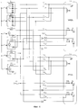
Структурная схема СК для включения и работы двигателя (в качестве примера выбран двигатель 1 и катод К1) приведена на фиг.2.The structural diagram of the SC for turning on and running the engine (as an example, engine 1 and cathode K 1 is selected) is shown in FIG. 2.
Известный способ реализуется следующим образом: выбирают двигатель и катод двигателя для включения, например двигатель 1.1 и катод К1; выбирают источники питания, используемые при данном включении, например 2.1 (ИПА1), 3.1 (НК1) и 4.1 (УП1); подключают используемые источники питания к выбранному двигателю и катоду контактами реле 5.1, 6.1, 9.1, 10.1; после этого включают источники питания контактами реле 15, 17, 19.The known method is implemented as follows: select the engine and the cathode of the engine to turn on, for example, the engine 1.1 and the cathode K 1 ; choose the power sources used for this inclusion, for example 2.1 (IPA1), 3.1 (NK1) and 4.1 (UP1); connect the used power sources to the selected motor and cathode by relay contacts 5.1, 6.1, 9.1, 10.1; then turn on the power supplies relay contacts 15, 17, 19.
После окончания работы двигателя выключают источники питания (размыкают контакты 15, 17, 19) и отключают их от двигателя (размыкают контакты реле 5.1, 6.1, 9.1, 10.1).After the engine is finished, turn off the power sources (open contacts 15, 17, 19) and disconnect them from the engine (open relay contacts 5.1, 6.1, 9.1, 10.1).
Известный способ позволяет выполнить требования гальванической развязки и обеспечить надежную работу СК в течение длительного срока активного существования за счет использования алгоритмов формирования требуемой структуры СК для включения двигателя, реализуемых с помощью коммутации выключенных источников питания, то есть используя бестоковый режим коммутации: за счет питания двигателей напряжением требуемого качества с низким уровнем излучаемых электромагнитных помех; а также за счет использования резервных элементов СК-двигателей, источников питания, электродов катода, поджига, накала.The known method allows to meet the requirements of galvanic isolation and to ensure reliable operation of the SC for a long period of active existence through the use of algorithms for the formation of the required structure of the SC to turn on the engine, implemented by switching off power supplies, that is, using the currentless switching mode: due to the supply of voltage to the motors required quality with a low level of emitted electromagnetic interference; and also through the use of backup elements of SK-engines, power supplies, cathode electrodes, ignition, glow.
Однако при известном способе питания и управления СК существует опасность повреждения электрических цепей, электронных и электротехнических схем в источниках питания в результате воздействия факторов электризации в условиях космического полета.However, with the known method of power supply and control of SC, there is a risk of damage to electrical circuits, electronic and electrical circuits in power sources as a result of exposure to electrification factors in space flight conditions.
А именно: во время геомагнитных возмущений плотность тока электронов с энергией в несколько тысяч электрон-вольт в пространстве вокруг КА может составлять 10-9A·см-2. Вследствие этого облучения керамический изолятор ЭРПД может накапливать заряд электронов, особенно при низких температурах. Конструкция двигателя не позволяет обеспечить эффективный сток накопленного керамикой заряда электронов. Этот заряд может вызвать высоковольтные пробои - электростатические разряды между керамическим изолятором и электродами двигателя. При этом высоковольтная динамическая помеха может пробить электрическую изоляцию имеющейся гальванической развязки и вывести из строя драйверы управления обмоток коммутаторов, а также проникнуть в электронные схемы источников питания и вывести их из строя.Namely: during geomagnetic disturbances, the current density of electrons with an energy of several thousand electron-volts in the space around the spacecraft can be 10 -9 A · cm -2 . As a result of this irradiation, the ceramic EPR insulator can accumulate an electron charge, especially at low temperatures. The design of the engine does not allow for an efficient drain of the electron charge accumulated by the ceramic. This charge can cause high voltage breakdowns - electrostatic discharges between the ceramic insulator and the motor electrodes. At the same time, high-voltage dynamic interference can break through the electrical isolation of the existing galvanic isolation and disable the control windings of the switch windings, as well as penetrate the electronic circuits of power supplies and disable them.
Экспериментально также установлена возможность возникновения статического потенциала на электрических цепях СК, связанного с непосредственным натеканием электронов из магнитосферной плазмы на проводящие элементы СК, гальванически развязанные от корпуса КА. Рост потенциала в дальнейшем может также привести к высоковольтным пробоям и повреждению элементов СК.The possibility of the appearance of a static potential on SC electrical circuits connected with the direct leakage of electrons from the magnetospheric plasma to the SC conductive elements galvanically isolated from the SC body was also experimentally established. Further potential growth can also lead to high-voltage breakdowns and damage to SC elements.
Цель заявляемого способа заключается в повышении надежности СК КА.The purpose of the proposed method is to increase the reliability of the SC SC.
Поставленная цель достигается тем, что в способе питания и управления системой коррекции космического аппарата выбирают один из ЭРПД, подлежащий включению, определяют необходимое время работы выбранного ЭРПД, выбирают используемые и неиспользуемые при данном включении электроды двигателей, источники питания, к выбранным электродам выбранного двигателя подключают с помощью контакторов используемые источники питания, затем включают и выключают указанные источники питания, обеспечивая запуск и работу ЭРПД в течение необходимого времени, по истечении которого выключают все источники питания, формируют высокоомную резистивную цепь стока электрического заряда с электродов ЭРПД на корпус КА, а также формируют два режима коммутации электрических цепей двигателя - "режим хранения", когда к электродам неработающих ЭРПД подключают основные и резервные источники питания со встроенными в эти источники емкостными фильтрами, и "режим защиты", когда во время работы СК электрические цепи выбранного ЭРПД оставляют подключенными к используемым (основным или резервным) источникам питания, электрические цепи всех остальных двигателей отключают от используемых источников питания и оставляют подключенными к неиспользуемым источникам питания, после чего используемые источники питания включаются и отключаются в соответствии с определенным алгоритмом.This goal is achieved by the fact that in the method of powering and controlling the correction system of the spacecraft, one of the ERPDs to be turned on is selected, the required operating time of the selected EPPD is determined, the motor electrodes used and unused during this turn-on are selected, the power sources are connected to the selected electrodes of the selected engine with using contactors, the used power sources, then turn on and turn off the specified power sources, ensuring the start and operation of the ERP for the required time nor, after which all power sources are turned off, form a high-resistance resistive circuit of the drain of electric charge from the ERP electrodes to the spacecraft’s body, and also form two modes of switching electric circuits of the engine - the “storage mode”, when the main and backup power sources are connected to the electrodes of inoperative ERP with capacitive filters built into these sources, and the “protection mode”, when during operation of the SC, the electric circuits of the selected ERP are left connected to the used (main or backup) sources power, the electrical circuits of all other engines are disconnected from the used power sources and left connected to unused power sources, after which the used power sources are turned on and off in accordance with a certain algorithm.
Сущность изобретения поясняется чертежами, где на фиг.3 изображена структурная схема СК в "режиме хранении", на фиг.4 приведена схема СК для включения и работы двигателя в "режиме защиты" (в качестве примера выбран двигатель 1 и катод К1).The invention is illustrated by drawings, where Fig. 3 shows a structural diagram of an SC in a "storage mode", Fig. 4 shows a diagram of an SC for turning on and operating the engine in a "protection mode" (as an example, engine 1 and cathode K 1 are selected).
Предлагаемый способ реализуется следующим образом:The proposed method is implemented as follows:
- в "режиме хранения" (фиг.3) замыкают все контакты, соединяющие источники питания 2.1, 2.2, 3.1, 3.2, 4.1, 4.2 с двигателями 1.1…1.n, контакты 15…20 разомкнуты, двигатели выключены;- in the "storage mode" (Fig.3) close all the contacts connecting the power sources 2.1, 2.2, 3.1, 3.2, 4.1, 4.2 with the engines 1.1 ... 1.n, the contacts 15 ... 20 are open, the motors are off;
- в "режиме защиты" (фиг.4) систему коррекции переводят из "режима хранения" следующим образом: выбирают используемый двигатель и катод двигателя, выбирают используемые источники питания, например двигатель 1.1, катод К1 источники 2.1, 3.1, 4.1; отключают от выбранного двигателя 1.1 неиспользуемые источники питания 2.2, размыкая контакты реле 7.1, 8.1; отключают от всех двигателей 1.n, кроме выбранного, используемые источники питания 2.1, размыкая контакты 5.n, 6.n. Таким образом, к выбранному двигателю 1.1 через контакты 5.1 и 6.1 подключены емкостные фильтры используемого источника питания 2.1, а к остальным двигателям 1.n через контакты 7.n и 8.n подключены емкостные фильтры неиспользуемого источника питания 2.2.- in the "protection mode" (figure 4), the correction system is transferred from the "storage mode" as follows: select the used engine and the cathode of the engine, select the power sources used, for example, engine 1.1, cathode K 1 sources 2.1, 3.1, 4.1; disconnect unused power sources 2.2 from the selected engine 1.1, opening the relay contacts 7.1, 8.1; disconnect from all engines 1.n, except for the selected one, the used power sources 2.1, opening contacts 5.n, 6.n. Thus, capacitive filters of the used power source 2.1 are connected to the selected motor 1.1 through contacts 5.1 and 6.1, and capacitive filters of an unused power source 2.2 are connected to the other engines 1.n through contacts 7.n and 8.n.
Сущность нового способа заключается в том, что формируют высокоомную резистивную цепь стока электрического заряда с электродов ЭРПД, а также используют встроенные в источники питания емкостные фильтры для защиты электрических цепей системы коррекции от высоковольтных динамических помех - пробоев, возникающих вследствие воздействия факторов электризации.The essence of the new method lies in the fact that they form a high-resistance resistive circuit of the drain of electric charge from the ERP electrodes, and also use capacitive filters built into the power sources to protect the electrical circuits of the correction system from high-voltage dynamic noise - breakdowns arising from the effects of electrification factors.
За счет подключения к электродам неработающих двигателей основных и резервных источников питания к ним оказываются подключенными встроенные в эти источники емкостные фильтры. Тем самым обеспечивается защита СК от динамических электростатических воздействий при разряде накопленного керамикой двигателя электрического заряда. Емкостные фильтры шунтируют цепи СК, замыкая цепи высоковольтных пробоев на корпус КА.Due to the connection of the main and backup power sources to the electrodes of the inoperative engines, capacitive filters built into these sources are connected to them. This ensures the protection of the SC from dynamic electrostatic influences during the discharge of an electric charge accumulated by the engine ceramic. Capacitive filters bypass the SC circuit, closing the circuit of high-voltage breakdowns on the spacecraft body.
Высокоомная резистивная цепь обеспечивает сток электрического заряда с электродов ЭРПД на корпус КА, тем самым снижая статический потенциал на электрических цепях СК и защищая их от высоковольтных пробоев.The high-resistance resistive circuit provides the drain of electric charge from the ERP electrodes to the spacecraft body, thereby reducing the static potential on the SC electric circuits and protecting them from high-voltage breakdowns.
Экспериментальная проверка при огневых испытаниях ЭРПД подтвердила устойчивую работу ЭРПД при сопротивлении резистивной цепи более 100 кОм.An experimental test during the fire tests of the ERPD confirmed the stable operation of the ERPD with a resistance of the resistive circuit of more than 100 kOhm.
В исходном состоянии СК электрические цепи всех двигателей подключены ко всем источникам питания, все источники выключены, емкостные фильтры всех источников питания шунтируют цепи высоковольтных пробоев. СК находится в "режиме хранения".In the initial state of the SC, the electric circuits of all engines are connected to all power sources, all sources are turned off, capacitive filters of all power sources bypass high-voltage breakdown circuits. SK is in "storage mode".
Во время работы СК электрические цепи выбранного двигателя оставляют подключенными к используемым источникам питания, электрические цепи всех остальных двигателей отключают от выбранных источников питания и оставляют подключенными к неиспользуемым источникам питания ("режим защиты").During operation of the SC, the electrical circuits of the selected engine are left connected to the used power sources, the electric circuits of all other motors are disconnected from the selected power sources and left connected to the unused power sources ("protection mode").
Затем выбранные источники питания включаются и отключаются в соответствии с определенным алгоритмом.Then, the selected power sources are turned on and off in accordance with a specific algorithm.
После окончания работы двигателя СК из "режима защиты" вновь переводится в "режим хранения".After the engine is finished, the SC from the "protection mode" is again transferred to the "storage mode".
В конечном состоянии СК все источники выключены, электрические цепи всех двигателей вновь подключены ко всем источникам питания, и емкостные фильтры всех источников питания шунтируют цепи высоковольтных пробоев.In the final state of the SC, all sources are turned off, the electric circuits of all motors are reconnected to all power sources, and capacitive filters of all power sources bypass high-voltage breakdown circuits.
Реализация указанного технического решения позволяет решить поставленную задачу повышением надежности системы коррекции космического аппарата.The implementation of the indicated technical solution allows us to solve the problem by increasing the reliability of the spacecraft correction system.
Claims (1)
Priority Applications (1)
| Application Number | Priority Date | Filing Date | Title |
|---|---|---|---|
| RU2013117105/11A RU2549318C2 (en) | 2013-04-15 | 2013-04-15 | Power supply and control method for spacecraft correction system |
Applications Claiming Priority (1)
| Application Number | Priority Date | Filing Date | Title |
|---|---|---|---|
| RU2013117105/11A RU2549318C2 (en) | 2013-04-15 | 2013-04-15 | Power supply and control method for spacecraft correction system |
Publications (2)
| Publication Number | Publication Date |
|---|---|
| RU2013117105A RU2013117105A (en) | 2014-10-20 |
| RU2549318C2 true RU2549318C2 (en) | 2015-04-27 |
Family
ID=53289927
Family Applications (1)
| Application Number | Title | Priority Date | Filing Date |
|---|---|---|---|
| RU2013117105/11A RU2549318C2 (en) | 2013-04-15 | 2013-04-15 | Power supply and control method for spacecraft correction system |
Country Status (1)
| Country | Link |
|---|---|
| RU (1) | RU2549318C2 (en) |
Cited By (1)
| Publication number | Priority date | Publication date | Assignee | Title |
|---|---|---|---|---|
| RU2624688C2 (en) * | 2015-12-15 | 2017-07-05 | Открытое акционерное общество "Ракетно-космическая корпорация "Энергия" имени С.П. Королева" | Device for mass calibration of working medium, gas at normal conditions, in electric propulsion system cylinder and method of its mass determination |
Citations (4)
| Publication number | Priority date | Publication date | Assignee | Title |
|---|---|---|---|---|
| US6029438A (en) * | 1997-10-15 | 2000-02-29 | Space Systems/Loral, Inc. | Drive circuit for electric propulsion thruster |
| US20020047622A1 (en) * | 1999-07-12 | 2002-04-25 | Hughes Electronics Corporation | Starter circuit for an ion engine |
| RU2220322C2 (en) * | 2001-10-08 | 2003-12-27 | Федеральное государственное унитарное предприятие "Научно-производственный центр "Полюс" | Method of and device for electric supply of electric plasma- jet rocker engine |
| RU2366123C1 (en) * | 2008-03-28 | 2009-08-27 | Федеральное государственное унитарное предприятие "Опытное конструкторское бюро "Факел" | Method of launch and power supply of electrojet plasma engine (versions) and device for its implementation (versions) |
-
2013
- 2013-04-15 RU RU2013117105/11A patent/RU2549318C2/en not_active IP Right Cessation
Patent Citations (4)
| Publication number | Priority date | Publication date | Assignee | Title |
|---|---|---|---|---|
| US6029438A (en) * | 1997-10-15 | 2000-02-29 | Space Systems/Loral, Inc. | Drive circuit for electric propulsion thruster |
| US20020047622A1 (en) * | 1999-07-12 | 2002-04-25 | Hughes Electronics Corporation | Starter circuit for an ion engine |
| RU2220322C2 (en) * | 2001-10-08 | 2003-12-27 | Федеральное государственное унитарное предприятие "Научно-производственный центр "Полюс" | Method of and device for electric supply of electric plasma- jet rocker engine |
| RU2366123C1 (en) * | 2008-03-28 | 2009-08-27 | Федеральное государственное унитарное предприятие "Опытное конструкторское бюро "Факел" | Method of launch and power supply of electrojet plasma engine (versions) and device for its implementation (versions) |
Cited By (1)
| Publication number | Priority date | Publication date | Assignee | Title |
|---|---|---|---|---|
| RU2624688C2 (en) * | 2015-12-15 | 2017-07-05 | Открытое акционерное общество "Ракетно-космическая корпорация "Энергия" имени С.П. Королева" | Device for mass calibration of working medium, gas at normal conditions, in electric propulsion system cylinder and method of its mass determination |
Also Published As
| Publication number | Publication date |
|---|---|
| RU2013117105A (en) | 2014-10-20 |
Similar Documents
| Publication | Publication Date | Title |
|---|---|---|
| US8742828B2 (en) | Disconnector switch for galvanic direct current interruption | |
| US9800171B2 (en) | Protection system for DC power transmission system, AC-DC converter, and method of interrupting DC power transmission system | |
| JPH03110737A (en) | Plasma switch having hollow cathode | |
| US11088689B2 (en) | Switching apparatus | |
| CN101636811A (en) | Reduce the method for particle contamination for ion implanters | |
| US20230257135A1 (en) | Micro-cathode arc propulsion system | |
| US20090284878A1 (en) | System and method for quickly discharging an ac relay | |
| CA2918522C (en) | High energy ignition generator notably for a gas turbine | |
| US10718319B2 (en) | Electric power supply system for a hall effect electric thruster | |
| RU2549318C2 (en) | Power supply and control method for spacecraft correction system | |
| CN103765545A (en) | Current limiter for high voltage power supply used with ion implantation system | |
| CN113285627B (en) | Pulse power supply system and neutron generator | |
| CN112260529B (en) | High-voltage direct-current input switching power supply and starting auxiliary source locking method | |
| JP6368928B2 (en) | Power supply for DC sputtering equipment | |
| JP2017059979A (en) | device | |
| RU2775741C1 (en) | Ignition and electronic discharge circuit for electric propulsion plant containing unheated dispenser cathode | |
| KR20160026058A (en) | Micro Pulse System Having Function for Restricting Current and Electrostatic Precipitator Using That Micro Pulse System | |
| RU2565646C1 (en) | Ionic engine | |
| Savvas et al. | Power Processing Unit For Micro Satellite Electric Propulsion System | |
| Kvasha et al. | Development of the INR DTL RF system crowbar operation | |
| US20220102944A1 (en) | Triggered vacuum gap that controllably sustains a vacuum arc through current zeros | |
| Aguglia | Design of a system of high voltage pulsed power converters for CERN's Linac4 H− ion source | |
| SU894813A1 (en) | Pulse gas-discharge device with two-side control | |
| RU2612308C1 (en) | Ion engine with device for protection against arc discharge in interelectrode gap of ion-optical system | |
| Savvas et al. | PPU for a small, low power and low cost EPS |
Legal Events
| Date | Code | Title | Description |
|---|---|---|---|
| MM4A | The patent is invalid due to non-payment of fees |
Effective date: 20180416 |