RU2549312C2 - Catheter device - Google Patents
Catheter device Download PDFInfo
- Publication number
- RU2549312C2 RU2549312C2 RU2012116204/14A RU2012116204A RU2549312C2 RU 2549312 C2 RU2549312 C2 RU 2549312C2 RU 2012116204/14 A RU2012116204/14 A RU 2012116204/14A RU 2012116204 A RU2012116204 A RU 2012116204A RU 2549312 C2 RU2549312 C2 RU 2549312C2
- Authority
- RU
- Russia
- Prior art keywords
- needle
- distal
- catheter device
- catheter
- branch
- Prior art date
Links
Images
Classifications
-
- A—HUMAN NECESSITIES
- A61—MEDICAL OR VETERINARY SCIENCE; HYGIENE
- A61M—DEVICES FOR INTRODUCING MEDIA INTO, OR ONTO, THE BODY; DEVICES FOR TRANSDUCING BODY MEDIA OR FOR TAKING MEDIA FROM THE BODY; DEVICES FOR PRODUCING OR ENDING SLEEP OR STUPOR
- A61M25/00—Catheters; Hollow probes
- A61M25/01—Introducing, guiding, advancing, emplacing or holding catheters
- A61M25/06—Body-piercing guide needles or the like
- A61M25/0612—Devices for protecting the needle; Devices to help insertion of the needle, e.g. wings or holders
- A61M25/0618—Devices for protecting the needle; Devices to help insertion of the needle, e.g. wings or holders having means for protecting only the distal tip of the needle, e.g. a needle guard
-
- A—HUMAN NECESSITIES
- A61—MEDICAL OR VETERINARY SCIENCE; HYGIENE
- A61M—DEVICES FOR INTRODUCING MEDIA INTO, OR ONTO, THE BODY; DEVICES FOR TRANSDUCING BODY MEDIA OR FOR TAKING MEDIA FROM THE BODY; DEVICES FOR PRODUCING OR ENDING SLEEP OR STUPOR
- A61M25/00—Catheters; Hollow probes
- A61M25/01—Introducing, guiding, advancing, emplacing or holding catheters
- A61M25/06—Body-piercing guide needles or the like
- A61M25/0612—Devices for protecting the needle; Devices to help insertion of the needle, e.g. wings or holders
- A61M25/0637—Butterfly or winged devices, e.g. for facilitating handling or for attachment to the skin
-
- A—HUMAN NECESSITIES
- A61—MEDICAL OR VETERINARY SCIENCE; HYGIENE
- A61M—DEVICES FOR INTRODUCING MEDIA INTO, OR ONTO, THE BODY; DEVICES FOR TRANSDUCING BODY MEDIA OR FOR TAKING MEDIA FROM THE BODY; DEVICES FOR PRODUCING OR ENDING SLEEP OR STUPOR
- A61M5/00—Devices for bringing media into the body in a subcutaneous, intra-vascular or intramuscular way; Accessories therefor, e.g. filling or cleaning devices, arm-rests
- A61M5/178—Syringes
- A61M5/31—Details
- A61M5/32—Needles; Details of needles pertaining to their connection with syringe or hub; Accessories for bringing the needle into, or holding the needle on, the body; Devices for protection of needles
- A61M5/3205—Apparatus for removing or disposing of used needles or syringes, e.g. containers; Means for protection against accidental injuries from used needles
- A61M5/321—Means for protection against accidental injuries by used needles
- A61M5/3243—Means for protection against accidental injuries by used needles being axially-extensible, e.g. protective sleeves coaxially slidable on the syringe barrel
- A61M5/3273—Means for protection against accidental injuries by used needles being axially-extensible, e.g. protective sleeves coaxially slidable on the syringe barrel freely sliding on needle shaft without connection to syringe or needle
Abstract
Description
Область техники, к которой относится изобретениеFIELD OF THE INVENTION
Изобретение относится к устройству медицинского катетера.The invention relates to a device for a medical catheter.
Уровень техникиState of the art
Катетеры являются широко известными устройствами. Как правило, предохранители для игл для катетеров выполнены таким образом, что они автоматически закрывают кончик иглы после ее выведения, например, из тела пациента. Предохранитель иглы, таким образом, служит для предотвращения случайного укола, например врача, кончиком иглы после ее удаления из медицинского устройства. Таким образом, иглу можно безопасно удалять после использования, без опасности передачи от пациента к врачу, возможно, особо опасных инфекционных и/или смертельных болезней.Catheters are widely known devices. Typically, catheter needle guards are designed so that they automatically close the tip of the needle after it has been removed, for example, from the patient’s body. The needle guard thus serves to prevent an accidental injection, for example by a doctor, with the tip of the needle after it has been removed from the medical device. Thus, the needle can be safely removed after use, without the risk of transmitting from the patient to the doctor, possibly especially dangerous infectious and / or fatal diseases.
Цель изобретения - разработка усовершенствованного устройства катетера.The purpose of the invention is the development of an improved catheter device.
Раскрытие изобретенияDisclosure of invention
Указанная цель достигается с помощью устройства катетера в соответствии с независимым пунктом формулы изобретения.This goal is achieved using a catheter device in accordance with an independent claim.
В общем, термин «проксимальный» относится к участку устройства или месту на устройстве, которое ближе всего, например, к врачу, использующему это устройство. Напротив, термин «дистальный» относится к участку устройства, который наиболее удален от врача, например дистальный участок иглы будет участком иглы, содержащим кончик иглы, который должен быть введен, например, в вену пациента.In general, the term “proximal” refers to a portion of a device or a location on a device that is closest, for example, to a doctor using this device. On the contrary, the term "distal" refers to the portion of the device that is farthest from the doctor, for example, the distal portion of the needle will be the portion of the needle containing the tip of the needle, which must be inserted, for example, into a patient's vein.
Устройство катетера по изобретению содержит катетерную трубку, разъем катетера и иглу, имеющую стержень иглы, кончик иглы и разъем иглы, причем стержень иглы имеет дистальный участок и проксимальный участок, где по меньшей мере проксимальный участок имеет главный внешний контур. Устройство катетера также содержит предохранитель для иглы, имеющий изготовленную из первого материала основную часть с проходным каналом для иглы, проходящим в осевом направлении от проксимальной стороны основной части через основную часть к дистальной стороне основной части, таким образом, чтобы игла, имеющая главный внешний контур, могла быть подвижно расположена в канале для иглы. Предохранитель иглы также имеет первый и второй отводы, продолжающиеся главным образом в осевом направлении от дистальной стороны основной части, причем первый отвод имеет дистальный участок и проксимальный участок. На дистальном участке первого отвода поперечно расположена дистальная стенка.The catheter device of the invention comprises a catheter tube, a catheter connector and a needle having a needle shaft, a needle tip and a needle connector, the needle shaft having a distal portion and a proximal portion, where at least the proximal portion has a main external contour. The catheter device also contains a needle guard, having a main part made of the first material with a passage for the needle extending axially from the proximal side of the main part through the main part to the distal side of the main part, so that the needle having a main outer contour, could be movably located in the channel for the needle. The needle guard also has first and second branches, extending mainly in the axial direction from the distal side of the main part, the first branch having a distal section and a proximal section. In the distal portion of the first branch, a distal wall is laterally arranged.
Устройство катетера отличается наличием запорного элемента, выполненного из второго материала, отличающегося от первого материала. Запорный элемент расположен в указанном предохранителе иглы и имеет сквозное отверстие с профилем, который адаптирован к главному внешнему контуру стержня иглы. В случае, например, круговых поперечных сечений, диаметр сквозного отверстия может быть немного больше, чем главный наружный диаметр иглы.The catheter device is characterized by the presence of a locking element made of a second material different from the first material. The locking element is located in the specified needle guard and has a through hole with a profile that is adapted to the main external contour of the needle shaft. In the case of, for example, circular cross-sections, the diameter of the through hole may be slightly larger than the main outer diameter of the needle.
Для обеспечения свободного движения иглы относительно предохранителя иглы, когда игла выведена из трубки катетера, запорный элемент располагают таким образом, чтобы его сквозное отверстие было по существу выровненным с каналом для иглы предохранителя иглы.To ensure free movement of the needle relative to the needle guard, when the needle is withdrawn from the catheter tube, the closure member is positioned so that its through hole is substantially aligned with the needle guard channel for the needle.
Запорный элемент может представлять собой круглый диск, кольцо или шайбу. Однако он не обязательно должен быть круглым и может иметь какую-либо другую геометрическую форму: прямоугольную, квадратную или треугольную форму.The locking element may be a round disc, ring or washer. However, it does not have to be round and may have some other geometric shape: rectangular, square or triangular.
В соответствии с изобретением, второй материал должен быть тверже и/или жестче, чем первый материал. Например, первый материал может быть пластмассой, а второй материал может состоять из металла, керамики или резины или любого другого типа материала, который обладает жесткостью и не так легко деформируется, как первый материал.In accordance with the invention, the second material must be harder and / or stiffer than the first material. For example, the first material may be plastic, and the second material may consist of metal, ceramic or rubber, or any other type of material that is rigid and not as easily deformed as the first material.
Стержень иглы также имеет расширение между дистальным участком и проксимальным участком. Расширение имеет внешний профиль, параметр которого больше, чем максимальный параметр профиля сквозного отверстия канала для иглы и/или запорного элемента. В предпочтительном варианте расширение выполняют опрессовкой стержня иглы. Тем не менее возможны другие способы формирования расширения, такие как нанесение дополнительного материала на стержень иглы, например, с помощью пайки, сварки или склеивания и т.д.The needle shaft also has an extension between the distal portion and the proximal portion. The extension has an external profile, the parameter of which is greater than the maximum profile parameter of the through hole of the channel for the needle and / or locking element. In a preferred embodiment, the expansion is performed by crimping the needle shaft. However, other methods of forming the expansion are possible, such as applying additional material to the needle shaft, for example, by soldering, welding or gluing, etc.
Внутренний профиль иглы может либо быть уменьшен в области расширения, например, если расширение формируется опрессовкой, либо он может быть постоянным на протяжении всей длины иглы, например, если расширение образуется путем нанесения дополнительного материала на стержень иглы.The inner profile of the needle can either be reduced in the area of expansion, for example, if the expansion is formed by crimping, or it can be constant throughout the length of the needle, for example, if the expansion is formed by applying additional material to the needle shaft.
Перед использованием устройства катетера предохранитель иглы располагают в разъеме катетера около проксимального конца стержня иглы. В этом положении игла полностью проходит через предохранитель иглы, тем самым отклоняя первый отвод предохранителя иглы наружу, то есть под углом к осевому направлению, таким образом, что дистальную стенку первого отвода поддерживает стержень иглы. После введения катетера пациенту иглу извлекают из катетерной трубки, и стержень иглы движется через предохранитель иглы, в то время как предохранитель иглы удерживается разъемом катетера. Как только кончик иглы проходит поперечную дистальную стенку иглы, то есть стержень иглы больше не поддерживает дистальную стенку, сила восстановления обеспечивает возвращение первого отвода предохранителя иглы в положение, выровненное с осевым направлением иглы, так что кончик иглы блокирован дистальной стенкой предохранителя иглы, то есть предотвращается осевой выход кончика иглы за пределы предохранителя иглы.Before using the catheter device, the needle fuse is located in the catheter connector near the proximal end of the needle shaft. In this position, the needle completely passes through the needle guard, thereby deflecting the first outlet of the needle guard to the outside, i.e. at an angle to the axial direction, so that the needle shaft supports the distal wall of the first outlet. After the catheter is inserted into the patient, the needle is removed from the catheter tube, and the needle shaft moves through the needle guard, while the needle guard is held by the catheter connector. As soon as the tip of the needle passes through the transverse distal wall of the needle, that is, the needle shaft no longer supports the distal wall, the recovery force ensures that the first retraction of the needle guard returns to a position aligned with the axial direction of the needle, so that the tip of the needle is blocked by the distal wall of the needle guard, i.e. is prevented axial exit of the needle tip beyond the needle fuse.
Как только дистальная стенка блокирует кончик иглы, расширение стержня иглы вступает в контакт с запорным элементом, чтобы предотвратить удаление предохранителя иглы со стержня иглы. То обстоятельство, что запорный элемент изготовлен из второго материала, который тверже и менее легко деформируется, чем первый материал основной части, приводит к тому, что предохранитель иглы закреплен более эффективно на стержне иглы. Поэтому его можно сохранить на игле, даже если применяют чрезмерную внешнюю силу, когда иглу тянут, так как расширение нельзя извлечь через основную часть предохранителя иглы благодаря запорному элементу. Следовательно, маловероятно, чтобы предохранитель иглы был удален с кончика иглы случайно, и в результате предохранитель иглы обеспечивает лучшую защиту от случайного укола и тем самым повышает безопасность для человека при обращении с устройством катетера.As soon as the distal wall blocks the tip of the needle, the expansion of the needle shaft comes into contact with the locking element to prevent the removal of the needle guard from the needle shaft. The fact that the locking element is made of a second material that is harder and less easily deformed than the first material of the main part leads to the fact that the needle guard is attached more efficiently to the needle shaft. Therefore, it can be stored on the needle even if excessive external force is applied when the needle is pulled, since the expansion cannot be removed through the main part of the needle guard due to the locking element. Therefore, it is unlikely that the needle guard was accidentally removed from the tip of the needle, and as a result, the needle guard provides better protection against accidental injection and thereby increases the safety for humans when handling the catheter device.
В следующем варианте выполнения устройства катетера первый и второй отводы предохранителя иглы окружены натяжным элементом. В отклоненном состоянии первого отвода натяжной элемент расширяется против силы восстановления натяжного элемента. После того как стержень иглы больше не поддерживает дистальную стенку, натяжной элемент способствует изменению положения первого отвода обратно в осевое выравнивание с осевым направлением. Это изменение положения необходимо, чтобы дистальная стенка могла блокировать кончик иглы от осевого выскальзывания из предохранителя иглы. Кроме того, натяжной элемент помогает замкнуть пространство между первым и вторым отводами и таким образом помогает предотвратить выхождение кончика иглы за пределы предохранителя иглы в боковых направлениях. Другими словами, натяжной элемент вносит дополнительный вклад в защитное действие предохранителя иглы.In a further embodiment of the catheter device, the first and second taps of the needle guard are surrounded by a tension element. In the deflected state of the first outlet, the tension element expands against the recovery force of the tension element. After the needle shaft no longer supports the distal wall, the tension element helps to reposition the first outlet back to axial alignment with the axial direction. This change of position is necessary so that the distal wall can block the tip of the needle from axial slipping out of the needle guard. In addition, the tension element helps close the space between the first and second taps and thus helps prevent the tip of the needle from extending beyond the needle guard in the lateral directions. In other words, the tension element makes an additional contribution to the protective action of the needle guard.
В следующем варианте выполнения устройства катетера в проксимальном участке первого отвода предохранителя иглы выполнено углубление. Это углубление увеличивает изгибаемость первого отвода в той области, где оно расположено, и таким образом уменьшает силу восстановления, действующую на дистальную стенку, в то время как ее поддерживает стержень иглы. Это позволяет стержню иглы легче перемещаться относительно дистальной стенки, поскольку уменьшается сила трения, действующая на стержень иглы.In a further embodiment of the catheter device, a recess is made in the proximal portion of the first tap of the needle guard. This recess increases the bendability of the first branch in the area where it is located, and thus reduces the recovery force acting on the distal wall, while it is supported by the needle shaft. This allows the needle shaft to more easily move relative to the distal wall, since the friction force acting on the needle shaft is reduced.
В следующем варианте выполнения устройства катетера в боку дистальной стенки выполнен паз, идущий главным образом в осевом направлении. Паз действует в качестве направляющего паза для стержня иглы и способствует осевому перемещению стержня иглы относительно предохранителя иглы. Кроме того, предотвращается выскальзывание стержня иглы в боковых направлениях от дистальной стенки. Подобное боковое перемещение может значительно увеличивать силу, необходимую для перемещения стержня иглы относительно предохранителя иглы, что препятствовало бы правильному функционированию предохранителя иглы.In a further embodiment of the catheter device, a groove is made in the side of the distal wall, extending mainly in the axial direction. The groove acts as a guide groove for the needle shaft and facilitates axial movement of the needle shaft relative to the needle guard. In addition, slipping of the needle shaft in the lateral directions from the distal wall is prevented. Such lateral movement can significantly increase the force required to move the needle shaft relative to the needle guard, which would interfere with the proper functioning of the needle guard.
Дальнейшие преимущества изобретения и предпочтительных устройств для реализации изобретения изложены в зависимых пунктах формулы изобретения и описаны с использованием сопроводительных чертежей.Further advantages of the invention and preferred devices for carrying out the invention are set forth in the dependent claims and are described using the accompanying drawings.
Краткое описание чертежейBrief Description of the Drawings
Настоящее изобретение будет далее объяснено более подробно со ссылкой на предпочтительные варианты воплощения и сопроводительные чертежи, на которых показаны:The present invention will be further explained in more detail with reference to preferred embodiments and accompanying drawings, in which:
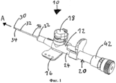
Фиг.1 - устройство катетера по изобретению;Figure 1 - catheter device according to the invention;
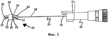
Фиг.2 - игла, разъем иглы и предохранитель иглы, удаленные из устройства катетера, изображенного на Фиг.1;Figure 2 - needle, needle connector and needle guard removed from the catheter device shown in Figure 1;
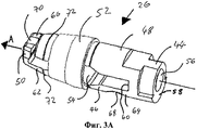
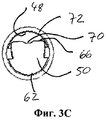
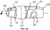
Фиг.3A-3D - предохранитель иглы, изображенный на Фиг.2;Figa-3D - needle guard, shown in Fig.2;
Фиг.4A-4C - дополнительные изображения предохранителя иглы, изображенного на Фиг.2, без натяжного элемента;Figa-4C - additional images of the needle guard shown in Fig.2, without a tension element;
Фиг.5A-5B - представленные в разрезе чертежи предохранителя иглы, изображенного на Фиг.4; и5A-5B are cross-sectional drawings of a needle fuse of FIG. 4; and
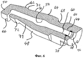
Фиг.6 - вид в перспективе предохранителя иглы, изображенного на Фиг.4, в разрезе.Fig.6 is a perspective view of the needle guard depicted in Fig.4, in section.
Осуществление изобретенияThe implementation of the invention
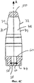
На Фиг.1 показано устройство 10 катетера в соответствии с изобретением. Устройство 10 катетера включает в себя разъем 12 катетера, катетерную трубку 14, крылья 16, порт 18 и иглу 20. Разъем 12 катетера имеет дистальный конец 22 и проксимальный конец 24, катетерная трубка 14 прилегает к дистальному концу 22 разъема 12 катетера.1 shows a
Игла 20, показанная на Фиг.2, имеет стержень иглы, кончик 30 иглы на дистальном участке 34 стержня иглы и разъем 42 иглы, присоединенный к проксимальному участку 36 стержня 28 иглы. И дистальный участок 34, и проксимальный участок 36 в общем случае имеют одинаковый внешний профиль. В настоящем варианте воплощения изобретения дистальный и проксимальный участки 34, 36 имеют круглые в разрезе сечения, с по существу идентичными внешними диаметрами.The
Расширение 32 иглы 20 выполнено между дистальным участком 34 и проксимальным участком 36 стержня 28 иглы. Расширение 32 имеет максимальный размер в направлении, поперечном стержню иглы, который больше, чем внешний диаметр дистального и проксимального участков 34, 36. Расширение 32 можно выполнить, например, опрессовкой стержня 28 иглы.The
Перед использованием устройства 10 катетера игла 20 размещена в разъеме 12 катетера и трубке 14 катетера, так что стержень иглы проходит через всю длину трубки 14 катетера.Before using the
Предохранитель 26 иглы подвижно расположен на стержне 28 иглы и перед использованием устройства 10 катетера удерживается разъемом 12 катетера. Предохранитель 26 иглы имеет основную часть 44, первый отвод 46, второй отвод 48 и дистальную стенку 50. Дистальная стенка 50 расположена на дистальном конце первого отвода 46 и проходит в направлении, поперечном осевому направлению. Натяжной элемент 52, например резиновая лента или тому подобное, окружает первый и второй отводы 46, 48.The
После извлечения иглы 20 из катетерной трубки 14 и разъема 12 катетера стержень 28 иглы перемещается относительно предохранителя 26 иглы до тех пор, пока кончик 30 иглы не окажется в предохранителе 26 иглы. Как только кончик 30 иглы оказывается в предохранителе 26 иглы, расширение 32 стержня 28 иглы вступает в контакт с основной частью 44 предохранителя 26 иглы таким образом, что предохранитель 26 иглы можно вытащить из разъема 12 катетера вместе с иглой 20. Осевое перемещение иглы 20 по отношению к предохранителю 26 иглы теперь ограничено, так как дистальная стенка 50 блокирует кончик 30 иглы, а зацепление между расширением 32 и основной частью 44 предохранителя 26 иглы препятствует удалению кончика иглы через основную часть 44, то есть кончик 30 иглы безопасно окружен предохранителем 26 иглы, как показано на Фиг.2.After removing the
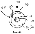
На Фиг.3-6 более подробно показан предохранитель 26 иглы.Figure 3-6 shows in more detail the
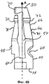
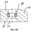
Как видно на Фиг.3A, основная часть 44 имеет канал 56 для иглы, проходящий в осевом направлении А от проксимальной стороны 58 основной части 44 через основную часть 44 к дистальной стороне 60 основной части 44. Канал 56 для иглы сконфигурирован таким образом, чтобы вмещать проксимальный участок 36 стержня 28 иглы и разрешать движение стержня 28 иглы относительно предохранителя 26 иглы. По этой причине диаметр канала 56 для иглы немного больше, чем внешний диаметр проксимального участка 36 стержня 28 иглы.3A, the
Первый и второй отводы 46, 48 предохранителя 26 иглы располагают, как правило, в осевом направлении А от дистальной стороны 60 основной части 44, то есть по существу параллельно стержню 28 иглы. Первый отвод 46 имеет дистальный участок 62 и проксимальный участок 64, с углублением 68, выполненном на проксимальном участке 64 первого отвода 46. Углубление 68 выполняют для облегчения отклонения первого отвода 46 и снижения возвратной силы, действующей на первый отвод 46, когда первый отвод 46 отклонен от оси.The first and second taps 46, 48 of the
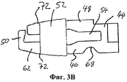
Внешние поверхности 71 дистальных участков 62 первого и второго отводов 46, 48 сужаются от основной части 44 к дистальной стенке 50 (см. Фиг.4B-4C). На своих дистальных концах конические поверхности 71 ограничены выступами или плечиками 72, образованными на первом и втором отводах 46, 48. Плечики 72 и конические поверхности 71 определяют осевое положение натяжного элемента 52 и, в частности, предотвращают осевое соскальзывание натяжного элемента 52 с первого и второго отводов 46, 48.The
Поперечная дистальная стенка 50 имеет сторону 66 на своем свободном конце, в котором выполнен паз 70. Паз 70 проходит в направлении, по существу параллельном осевому направлению А, и его используют для направления стержня 28 иглы.The transverse
Как упоминалось выше, перед использованием устройства 10 катетера игла 20 проходит через трубку 14 катетера, а предохранитель 26 иглы расположен в разъеме 12 катетера. В этом положении дистальная стенка 50 предохранителя 26 иглы контактирует с иглой 20, со стержнем 28 иглы, направляемым в пазу 70 на стороне 66 дистальной стенки 50. Стержень 28 иглы таким образом поддерживает дистальную стенку 50, с помощью которой первый отвод 46 предохранителя 26 иглы отклоняется наружу, то есть в сторону от иглы 20, против восстановительной силы натяжного элемента 52.As mentioned above, before using the
Для удержания предохранителя 26 иглы в разъеме 12 катетера, когда иглу 20 извлекают из трубки 14 катетера, плечики 72, выполненные на первом отводе 46 и втором отводе 48 предохранителя 26 иглы, взаимодействуют с углублениями или выступами или их комбинациями (не показано), выполненными в разъеме 12 катетера. Выступы могут образовывать кольцо вдоль всей внутренней периферии разъема 12 катетера или они могут образовывать одно или более кольцевых сегментов, проходящих вдоль только соответствующей части внутренней окружности разъема 12 катетера. Аналогичным образом, углубления могут образовывать кольцо, проходящее вдоль всей внутренней периферии разъема 12 катетера, или они могут образовывать один или несколько сегментов, проходящих вдоль только соответствующей части внутренней окружности разъема 12 катетера.To hold the
После того как иглу 20 извлекают так, что кончик 30 иглы пройдет дистальную стенку 50 и окажется между первым и вторым отводами, стержень иглы 28 больше не поддерживает дистальную стенку 50. Это приводит к тому, что первый отвод 46 сам вернет себя в осевое положение, выровненное с иглой 20, за счет восстановительной силы, действующей на первый отвод 46 в изогнутом состоянии. Повторному выравниванию первого отвода 46 способствует использование натяжного элемента 52. Повторное выравнивание первого отвода 46 приводит к тому, что плечики 72 разъединяются с углублениями или выступами в разъеме 12 катетера, позволяя удалить предохранитель 26 иглы, покрывающий кончик 30 иглы, из разъема 12 катетера вместе с иглой 20, с защищенным кончиком иглы 30, расположенным в пространстве 54, которое ограничено основной частью 44, первым и вторым отводами 46, 48, дистальной стенкой 50 и натяжным элементом 52.After the
В предохранителе иглы 26 имеется запорный элемент 38. Согласно данному варианту запорный элемент 38 расположен в основной части 44 предохранителя 26 иглы (см. Фиг.4A и Фиг.4C). Однако следует понимать, что запорный элемент 38 не нужно располагать в самой основной части 44, его можно разместить на дистальной стороне 60 этого основания, между первым отводом 46 и вторым отводом 48. Положение запорного элемента 38 в основной части 44 можно выбирать свободно.The
Кроме того, запорный элемент 38 не нужно располагать перпендикулярно продольной оси А, его можно расположить под углом к продольной оси А, например, таким образом, чтобы сквозное отверстие запорного элемента 38 совмещалось с пазом 70 дистальной стенки 50, когда первый отвод 46 отклонен. Угол размещения запорного элемента 38 внутри основной части 44 по отношению к продольной оси А можно выбрать в диапазоне от 55° до 85° к продольной оси А, предпочтительно под углом в диапазоне от 60° до 80° к продольной оси А. Размещение запорного элемента под углом к продольной оси А позволяет сократить силу трения, действующую на иглу во время извлечения иглы.In addition, the locking
Запорный элемент 38 имеет дискообразную форму, наподобие шайбы, и его изготавливают из материала, отличающегося от материала основной части 44, в частности материала с большей твердостью и/или жесткостью, чем материал основной части 44. Желательно изготовление запорного элемента 38 из металла или керамики, но его можно сделать из любого другого материала, который обладает жесткостью и трудно сгибается.The locking
Основная часть 44 и первый и второй отводы 46, 48 предохранителя 26 иглы можно изготовить из пластмассы, например, процессом формования, когда запорный элемент 38 размещен в изложнице до процесса формования. Материал основной части 44 и первого и второго отводов 46, 48 отличается от материала запорного элемента 38.The
Запорный элемент 38 имеет сквозное отверстие 74 с круглым сечением, диаметр которого немного больше, чем главный диаметр проксимального участка 36 стержня 28 иглы, с тем чтобы допустить движение проксимального участка 36 стержня 28 иглы относительно запорного элемента 38. В то же время диаметр сквозного отверстия 74 не только меньше, чем канал 56 для иглы, но также меньше, чем максимальный размер расширения 32 стержня 28 иглы, для того чтобы не допустить прохождения расширения 32 через сквозное отверстие 74.The locking
Даже в случае применения избыточной внешней силы к игле 20 и/или предохранителю 26 иглы, запорный элемент 38 препятствует протягиванию расширения 32 стержня иглы через проходной канал 56 для иглы в основной части 44. Таким образом, запорный элемент 38 улучшает безопасность предохранителя 26 иглы.Even if excessive external force is applied to the
Список позиционных обозначенийList of Keys
10 катетер10 catheter
12 разъем катетера12 catheter connector
14 трубка катетера14 catheter tube
16 крылья16 wings
18 порт18 port
20 игла20 needle
22 дистальный конец22 distal end
24 проксимальный конец24 proximal end
26 предохранитель иглы26 needle fuse
28 стержень иглы28 needle shaft
30 кончик иглы30 needle tip
32 расширение32 extension
34 дистальный участок34 distal section
36 проксимальный участок36 proximal section
38 запорный элемент38 locking element
42 разъем иглы42 needle connector
44 основная часть44 main part
46 первый отвод46 first challenge
48 второй отвод48 second tap
50 дистальная стенка50 distal wall
52 натяжной элемент52 tension element
54 пространство54 space
56 канал для иглы56 channel for needles
58 проксимальная сторона58 proximal side
60 дистальная сторона60 distal side
62 дистальный участок62 distal section
64 проксимальный участок64 proximal section
66 сторона66 side
68 углубление68 recess
70 паз70 groove
71 внешняя поверхность71 outer surface
72 плечо72 shoulder
74 сквозное отверстие74 through hole
A осевое направлениеA axial direction
B детализированная областьB detailed area
Claims (10)
основную часть (44), изготовленную из первого материала и имеющую канал (56)для иглы, проходящий в осевом направлении (А) от проксимальной стороны (58) указанной основной части (44) через указанную основную часть (44) к дистальной стороне (60) указанной основной части (44) для подвижного вмещения указанного стержня (28) иглы, причем максимальный размер сечения канала (56) для иглы меньше, чем максимальный размер указанного расширения (32) иглы;
первый и второй отводы (46, 48), проходящие по существу в осевом направлении (А) от указанной дистальной стороны (60) указанной основной части (44), где указанный первый отвод (46) имеет дистальный участок (62) и проксимальный участок (64), и
дистальную стенку (50), расположенную поперечно на указанном дистальном участке (62) указанного первого отвода (46);
отличающееся тем, что в указанном предохранителе (26) иглы расположен жесткий запорный элемент (38), изготовленный из второго материала, отличного от указанного первого материала, и имеющий дискообразную форму со сквозным отверстием (74) постоянного диаметра, размер которого больше основного диаметра проксимального участка (36) стержня (28) иглы и меньше максимального размера указанного расширения (32).1. A catheter device (40) comprising a catheter tube (14), a catheter connector (12), a needle (20) having a needle shaft (28), a needle tip (30) and a needle connector (42), the shaft (28) the needle has a distal section (34) and a proximal section (36), where at least the proximal section (36) has a main external contour, and on the needle shaft (28) between the specified distal section (34) and the specified proximal section (36) extension (32); and a needle fuse (26) having:
a main body (44) made of the first material and having a needle channel (56) extending in the axial direction (A) from the proximal side (58) of the main body (44) through the main body (44) to the distal side (60 ) the specified main part (44) for movably accommodating the specified rod (28) of the needle, and the maximum size of the cross section of the channel (56) for the needle is less than the maximum size of the specified extension (32) of the needle;
the first and second branches (46, 48) extending essentially in the axial direction (A) from the specified distal side (60) of the indicated main part (44), where the specified first branch (46) has a distal section (62) and a proximal section ( 64), and
a distal wall (50) transversely located on said distal portion (62) of said first branch (46);
characterized in that in said needle guard (26) there is a rigid locking element (38) made of a second material different from said first material and having a disk-like shape with a through hole (74) of constant diameter, the size of which is larger than the main diameter of the proximal section (36) the rod (28) of the needle and less than the maximum size of the specified extension (32).
Applications Claiming Priority (3)
| Application Number | Priority Date | Filing Date | Title |
|---|---|---|---|
| IN1965DE2009 | 2009-09-22 | ||
| IN1965/DEL/2009 | 2009-09-22 | ||
| PCT/IB2010/052034 WO2011036574A1 (en) | 2009-09-22 | 2010-05-07 | An improved needle tip guard |
Publications (2)
| Publication Number | Publication Date |
|---|---|
| RU2012116204A RU2012116204A (en) | 2013-10-27 |
| RU2549312C2 true RU2549312C2 (en) | 2015-04-27 |
Family
ID=42732128
Family Applications (1)
| Application Number | Title | Priority Date | Filing Date |
|---|---|---|---|
| RU2012116204/14A RU2549312C2 (en) | 2009-09-22 | 2010-05-07 | Catheter device |
Country Status (13)
| Country | Link |
|---|---|
| US (1) | US9289579B2 (en) |
| EP (5) | EP2735330B1 (en) |
| JP (1) | JP5719371B2 (en) |
| CN (1) | CN102639180B (en) |
| AU (1) | AU2010299500B2 (en) |
| BR (1) | BR112012006476A2 (en) |
| ES (3) | ES2747233T3 (en) |
| MX (1) | MX2012003356A (en) |
| MY (1) | MY157127A (en) |
| RU (1) | RU2549312C2 (en) |
| UA (1) | UA107363C2 (en) |
| WO (1) | WO2011036574A1 (en) |
| ZA (1) | ZA201202241B (en) |
Families Citing this family (40)
| Publication number | Priority date | Publication date | Assignee | Title |
|---|---|---|---|---|
| US9162037B2 (en) | 2005-07-06 | 2015-10-20 | Vascular Pathways, Inc. | Intravenous catheter insertion device and method of use |
| JP4994775B2 (en) | 2006-10-12 | 2012-08-08 | 日本コヴィディエン株式会社 | Needle point protector |
| ATE489989T1 (en) | 2007-05-07 | 2010-12-15 | Vascular Pathways Inc | INTRODUCTION OF AN INTRAVENOUS CATHETER AND BLOOD COLLECTION DEVICE AND METHOD OF USE |
| DE102009020061A1 (en) | 2009-05-06 | 2010-11-11 | B. Braun Melsungen Ag | Needle protection device for a medical hollow needle |
| US11925779B2 (en) | 2010-05-14 | 2024-03-12 | C. R. Bard, Inc. | Catheter insertion device including top-mounted advancement components |
| US9950139B2 (en) | 2010-05-14 | 2018-04-24 | C. R. Bard, Inc. | Catheter placement device including guidewire and catheter control elements |
| US8932258B2 (en) | 2010-05-14 | 2015-01-13 | C. R. Bard, Inc. | Catheter placement device and method |
| US9872971B2 (en) | 2010-05-14 | 2018-01-23 | C. R. Bard, Inc. | Guidewire extension system for a catheter placement device |
| US10384039B2 (en) | 2010-05-14 | 2019-08-20 | C. R. Bard, Inc. | Catheter insertion device including top-mounted advancement components |
| US8257322B2 (en) | 2010-06-02 | 2012-09-04 | Smiths Medical Asd, Inc. | Tip protector for a safety catheter |
| CN106943647B (en) * | 2010-08-05 | 2020-09-04 | B·布朗·梅尔松根有限公司 | Needle safety device and assembly |
| US9302077B2 (en) | 2010-09-23 | 2016-04-05 | Vigmed Ab | Needle tip shielding device |
| US8690833B2 (en) | 2011-01-31 | 2014-04-08 | Vascular Pathways, Inc. | Intravenous catheter and insertion device with reduced blood spatter |
| CN103379937B (en) | 2011-02-25 | 2016-09-07 | C·R·巴德股份有限公司 | Medical component insertion device including retractible pin |
| US8486024B2 (en) | 2011-04-27 | 2013-07-16 | Covidien Lp | Safety IV catheter assemblies |
| WO2012150522A1 (en) * | 2011-05-03 | 2012-11-08 | Poly Medicure Limited | An improved needle tip guard |
| USD903101S1 (en) | 2011-05-13 | 2020-11-24 | C. R. Bard, Inc. | Catheter |
| US9440053B2 (en) | 2011-07-26 | 2016-09-13 | Poly Medicure Limited | Needle tip protector assembly for safety IV catheter assembly |
| EP2736577B1 (en) * | 2011-07-26 | 2022-11-30 | Poly Medicure Limited | Needle tip protector assembly for safety iv catheter assembly |
| US8715250B2 (en) | 2011-09-26 | 2014-05-06 | Covidien Lp | Safety catheter and needle assembly |
| US8834422B2 (en) | 2011-10-14 | 2014-09-16 | Covidien Lp | Vascular access assembly and safety device |
| EP2974764B1 (en) | 2011-11-08 | 2016-10-19 | Poly Medicure Limited | Intravenous catheter apparatus |
| IN2012DE00486A (en) | 2012-02-21 | 2015-06-05 | Poly Medicure Ltd | |
| RU2632530C2 (en) * | 2012-06-19 | 2017-10-05 | Поли Медикьюэ Лимитед | Needle cap |
| CN108607150B (en) | 2013-01-30 | 2021-01-12 | 血管通路股份有限公司 | Systems and methods for venipuncture and catheter placement |
| JP6093256B2 (en) | 2013-07-05 | 2017-03-08 | サクラ精機株式会社 | Tissue piece processing method and tissue piece processing apparatus |
| IN2013DE03088A (en) * | 2013-10-17 | 2015-04-24 | Poly Medicure Ltd | |
| AU2014369757B2 (en) * | 2013-12-20 | 2019-06-06 | B. Braun Melsungen Ag | Safety needle assemblies and related methods |
| US9555221B2 (en) | 2014-04-10 | 2017-01-31 | Smiths Medical Asd, Inc. | Constant force hold tip protector for a safety catheter |
| WO2016037127A1 (en) | 2014-09-05 | 2016-03-10 | C.R. Bard, Inc. | Catheter insertion device including retractable needle |
| USD903100S1 (en) | 2015-05-01 | 2020-11-24 | C. R. Bard, Inc. | Catheter placement device |
| CN107708769B (en) | 2015-05-15 | 2021-07-27 | C·R·巴德股份有限公司 | Catheter placement device including extendable needle safety feature |
| SG11201901968TA (en) | 2016-09-12 | 2019-04-29 | Bard Inc C R | Blood control for a catheter insertion device |
| CN106618748B (en) * | 2016-12-28 | 2019-02-05 | 李灏来 | One kind being mostly used anti-needle and stabs instrument and its application method |
| BR112019018016B1 (en) | 2017-03-01 | 2023-10-24 | C.R. Bard, Inc. | CATHETER INSERTION TOOL |
| BR112020017215A2 (en) | 2018-03-07 | 2020-12-22 | Bard Access Systems, Inc. | GUIDELINE ADVANCE SYSTEMS AND REVERSE BLOOD SQUEEZE FOR A MEDICAL DEVICE INSERT SYSTEM |
| USD921884S1 (en) | 2018-07-27 | 2021-06-08 | Bard Access Systems, Inc. | Catheter insertion device |
| CN112386778A (en) | 2019-08-19 | 2021-02-23 | 贝克顿·迪金森公司 | Midline catheter placement device |
| RU2734973C1 (en) | 2020-05-04 | 2020-10-26 | Общество С Ограниченной Ответственностью "Аквафор" (Ооо "Аквафор") | Filtering module |
| BR112023016553A2 (en) | 2021-03-02 | 2023-09-26 | Greiner Bio One Gmbh | Method for manufacturing a thermoplastic unit |
Citations (3)
| Publication number | Priority date | Publication date | Assignee | Title |
|---|---|---|---|---|
| US5053017A (en) * | 1990-02-28 | 1991-10-01 | Chamuel Steven R | Hypodermic needle safety clip |
| RU2170594C2 (en) * | 1995-06-07 | 2001-07-20 | Этикон, Инк. | Safety cap and device for locking sharp cannula tip from inside |
| RU2276611C2 (en) * | 2001-07-31 | 2006-05-20 | Дельта Мед С.Р.Л. | Protection unit for needle |
Family Cites Families (14)
| Publication number | Priority date | Publication date | Assignee | Title |
|---|---|---|---|---|
| US4952207A (en) * | 1988-07-11 | 1990-08-28 | Critikon, Inc. | I.V. catheter with self-locating needle guard |
| US6203527B1 (en) * | 1994-03-29 | 2001-03-20 | Filiberto P. Zadini | Bi-directional clamping guard for needle stick protection |
| US6012213A (en) * | 1995-06-07 | 2000-01-11 | Chang; Joseph J. | Method for forming a rib on a cannula for a tip protection device |
| US6629959B2 (en) * | 1996-02-27 | 2003-10-07 | Injectimed, Inc. | Needle tip guard for percutaneous entry needles |
| US6224569B1 (en) * | 1999-09-24 | 2001-05-01 | Becton, Dickinson And Company | Compact needle point shield |
| US6406459B1 (en) * | 1999-12-21 | 2002-06-18 | Butch Allmon | Needle safety device |
| US6210373B1 (en) * | 1999-12-30 | 2001-04-03 | Ethicon, Inc. | Needle safety cover |
| US7004927B2 (en) * | 2001-03-15 | 2006-02-28 | Specialized Health Products, Inc. | Safety shield for medical needles |
| CN1225294C (en) * | 2002-03-29 | 2005-11-02 | 上海康德莱企业发展集团有限公司 | Safety medical needle device |
| GB0405234D0 (en) * | 2004-03-09 | 2004-04-21 | Id Tech Ltd | Syringe safety device |
| US7112191B2 (en) * | 2004-06-15 | 2006-09-26 | Neha Daga | Needle safety device for an intravenous catheter apparatus and method of use |
| ES2542988T3 (en) * | 2004-12-07 | 2015-08-13 | Becton Dickinson And Company | Needle Capture Mechanisms |
| CN101636190B (en) * | 2006-08-28 | 2011-12-07 | 宝利麦迪柯尔有限公司 | Protector cover assembly |
| DE602007009821D1 (en) * | 2007-07-17 | 2010-11-25 | Poly Medicure Ltd | A safety needle assembly |
-
2010
- 2010-05-07 EP EP14155709.0A patent/EP2735330B1/en active Active
- 2010-05-07 ES ES14155709T patent/ES2747233T3/en active Active
- 2010-05-07 JP JP2012530362A patent/JP5719371B2/en active Active
- 2010-05-07 EP EP10728290.7A patent/EP2470252B1/en active Active
- 2010-05-07 CN CN201080045717.8A patent/CN102639180B/en active Active
- 2010-05-07 MY MYPI2012700100A patent/MY157127A/en unknown
- 2010-05-07 BR BR112012006476A patent/BR112012006476A2/en not_active Application Discontinuation
- 2010-05-07 EP EP17188133.7A patent/EP3266489B1/en active Active
- 2010-05-07 ES ES17188140T patent/ES2841914T3/en active Active
- 2010-05-07 WO PCT/IB2010/052034 patent/WO2011036574A1/en active Application Filing
- 2010-05-07 US US13/497,700 patent/US9289579B2/en active Active
- 2010-05-07 MX MX2012003356A patent/MX2012003356A/en active IP Right Grant
- 2010-05-07 AU AU2010299500A patent/AU2010299500B2/en active Active
- 2010-05-07 EP EP17188140.2A patent/EP3266490B1/en active Active
- 2010-05-07 RU RU2012116204/14A patent/RU2549312C2/en active
- 2010-05-07 ES ES10728290.7T patent/ES2641946T3/en active Active
- 2010-05-07 EP EP20190213.7A patent/EP3760269B1/en active Active
- 2010-07-05 UA UAA201205040A patent/UA107363C2/en unknown
-
2012
- 2012-03-28 ZA ZA2012/02241A patent/ZA201202241B/en unknown
Patent Citations (3)
| Publication number | Priority date | Publication date | Assignee | Title |
|---|---|---|---|---|
| US5053017A (en) * | 1990-02-28 | 1991-10-01 | Chamuel Steven R | Hypodermic needle safety clip |
| RU2170594C2 (en) * | 1995-06-07 | 2001-07-20 | Этикон, Инк. | Safety cap and device for locking sharp cannula tip from inside |
| RU2276611C2 (en) * | 2001-07-31 | 2006-05-20 | Дельта Мед С.Р.Л. | Protection unit for needle |
Also Published As
| Publication number | Publication date |
|---|---|
| EP2735330A1 (en) | 2014-05-28 |
| EP2470252A1 (en) | 2012-07-04 |
| EP3266490A1 (en) | 2018-01-10 |
| JP5719371B2 (en) | 2015-05-20 |
| WO2011036574A1 (en) | 2011-03-31 |
| EP3266489C0 (en) | 2023-06-21 |
| MX2012003356A (en) | 2012-05-22 |
| JP2013505098A (en) | 2013-02-14 |
| EP3266490B1 (en) | 2020-11-25 |
| EP3760269A1 (en) | 2021-01-06 |
| EP2735330B1 (en) | 2019-07-10 |
| AU2010299500A1 (en) | 2012-04-19 |
| CN102639180B (en) | 2014-07-30 |
| UA107363C2 (en) | 2014-12-25 |
| ES2747233T3 (en) | 2020-03-10 |
| EP3266489B1 (en) | 2023-06-21 |
| US9289579B2 (en) | 2016-03-22 |
| ES2841914T3 (en) | 2021-07-12 |
| EP2470252B1 (en) | 2017-08-30 |
| ZA201202241B (en) | 2013-08-28 |
| US20120232500A1 (en) | 2012-09-13 |
| BR112012006476A2 (en) | 2016-04-26 |
| EP3266489A1 (en) | 2018-01-10 |
| RU2012116204A (en) | 2013-10-27 |
| ES2641946T3 (en) | 2017-11-14 |
| EP3760269B1 (en) | 2024-03-20 |
| MY157127A (en) | 2016-05-13 |
| AU2010299500B2 (en) | 2015-04-16 |
| CN102639180A (en) | 2012-08-15 |
Similar Documents
| Publication | Publication Date | Title |
|---|---|---|
| RU2549312C2 (en) | Catheter device | |
| EP2817060B1 (en) | Catheter apparatus | |
| EP2861291B1 (en) | Needle guard | |
| EP2241346B1 (en) | Intravenous catheter apparatus | |
| US8394064B2 (en) | Catheter introducer | |
| EP3446740B1 (en) | Intravenous catheter apparatus | |
| JP2013505098A5 (en) | ||
| WO2012014018A1 (en) | Catheter introducer |
Legal Events
| Date | Code | Title | Description |
|---|---|---|---|
| FZ9A | Application not withdrawn (correction of the notice of withdrawal) |
Effective date: 20140701 |