RU2548878C2 - Device for measuring data of individual farm animal - Google Patents
Device for measuring data of individual farm animal Download PDFInfo
- Publication number
- RU2548878C2 RU2548878C2 RU2012132453/13A RU2012132453A RU2548878C2 RU 2548878 C2 RU2548878 C2 RU 2548878C2 RU 2012132453/13 A RU2012132453/13 A RU 2012132453/13A RU 2012132453 A RU2012132453 A RU 2012132453A RU 2548878 C2 RU2548878 C2 RU 2548878C2
- Authority
- RU
- Russia
- Prior art keywords
- measuring device
- control unit
- measuring
- transmitter
- antenna
- Prior art date
Links
Images


Classifications
-
- A—HUMAN NECESSITIES
- A01—AGRICULTURE; FORESTRY; ANIMAL HUSBANDRY; HUNTING; TRAPPING; FISHING
- A01K—ANIMAL HUSBANDRY; CARE OF BIRDS, FISHES, INSECTS; FISHING; REARING OR BREEDING ANIMALS, NOT OTHERWISE PROVIDED FOR; NEW BREEDS OF ANIMALS
- A01K11/00—Marking of animals
- A01K11/006—Automatic identification systems for animals, e.g. electronic devices, transponders for animals
- A01K11/007—Boluses
-
- A—HUMAN NECESSITIES
- A01—AGRICULTURE; FORESTRY; ANIMAL HUSBANDRY; HUNTING; TRAPPING; FISHING
- A01K—ANIMAL HUSBANDRY; CARE OF BIRDS, FISHES, INSECTS; FISHING; REARING OR BREEDING ANIMALS, NOT OTHERWISE PROVIDED FOR; NEW BREEDS OF ANIMALS
- A01K29/00—Other apparatus for animal husbandry
- A01K29/005—Monitoring or measuring activity, e.g. detecting heat or mating
Abstract
Description
Изобретение относится к устройству для измерения, по меньшей мере, одного физиологического параметра организма сельскохозяйственного животного, при этом подобное устройство может быть помещено в желудочно-кишечном тракте сельскохозяйственного животного и содержит, по меньшей мере, один датчик для измерения, по меньшей мере, одного физиологического параметра организма сельскохозяйственного животного, по меньшей мере, один передатчик с антенной для беспроводной передачи информации, по меньшей мере, один блок управления для управления устройством и, по меньшей мере, одно устройство подачи электроэнергии для снабжения устройства электроэнергией.The invention relates to a device for measuring at least one physiological parameter of an organism of an agricultural animal, wherein such a device can be placed in the gastrointestinal tract of an agricultural animal and contains at least one sensor for measuring at least one physiological a body parameter of a farm animal, at least one transmitter with an antenna for wirelessly transmitting information, at least one control unit for controlling a device and at least one electric power supply device for supplying electric energy to the device.
Изобретение также относится к системе, содержащей, по меньшей мере, одно из упомянутых выше устройств и базовую станцию, при этом базовая станция и устройство сообщаются друг с другом посредством беспроводной технологии. Базовой станцией, например, может быть блок обработки данных, который сообщается с одним или несколькими устройствами посредством антенн и обрабатывает и сохраняет передаваемую информацию.The invention also relates to a system comprising at least one of the above devices and a base station, wherein the base station and the device communicate with each other via wireless technology. A base station, for example, can be a data processing unit that communicates with one or more devices via antennas and processes and stores transmitted information.
Животноводство, в частности выращивание молочного скота, подвергается в настоящее время структурным изменениям, особенно в Европе с тенденцией к крупномасштабному сельскохозяйственному производству. В данном контексте управление стадом оказывается все более и более трудным, например, когда это связано с регулированием здоровья отдельных животных или с распределением кормов. Со все более и более большими стадами симптомы заболевания у отдельных животных часто своевременно не обнаруживаются, и специализированное кормление едва ли возможно. Для того чтобы животным обеспечить как должный корм, так и уход и чтобы сделать выращивание экономически целесообразным, чрезвычайно важно, чтобы сами фермеры были все время точно информированы о состоянии здоровья своих животных.Livestock, particularly dairy cattle, is currently undergoing structural changes, especially in Europe, with a tendency towards large-scale agricultural production. In this context, the management of the herd is becoming more and more difficult, for example, when it is associated with the regulation of the health of individual animals or with the distribution of feed. With more and more large herds, disease symptoms in individual animals are often not detected in a timely manner, and specialized feeding is hardly possible. In order for the animals to provide both proper nutrition and care, and to make the cultivation economically feasible, it is extremely important that the farmers themselves are always accurately informed about the health status of their animals.
Можно взять пример выращивания крупного рогатого скота: особенно в стадах высокопродуктивного молочного скота, например, Подострый Рубцовый Ацидоз (SARA) является широко распространенной проблемой, и является наиболее кумулятивным в стаде. Отрицательные воздействия SARA на здоровье скота являются многофакторными и представляют собой центральный фактор, который снижает производственные показатели при выращивании крупного рогатого домашнего скота. По разным причинам SARA представляет собой патологическое и обусловленное болезнью состояние, которое не всегда диагностируется точно. Отсутствие простых и специфичных способов диагностики, и/или подверженность применяемых способов дигностики к ошибкам, приводит к ситуации, когда диагноз до сих пор, как правило, ставится опосредованно и ретроспективно (например, по содержанию жира в молоке, соотношению жира и белка) и/или на основании дополнительных клинических симптомов (например, жидких, кашицеобразных экскрементов, содержащих повышенное процентное содержание непереваренных элементов).You can take the example of raising cattle: especially in herds of highly productive dairy cattle, for example, Subacute Scar Acidosis (SARA) is a widespread problem, and is the most cumulative in the herd. The negative effects of SARA on livestock health are multifactorial and represent a central factor that reduces production performance in livestock raising. For various reasons, SARA is a pathological and disease-related condition that is not always accurately diagnosed. The absence of simple and specific diagnostic methods, and / or the susceptibility of the used diagnostic methods to errors, leads to a situation where the diagnosis is still usually made indirectly and retrospectively (for example, by the fat content in milk, the ratio of fat to protein) and / or based on additional clinical symptoms (e.g., liquid, gruel excrement containing an increased percentage of undigested elements).
Для того чтобы решить данные проблемы, были разработаны устройства, которые можно размещать непосредственно в желудочно-кишечном тракте сельскохозяйственного животного для того, чтобы измерять физиологические данные. Например, DE 19901124 Al описывает подобное устройство, состоящее из зонда с болюсной формой, который вставляют в желудочно-кишечный тракт крупного рогатого скота, и из управляемого устройства мониторинга, которое сообщается с зондом посредством беспроводной технологии. Под болюсной формой обычно понимают форму гранулы, т.е. по существу объект с овальным поперечным сечением вдоль его продольной оси. Зонд содержит датчики для измерения одного или нескольких различных физиологических параметров, таких как давление, температура, проводимость, значение pH или содержание аммиака в желудочно-кишечном тракте.In order to solve these problems, devices have been developed that can be placed directly in the gastrointestinal tract of a farm animal in order to measure physiological data. For example, DE 19901124 Al describes a similar device consisting of a bolus-shaped probe that is inserted into the gastrointestinal tract of cattle and a controlled monitoring device that communicates with the probe via wireless technology. The bolus form is usually understood as the shape of the granule, i.e. essentially an object with an oval cross section along its longitudinal axis. The probe contains sensors for measuring one or more different physiological parameters, such as pressure, temperature, conductivity, pH, or ammonia in the gastrointestinal tract.
Аналогичные решения описаны в US 2004/0133131 Al, WO 01/13712 Al, US 5984875, WO 2006/046057 и GB 2455700. US 6694161 Bl дополнительно показывает иллюстративный вариант осуществления, в котором датчик pH и передатчик, расположенный снаружи животного, соединены посредством иглы канюли.Similar solutions are described in US 2004/0133131 Al, WO 01/13712 Al, US 5984875, WO 2006/046057 and GB 2455700. US 6694161 Bl further shows an illustrative embodiment in which a pH sensor and a transmitter located outside the animal are connected via a needle cannulas.
Указанные устройства в основном являются хрупкими устройствами, которые весьма недостаточно защищены от тяжелого механического воздействия. Повреждение в процессе их использования, вызванное имеющими острые кромки отдельными частями или вредными веществами, может, таким образом, подвергать опасности здоровье исследуемого сельскохозяйственного животного.These devices are mainly fragile devices, which are very insufficiently protected from severe mechanical stress. Damage in the process of their use, caused by sharp parts or harmful substances with sharp edges, can thus endanger the health of the farm animal under study.
Таким образом, цель изобретения состоит в том, чтобы предоставить устройство, которое преодолевает указанные недостатки предыдущего уровня техники.Thus, the aim of the invention is to provide a device that overcomes these drawbacks of the prior art.
Согласно изобретению данная проблема решается с помощью устройства первоначально упомянутого типа, в котором внутри корпуса расположен полый защитный кожух, закрывающий, по меньшей мере, устройство подачи электроэнергии для защиты его от механического воздействия.According to the invention, this problem is solved by a device of the originally mentioned type, in which a hollow protective casing is located inside the housing, which covers at least the power supply device to protect it from mechanical stress.
Благодаря изобретению есть возможность обеспечить мониторинг скота в режиме реального времени. Вследствие беспроводной передачи информации, зарегистрированной с помощью устройства, становится возможной эффективная по затратам интеграция с аналогичными или существующими системами кормления, которые также основаны на беспроводных технологиях. В подобном случае передача обеспечивается с помощью передатчика, однако также может быть предусмотрено приемопередающее устройство, которое имеет преимущество как передачи, так и получения данных.Thanks to the invention, it is possible to provide livestock monitoring in real time. Due to the wireless transmission of information recorded with the device, it becomes possible cost-effective integration with similar or existing feeding systems, which are also based on wireless technologies. In such a case, the transmission is provided by a transmitter, however, a transceiver device may also be provided that has the advantage of both transmitting and receiving data.
С одной стороны, защитный кожух защищает чувствительные части устройства от механического воздействия, например от перекусываний в случае, когда устройство попадает в рот или между зубами скота. По меньшей мере, устройство подачи электроэнергии, которое часто содержит вредные вещества, должно быть закрыто защитным кожухом для того, чтобы защитить животное от повреждения, например от отравления, в случае избыточного механического деформирования устройства.On the one hand, a protective casing protects sensitive parts of the device from mechanical impact, for example, from biting if the device enters the mouth or between the teeth of livestock. At least the power supply device, which often contains harmful substances, must be covered with a protective cover in order to protect the animal from damage, for example from poisoning, in the event of excessive mechanical deformation of the device.
С другой стороны, защитный кожух предоставляет возможность увеличения и/или подгонки массы, т.е. специфичной массы устройства, для того, чтобы обеспечить оптимальное позиционирование устройства в желудочно-кишечном тракте сельскохозяйственного животного. Это обеспечивает возможность получения правильных данных с помощью, по меньшей мере, одного датчика.On the other hand, the protective cover provides the possibility of increasing and / or fitting the mass, i.e. specific mass of the device, in order to ensure optimal positioning of the device in the gastrointestinal tract of an agricultural animal. This makes it possible to obtain the correct data using at least one sensor.
В дополнение, если защитный кожух изготовлен из проводящего материала, имеется возможность улучшения электромагнитных условий для устройства (или антенны передатчика, соответственно), для того, чтобы положительно влиять на диаграмму направленности антенны.In addition, if the protective cover is made of conductive material, it is possible to improve the electromagnetic conditions for the device (or transmitter antenna, respectively) in order to positively influence the antenna pattern.
Преимущественно, защитный кожух не полностью закрывает элементы, подлежащие защите, но выполнен таким образом, чтобы их можно было вставлять в защитный кожух и при необходимости извлекать. Таким образом, защитный кожух в идеале имеет цилиндрическую форму, с круглым или полигональным поперечным сечением. В идеале нижняя и верхняя поверхности остаются открытыми. В следующем описании термин полигональное поперечное сечение предназначен для обозначения полигонального поперечного сечения, которое может быть треугольным, четырехугольным, шестиугольным, восьмиугольным или выполнено с возможностью наличия большего числа углов. Вследствие правильной конструкции достигается улучшенный прием и распределение механических воздействий и предотвращается повреждение элементов, закрытых защитным кожухом.Advantageously, the protective cover does not completely cover the elements to be protected, but is designed so that they can be inserted into the protective cover and, if necessary, removed. Thus, the protective casing ideally has a cylindrical shape with a round or polygonal cross section. Ideally, the lower and upper surfaces remain open. In the following description, the term polygonal cross section is intended to mean a polygonal cross section, which may be triangular, quadrangular, hexagonal, octagonal, or configured to have a larger number of angles. Due to the correct design, an improved reception and distribution of mechanical influences is achieved and damage to the elements closed by the protective cover is prevented.
В одном варианте изобретения защитный кожух изготовлен из металла. Возможными материалами являются, например, сталь или латунь, которые являются легко обрабатываемыми и доступными по низкой цене, обеспечивая, таким образом, возможность изготовления устройства согласно изобретению с экономией времени и стоимости. Условием для их использования является упомянутое выше требование устойчивости к механическому воздействию. По упомянутым выше причинам выбор материала также зависит от конкретной массы используемого материала и от его влияния на общую массу устройства.In one embodiment of the invention, the protective casing is made of metal. Possible materials are, for example, steel or brass, which are easily machinable and affordable at a low price, thus providing the possibility of manufacturing the device according to the invention with time and cost savings. The condition for their use is the above-mentioned requirement of resistance to mechanical stress. For the reasons mentioned above, the choice of material also depends on the specific mass of the material used and on its effect on the total weight of the device.
В еще одном варианте изобретения защитный кожух закрывает не только устройство подачи электроэнергии, но также передатчик и блок управления и, таким образом, дополнительно защищает чувствительные части устройства от повреждения. В то же время увеличенная поверхность защитного кожуха может привести к повышенной массе устройства. Как упоминалось выше, защитный кожух предпочтительно выполнен таким образом, чтобы обеспечивать возможность легкого введения, а при необходимости извлечения деталей, подлежащих защите. Если защитный кожух выполнен в цилиндрической форме, этого можно добиться, оставляя открытыми нижнюю и верхнюю поверхности.In yet another embodiment of the invention, the protective cover covers not only the power supply device, but also the transmitter and the control unit, and thus further protects the sensitive parts of the device from damage. At the same time, the increased surface of the protective casing can lead to an increased mass of the device. As mentioned above, the protective casing is preferably designed to allow easy insertion and, if necessary, removal of the parts to be protected. If the protective casing is made in a cylindrical shape, this can be achieved by leaving the lower and upper surfaces open.
В сущности, могут быть использованы различные типы антенн - например, антенна может быть выполнена в виде дипольной или направленной антенны. Также выбор размеров более или менее оставлен на усмотрение и может составлять, например, λ/2. Однако важно принимать во внимание ограниченное пространство в корпусе устройства. Размер длины антенны передатчика должен предпочтительно составлять λ/4 используемой частоты.In essence, various types of antennas can be used - for example, an antenna can be made in the form of a dipole or directional antenna. Also, the choice of sizes is more or less left to the discretion and may be, for example, λ / 2. However, it is important to take into account the limited space in the device case. The transmitter antenna length should preferably be λ / 4 of the frequency used.
Передатчик передает информацию посредством частот в диапазоне, составляющем от 20 МГц до 1 ГГц. В варианте изобретения передатчик передает информацию посредством частот в диапазоне от 300 МГц до 450 МГц. Например, в Европе используется частота, равная 433 МГц. Для применения в США может быть использована частота, равная 315 МГц. Кроме того, возможно использование ISM-радиодиапазонов (Промышленный, Научный и Медицинский диапазон) в интервале, равном 868 МГц или 915 МГц.The transmitter transmits information through frequencies in the range of 20 MHz to 1 GHz. In an embodiment of the invention, the transmitter transmits information through frequencies in the range from 300 MHz to 450 MHz. For example, in Europe, a frequency of 433 MHz is used. For use in the United States, a frequency of 315 MHz may be used. In addition, it is possible to use ISM radio bands (Industrial, Scientific and Medical) in the range of 868 MHz or 915 MHz.
Хорошие результаты достигаются с антеннами в форме меандра, по меньшей мере, с одной петлей. Форма меандра предназначена для обозначения формы, состоящей из одной или более взаимосвязанных петель с последовательным расположением. Термин меандр происходит от изгибов в извилистой реке. Петли имеющей форму меандра антенны могут в данном случае быть угловыми или круглыми. Размер антенны подбирают согласно используемой частоте. Форма меандра обеспечивает возможность использования длинных антенн в маленьком пространстве. Имеющая форму меандра антенна имеет диаграмму направленности, не имеющую определенного направления действия, что требуется для правильного функционирования устройства и легко настраивается, свойство, которое, например, необходимо для защитных кожухов, изготовленных из металла, которые, вместе с блоком снабжения электроэнергией, воздействуют на диаграмму направленности.Good results are achieved with meander antennas with at least one loop. The meander shape is intended to mean a shape consisting of one or more interconnected loops with a sequential arrangement. The term meander comes from bends in a winding river. The loops of the meander-shaped antenna may in this case be angular or round. The size of the antenna is selected according to the frequency used. The shape of the meander makes it possible to use long antennas in a small space. The meander-shaped antenna has a radiation pattern that does not have a specific direction of action, which is required for the proper functioning of the device and is easily configured, a property that, for example, is necessary for protective housings made of metal, which, together with the power supply unit, act on the diagram directionality.
В одном варианте изобретения устройство оборудовано, по меньшей мере, одним переключателем, который соединен с блоком управления и может быть приведен в действие снаружи устройства. Переключатель служит, например, для активации и/или деактивации устройства. В сущности, переключатель может быть любого типа, при условии, что он соответствует условиям, в которых используется устройство. В представленном случае это будет кислая среда желудочно-кишечного тракта сельскохозяйственного животного, такого как корова.In one embodiment of the invention, the device is equipped with at least one switch that is connected to the control unit and can be actuated outside the device. The switch serves, for example, to activate and / or deactivate a device. In fact, the switch can be of any type, provided that it meets the conditions in which the device is used. In the present case, it will be the acidic environment of the gastrointestinal tract of a farm animal such as a cow.
Переключатель может быть выполнен в виде магнитного переключателя (например, герконового переключателя), который расположен внутри измерительного устройства 3. В данном случае термин магнитный переключатель означает переключатель, который может быть переключен с помощью магнитного поля. В представленном случае измерительное устройство 3 может быть активировано (или деактивировано) посредством применения магнитного поля в определенном положении измерительного устройства. Герконовый переключатель, в сущности, состоит из двух контактов, которые расположены в вакууме или инертном газе; когда применяют магнитное поле (постоянный магнит или электромагнит), контакты входят в контакт и, следовательно, замыкают цепь.The switch may be in the form of a magnetic switch (for example, a reed switch), which is located inside the
В еще одном варианте изобретения переключатель выполнен в виде, по меньшей мере, двух контактов, соединенных с блоком управления, которые выступают из устройства через отверстия в корпусе, при этом блок управления активирует устройство посредством короткого замыкания контактов. Это означает, что блок управления активирует измерительное устройство, когда контакты находятся в состоянии короткого замыкания. Это может быть достигнуто за счет предоставления пусковой схемы с двумя МОП-транзисторами. Первый МОП-транзистор соединен с контактами, а посредством короткого замыкания контактов второй МОП-транзистор приводится в действие таким образом, что заряд батареи переключается на блок управления, а с него на области, необходимые для функционирования измерительного устройства. Короткого замыкания контактов можно достичь, например, за счет предоставления опоры для введения устройства, при этом его введение будет вызывать короткое замыкание контактов.In another embodiment of the invention, the switch is made in the form of at least two contacts connected to the control unit, which protrude from the device through openings in the housing, while the control unit activates the device by short-circuiting the contacts. This means that the control unit activates the measuring device when the contacts are in a short circuit condition. This can be achieved by providing a starting circuit with two MOS transistors. The first MOS transistor is connected to the contacts, and by short-circuiting the contacts, the second MOS transistor is activated in such a way that the battery charge is switched to the control unit, and from it to the areas necessary for the measuring device to function. A short circuit of the contacts can be achieved, for example, by providing support for the introduction of the device, while its introduction will cause a short circuit of the contacts.
В дополнение, устройство содержит, по меньшей мере, один блок памяти для сохранения данных. Данный блок памяти преимущественно представляет собой общепризнанный кристалл запоминающего устройства (ЭСППЗУ - электрически стираемое, программируемое, постоянное запоминающее устройство); однако также возможны другие запоминающие устройства, такие как SD карты, флеш-память или аналогичные. Когда устройство обеспечено транспондером с радиочастотной идентификацией, для сохранения данных может быть использован блок памяти транспондера с радиочастотной идентификацией.In addition, the device comprises at least one memory unit for storing data. This memory unit is mainly a recognized memory chip (EEPROM - electrically erasable, programmable, read-only memory); however, other storage devices such as SD cards, flash memory or the like are also possible. When the device is provided with a transponder with radio frequency identification, a transponder memory unit with radio frequency identification can be used to store data.
Кроме того, цель изобретения достигается посредством использования упомянутой ранее системы, которая содержит, по меньшей мере, одно из перечисленных выше устройств и, по меньшей мере, одну базовую станцию.In addition, the purpose of the invention is achieved by using the aforementioned system, which contains at least one of the above devices and at least one base station.
Далее, представленное изобретение описано более подробно со ссылкой на чертежи, которые показывают:Further, the presented invention is described in more detail with reference to the drawings, which show:
Фиг. 1 - корову с устройством согласно изобретению, размещенном в ее желудочно-кишечном тракте,FIG. 1 - a cow with a device according to the invention, placed in its gastrointestinal tract,
Фиг. 2 - вид сверху изображения в разрезе устройства согласно изобретению,FIG. 2 is a plan view of a sectional view of a device according to the invention,
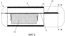
Фиг. 3 - вид сбоку изображения в разрезе вдоль линии A-А на Фиг. 2,FIG. 3 is a cross-sectional side view along the line AA in FIG. 2
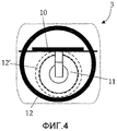
Фиг. 4 - вид спереди изображения в разрезе вдоль линии B-B на Фиг. 3,FIG. 4 is a front view of a sectional view along the line B-B in FIG. 3
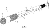
Фиг. 5 - изображение в разобранном виде, показывающее отдельные части устройства согласно изобретению, аFIG. 5 is an exploded view showing individual parts of a device according to the invention, and
Фиг. 6 - схематичный чертеж элементов устройства.FIG. 6 is a schematic drawing of elements of a device.
Необходимо учитывать, что изобретение не ограничено следующими вариантами осуществления, которые отображают всего лишь один из возможных вариантов осуществления изобретения. Кроме того, следует заметить, что изображения на фигурах с целью упрощения являются только схематичными.It should be borne in mind that the invention is not limited to the following embodiments that display only one of the possible embodiments of the invention. In addition, it should be noted that the images in the figures for the purpose of simplification are only schematic.
Фиг. 1 показывает вид в разрезе коровы 1, при этом корова 1 в данном случае служит только в качестве примера сельскохозяйственного животного, в желудочно-кишечный тракт которого может быть вставлено устройство. Примерами других подходящих сельскохозяйственных животных являются, например, овцы, козы и дикие жвачные животные, такие как благородный олень.FIG. 1 shows a sectional view of a cow 1, wherein cow 1 in this case serves only as an example of a farm animal in which a device can be inserted into the gastrointestinal tract. Examples of other suitable farm animals are, for example, sheep, goats, and wild ruminants such as red deer.
Корм, проглатываемый и пережевываемый коровой 1, заканчивает свой путь в желудке коровы 1, например, в рубце или ретикулуме 2. Ретикулум 2 является частью желудка коровы 1, расположенной перед рубцом. Из ретикулума 2 проглатываемые корма либо продвигаются вперед в рубец, либо назад в рот коровы 1 для пережевывания жвачки.The food swallowed and chewed by cow 1 ends in the stomach of cow 1, for example, in the rumen or
Корма в желудке коровы 1 можно разделить приблизительно на три фазы: вверху находится газообразная фаза, содержащая CO2 и метан (CH4). В середине находится твердая фаза, так называемый "волокнистый мат", содержащий предварительно переваренное сено, силос из злаковых трав и т.д. В нижней части находится текучая среда рубца, состоящая из жидкостей, таких как кислоты, микроорганизмы, слюнная жидкость, вода и пережевываемый материал. Измерение физиологических параметров содержимого желудка предоставляет возможность сделать заключение о возможном воздействии и/или заключения, касающиеся состояния здоровья животного - в случае, когда pH низкий, может возникнуть, например, ацидоз рубца. Измерительное устройство 3 согласно изобретению, таким образом, помещено в желудочно-кишечном тракте животного, т.е. в представленном примере в области ретикулума 2 коровы 1 для того, чтобы зафиксировать физиологические данные желудка.The feed in the stomach of cow 1 can be divided into approximately three phases: at the top there is a gaseous phase containing CO 2 and methane (CH 4 ). In the middle is a solid phase, the so-called "fiber mat", containing pre-digested hay, a silage from cereal grass, etc. At the bottom is a rumen fluid consisting of liquids such as acids, microorganisms, salivary fluid, water and chewed material. Measurement of the physiological parameters of the contents of the stomach provides an opportunity to make a conclusion about the possible effects and / or conclusions regarding the health status of the animal - in the case when the pH is low, for example, acidosis of the scar can occur. The measuring
Фиг. 2, 3 и 4 показывают измерительное устройство 3 согласно изобретению на различных изображениях в разрезе. Измерительное устройство 3 вставляют в желудочно-кишечный тракт пережевывающего жвачку сельскохозяйственного животного с помощью подходящего средства и оставляют там. Для введения измерительного устройства 3 используют, например, устройство для введения пилюль, общеизвестное в области животноводства.FIG. 2, 3 and 4 show a
Фиг. 2 показывает вид сверху сечения вдоль продольной оси измерительного устройства 3 изобретения, упоминаемого далее также, как болюс, при этом используется то же самое ссылочное обозначение, что и для измерительного устройства 3.FIG. 2 shows a top view of a section along the longitudinal axis of the measuring
Корпус 4 болюса 3 имеет цилиндрическую форму с закругленными кромками больших радиусов, при этом необходимо избегать наружных заусенцев для того, чтобы минимизировать риск повреждения животного. Материалами для корпуса 4 предпочтительно являются стойкие к кислоте ударопрочные пластмассы, которые в идеале согласуются с правилами Америнского Управления по Продовольствию и Медикаментам (FDA). Корпус 4 не должен неравномерно разламываться при нагрузке ниже определенного порогового значения. При выборе пластмассы, которая должна использоваться, необходимо принимать в расчет кислую среду желудочно-кишечного тракта животного.The
Корпус 4 является фиксируемым и может, с данной целью, состоять из нескольких частей, например из двух или трех взаимно фиксируемых частей (см. Фиг. 5). Корпус 4 содержит устройства, необходимые для измерения физиологических параметров. Данные устройства расположены на печатной плате 5 (PCB). На Фиг. 2 не проиллюстрирована точная компоновка, поскольку возможен ряд компоновок, которые являются хорошо известными квалифицированному специалисту в данной области. Ссылка сделана только на одну область 6 печатной платы 5, в которой расположены отдельные составные элементы.The
Фиг. 6 показывает схематичный чертеж с составными элементами устройства 3 изобретения и их соединениями. Составные элементы расположены в корпусе 4. Корпус содержит блок 7 управления для управления измерительным устройством 3. Это может, например, быть достигнуто с использованием должным образом запрограммированного микропроцессора. Блок 7 управления управляет и обрабатывает данные от датчиков 8, 8'. Для сохранения данных может быть предоставлен блок 16 памяти, например, кристалл запоминающего устройства или SD карта. Должен быть предоставлен, по меньшей мере, один датчик 8, 8', однако также могут использоваться более чем два датчика. Датчики 8, 8' измеряют окружающие их параметры, такие как pH и температура. Однако соответствующим образом также могут быть предусмотрены датчики для измерения глюкозы, летучих жирных кислот (особенно смешанных жирных кислот), ацетата, пропионата, бутирата и лактата. Датчики 8, 8' установлены таким образом, чтобы быть способными вступать в контакт со средой, окружающей измерительное устройство 3, например, через отверстия (не проиллюстрированые на фигурах).FIG. 6 shows a schematic drawing with the constituent elements of the
Данные обрабатываются блоком 7 управления. Посредством передающего устройства 9, оборудованного антенной 10, данные передаются беспроводным способом, например, на базовую станцию, расположенную снаружи животного. Предпочтительно, передатчик 9 выполнен в виде приемопередающего устройства 9, которое способно как передавать, так и получать данные. Следовательно, в последующем будет использоваться термин приемопередатчик 9.Data is processed by the control unit 7. By means of a
Посредством антенны 10 и приемопередатчика 9 имеется возможность воздействия на блок 7 управления снаружи, например, для того, чтобы модифицировать выполнение внутренней программы. Антенна 10 может быть выполнена различными способами, например, в виде спиральной антенны или винтообразной антенны, или в виде керамической и/или микрополосковой антенны.By means of the
Приемопередатчик 9 функционирует на частоте, варьирующейся от 20 МГц до 1 ГГц. Частотные диапазоны, которые часто используются в аналогичных вариантах применения, варьируют от 300 МГц до 450 МГц. В Европе, например, используется частота 433 МГц. Для применения в США может использоваться частота 315 МГц. Однако другие используемые ISM-радиодиапазоны (Промышленный, Научный и Медицинский диапазон) лежат в интервале, равном 868 МГц или 915 МГц. Также может использоваться частота 27 МГц.The
Также возможен приемопередатчик 9, который может быть выполнен в виде транспондера с радиочастотной идентификацией. В данном случае, в зависимости от варианта его конструкции, в транспондере с радиочастотной идентификацией может содержаться антенна, переключающая цепь для передачи (и получения) данных, цепь для регулирования транспондера, а также память, например, в виде тега. Переключающая цепь для управления транспондером записывает данные в память (например, тег). В специальной конструкции данная переключающая цепь может быть расположена снаружи транспондера с радиочастотной идентификацией, в представленном случае, например, в виде части блока 7 управления на печатной схеме 5. Считывание с транспондера с радиочастотной идентификацией затем осуществляется с помощью стимулирования посредством высокочастотного переменного поля. В подобном случае транспондер с радиочастотной идентификацией должен быть соответствующим образом расположен на печатной плате 5.It is also
При использовании транспондера с радиочастотной идентификацией данные передаются в частотном диапазоне, составляющем от 128 кГц (длинноволновый диапазон) до 13,56 МГц (коротковолновый диапазон), или в диапазоне, равном от 865-869 МГц (Европейский диапазон) до 950 МГц (частотные диапазоны США и азиатские). Частота может варьироваться от одного региона к другому.When using a transponder with radio frequency identification, data is transmitted in the frequency range of 128 kHz (long wavelength range) to 13.56 MHz (short wavelength range), or in the range of 865-869 MHz (European range) to 950 MHz (frequency ranges USA and Asian). Frequency may vary from one region to another.
Что касается обсуждения размера конструкции и других характеристик, то имеется возможность выбора из ряда хорошо известных решений.As for the discussion of the size of the structure and other characteristics, it is possible to choose from a number of well-known solutions.
Устройством подачи электроэнергии может быть батарея 11 или аккумулятор.The power supply device may be a
Антенна 10 на Фиг. 2 выполнена в виде имеющей форму меандра антенны. Она состоит из нескольких петель подходящего материала-носителя, которые расположены на уровне печатной платы 5. Антенна 10 в упомянутой конструкции обеспечивает возможность оптимального компромисса между диаграммой направленности в вертикальной и горизонтальной плоскостях поляризации, необходимой адаптацией и эффективного по затратам изготовления. Имеющая форму меандра антенна может быть оптимизирована для прямого соединения основания антенны с печатной платой 5 таким образом, чтобы не было необходимости в дополнительной адаптации, что дополнительно снижает производственные издержки.
Фиг. 3 показывает боковое поперечное сечение измерительного устройства 3 вдоль линии A-А на Фиг. 2. Она показывает, что батарея 11 расположена под печатной платой 5 внутри корпуса 4. Однако иллюстрация батареи 11 и ее компоновка приведены только в качестве примера; также она может быть выполнена с любой другой формой в соответствии с широко известными формами батарей или аккумуляторов.FIG. 3 shows a lateral cross-section of the measuring
Используемые блоки снабжения электроэнергией, например литиевые батареи, как правило, имеют в своем составе вещества, которые являются потенциально вредными для домашнего скота. Вследствие этого устройство 3 изобретения выполнено с возможностью содержания полого защитного кожуха 12, закрывающего, по меньшей мере, батарею 11 для того, чтобы защитить его от механического воздействия. Подобное воздействие может возникнуть, например, когда корова 1 отрыгивает измерительное устройство 3 назад в рот вместе с кормом, подлежащим пережевыванию, а затем перекусывает измерительное устройство 3.Used power supply units, such as lithium batteries, typically contain substances that are potentially harmful to livestock. As a consequence, the
Предпочтительно, кожух 12 выполнен цилиндрической формы. В изображенном варианте осуществления цилиндр имеет круглое поперечное сечение (см. Фиг. 4), однако поперечное сечение может также иметь полигональную форму. В идеале как верхняя, так и нижняя плоскости являются открытыми, так что приспособления, подлежащие защите, легко вставлять в устройство. Защитный кожух 12 может быть сделан из любого материала, который оказывает сопротивление сильному механическому воздействию, например, из пластмассовых материалов, таких как Kevlar™, или металлов, таких как латунь или аналогичные металлы.Preferably, the
В проиллюстрированном варианте осуществления защитный кожух 12 окружает не только блок 11 снабжения электроэнергией, но также и большую часть печатной платы 5 с упомянутыми выше составными элементами (например, упомянутым также выше транспондером с радиочастотной идентификацией). Предпочтительно, антенна 10 расположена снаружи защитного кожуха 12, для того, чтобы минимизировать повреждение диаграммы направленности, которое является значительным, особенно, когда для защитного кожуха 12 используется металлический материал. Фиг. 4 показывает вариант изобретения с пунктирным контуром, в котором защитный кожух 12' окружает только батарею 11. В подобном случае защитный кожух 12 повышенного диаметра может быть исключен, однако возможно предусмотреть комбинацию защитного кожуха 12' для батареи и еще одного большего защитного кожуха 12, окружающего его.In the illustrated embodiment, the
Защитный кожух 12 служит как в качестве защиты от механического воздействия ("защита от укусов"), так и в качестве дополнительной массы, предоставляя устройству 3 достаточную плотность для того, чтобы оно оставалось в местоположении в желудочно-кишечном тракте, которое подходит для приема данных датчиками 8, 8'. Если защитный кожух 12 изготовлен из металла, это может улучшить диаграмму направленности антенны 10 путем изменения электромагнитного поля вблизи антенны 10.The
В дополнение к функции "защита от перекусывания" защитный кожух 12 вносит вклад в массу устройства 3. Масса, т.е. конкретная сила тяжести (плотность) измерительного устройства 3 чрезвычайно важна для правильного позиционирования устройства 3 в желудочно-кишечном тракте обсуждаемого сельскохозяйственного животного. Таким образом, на массу всего измерительного устройства 3 может оказывать влияние выбранный материал и толщина защитного кожуха 12. Например, также возможно изменять толщину защитного кожуха 12 по длине.In addition to the “anti-bite protection” function, the
Для того чтобы дополнительно увеличить массу измерительного устройства 3, есть возможность заполнить внутреннюю часть корпуса 4 термореактивным материалом, таким как синтетическая смола. При заполнении материалом антенну 10 в идеале оставляют для того, чтобы обеспечить правильную передачу данных.In order to further increase the weight of the measuring
В изображенном варианте осуществления изобретения устройство 3 оборудовано переключателем. Переключатель, в сущности, может быть выполнен с любой формой - в данном случае переключатель состоит из двух металлических контактов 13, например, из нержавеющей стали, которые соединены с блоком 7 управления. Данные контакты выступают из устройства 3 через отверстия 14 в корпусе 4 (см. Фиг. 2 и 5). Измерительное устройство 3 активируется посредством короткого замыкания контактов 13 в течение определенного периода времени - в интервале от нескольких миллисекунд до нескольких секунд.In the illustrated embodiment,
Состоянием предыдущего уровня техники является замыкание контактов 13 внутри блока 7 управления, который необходим для этого. Например, контакты 13 могут быть соединены с пусковой схемой в блоке 7 управления, который содержит два МОП-транзистора (полевой транзистор со структурой металл-оксид-полупроводник), при этом один из МОП-транзисторов соединен с контактами 13. Посредством короткого замыкания контактов 13 второй МОП-транзистор переключает напряжение батареи на схему внутри блока 7 управления, которая посредством этого активирует измерительное устройство 3.The state of the prior art is the closure of the
Для того чтобы облегчить процесс короткого замыкания для пользователя, может быть предоставлена подставка, в которую может быть помещено измерительное устройство 3, активируя, таким образом, измерительное устройство 3 посредством короткого замыкания контактов.In order to facilitate the short circuit process for the user, a stand may be provided in which the
Переключатель описанной выше конструкции обеспечивает только активацию измерительного устройства 3, которая продолжается до конца времени работы батареи, и/или до момента времени предварительно заданного выключения. В сущности, для того чтобы активировать и деактивировать измерительное устройство 3, может быть предусмотрен любой другой тип переключателей. Для этой цели в предыдущем уровне техники имеется широкий выбор переключателей.The switch of the design described above provides only the activation of the measuring
В варианте изобретения используется магнитный переключатель 13', который расположен внутри измерительного устройства 3 (см. пунктирный объект на Фиг. 6). Магнитный переключатель 13' в данном случае означает переключатель, который может быть переключен с помощью магнитного поля. Примером подобного магнитного переключателя 13' является герконовый переключатель. В сущности, магнитный переключатель 13' имеет два контакта, которые расположены в защитной атмосфере и не соприкасаются друг с другом. Однако, при применении магнитного поля, два контактных язычка притягиваются и касаются друг друга, последовательно замыкая цепь.In an embodiment of the invention, a magnetic switch 13 'is used, which is located inside the measuring device 3 (see the dotted object in Fig. 6). The magnetic switch 13 'in this case means a switch that can be switched using a magnetic field. An example of such a magnetic switch 13 'is a reed switch. In essence, the magnetic switch 13 'has two contacts that are located in a protective atmosphere and do not touch each other. However, when applying a magnetic field, two contact tongues attract and touch each other, sequentially closing the circuit.
Магнитный переключатель 13' может быть объединен со вторым МОП-транзистором, как описано выше, таким образом, что переключение магнитного переключателя 13' соединяет напряжение батареи с остальной частью цепи в блоке 7 управления, активируя посредством этого измерительное устройство 3.The magnetic switch 13 'can be combined with the second MOS transistor, as described above, so that switching the magnetic switch 13' connects the battery voltage to the rest of the circuit in the control unit 7, thereby activating the measuring
Переключение магнитного переключателя 13' может быть осуществлено за счет применения магнитного поля в конкретном положении измерительного устройства 3, например, посредством прикрепления постоянного магнита или электромагнита.Switching of the magnetic switch 13 'can be accomplished by applying a magnetic field in a specific position of the measuring
Фиг. 5 показывает отдельные составные элементы измерительного устройства 3 изобретения в изображении в разобранном виде. В данном случае корпус состоит из трех частей: передней части 41 корпуса (которая, например, может быть выполнена с возможностью содержания отверстий для датчиков 8, 8'), центральной части 42 корпуса, вмещающей печатную плату 5, и задней части 43 корпуса, при этом части являются взаимосвязанными. Конструкция корпуса из трех частей с частями 41, 42, 43 в данном случае служит только в качестве примера - конструкция может предусматривать больше или меньше частей корпуса. Для того чтобы облегчить введение измерительного устройства 3 в животное, задняя часть 43 корпуса может иметь плоский конец, который взаимодействует с подвижным концом болюсодавателя, который используется для вставки устройства таким образом, чтобы измерительное устройство 3 правильно продвигалось в рубец и не застревало.FIG. 5 shows the individual components of the measuring
В дополнение к описанным выше составным элементам (которые не показаны на фигурах) плата 5 печатной схемы включает в себя имеющую форму меандра антенну 10 и контакты 13. Плата 5 печатной схемы удерживается на своем месте посредством подставки 15 и снабжается электроэнергией посредством батареи 11. Защитный кожух 12 может быть размещен вокруг данных составных элементов.In addition to the components described above (which are not shown in the figures), the printed
Задняя часть корпуса 43 содержит отверстия для контактов 13.The back of the
При активации и введении в желудочно-кишечный тракт животного измерительное устройство 3 выполняет измерения в определенные временные интервалы. Данные интервалы могут варьироваться от 1 с до нескольких часов или даже дней. Измеренные данные сохраняются в блоке 16 хранения, например в кристалле запоминающего устройства - ЭСППЗУ, SD памяти или флеш-памяти. Если устройство 3 содержит транспондер с радиочастотной идентификацией, данные могут быть сохранены в памяти транспондера. Также возможно непосредственно передавать данные беспроводным образом наружу.When activated and introduced into the gastrointestinal tract of the animal, the measuring
Если измерительное устройство 3 используется в виде части системы вместе с, по меньшей мере, одной базовой станцией, подобная базовая станция регулярно ищет измерительные устройства в пределах своей зоны доступа с помощью поисковой команды. Расстояние между измерительным устройством и базовой станцией в данном случае составляет, например, от 5 до 6 м или меньше. Как только измерительное устройство 3 попадает в пределы зоны доступа, оно самоидентифицируется посредством идентификатора (серийного номера, номера болюса и тому подобного). После этого базовая станция проверяет, содержит ли измерительное устройство 3 какие-либо вновь измеренные данные. В этом случае измеренные данные считываются, сохраняются в базовой станции (например, в базе данных), а затем удаляются из измерительного устройства 3. Затем базовая станция обрабатывает измеренные данные посредством соответствующих процедур таким образом, чтобы обеспечивать возможность быстрой оценки данных. Подобная оценка может, например, привести к изменению рациона даваемого корма.If the measuring
Claims (13)
- по меньшей мере, один датчик (8, 8') для измерения, по меньшей мере, одного физиологического параметра организма сельскохозяйственного животного;
- по меньшей мере, один передатчик (9) с антенной (10) для беспроводной передачи информации,
- по меньшей мере, один блок (7) управления для управления измерительным устройством (3), и
- по меньшей мере, одно устройство (11) подачи электроэнергии для измерительного устройства (3),
отличающееся тем, что корпус содержит полый защитный кожух (12, 12'), закрывающий, по меньшей мере, устройство (11) подачи электроэнергии для того, чтобы обеспечить защиту от механического воздействия.1. A measuring device (3) for measuring at least one physiological parameter of the organism of an agricultural animal, while the measuring device (3) is arranged to be placed in the gastrointestinal tract of an agricultural animal and contains the following elements located inside the housing (4) :
- at least one sensor (8, 8 ') for measuring at least one physiological parameter of the organism of the farm animal;
- at least one transmitter (9) with an antenna (10) for wireless transmission of information,
at least one control unit (7) for controlling the measuring device (3), and
- at least one device (11) for supplying electricity to the measuring device (3),
characterized in that the housing comprises a hollow protective casing (12, 12 ') covering at least the power supply device (11) in order to provide protection against mechanical stress.
Applications Claiming Priority (3)
| Application Number | Priority Date | Filing Date | Title |
|---|---|---|---|
| ATA2052/2009 | 2009-12-30 | ||
| AT0205209A AT509255B1 (en) | 2009-12-30 | 2009-12-30 | DEVICE FOR MEASURING INDIVIDUAL DATA |
| PCT/AT2010/000490 WO2011079338A2 (en) | 2009-12-30 | 2010-12-22 | Device for the measurement of individual farm animal data |
Publications (2)
| Publication Number | Publication Date |
|---|---|
| RU2012132453A RU2012132453A (en) | 2014-02-10 |
| RU2548878C2 true RU2548878C2 (en) | 2015-04-20 |
Family
ID=44226848
Family Applications (1)
| Application Number | Title | Priority Date | Filing Date |
|---|---|---|---|
| RU2012132453/13A RU2548878C2 (en) | 2009-12-30 | 2010-12-22 | Device for measuring data of individual farm animal |
Country Status (9)
| Country | Link |
|---|---|
| US (1) | US9504231B2 (en) |
| EP (1) | EP2519098B1 (en) |
| AT (1) | AT509255B1 (en) |
| BR (1) | BR112012016375B1 (en) |
| CA (1) | CA2785925C (en) |
| RU (1) | RU2548878C2 (en) |
| UA (1) | UA106644C2 (en) |
| WO (1) | WO2011079338A2 (en) |
| ZA (1) | ZA201204642B (en) |
Cited By (3)
| Publication number | Priority date | Publication date | Assignee | Title |
|---|---|---|---|---|
| RU2725728C1 (en) * | 2019-07-22 | 2020-07-03 | Открытое акционерное общество "Авангард" | Method for radio-frequency identification of large and small cattle and device for implementation thereof |
| US11426703B2 (en) | 2017-06-20 | 2022-08-30 | Zelp Ltd | Gas processing device and method |
| RU2784518C2 (en) * | 2017-06-20 | 2022-11-28 | Зелп Лтд | Gas-recycling device |
Families Citing this family (28)
| Publication number | Priority date | Publication date | Assignee | Title |
|---|---|---|---|---|
| EP2478503A4 (en) | 2009-09-15 | 2017-09-27 | Bella Technologies, LLC | Computer implemented animal management system |
| NZ708284A (en) | 2010-10-19 | 2015-10-30 | Bella Technologies Llc | Animal monitoring system |
| EP2724670B1 (en) | 2012-10-26 | 2015-06-17 | Pekka Kankfelt | Detecting altered pH levels of rumens |
| US10033469B2 (en) | 2013-08-29 | 2018-07-24 | Battelle Memorial Institute | Injectable acoustic transmission devices and process for making and using same |
| US10033470B2 (en) | 2013-08-29 | 2018-07-24 | Battelle Memorial Institute | Acoustic transmission devices and process for making and using same |
| US10101429B2 (en) | 2015-02-25 | 2018-10-16 | Battelle Memorial Institute | Acoustic transmission device and process for tracking selected hosts |
| US10231644B2 (en) | 2015-06-12 | 2019-03-19 | St Reproductive Technologies Llc | Calf bolus |
| US10067112B2 (en) | 2015-09-30 | 2018-09-04 | Battelle Memorial Institute | Autonomous sensor fish to support advanced hydropower development |
| NZ743053A (en) | 2015-11-30 | 2022-10-28 | Jvd Inc | Medicine delivery and animal management systems |
| US11278004B2 (en) | 2015-12-15 | 2022-03-22 | Battelle Memorial Institute | Transmitters for animals and methods for transmitting from animals |
| US10236920B2 (en) | 2015-12-15 | 2019-03-19 | Battelle Memorial Institute | Signal transmitter and methods for transmitting signals from animals |
| US10306868B2 (en) | 2015-12-15 | 2019-06-04 | St Reproductive Technologies, Llc | Animal environmental and physiological monitoring system |
| WO2017103239A1 (en) | 2015-12-18 | 2017-06-22 | Dropnostix Gmbh | Device for measuring the gastric pressure and the gastric motility of a livestock animal |
| AT517847B1 (en) * | 2016-01-22 | 2017-05-15 | Smaxtec Animal Care Sales Gmbh | Probe unit for measuring at least one state variable of the organism of a farm animal and method for their commissioning |
| US10531639B2 (en) | 2016-08-25 | 2020-01-14 | Battelle Memorial Institute | Systems and methods for monitoring organisms within an aquatic environment |
| US11056774B2 (en) | 2017-04-28 | 2021-07-06 | Herdstrong | Autotune bolus antenna |
| US11553442B2 (en) | 2017-04-28 | 2023-01-10 | Herdstrong Llc. | Hopping scheme for embedded wireless sensors |
| US10390515B2 (en) | 2017-04-28 | 2019-08-27 | Herdstrong Llc | Bolus antenna system |
| US11020576B2 (en) * | 2018-04-11 | 2021-06-01 | Jvd, Inc. | Medicine delivery and animal management systems |
| AT521597B1 (en) | 2018-11-13 | 2020-03-15 | Smaxtec Animal Care Gmbh | Method, device and system for determining at least one state variable of the organism of a farm animal |
| GB2581205A (en) | 2019-02-08 | 2020-08-12 | Agtag Ltd | Bovine motion sensor tag |
| US11533818B2 (en) | 2019-03-12 | 2022-12-20 | Battelle Memorial Institute | Sensor assemblies and methods for emulating interaction of entities within water systems |
| US11688154B2 (en) | 2020-05-28 | 2023-06-27 | X Development Llc | Analysis and sorting in aquaculture |
| US11582948B2 (en) * | 2020-07-21 | 2023-02-21 | Garrity Power Services Llc | Cattle tracking system |
| WO2022220317A1 (en) * | 2021-04-14 | 2022-10-20 | 주식회사 유라이크코리아 | Ingestible health sensor for animal |
| US11307728B1 (en) | 2021-04-26 | 2022-04-19 | Inguran, Llc | Computerized systems and methods for livestock management |
| WO2023091042A1 (en) * | 2021-11-16 | 2023-05-25 | Общество С Ограниченной Ответственностью Инжиниринговый Центр Миэт | Method and device for measuring physiological parameters of cattle |
| AT526013A1 (en) | 2022-03-22 | 2023-10-15 | Smaxtec Animal Care Gmbh | Probe device for measuring at least one state variable of the organism of a farm animal |
Citations (2)
| Publication number | Priority date | Publication date | Assignee | Title |
|---|---|---|---|---|
| RU2063778C1 (en) * | 1993-05-31 | 1996-07-20 | Курский научно-исследовательский институт агропромышленного производства | Gastric tube-sensor |
| RU6519U1 (en) * | 1997-03-19 | 1998-05-16 | Курский научно-исследовательский институт агропромышленного производства | PROBE SENSOR MULTIFUNCTIONAL |
Family Cites Families (21)
| Publication number | Priority date | Publication date | Assignee | Title |
|---|---|---|---|---|
| US5111799A (en) * | 1990-03-28 | 1992-05-12 | Washington State University Research Foundation, Inc. | Estrous detection systems |
| IE913238A1 (en) * | 1991-09-13 | 1993-03-24 | Rodney Arthur Stafford | Electronic animal identification system |
| WO1998001025A1 (en) * | 1996-07-09 | 1998-01-15 | The European Community | Ruminal bolus for electronic identification of a ruminant |
| US6012415A (en) * | 1997-04-18 | 2000-01-11 | Magtronic Id, Inc. | Bolus with animal ID and temperature transponder |
| US5984875A (en) | 1997-08-22 | 1999-11-16 | Innotek Pet Products, Inc. | Ingestible animal temperature sensor |
| NL1008514C2 (en) | 1998-03-06 | 1999-09-07 | Nedap Nv | Reusable identification transponder inn the form of a bolus for stock management |
| DE19901124A1 (en) | 1999-01-14 | 2000-07-20 | Laue Hans Joachim | Assembly for controlled care and/or tending for domestic animals in agricultural operational units with large cattle stock |
| NL1012864C2 (en) | 1999-08-19 | 2001-02-20 | Nedap Nv | Measurement of the acidity in the gastric system of animals, such as cows. |
| US20020010390A1 (en) * | 2000-05-10 | 2002-01-24 | Guice David Lehmann | Method and system for monitoring the health and status of livestock and other animals |
| US6694161B2 (en) | 2001-04-20 | 2004-02-17 | Monsanto Technology Llc | Apparatus and method for monitoring rumen pH |
| US6846994B2 (en) * | 2001-09-19 | 2005-01-25 | Justin B. Wenner | System and method to delay closure of a normally closed electrical circuit |
| US20060155174A1 (en) * | 2002-12-16 | 2006-07-13 | Arkady Glukhovsky | Device, system and method for selective activation of in vivo sensors |
| US20040133131A1 (en) | 2003-01-03 | 2004-07-08 | Kuhn David L. | In vivo ruminant health sensor |
| JP2005192821A (en) * | 2004-01-07 | 2005-07-21 | Olympus Corp | Capsule type medical apparatus |
| WO2005104930A1 (en) | 2004-04-30 | 2005-11-10 | Biowatch Pty Ltd | Animal health monitoring system |
| EP1763860A4 (en) * | 2004-09-03 | 2012-11-07 | Semiconductor Energy Lab | Health data collecting system and semiconductor device |
| GB0423928D0 (en) | 2004-10-27 | 2004-12-01 | Well Cow Ltd | Parameter monitoring system |
| US20080236500A1 (en) * | 2007-02-20 | 2008-10-02 | Hodges Terry E | Apparatus, system, and method for animal monitor |
| GB2455700B (en) * | 2007-10-10 | 2011-12-28 | Ecow Ltd | Bolus |
| US20090182207A1 (en) * | 2008-01-16 | 2009-07-16 | Tenxsys Inc. | Ingestible animal health sensor |
| AU2009202778B2 (en) * | 2008-07-11 | 2014-05-08 | Commonwealth Of Australia As Represented By And Acting Through The Department Of The Environment, Water, Heritage And The Arts | Improved baiting method and composition |
-
2009
- 2009-12-30 AT AT0205209A patent/AT509255B1/en active
-
2010
- 2010-12-22 BR BR112012016375-2A patent/BR112012016375B1/en active IP Right Grant
- 2010-12-22 WO PCT/AT2010/000490 patent/WO2011079338A2/en active Application Filing
- 2010-12-22 EP EP10808965.7A patent/EP2519098B1/en active Active
- 2010-12-22 RU RU2012132453/13A patent/RU2548878C2/en active
- 2010-12-22 CA CA2785925A patent/CA2785925C/en active Active
- 2010-12-22 US US13/520,101 patent/US9504231B2/en active Active
- 2010-12-22 UA UAA201209263A patent/UA106644C2/en unknown
-
2012
- 2012-06-22 ZA ZA2012/04642A patent/ZA201204642B/en unknown
Patent Citations (2)
| Publication number | Priority date | Publication date | Assignee | Title |
|---|---|---|---|---|
| RU2063778C1 (en) * | 1993-05-31 | 1996-07-20 | Курский научно-исследовательский институт агропромышленного производства | Gastric tube-sensor |
| RU6519U1 (en) * | 1997-03-19 | 1998-05-16 | Курский научно-исследовательский институт агропромышленного производства | PROBE SENSOR MULTIFUNCTIONAL |
Cited By (3)
| Publication number | Priority date | Publication date | Assignee | Title |
|---|---|---|---|---|
| US11426703B2 (en) | 2017-06-20 | 2022-08-30 | Zelp Ltd | Gas processing device and method |
| RU2784518C2 (en) * | 2017-06-20 | 2022-11-28 | Зелп Лтд | Gas-recycling device |
| RU2725728C1 (en) * | 2019-07-22 | 2020-07-03 | Открытое акционерное общество "Авангард" | Method for radio-frequency identification of large and small cattle and device for implementation thereof |
Also Published As
| Publication number | Publication date |
|---|---|
| CA2785925C (en) | 2019-10-22 |
| WO2011079338A3 (en) | 2011-11-24 |
| UA106644C2 (en) | 2014-09-25 |
| AT509255A1 (en) | 2011-07-15 |
| BR112012016375A2 (en) | 2017-05-02 |
| BR112012016375B1 (en) | 2018-02-06 |
| AT509255B1 (en) | 2012-03-15 |
| RU2012132453A (en) | 2014-02-10 |
| EP2519098A2 (en) | 2012-11-07 |
| EP2519098B1 (en) | 2015-01-21 |
| ZA201204642B (en) | 2013-03-27 |
| US20120277550A1 (en) | 2012-11-01 |
| WO2011079338A2 (en) | 2011-07-07 |
| CA2785925A1 (en) | 2011-07-07 |
| US9504231B2 (en) | 2016-11-29 |
Similar Documents
| Publication | Publication Date | Title |
|---|---|---|
| RU2548878C2 (en) | Device for measuring data of individual farm animal | |
| US6694161B2 (en) | Apparatus and method for monitoring rumen pH | |
| EP3307158B9 (en) | Calf bolus | |
| US10993668B2 (en) | Sampling device | |
| GB2455700A (en) | Bolus with ph and temperature sensor | |
| US5697384A (en) | Internal identification apparatus for animals | |
| CA2286629A1 (en) | Bolus with animal id and temperature transponder | |
| US5111799A (en) | Estrous detection systems | |
| US7533482B2 (en) | Metal ear tag with electronic identification device | |
| US20080236500A1 (en) | Apparatus, system, and method for animal monitor | |
| US20040233971A1 (en) | Temperature recording system | |
| EP2493287B1 (en) | Bolus system | |
| JP4663598B2 (en) | Feeding device and feeding method | |
| JPH1075680A (en) | Monitoring of sexual excitement or the like of livestock | |
| KR200438407Y1 (en) | RFID Capsule and Microwave ID Capsule having Temperature Sensor therein | |
| Schoenig et al. | Ambulatory instrumentation suitable for long-term monitoring of cattle health | |
| US20200397292A1 (en) | Device for the remote monitoring of body temperature in cattle and pigs | |
| CA2886522A1 (en) | Intravaginal sensor and methods for selecting an insemination time | |
| KR20160123418A (en) | A sensor tag using domestic animal | |
| JP2022034912A (en) | Ear canal temperature sensor and method for detecting change of health condition of animal | |
| GB2495833A (en) | An ingestible monitoring device | |
| Eerdekens et al. | Automated Goat Behavior Detection Using Accelerometer and Temperature Bolus Data |
Legal Events
| Date | Code | Title | Description |
|---|---|---|---|
| HZ9A | Changing address for correspondence with an applicant | ||
| HE9A | Changing address for correspondence with an applicant | ||
| PC41 | Official registration of the transfer of exclusive right |
Effective date: 20190708 |