RU2546373C1 - Oscillating console with rotary flaps of main blade of wind and hydroelectric power plant - Google Patents
Oscillating console with rotary flaps of main blade of wind and hydroelectric power plant Download PDFInfo
- Publication number
- RU2546373C1 RU2546373C1 RU2014104625/06A RU2014104625A RU2546373C1 RU 2546373 C1 RU2546373 C1 RU 2546373C1 RU 2014104625/06 A RU2014104625/06 A RU 2014104625/06A RU 2014104625 A RU2014104625 A RU 2014104625A RU 2546373 C1 RU2546373 C1 RU 2546373C1
- Authority
- RU
- Russia
- Prior art keywords
- main blade
- console
- wind
- forks
- oscillating
- Prior art date
Links
- 238000013016 damping Methods 0.000 claims abstract description 4
- 238000009434 installation Methods 0.000 claims description 3
- 239000003351 stiffener Substances 0.000 claims description 2
- 238000012423 maintenance Methods 0.000 abstract description 2
- 230000002269 spontaneous effect Effects 0.000 abstract description 2
- 230000000694 effects Effects 0.000 abstract 1
- 239000000126 substance Substances 0.000 abstract 1
- XLYOFNOQVPJJNP-UHFFFAOYSA-N water Substances O XLYOFNOQVPJJNP-UHFFFAOYSA-N 0.000 description 3
- 230000005540 biological transmission Effects 0.000 description 1
- 230000009977 dual effect Effects 0.000 description 1
- 239000012634 fragment Substances 0.000 description 1
- 238000000034 method Methods 0.000 description 1
- 230000003449 preventive effect Effects 0.000 description 1
- 230000003014 reinforcing effect Effects 0.000 description 1
Images
Classifications
-
- Y—GENERAL TAGGING OF NEW TECHNOLOGICAL DEVELOPMENTS; GENERAL TAGGING OF CROSS-SECTIONAL TECHNOLOGIES SPANNING OVER SEVERAL SECTIONS OF THE IPC; TECHNICAL SUBJECTS COVERED BY FORMER USPC CROSS-REFERENCE ART COLLECTIONS [XRACs] AND DIGESTS
- Y02—TECHNOLOGIES OR APPLICATIONS FOR MITIGATION OR ADAPTATION AGAINST CLIMATE CHANGE
- Y02E—REDUCTION OF GREENHOUSE GAS [GHG] EMISSIONS, RELATED TO ENERGY GENERATION, TRANSMISSION OR DISTRIBUTION
- Y02E10/00—Energy generation through renewable energy sources
- Y02E10/70—Wind energy
Landscapes
- Wind Motors (AREA)
Abstract
Description
Изобретение относится к возобновляемой энергетике и может быть использовано при создании новых невращающихся преобразователей кинетической энергии для ветро- и гидроустановок, работающих в свободных воздушных или водных потоках.The invention relates to renewable energy and can be used to create new non-rotating kinetic energy converters for wind and hydraulic installations operating in free air or water flows.
Известна поворотная консоль ветро- и гидроустановки с колеблющимися вертикальными лопастями (1), содержащая кинематически связанные между собой сдвоенные основную и вспомогательную лопасти. Однако такое конструктивное решение осуществляет в крайних левом и правом положениях основной лопасти передачу крутящих моментов с существенными потерями, особенно на малых углах атаки к набегающему потоку.Known rotary console of a wind and hydraulic installation with oscillating vertical blades (1), containing kinematically coupled twin main and auxiliary blades. However, such a constructive solution implements the transmission of torques with significant losses in the extreme left and right positions of the main blade, especially at small angles of attack to the incoming flow.
Технической задачей изобретения является создание более эффективных невращающихся технических средств преобразования кинетической энергии воздушных или водных потоков с более равномерным крутящим моментом на валу многополюсного генератора, а также улучшение самопроизвольного запуска консоли после ее остановки во время бури или проведения профилактических работ.An object of the invention is the creation of more efficient non-rotating technical means of converting the kinetic energy of air or water flows with a more uniform torque on the shaft of a multipolar generator, as well as improving the spontaneous start of the console after it stops during a storm or during preventive maintenance.
Поставленная цель достигается тем, что на торцах верхней и нижней секций основной лопасти со стороны набегающего потока дополнительно размещены на концевых штифтах поворотные закрылки обтекаемой формы, удерживаемые в пределах ограничивающих углов пружинящими вилками и возвратными пружинами с регулированным натяжением.This goal is achieved in that at the ends of the upper and lower sections of the main blade on the side of the incoming flow, streamlined flap flaps are additionally placed on the end pins, held within the limiting angles by spring forks and return springs with adjustable tension.
Плоскости поворотных закрылков так же, как основной и вспомогательной лопастей, имеют простую симметричную обтекаемую форму, что в целом снижает их себестоимость и улучшает технологичность.The planes of the rotary flaps as well as the main and auxiliary blades have a simple symmetrical streamlined shape, which generally reduces their cost and improves manufacturability.
Из патентной и научно-технической информации автору не известны источники, содержащие сведения об аналогичных технических решениях, имеющих сходные признаки с заявляемым решением.From the patent and scientific and technical information, the author does not know the sources containing information about similar technical solutions having similar features with the claimed solution.
Изобретение поясняется схематическими изображениями, где:The invention is illustrated by schematic images, where:
Фиг.1 - Вид сверху на рабочие положения плоскостей лопастей и закрылков в воздушном или водном потоках.Figure 1 - Top view of the working position of the planes of the blades and flaps in the air or water flows.
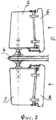
Фиг.2 - Вид сбоку на основную сдвоенную лопасть с закрылками.Figure 2 - Side view of the main dual blade with flaps.
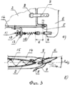
Фиг.3 - Фрагмент основной лопасти с закрылком:Figure 3 - Fragment of the main blade with a flap:
а) - вид сбоку; в) - вид сверху.a) - side view; c) - top view.
Консоль 1 содержит кинематически связанные основную 2 и вспомогательную 3 сдвоенные лопасти, размещенные на герметичном кожухе 4. На торцах каждой из секций основной лопасти 1 дополнительно размещен на двух концевых штифтах 5 поворотный закрылок 6, на котором закреплены две пружинящие вилки 7 с демпфирующими накладками 8 и стойка 9, соединенная посредством возвратной пружины 10 с резьбовой осью 11, связанной с помощью фигурной гайки 12 с уголковым кронштейном 13, посаженным на несущей пластине 14.The console 1 contains kinematically connected main 2 and auxiliary 3 twin blades placed on an airtight casing 4. At the ends of each section of the main blade 1, a
Внутри каждой из полых секций основной лопасти 2 размещены усиливающие их прочность гофрированные ребра жесткости 15, особенно в местах контакта с демпфирующими накладками 8 пружинящих вилок 7.Inside each of the hollow sections of the
Консоль работает следующим образом.The console works as follows.
Если, например, изначально ось консоли 1 находилась в среднем положении, совпадающем с направлением потока, а плоскость основной лопасти - в левом, то они совместно со вспомогательной лопастью 3 будут двигаться влево (фиг.1). С продолжением движения лопасти 2 к крайнему левому положению угол атаки ее плоскости относительно потока будет пропорционально уменьшаться и в условной точке Аз′ (в вертикальной плоскости м-м′) он будет равен нулю. Одновременно вспомогательная лопасть 3 под продолжающимся давлением на ее плоскости набегающего потока будет продолжать поворот консоли 1 влево, при этом основная лопасть 2, зайдя в отрицательный угол αл -, начнет разворот вокруг своей оси в обратную сторону, а закрылок 6 - дополнительный разворот на фиксированный угол αз - и создаст дополнительное усилие для разворота рабочей лопасти 2 на полный угол βл - и одновременного с ней разворота вспомогательной лопасти 3 на больший угол (новое взаимное положение обеих лопастей показано пунктиром). Таким образом, в диапазоне А3-Аз′ создается максимальное усилие для поворота консоли 1 вправо. Все последующие процессы с правой стороны в диапазоне А1′-A1 будут идентичны. Полный рабочий угол разворота консоли 1 в каждую сторону составляет αк ++αк - и на практике находится в пределах 50-70 градусов.If, for example, initially the axis of the console 1 was in the middle position, coinciding with the direction of flow, and the plane of the main blade in the left, then they, together with the
Необходимое рабочее натяжение возвратной пружины 10 при постоянном плече t рычага стойки 9 осуществляется с помощью поворота регулировочной фигурной гайки 12.The necessary working tension of the
Использованный источник информации Information Source Used
Патент РФ №2484298 (фиг.1 и 5).RF patent No. 2484298 (figures 1 and 5).
Claims (2)
Priority Applications (1)
| Application Number | Priority Date | Filing Date | Title |
|---|---|---|---|
| RU2014104625/06A RU2546373C1 (en) | 2014-02-10 | 2014-02-10 | Oscillating console with rotary flaps of main blade of wind and hydroelectric power plant |
Applications Claiming Priority (1)
| Application Number | Priority Date | Filing Date | Title |
|---|---|---|---|
| RU2014104625/06A RU2546373C1 (en) | 2014-02-10 | 2014-02-10 | Oscillating console with rotary flaps of main blade of wind and hydroelectric power plant |
Publications (1)
| Publication Number | Publication Date |
|---|---|
| RU2546373C1 true RU2546373C1 (en) | 2015-04-10 |
Family
ID=53295827
Family Applications (1)
| Application Number | Title | Priority Date | Filing Date |
|---|---|---|---|
| RU2014104625/06A RU2546373C1 (en) | 2014-02-10 | 2014-02-10 | Oscillating console with rotary flaps of main blade of wind and hydroelectric power plant |
Country Status (1)
| Country | Link |
|---|---|
| RU (1) | RU2546373C1 (en) |
Citations (4)
| Publication number | Priority date | Publication date | Assignee | Title |
|---|---|---|---|---|
| RU2141058C1 (en) * | 1995-11-01 | 1999-11-10 | Бакай Владимир Иванович | Method and plant for converting kinetic energy of fluid into reciprocal motion of vane |
| US20030123983A1 (en) * | 2001-12-20 | 2003-07-03 | Bolduc Maxime Lambert | Self-trimming oscillating wing system |
| GB2491839A (en) * | 2011-06-13 | 2012-12-19 | Christopher John Coxon | Oscillating wing power generator |
| RU2484298C1 (en) * | 2012-03-06 | 2013-06-10 | Виталий Григорьевич Федчишин | Wind and hydraulic unit with oscillating vertical blades |
-
2014
- 2014-02-10 RU RU2014104625/06A patent/RU2546373C1/en active
Patent Citations (4)
| Publication number | Priority date | Publication date | Assignee | Title |
|---|---|---|---|---|
| RU2141058C1 (en) * | 1995-11-01 | 1999-11-10 | Бакай Владимир Иванович | Method and plant for converting kinetic energy of fluid into reciprocal motion of vane |
| US20030123983A1 (en) * | 2001-12-20 | 2003-07-03 | Bolduc Maxime Lambert | Self-trimming oscillating wing system |
| GB2491839A (en) * | 2011-06-13 | 2012-12-19 | Christopher John Coxon | Oscillating wing power generator |
| RU2484298C1 (en) * | 2012-03-06 | 2013-06-10 | Виталий Григорьевич Федчишин | Wind and hydraulic unit with oscillating vertical blades |
Similar Documents
| Publication | Publication Date | Title |
|---|---|---|
| CN103899492B (en) | A kind of floating sea formula wind-power hydraulic TRT | |
| CN102392775B (en) | Pitch varying mechanism for horizontal shaft ocean current energy generator | |
| TW201602452A (en) | Fluid mechanic blade device | |
| NO812451L (en) | WIND ROTOR. | |
| WO2013106075A3 (en) | Novel systems for increasing efficiency and power output of in-conduit hydroelectric power system and turbine | |
| US20190024628A1 (en) | Wind turbine blade, tubular structure for wind turbine blade, wind turbine and wind-utilization monitoring method | |
| KR20150097519A (en) | Hydroelectric power plant for exploiting the energy of guided or unrestricted water flows | |
| RU2546373C1 (en) | Oscillating console with rotary flaps of main blade of wind and hydroelectric power plant | |
| CN104454362B (en) | Reciprocating type wind power generation system | |
| CN205838310U (en) | A kind of wind generator set blade hanging apparatus | |
| CN103790774B (en) | A kind of vertical axis windmill of frontal area adjustable | |
| CN202628380U (en) | Angle-changing high-efficiency wind power generator | |
| CN207080313U (en) | A tidal current power generation device based on hydraulic transmission | |
| CN102583447A (en) | Wind-driven water pumping evaporation vehicle | |
| MY206839A (en) | Wind power installation | |
| US9790915B2 (en) | Turbine for a flow power plant | |
| CN210460945U (en) | Telescopic wind turbine blade | |
| RU2447320C2 (en) | Device for renewable energy conversion | |
| RU2613476C1 (en) | Surf hydroelectric power plant | |
| RU128903U1 (en) | WIND POWER PLANT | |
| EA201400083A1 (en) | TURBINE FOR WIND MOTORS | |
| CN202482080U (en) | Wind power pumping-out evaporation vehicle | |
| CN104806447A (en) | Mechanical wind pressure variable pitch device of mini-sized wind turbine | |
| CN100424336C (en) | Drag reduction wind turbine | |
| CN207377695U (en) | Runner and the hydraulic turbine |