RU2545242C1 - Wheel rim assembly and method of wheel assembly - Google Patents
Wheel rim assembly and method of wheel assembly Download PDFInfo
- Publication number
- RU2545242C1 RU2545242C1 RU2013139686/11A RU2013139686A RU2545242C1 RU 2545242 C1 RU2545242 C1 RU 2545242C1 RU 2013139686/11 A RU2013139686/11 A RU 2013139686/11A RU 2013139686 A RU2013139686 A RU 2013139686A RU 2545242 C1 RU2545242 C1 RU 2545242C1
- Authority
- RU
- Russia
- Prior art keywords
- hub
- wheel
- end part
- flange
- rim
- Prior art date
Links
Images
Classifications
-
- B—PERFORMING OPERATIONS; TRANSPORTING
- B60—VEHICLES IN GENERAL
- B60B—VEHICLE WHEELS; CASTORS; AXLES FOR WHEELS OR CASTORS; INCREASING WHEEL ADHESION
- B60B11/00—Units comprising multiple wheels arranged side by side; Wheels having more than one rim or capable of carrying more than one tyre
- B60B11/02—Units of separate wheels mounted for independent or coupled rotation
-
- B—PERFORMING OPERATIONS; TRANSPORTING
- B60—VEHICLES IN GENERAL
- B60B—VEHICLE WHEELS; CASTORS; AXLES FOR WHEELS OR CASTORS; INCREASING WHEEL ADHESION
- B60B35/00—Axle units; Parts thereof ; Arrangements for lubrication of axles
- B60B35/12—Torque-transmitting axles
- B60B35/121—Power-transmission from drive shaft to hub
- B60B35/122—Power-transmission from drive shaft to hub using gearings
- B60B35/125—Power-transmission from drive shaft to hub using gearings of the planetary type
-
- B—PERFORMING OPERATIONS; TRANSPORTING
- B60—VEHICLES IN GENERAL
- B60K—ARRANGEMENT OR MOUNTING OF PROPULSION UNITS OR OF TRANSMISSIONS IN VEHICLES; ARRANGEMENT OR MOUNTING OF PLURAL DIVERSE PRIME-MOVERS IN VEHICLES; AUXILIARY DRIVES FOR VEHICLES; INSTRUMENTATION OR DASHBOARDS FOR VEHICLES; ARRANGEMENTS IN CONNECTION WITH COOLING, AIR INTAKE, GAS EXHAUST OR FUEL SUPPLY OF PROPULSION UNITS IN VEHICLES
- B60K17/00—Arrangement or mounting of transmissions in vehicles
- B60K17/04—Arrangement or mounting of transmissions in vehicles characterised by arrangement, location, or kind of gearing
- B60K17/043—Transmission unit disposed in on near the vehicle wheel, or between the differential gear unit and the wheel
- B60K17/046—Transmission unit disposed in on near the vehicle wheel, or between the differential gear unit and the wheel with planetary gearing having orbital motion
-
- B—PERFORMING OPERATIONS; TRANSPORTING
- B60—VEHICLES IN GENERAL
- B60K—ARRANGEMENT OR MOUNTING OF PROPULSION UNITS OR OF TRANSMISSIONS IN VEHICLES; ARRANGEMENT OR MOUNTING OF PLURAL DIVERSE PRIME-MOVERS IN VEHICLES; AUXILIARY DRIVES FOR VEHICLES; INSTRUMENTATION OR DASHBOARDS FOR VEHICLES; ARRANGEMENTS IN CONNECTION WITH COOLING, AIR INTAKE, GAS EXHAUST OR FUEL SUPPLY OF PROPULSION UNITS IN VEHICLES
- B60K7/00—Disposition of motor in, or adjacent to, traction wheel
- B60K2007/0038—Disposition of motor in, or adjacent to, traction wheel the motor moving together with the wheel axle
-
- B—PERFORMING OPERATIONS; TRANSPORTING
- B60—VEHICLES IN GENERAL
- B60K—ARRANGEMENT OR MOUNTING OF PROPULSION UNITS OR OF TRANSMISSIONS IN VEHICLES; ARRANGEMENT OR MOUNTING OF PLURAL DIVERSE PRIME-MOVERS IN VEHICLES; AUXILIARY DRIVES FOR VEHICLES; INSTRUMENTATION OR DASHBOARDS FOR VEHICLES; ARRANGEMENTS IN CONNECTION WITH COOLING, AIR INTAKE, GAS EXHAUST OR FUEL SUPPLY OF PROPULSION UNITS IN VEHICLES
- B60K7/00—Disposition of motor in, or adjacent to, traction wheel
- B60K2007/0092—Disposition of motor in, or adjacent to, traction wheel the motor axle being coaxial to the wheel axle
-
- B—PERFORMING OPERATIONS; TRANSPORTING
- B60—VEHICLES IN GENERAL
- B60K—ARRANGEMENT OR MOUNTING OF PROPULSION UNITS OR OF TRANSMISSIONS IN VEHICLES; ARRANGEMENT OR MOUNTING OF PLURAL DIVERSE PRIME-MOVERS IN VEHICLES; AUXILIARY DRIVES FOR VEHICLES; INSTRUMENTATION OR DASHBOARDS FOR VEHICLES; ARRANGEMENTS IN CONNECTION WITH COOLING, AIR INTAKE, GAS EXHAUST OR FUEL SUPPLY OF PROPULSION UNITS IN VEHICLES
- B60K7/00—Disposition of motor in, or adjacent to, traction wheel
- B60K7/0007—Disposition of motor in, or adjacent to, traction wheel the motor being electric
-
- B—PERFORMING OPERATIONS; TRANSPORTING
- B60—VEHICLES IN GENERAL
- B60Y—INDEXING SCHEME RELATING TO ASPECTS CROSS-CUTTING VEHICLE TECHNOLOGY
- B60Y2200/00—Type of vehicle
- B60Y2200/10—Road Vehicles
- B60Y2200/14—Trucks; Load vehicles, Busses
- B60Y2200/142—Heavy duty trucks
-
- B—PERFORMING OPERATIONS; TRANSPORTING
- B60—VEHICLES IN GENERAL
- B60Y—INDEXING SCHEME RELATING TO ASPECTS CROSS-CUTTING VEHICLE TECHNOLOGY
- B60Y2200/00—Type of vehicle
- B60Y2200/20—Off-Road Vehicles
-
- Y—GENERAL TAGGING OF NEW TECHNOLOGICAL DEVELOPMENTS; GENERAL TAGGING OF CROSS-SECTIONAL TECHNOLOGIES SPANNING OVER SEVERAL SECTIONS OF THE IPC; TECHNICAL SUBJECTS COVERED BY FORMER USPC CROSS-REFERENCE ART COLLECTIONS [XRACs] AND DIGESTS
- Y10—TECHNICAL SUBJECTS COVERED BY FORMER USPC
- Y10T—TECHNICAL SUBJECTS COVERED BY FORMER US CLASSIFICATION
- Y10T29/00—Metal working
- Y10T29/49—Method of mechanical manufacture
- Y10T29/49481—Wheel making
- Y10T29/49492—Land wheel
Abstract
Description
ОБЛАСТЬ ТЕХНИКИFIELD OF TECHNOLOGY
[0001] Варианты выполнения изобретения относятся к колесным приводным узлам и более конкретно к узлам обода колеса для внедорожных транспортных средств.[0001] Embodiments of the invention relate to wheel drive units, and more particularly to wheel rim units for off-road vehicles.
ПРЕДПОСЫЛКИ СОЗДАНИЯ ИЗОБРЕТЕНИЯBACKGROUND OF THE INVENTION
[0002] Во внедорожных транспортных средствах («ВТС»), таких как горнодобывающие транспортные средства, используемые для перевозки тяжелых грузов, для их ускорения или замедления эффективным с точки зрения использования энергии образом используют, как правило, приводные колеса. Эта эффективность обычно достигается благодаря использованию дизельных двигателей большой мощности совместно с генератором переменного тока, главным тяговым преобразователем и парой колесных приводных узлов, размещенных в задних колесах транспортного средства. Дизельный двигатель напрямую связан с генератором так, что дизельный двигатель приводит генератор в действие. Генератор, в свою очередь, питает главный тяговый преобразователь, который подает электропитание с управляемым напряжением и частотой в электрические приводные двигатели указанных двух колесных приводных узлов. Каждый колесный приводной узел имеет планетарную коробку передач, которая обеспечивает преобразование вращательной энергии связанного с ней приводного двигателя в передаваемую к задним колесам выходную энергию вращательного движения, отличающегося низкой скоростью и высоким крутящим моментом.[0002] In off-road vehicles ("MTC"), such as mining vehicles used to carry heavy loads, drive wheels are typically used to accelerate or decelerate in an energy efficient manner, as a rule. This efficiency is usually achieved through the use of high power diesel engines in conjunction with an alternator, main traction converter and a pair of wheel drive units located in the rear wheels of the vehicle. The diesel engine is directly connected to the generator so that the diesel engine drives the generator. The generator, in turn, feeds the main traction converter, which supplies power with a controlled voltage and frequency to the electric drive motors of these two wheel drive units. Each wheel drive unit has a planetary gearbox that converts the rotational energy of the associated drive motor into the output energy of the rotational movement transmitted to the rear wheels, which is characterized by low speed and high torque.
[0003] Типичные эксплуатационные нагрузки в ВТС могут превышать сто тонн, а полная масса транспортного средства и груза может составлять несколько сотен тонн. Действительно, вес одного колесного приводного узла может составлять свыше десяти тонн, а полный вес, приложенный к каждой шине, может превышать шестьдесят тонн. Как будет понятно, желательно обеспечить надежное крепление каждого обода шины/колеса к соответствующему колесному приводному узлу. Шины являются изнашиваемыми элементами, которые требуют периодической замены. Таким образом, также желательно обеспечить эффективное снятие и замену шин с колесного приводного узла ВТС. Кроме того, все элементы в ВТС управляются весом и поэтому желательно обеспечить крепление шин к колесному приводному узлу с использованием крепежного механизма с небольшим весом.[0003] Typical operational loads in a military-technical cooperation may exceed one hundred tons, and the total mass of the vehicle and cargo may be several hundred tons. Indeed, the weight of one wheeled drive unit may be more than ten tons, and the total weight applied to each tire may exceed sixty tons. As will be appreciated, it is desirable to ensure that each rim of the tire / wheel is securely attached to the corresponding wheel drive unit. Tires are wear parts that require periodic replacement. Thus, it is also desirable to provide effective removal and replacement of tires from the wheel drive assembly of the PTS. In addition, all elements in the PTS are weight-controlled and it is therefore desirable to secure the tires to the wheel drive assembly using a light weight fastening mechanism.
СУЩНОСТЬ ИЗОБРЕТЕНИЯSUMMARY OF THE INVENTION
[0004] В одном варианте выполнения изобретения колесный узел для использования на внедорожных транспортных средствах содержит в целом цилиндрическую колесную ступицу, проходящую в осевом направлении от первой концевой части ко второй концевой части вокруг внутреннего объема. Ко второй концевой части ступицы прикреплен переходник ступицы, имеющий периферийный уступ, который имеет первую поверхность, обращенную в осевом направлении, проходящем от второй концевой части к первой концевой части. На первой поверхности периферийного уступа переходника ступицы расположен обод первого колеса.[0004] In one embodiment, the wheel assembly for use on off-road vehicles comprises a generally cylindrical wheel hub extending axially from a first end portion to a second end portion around an inner volume. A hub adapter having a peripheral step is attached to the second end part of the hub, which has a first surface facing in an axial direction extending from the second end part to the first end part. The rim of the first wheel is located on the first surface of the peripheral ledge of the hub adapter.
[0005] В другом варианте выполнения колесный узел для использования на внедорожных транспортных средствах содержит в целом цилиндрическую колесную ступицу, проходящую в осевом направлении от первой концевой части ко второй концевой части вокруг внутреннего объема, причем вторая концевая часть ограничивает кольцевую торцевую поверхность, в целом перпендикулярную продольной оси ступицы. Узел также содержит кольцевой переходник ступицы, прикрепленный с возможностью отсоединения к кольцевой торцевой поверхности второй концевой части ступицы, причем корпус кольцевого переходника ступицы проходит в осевом наружном направлении от кольцевой торцевой поверхности и содержит кольцевой периферийный уступ, выполненный как одно целое с корпусом переходника ступицы. Кольцевой периферийный уступ проходит в радиальном наружном направлении от корпуса кольцевого переходника ступицы. Кольцевой периферийный уступ имеет первую поверхность, обращенную в направлении, проходящем от второй концевой части к первой концевой части ступицы, причем первая поверхность уступа в целом параллельна, но смещена в радиальном и осевом направлениях относительно кольцевой торцевой поверхности второй концевой части ступицы. Кольцевой периферийный уступ также имеет вторую поверхность, обращенную в направлении, проходящем от первой концевой части ко второй концевой части ступицы, причем вторая поверхность уступа в целом параллельна его первой поверхности. Кольцевой периферийный уступ ограничивает несколько разнесенных друг от друга отверстий, каждое из которых проходит через указанный уступ от первой поверхности уступа до второй поверхности уступа, при этом каждое отверстие имеет продольную ось, в целом параллельную продольной оси ступицы. Колесная ступица и кольцевой переходник ступицы выполнены с возможностью установки обода колеса на первую поверхность периферийного уступа кольцевого переходника ступицы путем соответствующего пропускания нескольких болтов или других крепежных элементов через указанные разнесенные друг от друга отверстия и через соответствующим образом расположенные отверстия в ободе колеса.[0005] In another embodiment, the wheel assembly for use on off-road vehicles comprises a generally cylindrical wheel hub extending axially from a first end portion to a second end portion around an internal volume, the second end portion defining an annular end surface that is generally perpendicular the longitudinal axis of the hub. The assembly also contains an annular hub adapter that is detachably attached to the annular end surface of the second end part of the hub, wherein the hub annular adapter housing extends axially outward from the annular end surface and comprises an annular peripheral ledge integrally formed with the hub adapter housing. An annular peripheral ledge extends radially outward from the housing of the annular hub adapter. The annular peripheral step has a first surface facing in a direction extending from the second end part to the first end part of the hub, the first surface of the step being generally parallel, but radially and axially offset relative to the annular end surface of the second end part of the hub. The annular peripheral ledge also has a second surface facing in a direction extending from the first end part to the second end part of the hub, the second ledge surface being generally parallel to its first surface. An annular peripheral ledge restricts several openings spaced from each other, each of which passes through the specified ledge from the first surface of the ledge to the second surface of the ledge, with each hole having a longitudinal axis generally parallel to the longitudinal axis of the hub. The wheel hub and the hub ring adapter are configured to mount the wheel rim on the first surface of the peripheral ledge of the hub hub adapter by passing several bolts or other fasteners through said spaced apart holes and through the correspondingly located holes in the wheel rim.
[0006] В другом варианте выполнения обод первого колеса прикреплен к колесной ступице путем вставления первого множества резьбовых крепежных элементов в отверстия, выполненные на внутренней окружности фланца обода первого колеса, и в соответствующее множество отверстий, выполненных на периферийном фланце, предусмотренном на первой концевой части ступицы. Обод второго колеса установлен на переходнике ступицы путем вставления второго множества резьбовых крепежных элементов в отверстия, выполненные на внутренней окружности фланца обода второго колеса, и в соответствующее множество отверстий, выполненных на периферийном фланце переходника ступицы. Переходник ступицы прикреплен ко второй концевой части ступицы, причем фланец обода второго колеса размещен в осевом направлении между периферийным уступом переходника ступицы и ободом первого колеса путем вставления третьего множества резьбовых крепежных элементов в множество отверстий, выполненных в кольцевом корпусе переходника ступицы, и в соответствующее множество отверстий, выполненных во второй концевой части ступицы.[0006] In another embodiment, the rim of the first wheel is attached to the wheel hub by inserting the first plurality of threaded fasteners into holes made on the inner circumference of the rim of the rim of the first wheel and into a corresponding plurality of holes made on a peripheral flange provided on the first end of the hub . The rim of the second wheel is mounted on the hub adapter by inserting the second plurality of threaded fasteners into the holes made on the inner circumference of the flange of the rim of the second wheel and into the corresponding plurality of holes made on the peripheral flange of the hub adapter. The hub adapter is attached to the second end part of the hub, wherein the flange of the rim of the second wheel is axially disposed between the peripheral step of the hub adapter and the rim of the first wheel by inserting a third set of threaded fasteners into the plurality of holes made in the annular housing of the hub adapter and into the corresponding plurality of holes made in the second end part of the hub.
[0007] Используемый в настоящем документе термин «цельный» предназначен для включения выполненных как одно целое монолитных или бесшовных элементов, изготовленных в виде одной детали, например, литьем. Кроме того, используемые в настоящем документе термины «по существу» или «приблизительно» предназначены для указания состояния в пределах разумно достижимых производственных и сборочных допусков по отношению к идеальному желаемому состоянию, способному достичь функционального назначения элемента или узла. В качестве примера, узел элементов, «по существу» совмещенный с общей осью вращения, может отклоняться от точного коаксиального совмещения до тех пор, пока все элементы могут вращаться, как это предназначено для выполнения функционального назначения узла.[0007] As used herein, the term “one-piece” is intended to include monolithic or seamless elements made as a single unit made in one piece, for example, by casting. In addition, the terms “substantially” or “approximately” as used herein are intended to indicate a state within reasonably achievable manufacturing and assembly tolerances with respect to an ideal desired state capable of achieving the functional purpose of an element or assembly. As an example, an element assembly “substantially” aligned with a common axis of rotation may deviate from precise coaxial alignment as long as all elements can rotate, as is intended to perform the functional purpose of the assembly.
КРАТКОЕ ОПИСАНИЕ ЧЕРТЕЖЕЙBRIEF DESCRIPTION OF THE DRAWINGS
[0008] Настоящее изобретение будет более понятно из последующего описания не ограничивающих вариантов выполнения со ссылкой на прилагаемые чертежи.[0008] The present invention will be more apparent from the following description of non-limiting embodiments with reference to the accompanying drawings.
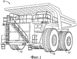
[0009] Фиг.1 представляет собой вид в аксонометрии ВТС.[0009] Figure 1 is a perspective view of a PTS.
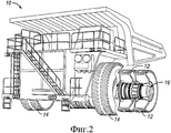
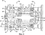
[0010] Фиг.2 представляет собой вид в разрезе частично в аксонометрии, изображающий колесный приводной узел ВТС, показанного на Фиг.1.[0010] FIG. 2 is a sectional view, partially in perspective, showing the wheel drive assembly of the PTS shown in FIG. 1.
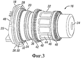
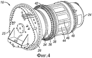
[0011] Фиг.3 и 4 представляют собой частичные виды сбоку и с торца в аксонометрии колесного приводного узла, показанного на Фиг.2.[0011] FIGS. 3 and 4 are partial side and side views in a perspective view of the wheel drive assembly shown in FIG. 2.
[0012] Фиг.5 представляет собой вид сбоку в разрезе колесного приводного узла, показанного на Фиг.2-4, содержащего и изображающего ободы для колеса, передачи и тормозной механизм, в соответствии с вариантом выполнения настоящего изобретения.[0012] FIG. 5 is a cross-sectional side view of the wheel drive assembly shown in FIGS. 2-4, comprising and depicting rims for a wheel, gear, and brake mechanism, in accordance with an embodiment of the present invention.
[0013] Фиг.6 представляет собой вид сбоку в разрезе колесного приводного узла и ободов колес, показанных на Фиг.5.[0013] FIG. 6 is a sectional side view of a wheel drive assembly and wheel rims shown in FIG. 5.
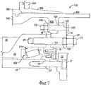
[0014] Фиг.7 представляет собой частичный увеличенный вид колесного приводного узла и ободов колес, показанных на Фиг.6.[0014] FIG. 7 is a partial enlarged view of a wheel drive assembly and wheel rims shown in FIG. 6.
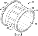
[0015] Фиг.8 представляет собой вид в аксонометрии наружной концевой части цельной ступицы, показанной на Фиг.6.[0015] FIG. 8 is a perspective view of the outer end portion of the integral hub shown in FIG. 6.
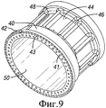
[0016] Фиг.9 представляет собой вид в аксонометрии внутренней концевой части цельной ступицы, показанной на Фиг.6.[0016] FIG. 9 is a perspective view of the inner end portion of the integral hub shown in FIG. 6.
ПОДРОБНОЕ ОПИСАНИЕ ИЗОБРЕТЕНИЯDETAILED DESCRIPTION OF THE INVENTION
[0017] Далее ссылка будет сделана подробно на иллюстративные варианты выполнения настоящего изобретения, примеры которых проиллюстрированы на прилагаемых чертежах. Везде, где возможно, одинаковые номера позиций, используемые на чертежах, относятся к одинаковым или подобным частям.[0017] Reference will now be made in detail to illustrative embodiments of the present invention, examples of which are illustrated in the accompanying drawings. Wherever possible, the same reference numbers used in the drawings refer to the same or similar parts.
[0018] В некоторых вариантах выполнения изобретения ободы колес, являющиеся объектом изобретения, выполнены с возможностью использования с ВТС 10, изображенном на Фиг.1 и 2. Как показано, ВТС 10 опирается на спаренные узлы 12 ободов задних сдвоенных ведущих колес и на узлы 14 ободов передних одинарных управляющих колес. Каждая пара узлов 12 шины/обода задних колес установлена на колесном узле 16. В различных вариантах выполнения каждый узел 12 шины может иметь радиус качения между приблизительно 1,6 м (м) и 1,8 м.[0018] In some embodiments of the invention, the wheel rims that are the subject of the invention are adapted to be used with the
[0019] Как показано на Фиг.3 и 4, каждый колесный узел 16 также содержит колесную несущую систему 18 и трубу 20, передающую крутящий момент. Труба 20 прикреплена к колесной ступице 22 с помощью болтов или шпилек. Узлы 12 обода также могут быть прикреплены к ступице 22 с помощью резьбовых крепежных элементов, как дополнительно обсуждается ниже. Труба 20, передающая крутящий момент, и ступица 22 установлены с возможностью вращения вокруг колесной несущей системы 18. В осевом направлении вблизи ступицы 22 к колесной несущей системе 18 жестко прикреплен тормозной узел или тормозной механизм 24, который, как обсуждается ниже, функционально соединен с трубой 20 и ступицей 22 через общий вал, расположенный внутри колесной несущей системы 18. Вблизи другой концевой части общего вала, напротив тормозного устройства 24, на колесной несущей системе 18 установлена крышка 25 коробки передач.[0019] As shown in FIGS. 3 and 4, each
[0020] Каждый колесный узел 16 может быть прикреплен к осевой втулке транспортного средства 10 посредством крепежного фланца 26, установленного на колесной несущей системе 18. Колесная несущая система 18 сужается на конус в радиальном направлении от установочного фланца 26, через в целом коническую или гиперболическую переходную часть 28, к цилиндрической или в целом цилиндрической втулке 52 колесной несущей системы (показана на Фиг.5). Маслоуплотнительное кольцо 30 закреплено на переходной части 28 колесной несущей системы 18. Термин «в целом», как он используется в настоящем описании, в связи с, например, признаками «конический», «гиперболический» и «цилиндрический», относится к этим общим формам и включает любые неровности или отклонения, следующие из обычной производственной практики, а также включает преднамеренно выполненные элементы, отклоняющиеся от общей формы. Например, в целом коническая или гиперболическая переходная часть 28 может содержать плоские участки, канавки, пазы, перфорации, отверстия и другие функциональные элементы, которые отличаются от идеальной конической или гиперболической формы.[0020] Each
[0021] Труба 20 является в целом цилиндрической и вблизи маслоуплотнительного кольца 30 содержит кольцевое зубчатое колесо 34. Труба 20 содержит трубчатую втулку 36, которая проходит от кольцевого зубчатого колеса 34 вдоль колесной несущей системы к фланцу 38 со стороны ступицы. На концевой части кольцевого зубчатого колеса 34, вблизи маслоуплотнительного кольца 30, к трубе 20 прикреплено дополняющее роторное уплотнение 32.[0021] The
[0022] Ступица 22 также является в целом цилиндрической и содержит втулку 44 с ребрами 46 (Фиг.6-9). Втулка 44 ступицы и ребра 46 проходят от первой радиально расширяющейся части у первой концевой части 40 до второй радиально расширяющейся части у второй концевой части 48. Втулка 44 окружает внутренний объем или внутреннюю полость 50, открытую на концевой части втулки. Ступица 22 также содержит периферийный фланец 42, который проходит в радиальном наружном направлении вокруг первой концевой части 40 ступицы.[0022] The
[0023] Фиг.5 представляет собой вид сбоку в разрезе, иллюстрирующий рабочие элементы колесного узла 16, выполненного в соответствии с вариантом выполнения настоящего изобретения. В колесном узле 16 первая концевая часть 40 ступицы 22 расположена внутри от второй концевой части 48 ступицы 22 или ближе к установочному фланцу 26 колесной несущей системы 18. Фланец 38 трубы 20 со стороны ступицы прикреплен к первой концевой части 40 ступицы 22. Внутренний узел 12a обода для колеса прикреплен к фланцу 42 ступицы 22 вблизи первой концевой части 40. Наружный узел 12a обода для колеса установлен на переходнике 72 ступицы, который закреплен на наружной, или второй, концевой части 48 ступицы 22. На первой и второй концевых частях 40, 48 ступицы 22 предусмотрены, соответственно, внутренний и наружный подшипники 51a, 51b, проходящие радиально вовнутрь от аксиально-внутреннего и наружного ободов 12a, 12b для поддержки ступицы на втулке 52 колесной несущей системы.[0023] FIG. 5 is a sectional side view illustrating operational elements of a
[0024] Втулка 52 проходит от переходной части 28 до кольцевой торцевой поверхности 53 со стороны ступицы, на которой установлен тормозной узел 24. Вблизи торцевой поверхности 53 внутри колесной несущей системы 18 расположен тяговый электродвигатель, заключенный в кожух 54. В кожухе 54 электродвигателя расположены статор 56 и ротор 58. Из ротора 58 тягового электродвигателя в направлении первой концевой части вблизи установочного фланца 26 колесной несущей системы 18, а также в направлении второй концевой части внутри тормозного узла 24 проходит вал 60. В тормозном узле 24 ротор 62 тормоза установлен на второй концевой части вала 60. В переходной части 28 колесной несущей системы 18 вал 64 солнечной шестерни прикреплен шлицевым соединением к первой концевой части вала 60. Вал 64 солнечной шестерни поддерживает солнечную шестерню 66, размещенную по центру в крышке 25 коробки передач. Солнечная шестерня 66 находится в зацеплении с несколькими планетарными шестернями 68, установленными на общих осях с ведущими шестернями 70, которые находятся в зацеплении с внутренними зубцами кольцевого зубчатого колеса 34 трубы 20. Некоторые варианты выполнения настоящего изобретения содержат три планетарные шестерни 68 и три ведущие шестерни 70. Труба 20 удерживается между ведущими шестернями 70 и ступицей 22.[0024] The
[0025] Фиг.6 показывает вид сбоку в разрезе цельной колесной несущей системы 18, цельной ступицы 22, кожуха 54 и статора 56 тягового электродвигателя, переходника 72 ступицы и внутреннего и внешнего ободов 12a, 12b колесного узла 16. В вариантах выполнения настоящего изобретения колесная несущая система 18 и ступица 22 выполнены как цельные, или бесшовные, конструкции, например, в некоторых вариантах выполнения, как цельнолитые. Ступица 22 имеет резьбовые отверстия 41, которые нарезаны от первой концевой части 40 ко второй концевой части 48 и предназначены для винтового крепления трубы 20 к ступице 22. Более конкретно, в варианте выполнения, изображенном на Фиг.6, фланец 38 трубы 20 со стороны ступицы крепится к первой концевой части 40 ступицы с помощью болтов, проходящих через фланец 38 и завинченных в резьбовое отверстие 41. Путем прижимания трубы 20 к ступице 22 внутренний подшипник 51 размещается в кольцевой полости 80a для подшипника, образованной между втулкой 52 колесной несущей системы и расширяющейся первой концевой частью 40 ступицы 22. В некоторых вариантах выполнения резьбовые отверстия или отверстия 41 совмещены, по меньшей мере частично, в осевом направлении с периферийным фланцем 42.[0025] FIG. 6 shows a cross-sectional side view of an integral
[0026] Ступица 22 также имеет отверстия 43, которые проходят в осевом направлении через фланец 42 для прикрепления внутреннего обода 12a колеса. Отверстия 43 могут быть с резьбой или гладкими. В одном варианте выполнения отверстия 43 являются гладкими, выполненными с возможностью вставления в них рифленых концов рифленых шпилек 73. Ступица 22 также имеет резьбовые отверстия 49, которые имеют резьбу в осевом направлении от второй концевой части 48 к первой концевой части 40 для крепления переходника 72 ступицы. В одном варианте выполнения разнообразные отверстия 41, 43, 49 отстоят друг от друга в окружном направлении симметричным образом и взаимно не совмещены. Хотя крепление с помощью винтов узлов 12a, 12b обода на колесном узле 16 может быть выполнено в различных конфигурациях, в варианте выполнения, изображенном на Фиг.6, отверстия 43 и 49 поддерживают, соответственно, шпильки 73a, резьбовые концы которых проходят в целом в осевом направлении ко второй концевой части 48, и шпильки 74, которые проходят от второй концевой части 48.[0026] The
[0027] Со ссылкой на внутренний и наружный узлы 12a, 12b, каждый узел обода колеса прикреплен к ступице 22 посредством болтов или шпилек или других крепежных элементов 73a, 73b, которые проходят через разнообразные отверстия, выполненные в проходящем радиально внутрь диске, кромке или фланце 82a, 82b каждого узла 12a, 12b. Фланец 82a обода внутреннего узла 12a шины прижат к соседнему фланцу 42 ступицы путем затягивания гаек 84a на шпильках 73a. Аналогично, фланец 82b обода наружного узла 12b прижат к переходнику 72 ступицы путем затягивания гаек 84b на шпильках 73b.[0027] With reference to the inner and
[0028] Со ссылкой на иллюстративный наружный узел 12b обода, внутренняя круговая кромка или фланец 82b обода выполнен как одно целое с по существу цилиндрическим корпусом колеса или ободом 86b колеса, который окружает открытое внутреннее пространство 87b. Обод 86b расположен на радиусе между (и включая) приблизительно 0,6 м и приблизительно 0,9 м от соответствующей оси колеса. На первой концевой части обода 86b первый торцевой фланец 88b прижат к коническому расширяющемуся наружу уступу 90b, выполненному как часть обода 86b. Напротив первого торцевого фланца 88b второй торцевой фланец или обод 92b с возможностью снятия расклиниванием закреплен на утолщенной части 94b обода 86b с помощью одного или нескольких расклинивающих колец 96b обода, которые удерживаются на месте с помощью стопорного кольца 98b.[0028] With reference to an illustrative
[0029] Предпочтительно, в некоторых вариантах выполнения изобретения фланец 82b обода может быть расположен ближе ко второму торцевому фланцу 92b, чем к первому торцевому фланцу 88b. В отдельных вариантах выполнения изобретения размещение фланца 82b обода ближе к выполненному с возможностью снятия расклиненному второму торцевому фланцу может обеспечить более эффективную, с точки зрения временных затрат, разборку и ремонт узла 12b шины.[0029] Preferably, in some embodiments, the
[0030] В вариантах выполнения настоящего изобретения внутренний узел 12a шины по существу идентичен наружному узлу 12b шины, а выполнение переходника 72 ступицы и смещенных в осевом направлении фланцев 82a, 82b обода обеспечивает возможность взаимозаменяемого крепления двух узлов 12a, 12b шины к ступице 22. Например, размещение фланца 82 обода с осевым смещением от осевой средней плоскости обода 86 может обеспечить возможность функционального соединения относительно широких в осевом направлении узлов 12a, 12b обода с колесным приводным узлом 16 с использованием относительно узкой в осевом направлении ступицы 22. Это может быть достигнуто путем установки внутреннего узла 12a шины в первой ориентации, когда его первый торцевой фланец 88 обращен вовнутрь, а затем установки переходника 72 ступицы на ступицу 22 с прикрепленным к переходнику 72 ступицы наружным узлом 12b шины во второй ориентации, когда его первый торцевой фланец 88 обращен наружу, как в иллюстративном варианте выполнения, показанном на Фиг.6 и 7. Использование переходника 72 ступицы для установки на относительно узкую в осевом направлении ступицу 22 двух относительно широких в осевом направлении узлов 12a, 12b обода может обеспечить меньший вес колесного приводного узла с превосходной максимальной допустимой нагрузкой.[0030] In embodiments of the present invention, the
[0031] Со ссылкой конкретно на Фиг.7, переходник 72 имеет по существу кольцевой корпус 100, через который в осевом направлении проходят несколько отверстий 101. Отверстия 101 являются гладкими для обеспечения зазора вокруг резьбовых шпилек 74. Переходник 72 прикреплен к цельной ступице 22 с помощью гаек 85, навинченных на шпильки 74. Переходник 72 также содержит кольцевой периферийный уступ 102, который проходит в радиальном наружном направлении вокруг осевой части кольцевого пространства 100. Периферийный уступ 102 имеет несколько отверстий 103, в которые вставлены соответствующие несколько шпилек 73. Путем навинчивания гаек 84b на шпильки 73b, периферийный внутренний фланец 82b наружного узла 12b обода прижимается к первой поверхности 104 уступа 102. Как показано, первая поверхность 104 уступа обращена «вовнутрь» вдоль направления, проходящего от второй концевой части ступицы к первой концевой части ступицы, и от торцевой поверхности колесной несущей системы со стороны ступицы в направлении установочного фланца колесной несущей системы. В изображенном варианте выполнения расположение обода 12b колеса и переходника 72 относительно ступицы 22 облегчает установку обода 12b на ступицу 22 и удаление обода 12b со ступицы 22.[0031] Referring specifically to FIG. 7, the
[0032] Между переходником 72 и ступицей 22 с помощью болтов уступа зафиксировано наружное маслоудерживающее кольцо 76. В радиальном внутреннем направлении от переходника 72 установочное кольцо 75 тормозного устройства прикреплено к концевой части 53 колесной несущей системы со стороны ступицы с помощью нескольких болтов 77 уступа. Установочное кольцо 75 зафиксировано на колесной несущей системе 18 кожуха двигателя (показан на Фиг.5), а внутреннее маслоудерживающее кольцо 78 зафиксировано болтами 77 уступа между кожухом двигателя и концевой частью 53 колесной несущей системы со стороны ступицы. Маслоудерживающие кольца обеспечивают простое уплотнение шарнирного соединения для удержания твердой или жидкой смазки внутри наружного пространства 80b для подшипника, образованного между расширяющейся второй концевой частью 48 ступицы 22 и втулкой 52 колесной несущей системы для размещения наружного подшипника 51b. Как обсуждалось выше, расширяющаяся первая концевая часть 40 ступицы 22 ограничивает по существу аналогичное внутреннее пространство 80a подшипника вблизи фланца 38 трубы 20 со стороны ступицы.[0032] An outer oil-retaining
[0033] Со ссылкой на Фиг.8 и 9, втулка 44 и ребра 46 цельной ступицы 22 проходят от первой концевой части 40 до второй концевой части 48. Втулка 44 имеет внутренний диаметр, выбранный с малым зазором (без помех и без скольжения), описанный вокруг втулки 52 колесной несущей системы. Обращенная в радиальном внутреннем направлении поверхность первой концевой части 40 расходится в наружном направлении от внутреннего диаметра втулки 44, чтобы обеспечить кольцевое внутреннее пространства 80a для подшипника для размещения внутреннего подшипника 51a, как обсуждалось выше со ссылкой на Фиг.5. Аналогичным образом, обращенная в радиальном внутреннем направлении поверхность второй концевой части 48 также расходится в наружном направлении, чтобы обеспечить кольцевое внутреннее пространства 80b для подшипника для размещения наружного подшипника 51b, как было описано выше со ссылкой на Фиг.5 и 6.[0033] With reference to FIGS. 8 and 9, the
[0034] Для снижения веса толщина втулки 44 ступицы снижена так, что проходящие в радиальном направлении ребра 46 передают значительную часть скручивающих и изгибающих нагрузок между внутренними и внешними концевыми частями 40, 48. В некоторых вариантах выполнения ребра 46 передают большую часть скручивающих нагрузок и большую часть изгибающих нагрузок. В отдельных вариантах выполнения ребра 46 передают более чем приблизительно 75% скручивающих и изгибающих нагрузок между внутренними и внешними концевыми частями 40, 48. В отдельных вариантах выполнения сниженная толщина втулки 44 может обеспечить возможность поддержания веса цельной ступицы 22 в пределах максимально предусмотренного веса, одновременно преимущественно обеспечивая радиальное утолщение концевых частей 40, 48 ступицы, для размещения тяжелых болтов или шпилек 73, 74. Например, в некоторых вариантах выполнения могут быть использованы болты класса SAE 8, чтобы обеспечить большую прочность и долговечность крепления шинного узла, чем может быть получено с использованием легких крепежных средств, таких как клинья и стопорные кольца. Использование проходящих в осевом направлении резьбовых крепежных деталей может преимущественно обеспечивать быстрое и хорошо контролируемое крепление узлов 12a, 12b обода к колесному узлу 16 и их удаление с колесного узла 16.[0034] To reduce weight, the thickness of the
[0035] В одном варианте выполнения и со ссылкой на Фиг.6 и 7, в качестве этапа крепления внутреннего обода 12a на ВТС 10 могут быть использованы гайки 84а для крепления внутреннего обода 12a на болтах или шпильках 73a, которые вставлены в отверстия 43 фланца 42 ступицы 22 и проходят по существу в наружном направлении от фланца 42. Затем внутренний обод 12b может быть прикреплен к ВТС 10, сначала используя болты или шпильки 73b и гайки 84b для крепления внутреннего обода 12b к переходнику 72, а затем путем крепления переходника 72 с помощью гаек 85 на шпильки или болты 74, установленные и проходящие из второй концевой части 48 ступицы 22.[0035] In one embodiment, and with reference to FIGS. 6 and 7, nuts 84a can be used as a step for attaching the
[0036] Варианты выполнения колесных ободов 12a, 12b и колесного узла 16, в соответствии с изобретением, могут выдерживать нагрузки сверх пятидесяти тонн в направлении, перпендикулярном оси колеса. В отдельных вариантах выполнения изобретения колесный узел 16 может выдерживать нагрузки, превышающие сто тонн в направлении, перпендикулярном оси колеса. В некоторых вариантах выполнения изобретения колесный узел 16 может выдерживать нагрузки, превышающие сто тридцать тонн в направлении, перпендикулярном оси колеса.[0036] Embodiments of the
[0037] В одном варианте выполнения изобретения колесный узел для внедорожного транспортного средства содержит в целом цилиндрическую колесную ступицу, которая проходит в осевом направлении от первой концевой части до второй концевой части вокруг внутреннего объема. Ко второй концевой части ступицы прикреплен переходник, который имеет периферийный уступ, имеющий поверхность, обращенную в осевом направлении к первой концевой части ступицы. Обод первого колеса, или первый обод, прикреплен к периферийному уступу переходника ступицы на поверхности, обращенной в осевом направлении к первой концевой части ступицы. В некоторых вариантах выполнения обод первого колеса окружает по окружности открытую внутреннюю часть и проходит в осевом направлении от первой концевой части фланца ко второй концевой части фланца, и закреплен на переходнике ступицы посредством проходящего по окружности внутреннего фланца обода, который расположен ближе ко второй концевой части фланца, чем к первой концевой части фланца внутри открытой внутренней части обода колеса. Открытая внутренняя часть обода первого колеса может быть выполнена с возможностью размещения в нем тормозного механизма. Колесный узел может дополнительно содержать в целом цилиндрическую колесную несущую систему, которая ограничивает ось колеса и проходит вдоль оси колеса от установочного фланца до концевой части со стороны ступицы. В отдельных вариантах выполнения в целом цилиндрическая труба, передающая крутящий момент, может быть установлена вокруг колесной несущей системы и соосно с ней. Такая труба может проходить от кольцевого зубчатого колеса, расположенного вблизи установочного фланца колесной несущей системы, до фланца со стороны ступицы, расположенного рядом с концевой частью колесной несущей системы со стороны ступицы. В отдельных вариантах выполнения первая концевая часть ступицы может быть прикреплена к фланцу трубы, передающей крутящий момент, со стороны ступицы, а вторая концевая часть ступицы может быть расположена рядом с концевой частью колесной несущей системы со стороны ступицы. В конкретных вариантах выполнения вторая концевая часть ступицы может быть расположена по существу в одной плоскости с концевой частью колесной несущей системы со стороны ступицы, так что вторая концевая часть ступицы и концевая часть колесной несущей системы со стороны ступицы вместе образуют кольцевое пространство для размещения наружного подшипника.[0037] In one embodiment, the wheel assembly for an off-road vehicle comprises a generally cylindrical wheel hub that extends axially from a first end portion to a second end portion around an inner volume. An adapter is attached to the second end part of the hub, which has a peripheral ledge having an axially facing surface to the first end part of the hub. The rim of the first wheel, or the first rim, is attached to the peripheral ledge of the hub adapter on the surface axially facing the first end of the hub. In some embodiments, the rim of the first wheel surrounds the circumference of the open inner part and extends axially from the first end part of the flange to the second end part of the flange, and is fixed to the hub adapter through the circumference of the inner flange of the rim, which is closer to the second end part of the flange than to the first end of the flange inside the open inner part of the wheel rim. The open inner part of the rim of the first wheel can be made with the possibility of placing a brake mechanism in it. The wheel assembly may further comprise a generally cylindrical wheel bearing system that defines the wheel axis and extends along the wheel axis from the mounting flange to the end portion from the hub side. In certain embodiments, a generally cylindrical torque-transmitting pipe can be mounted around and aligned with the wheel carrier system. Such a pipe may extend from an annular gear located near the mounting flange of the wheel carrier system to a flange on the hub side located near the end portion of the wheel carrier system on the hub side. In certain embodiments, the first end portion of the hub can be attached to the flange of the torque-transmitting pipe on the hub side, and the second end portion of the hub can be located adjacent to the end portion of the wheel carrier system on the hub side. In specific embodiments, the second end part of the hub can be substantially in the same plane as the end part of the wheel bearing system on the hub side, so that the second end part of the hub and the end part of the wheel bearing system on the hub side together form an annular space for accommodating the outer bearing.
[0038] В одном варианте выполнения установочный фланец колесной несущей системы может быть прикреплен болтами к внедорожному транспортному средству. В отдельных вариантах выполнения колесный узел на установочном фланце колесной несущей системы и на ступице способен поддерживать по меньшей мере приблизительно пятьдесят тонн в направлении, перпендикулярном оси колеса.[0038] In one embodiment, the mounting flange of the wheel carrier system may be bolted to an off-road vehicle. In certain embodiments, the wheel assembly on the mounting flange of the wheel carrier system and on the hub is capable of supporting at least about fifty tons in a direction perpendicular to the axis of the wheel.
[0039] В одном варианте выполнения ступица колесного узла может содержать цилиндрическую или по существу цилиндрическую втулку, ограничивающую ось ступицы и проходящую вдоль оси ступицы от первой концевой части ко второй концевой части. Втулка ступицы на первой концевой части может иметь первую расширяющуюся часть, которая имеет первое множество резьбовых отверстий, проходящих в осевом направлении в первой расширяющейся части в направлении втулки. Фланец трубы, передающей крутящий момент, со стороны ступицы может быть привинчен болтами с помощью первого множества резьбовых отверстий. Периферийный фланец ступицы может проходить в радиальном наружном направлении от осевой части первой расширяющейся части. На второй концевой части втулки ступицы вторая расширяющаяся часть может иметь второе множество резьбовых отверстий, проходящих в осевом направлении во второй расширяющейся части к втулке ступицы. Переходник ступицы может быть привинчен болтами с помощью второго множества резьбовых отверстий, выполненных во второй расширяющейся части. Такая ступица может быть установлена на колесную несущую систему так, что ось ступицы соосна оси колеса.[0039] In one embodiment, the hub of the wheel assembly may comprise a cylindrical or substantially cylindrical hub defining the axis of the hub and extending along the axis of the hub from the first end portion to the second end portion. The hub sleeve at the first end portion may have a first expanding portion that has a first plurality of threaded holes extending axially in a first expanding portion in the direction of the hub. The flange of the torque-transmitting pipe on the hub side can be bolted with a first set of threaded holes. The peripheral flange of the hub can extend radially outward from the axial portion of the first expanding portion. At the second end portion of the hub sleeve, the second expanding portion may have a second plurality of threaded holes extending axially in the second expanding portion toward the hub hub. The hub adapter can be bolted with a second set of threaded holes made in the second expanding part. Such a hub can be mounted on a wheel carrier system so that the axis of the hub is aligned with the axis of the wheel.
[0040] В одном варианте выполнения колесный узел может дополнительно содержать двигатель, установленный в концевой части колесной несущей системы со стороны ступицы. Вал двигателя может проходить в первом направлении вдоль оси колеса к установочному фланцу колесной несущей системы и может быть функционально соединен с планетарной передачей, расположенной в установочном фланце колесной несущей системы и включающей солнечную шестерню, функционально соединенную с валом двигателя, несколько планетарных шестерен, взаимодействующих с солнечной шестерней, и несколько ведущих шестерен, каждая из которых установлена на приводном валу, проходящем от одной из планетарных шестерен к концевой части колесной несущей системы со стороны ступицы. Каждая ведущая шестерня может взаимодействовать с кольцевым зубчатым колесом трубы, передающей крутящий момент, через отверстие для ведущей шестерни, проходящее через колесную несущую систему. В некоторых вариантах выполнения вал двигателя может также проходить во втором направлении вдоль оси колеса к концевой части, на которой расположен ротор, который выполнен с возможностью функционального взаимодействия с тормозным механизмом, установленным на концевой части колесной несущей системы со стороны ступицы.[0040] In one embodiment, the wheel assembly may further comprise an engine mounted in the end portion of the wheel carrier system from the hub side. The engine shaft can extend in the first direction along the axis of the wheel to the mounting flange of the wheel carrier system and can be functionally connected to a planetary gear located in the mounting flange of the wheel carrier system and including the sun gear, functionally connected to the motor shaft, several planet gears interacting with the sun gear, and several driving gears, each of which is mounted on a drive shaft passing from one of the planetary gears to the end of the wheel carrier system from the hub. Each pinion gear can interact with the ring gear of the torque transmitting pipe through a pinion hole extending through the wheel carrier system. In some embodiments, the engine shaft may also extend in a second direction along the axis of the wheel to the end portion on which the rotor is located, which is configured to interact with the braking mechanism mounted on the end portion of the wheel carrier system from the hub side.
[0041] В одном варианте выполнения первый обод может быть прикреплен к переходнику ступицы с помощью первого множества проходящих в осевом направлении шпилек, расположенных снаружи в радиальном наружном направлении от второго множества проходящих в осевом направлении шпилек, которые крепят переходник к ступице. Ступица может дополнительно содержать проходящий в радиальном наружном направлении периферийный фланец, выполненный вблизи первой концевой части ступицы. Периферийный фланец ступицы может иметь поверхность, обращенную ко второй концевой части ступицы, а обод второго колеса, или второй обод, может быть прикреплен к периферийному фланцу на поверхности, обращенной ко второй концевой части ступицы. Второй обод может быть установлен на ступице так, что его внутренний окружный фланец расположен между периферийным фланцем ступицы и второй концевой частью ступицы. Обод второго колеса может быть по существу идентичен ободу первого колеса.[0041] In one embodiment, the first rim may be attached to the hub adapter using a first plurality of axially extending studs located externally in a radially outward direction from a second plurality of axially extending studs that attach the adapter to the hub. The hub may further comprise a peripheral flange extending radially outwardly near the first end portion of the hub. The peripheral flange of the hub may have a surface facing the second end portion of the hub, and the rim of the second wheel, or the second rim, may be attached to the peripheral flange on the surface facing the second end of the hub. The second rim can be mounted on the hub so that its inner circumferential flange is located between the peripheral flange of the hub and the second end part of the hub. The rim of the second wheel may be substantially identical to the rim of the first wheel.
[0042] В одном варианте выполнения ступица может представлять собой цельное отлитое изделие или отливку. Термин «отливка», используемый в настоящем документе, относится к производственному процессу, при котором жидкий материал подают в форму или в полость, имеющую форму требуемого изделия, и дают ему возможность там затвердеть. «Отливка» также может относиться к затвердевшему изделию, которое вынимают или выламывают из формы по завершении процесса отливки.[0042] In one embodiment, the hub may be a solid molded product or cast. The term "casting" as used herein refers to a manufacturing process in which a liquid material is fed into a mold or cavity having the shape of a desired article and allowed to solidify there. "Casting" may also refer to a hardened product that is removed or broken out of the mold upon completion of the casting process.
[0043] В другом варианте выполнения первый обод колеса прикреплен к ступице путем вставления первого множества резьбовых крепежных элементов в отверстия, выполненные на внутреннем периферийном фланце первого обода колеса, и в соответствующее множество отверстий, выполненных в периферийном фланце, предусмотренном на первой концевой части ступицы. Второй обод установлен на переходнике ступицы путем вставления второго множества резьбовых крепежных элементов в отверстия, выполненные на внутреннем периферийном фланце обода второго колеса, и в соответствующее множество отверстий, выполненных в периферийном уступе переходника ступицы. Переходник ступицы прикреплен ко второй концевой части ступицы, причем фланец обода второго колеса размещают в осевом направлении между периферийным уступом переходника ступицы и ободом первого колеса путем вставления третьего множества резьбовых крепежных элементов в множество отверстий, выполненных в кольцевом корпусе переходника ступицы, и в соответствующее множество отверстий, выполненных во второй концевой части ступицы.[0043] In another embodiment, the first wheel rim is attached to the hub by inserting the first plurality of threaded fasteners into holes made on the inner peripheral flange of the first wheel rim and into a corresponding plurality of holes made in the peripheral flange provided on the first end portion of the hub. The second rim is mounted on the hub adapter by inserting the second plurality of threaded fasteners into the holes made on the inner peripheral flange of the second wheel rim and into the corresponding plurality of holes made in the peripheral ledge of the hub adapter. The hub adapter is attached to the second end part of the hub, the flange of the rim of the second wheel being axially positioned between the peripheral step of the hub adapter and the rim of the first wheel by inserting a third set of threaded fasteners into the plurality of holes made in the annular housing of the hub adapter and into the corresponding plurality of holes made in the second end part of the hub.
[0044] В одном варианте выполнения изобретения колесный узел для внедорожного транспортного средства содержит по существу цилиндрическую ступицу для колеса и кольцевой переходник, который прикреплен к указанной ступице. Ступица проходит в осевом направлении от первой концевой части до второй концевой части вокруг внутреннего объема. Вторая концевая часть ступицы ограничивает кольцевую торцевую поверхность, в целом перпендикулярную продольной оси ступицы. К кольцевой торцевой поверхности второй концевой части ступицы прикреплен к с возможностью отсоединения кольцевой переходник ступицы. Переходник содержит кольцевой корпус, проходящий в осевом наружном направлении от кольцевой торцевой поверхности ступицы, и кольцевой периферийный уступ, выполненный как единое целое с кольцевым корпусом переходника и проходящий от него в радиальном наружном направлении. Кольцевой периферийный уступ переходника ступицы имеет первую поверхность, обращенную в направлении, проходящем от второй концевой части к первой концевой части ступицы. Первая поверхность уступа в целом параллельна кольцевой торцевой поверхности второй концевой части ступицы, но смещена относительно нее в радиальном и в осевом направлениях. Кольцевой периферийный уступ также имеет вторую поверхность, обращенную в направлении, проходящем от первой концевой части ко второй концевой части ступицы. Вторая поверхность уступа в целом параллельна первой поверхности уступа и может быть в целом копланарна торцевой поверхности корпуса переходника ступицы. Кольцевой периферийный уступ ограничивает несколько разнесенных друг от друга отверстий, каждое из которых проходит через кольцевой периферийный уступ от его первой поверхности до его второй поверхности. Каждое из этих отверстий образует продольную ось, по существу параллельную продольной оси ступицы. Ступица и переходник выполнены с возможностью установки обода колеса на первую поверхность периферийного уступа кольцевого переходника путем соответствующего пропускания нескольких болтов или других крепежных элементов через указанное множество разнесенных друг от друга отверстий и через соответствующим образом расположенные отверстия, предусмотренные в ободе колеса.[0044] In one embodiment, the wheel assembly for an off-road vehicle comprises a substantially cylindrical wheel hub and an annular adapter that is attached to said hub. The hub extends axially from the first end portion to the second end portion around the inner volume. The second end part of the hub defines an annular end surface that is generally perpendicular to the longitudinal axis of the hub. To the annular end surface of the second end part of the hub is attached to a removable annular hub adapter. The adapter comprises an annular housing extending axially outward from the annular end surface of the hub and an annular peripheral ledge integrally with the annular housing of the adapter and extending radially outward from it. The annular peripheral ledge of the hub adapter has a first surface facing in a direction extending from the second end portion to the first end portion of the hub. The first surface of the ledge is generally parallel to the annular end surface of the second end part of the hub, but is offset relative to it in the radial and axial directions. The annular peripheral ledge also has a second surface facing in a direction extending from the first end part to the second end part of the hub. The second surface of the ledge is generally parallel to the first surface of the ledge and can be generally coplanar to the end surface of the hub adapter housing. An annular peripheral ledge restricts several openings spaced from each other, each of which passes through an annular peripheral ledge from its first surface to its second surface. Each of these holes forms a longitudinal axis substantially parallel to the longitudinal axis of the hub. The hub and the adapter are configured to mount the wheel rim on the first surface of the peripheral ledge of the ring adapter by appropriately passing several bolts or other fasteners through the specified set of spaced apart holes and through the correspondingly located holes provided in the wheel rim.
[0045] В одном варианте выполнения первая концевая часть ступицы может содержать первое множество отверстий, проходящих в осевом направлении в ступицу ко второй концевой части, а также может содержать в целом кольцевой периферийный фланец, проходящий вокруг части первой концевой части, по меньшей мере частично совпадающий в осевом направлении с первым множеством отверстий. Периферийный фланец может содержать второе множество отверстий, проходящих через периферийный фланец в местах, смещенных в радиальном направлении и по окружности от первого множества отверстий, и выполненных с возможностью крепления к ступице обода другого колеса. Колесный узел может дополнительно содержать колесную несущую систему, проходящую от установочного фланца к концевой части ступицы, при этом ступица установлена с возможностью вращения вокруг части колесной несущей системы, расположенной рядом с концевой частью ступицы. Колесный узел может также содержать в целом цилиндрическую трубу, передающую крутящий момент, установленную с возможностью вращения вокруг части колесной несущей системы между ступицей и установочным фланцем, причем указанная труба имеет по существу кольцевую первую концевую часть, расположенную вблизи установочного фланца, и имеет по существу кольцевую вторую концевую часть, жестко прикрепленную к ступице посредством крепежных элементов, вставляемых в первое множество отверстий в ступице и поддерживаемых ступицей. Установочный фланец колесной несущей системы может быть в целом кольцевым, а концевая часть колесной несущей системы со стороны ступицы в целом может быть кольцевой и меньшего диаметра, чем установочный фланец. В таком варианте выполнения установочный фланец может быть соединен как одно целое с концевой частью ступицы через в целом гиперболическую переходную часть вблизи установочного фланца и через по существу цилиндрическую втулку, проходящую от переходной части к концевой части ступицы. Переходная часть колесной несущей системы может иметь несколько отверстий для ведущей шестерни, а первая концевая часть трубы, передающей крутящий момент, может содержать зубчатую шестерню с обращенными вовнутрь зубцами, которая окружает отверстия для ведущей шестерни. В варианте выполнения, содержащем планетарную передачу, размещенную внутри переходной части колесной несущей системы и приводимой в действие электродвигателем, расположенным внутри втулки колесной несущей системы, планетарная передача может содержать ведущие шестерни, проходящие через отверстия для ведущих шестерен в колесной несущей системе, для взаимодействия с кольцевым зубчатым колесом трубы, передающей крутящий момент, и для ее радиальной поддержки.[0045] In one embodiment, the first end portion of the hub may comprise a first plurality of holes extending axially into the hub to the second end portion, and may also comprise a generally annular peripheral flange extending around the portion of the first end portion at least partially coinciding in the axial direction with the first set of holes. The peripheral flange may comprise a second plurality of holes passing through the peripheral flange in places radially and circumferentially offset from the first plurality of holes and configured to attach another wheel to the hub of the rim. The wheel assembly may further comprise a wheel bearing system extending from the mounting flange to the end portion of the hub, the hub being rotatably mounted around a portion of the wheel bearing system adjacent to the end portion of the hub. The wheel assembly may also comprise a generally cylindrical tube transmitting a torque mounted rotatably around a portion of the wheel support system between the hub and the mounting flange, said pipe having a substantially annular first end portion located adjacent to the mounting flange and has a substantially annular a second end portion rigidly attached to the hub by means of fasteners inserted into the first plurality of holes in the hub and supported by the hub. The mounting flange of the wheel bearing system may be generally annular, and the end portion of the wheel bearing system from the hub as a whole may be annular and smaller in diameter than the mounting flange. In such an embodiment, the mounting flange can be connected integrally with the end part of the hub through a generally hyperbolic transition part near the mounting flange and through a substantially cylindrical sleeve extending from the transition part to the end part of the hub. The transitional part of the wheel bearing system may have several openings for the pinion gear, and the first end part of the torque transmitting pipe may comprise a pinion gear with inwardly facing teeth that surrounds the holes for the pinion gear. In an embodiment comprising a planetary gear located inside the transitional part of the wheel bearing system and driven by an electric motor located inside the hub of the wheel bearing system, the planetary gear may include pinion gears passing through the holes for pinion gears in the wheel bearing system to interact with the ring a gear wheel of a pipe transmitting torque, and for its radial support.
[0046] Специалисту понятно, что приведенное выше описание является иллюстративным, а не ограничивающим. Например, вышеописанные варианты выполнения (и/или их аспекты) можно применять в сочетании друг с другом. Кроме того, возможно выполнение многочисленных модификаций, обусловленных конкретным обстоятельством или материалом без выхода за рамки объема изобретения. Хотя размеры и виды материалов, описанные в данном документе, предназначены для определения характеристик изобретения, они не являются ограничивающими и представляют собой иллюстративные варианты выполнения. Из приведенного выше описания специалисту будут понятны многие другие варианты выполнения. Таким образом, объем изобретения следует определять исходя из пунктов прилагаемой формулы изобретения, а также из полного объема эквивалентов, к которым указанные пункты относятся. В прилагаемой формуле изобретения выражения «включающий» и «в котором» используются в качестве эквивалентов соответствующих выражений «содержащий» и «причем». Кроме того, в приведенной ниже формуле изобретения выражения «первый», «второй», «третий», «выше», «ниже», «низ», «верх» и т.д. используются исключительно в качестве обозначения, при этом указанные выражения не предполагают количественных или позиционных требований к соответствующим им объектам. Более того, ограничения приведенной ниже формулы изобретения описаны не в формате «средство плюс функция» и не должны толковаться на основании 6 абзаца §112 раздела 35 Свода законов США, за исключением случаев, когда для данных ограничений формулы изобретения специально не использована фраза «предназначенный для» с последующим указанием об отсутствии функции у дополнительной конструкции.[0046] One skilled in the art will appreciate that the above description is illustrative and not limiting. For example, the above-described embodiments (and / or aspects thereof) can be used in combination with each other. In addition, it is possible to perform numerous modifications due to a specific circumstance or material without going beyond the scope of the invention. Although the dimensions and types of materials described herein are intended to characterize the invention, they are not limiting and represent illustrative embodiments. From the above description, the specialist will understand many other options for execution. Thus, the scope of the invention should be determined on the basis of the points of the attached claims, as well as from the full scope of equivalents to which these points relate. In the appended claims, the expressions “comprising” and “in which” are used as equivalents to the corresponding expressions “comprising” and “wherein”. In addition, in the following claims, the expressions “first”, “second”, “third”, “above”, “below”, “bottom”, “top”, etc. are used solely as a designation, while these expressions do not imply quantitative or positional requirements for their respective objects. Moreover, the limitations of the claims below are not described in the “tool plus function” format and should not be construed in accordance with paragraph 6 of Section 110 of Section 35 of the US Code, unless the phrase “specifically intended to »Followed by an indication of the lack of function of the additional design.
[0047] В данном описании использованы примеры для раскрытия нескольких вариантов выполнения изобретения, включающих наиболее предпочтительный вариант выполнения, которые позволяют специалисту реализовать изобретение на практике, включая создание и применение любых устройств или систем и осуществление любых предусмотренных способов. Объем правовой охраны изобретения определен формулой изобретения и может включать другие примеры, которые возникнут у специалиста. Эти другие варианты не выходят за рамки объема формулы изобретения, если они содержат конструктивные элементы, которые не отличаются от точной формулировки в формуле изобретения, или если они содержат эквивалентные конструктивные элементы, имеющие несущественные отличия от точных формулировок формулы изобретения.[0047] Examples are used in this description to disclose several embodiments of the invention, including the most preferred embodiment, which enable a person skilled in the art to put the invention into practice, including the creation and use of any devices or systems and the implementation of any methods provided. The scope of legal protection of the invention is defined by the claims and may include other examples that arise from a specialist. These other options are not beyond the scope of the claims if they contain structural elements that do not differ from the exact wording in the claims, or if they contain equivalent structural elements having insignificant differences from the exact wording of the claims.
[0048] Как описано в данном документе, следует понимать, что элемент или этап, упомянутый в единственном числе, не исключает множественное число указанных элементов или этапов, если такое исключение не указано явно. Более того, выражение «один вариант выполнения» данного изобретения не следует интерпретировать как исключающее наличие дополнительных вариантов выполнения, которые также содержат перечисленные признаки. Более того, если явно не указано иное, варианты выполнения, «содержащие», «включающие» или «имеющие» элемент или несколько элементов, обладающих конкретным свойством, могут включать дополнительные указанные элементы, не обладающие указанным свойством.[0048] As described herein, it should be understood that the element or step mentioned in the singular does not exclude the plural of these elements or steps, unless such an exception is explicitly indicated. Moreover, the expression “one embodiment” of the present invention should not be interpreted as excluding the presence of additional embodiments that also contain the listed features. Moreover, unless expressly indicated otherwise, embodiments “comprising”, “including” or “having” an element or several elements having a specific property may include additional specified elements that do not have the specified property.
[0049] Поскольку в вышеописанном ободе колеса, колесном узле и в способе сборки могут быть сделаны определенные изменения без отхода от сущности и объема изобретения, в настоящем документе подразумевается, что все предметы изобретения, приведенные выше в описании изобретения или изображенные на прилагаемых чертежах, следует интерпретировать исключительно как примеры, иллюстрирующие изобретательскую концепцию и не должны толковаться как ограничивающие настоящее изобретение.[0049] Since certain changes may be made to the wheel rim, wheel assembly, and assembly method without departing from the spirit and scope of the invention, it is understood herein that all of the objects of the invention described above in the description of the invention or depicted in the accompanying drawings should interpreted solely as examples illustrating the inventive concept and should not be construed as limiting the present invention.
Claims (19)
в целом цилиндрическую ступицу для колеса, проходящую в осевом направлении от первой концевой части до второй концевой части вокруг внутреннего объема,
переходник ступицы, закрепленный на второй концевой части ступицы и имеющий периферийный уступ, первая поверхность которого обращена в осевом направлении, проходящем от второй концевой части к первой концевой части,
обод первого колеса, установленный на первой поверхности периферийного уступа переходника ступицы,
в целом цилиндрическую колесную несущую систему, ограничивающую ось колеса и проходящую вдоль нее от установочного фланца к концевой части со стороны ступицы, и
в целом цилиндрическую трубу, передающую крутящий момент, установленную вокруг колесной несущей системы и соосно с ней, причем указанная труба проходит от кольцевого зубчатого колеса вблизи установочного фланца колесной несущей системы до фланца со стороны ступицы вблизи концевой части колесной несущей системы со стороны ступицы,
при этом первая концевая часть ступицы прикреплена болтами к фланцу указанной трубы со стороны ступицы, а вторая концевая часть ступицы расположена рядом с концевой частью колесной несущей системы со стороны ступицы.1. Wheel assembly for an off-road vehicle, comprising:
a generally cylindrical wheel hub extending axially from a first end portion to a second end portion around an inner volume,
a hub adapter mounted on the second end part of the hub and having a peripheral step, the first surface of which faces in an axial direction extending from the second end part to the first end part,
the rim of the first wheel mounted on the first surface of the peripheral ledge of the hub adapter,
a generally cylindrical wheel carrier system bounding the axis of the wheel and extending along it from the mounting flange to the end portion from the hub side, and
a generally cylindrical pipe transmitting a torque installed around and in alignment with the wheel carrier system, said pipe extending from the ring gear in the vicinity of the mounting flange of the wheel carrier system to the flange on the hub side near the end of the wheel carrier system on the hub side,
the first end part of the hub is bolted to the flange of the specified pipe from the hub side, and the second end part of the hub is located next to the end part of the wheel bearing system from the hub side.
цилиндрическую или, по существу, цилиндрическую втулку, ограничивающую ось ступицы и проходящую вдоль этой оси от первой концевой части ко второй концевой части,
первую расширяющуюся часть на первой концевой части втулки, имеющую первое множество резьбовых отверстий, проходящих в осевом направлении в первую расширяющуюся часть к втулке, причем фланец трубы, передающей крутящий момент, со стороны ступицы прикручен болтами, проходящими в первое множество резьбовых отверстий,
периферийный фланец, проходящий в радиальном наружном направлении от осевой части первой расширяющейся части, и
вторую расширяющуюся часть на второй концевой части втулки ступицы, имеющую второе множество резьбовых отверстий, проходящих в осевом направлении во вторую расширяющуюся часть к втулке ступицы, причем переходник ступицы прикручен болтами, проходящими во второе множество резьбовых отверстий во второй расширяющейся части,
при этом ступица установлена на колесной несущей системе так, что ось ступицы и ось колеса коаксиальны.8. Wheel assembly according to claim 1, in which the hub contains:
a cylindrical or essentially cylindrical sleeve defining the axis of the hub and extending along this axis from the first end part to the second end part,
a first expanding portion on a first end portion of a sleeve having a first plurality of threaded holes extending axially into a first expanding portion to a bush, the flange of the torque transmission pipe being bolted from the hub side by bolts extending into the first plurality of threaded holes,
a peripheral flange extending radially outward from the axial portion of the first expanding portion, and
a second expanding part on the second end part of the hub sleeve having a second plurality of threaded holes extending axially into the second expanding part to the hub bushing, the hub adapter being bolted into the second plurality of threaded holes in the second expanding part,
wherein the hub is mounted on the wheel carrier system so that the axis of the hub and the axis of the wheel are coaxial.
двигатель, установленный в концевой части колесной несущей системы со стороны ступицы и имеющий вал, который проходит в первом направлении вдоль оси колеса в направлении установочного фланца колесной несущей системы, и
планетарную зубчатую передачу, расположенную в установочном фланце колесной несущей системы и содержащую солнечную шестерню, функционально соединенную с валом двигателя, планетарные шестерни, взаимодействующие с солнечной шестерней, и ведущие шестерни, каждая из которых установлена на приводном валу, проходящем от одной из планетарных шестерен к концевой части колесной несущей системы со стороны ступицы, причем каждая ведущая шестерня взаимодействует с кольцевым зубчатым колесом трубы, передающей крутящий момент, через отверстие для ведущей шестерни, проходящее через колесную несущую систему.9. The wheel assembly according to claim 1, further comprising:
an engine installed in the end of the wheel carrier system from the hub side and having a shaft that extends in a first direction along the axis of the wheel in the direction of the mounting flange of the wheel carrier system, and
planetary gear located in the mounting flange of the wheel bearing system and containing a sun gear, functionally connected to the engine shaft, planetary gears interacting with the sun gear, and drive gears, each of which is mounted on the drive shaft passing from one of the planetary gears to the end parts of the wheel carrier system from the hub side, each drive gear interacting with the ring gear of the torque transmission pipe through an opening for the pinion passing through the wheel bearing system.
в целом цилиндрическую ступицу для колеса, проходящую в осевом направлении от первой концевой части до второй концевой части вокруг внутреннего объема,
переходник ступицы, закрепленный на второй концевой части ступицы и имеющий периферийный уступ, первая поверхность которого обращена в осевом направлении, проходящем от второй концевой части к первой концевой части, и
обод первого колеса, установленный на первой поверхности периферийного уступа переходника ступицы,
причем вблизи первой части ступица также содержит проходящий в радиальном наружном направлении периферийный фланец, поверхность которого обращена ко второй концевой части ступицы, причем к периферийному фланцу ступицы на поверхности, обращенной ко второй концевой части ступицы, прикреплен обод второго колеса или второй обод.13. Wheel assembly for an off-road vehicle, comprising:
a generally cylindrical wheel hub extending axially from a first end portion to a second end portion around an inner volume,
a hub adapter mounted on the second end part of the hub and having a peripheral step, the first surface of which is facing in an axial direction extending from the second end part to the first end part, and
the rim of the first wheel mounted on the first surface of the peripheral ledge of the hub adapter,
moreover, near the first part, the hub also contains a peripheral flange extending radially outwardly, the surface of which faces the second end part of the hub, and a rim of the second wheel or second rim is attached to the peripheral flange of the hub on the surface facing the second end of the hub.
в целом цилиндрическую ступицу для колеса, проходящую в осевом направлении от первой концевой части до второй концевой части вокруг внутреннего объема, причем вторая концевая часть ограничивает кольцевую торцевую поверхность, которая в целом перпендикулярна продольной оси ступицы, и
кольцевой переходник ступицы, прикрепленный с возможностью отсоединения к кольцевой торцевой поверхности второй концевой части ступицы,
причем кольцевой переходник содержит корпус, проходящий в осевом наружном направлении от кольцевой торцевой поверхности, и кольцевой периферийный уступ, выполненный как одно целое с указанным корпусом, при этом кольцевой периферийный уступ проходит в радиальном наружном направлении от корпуса кольцевого переходника,
причем кольцевой периферийный уступ имеет первую поверхность, обращенную в направлении, проходящем от второй концевой части к первой концевой части ступицы, причем первая поверхность уступа в целом параллельна кольцевой торцевой поверхности второй концевой части ступицы, но смещена относительно нее в радиальном и в осевом направлениях,
причем кольцевой периферийный уступ имеет вторую поверхность, обращенную в направлении, проходящем от первой концевой части ко второй концевой части ступицы, причем вторая поверхность уступа, по существу, параллельна его первой поверхности,
при этом кольцевой периферийный уступ ограничивает множество разнесенных друг от друга отверстий, каждое из которых проходит через кольцевой периферийный уступ от его первой поверхности к его второй поверхности, причем продольная ось каждого отверстия в целом параллельна продольной оси ступицы,
при этом ступица и кольцевой переходник выполнены с возможностью установки обода колеса на первой поверхности периферийного уступа кольцевого переходника ступицы путем соответствующего вставления болтов или других крепежных элементов через указанное множество разнесенных друг от друга отверстий и через соответствующим образом расположенные отверстия, имеющиеся в ободе колеса,
причем первая концевая часть ступицы содержит первое множество отверстий, выполненных в ступице в осевом направлении ко второй концевой части, и содержит, по существу, кольцевой периферийный фланец, проходящий вокруг части первой концевой части, совпадая в осевом направлении, по меньшей мере частично, с первым множеством отверстий, причем периферийный фланец имеет второе множество отверстий, проходящих через периферийный фланец в местах, смещенных от указанного первого множества отверстий в радиальном и в окружном направлениях.16. Wheel assembly for an off-road vehicle, comprising:
a generally cylindrical wheel hub extending axially from the first end portion to the second end portion around the inner volume, the second end portion defining an annular end surface that is generally perpendicular to the longitudinal axis of the hub, and
an annular hub adapter attached detachably to the annular end surface of the second end portion of the hub,
moreover, the annular adapter comprises a housing extending axially outward from the annular end surface, and an annular peripheral ledge integrally formed with the indicated housing, wherein the annular peripheral ledge extends radially outwardly from the annular adapter housing,
moreover, the annular peripheral ledge has a first surface facing in a direction extending from the second end part to the first end part of the hub, the first surface of the ledge as a whole parallel to the annular end surface of the second end part of the hub, but offset relative to it in radial and axial directions,
moreover, the annular peripheral ledge has a second surface facing in a direction extending from the first end part to the second end part of the hub, and the second surface of the ledge is essentially parallel to its first surface,
wherein the annular peripheral ledge limits a plurality of openings spaced from each other, each of which passes through the annular peripheral ledge from its first surface to its second surface, the longitudinal axis of each hole being generally parallel to the longitudinal axis of the hub,
wherein the hub and the annular adapter are configured to mount the wheel rim on the first surface of the peripheral ledge of the annular hub adapter by appropriately inserting bolts or other fasteners through the indicated plurality of openings spaced apart from each other and through the correspondingly located holes in the wheel rim,
moreover, the first end part of the hub contains the first set of holes made in the hub in the axial direction to the second end part, and contains essentially an annular peripheral flange extending around the part of the first end part, coinciding in the axial direction, at least partially, with the first a plurality of holes, the peripheral flange having a second plurality of holes extending through the peripheral flange at locations offset from said first plurality of holes in radial and circumferential directions.
колесную несущую систему, проходящую от установочного фланца к концевой части со стороны ступицы, причем ступица установлена с возможностью вращения вокруг части колесной несущей системы вблизи указанной концевой части со стороны ступицы, и
в целом цилиндрическую трубу, передающую крутящий момент, установленную с возможностью вращения вокруг части колесной несущей системы между ступицей и установочным фланцем, причем указанная труба имеет в целом кольцевую первую концевую часть, расположенную вблизи установочного фланца, и имеет в целом кольцевую вторую концевую часть, жестко прикрепленную к ступице с помощью крепежных элементов, вставляемых в указанное первое множество отверстий в ступице, и поддерживаемую на указанной ступице.17. Wheel assembly according to clause 16, further comprising:
a wheel support system extending from the mounting flange to the end portion from the hub side, the hub being mounted rotatably around a portion of the wheel support system near the specified end portion from the hub side, and
a generally cylindrical tube transmitting a torque mounted rotatably around a part of the wheel support system between the hub and the mounting flange, said pipe having a generally annular first end portion located near the mounting flange and has a generally annular second end portion, rigidly attached to the hub by means of fasteners inserted into said first plurality of holes in the hub and supported on said hub.
Applications Claiming Priority (3)
| Application Number | Priority Date | Filing Date | Title |
|---|---|---|---|
| US13/046,718 | 2011-03-12 | ||
| US13/046,718 US8747271B2 (en) | 2011-03-12 | 2011-03-12 | Wheel rim assembly and method |
| PCT/US2012/026905 WO2012125282A1 (en) | 2011-03-12 | 2012-02-28 | Wheel rim assembly and method |
Publications (2)
| Publication Number | Publication Date |
|---|---|
| RU2545242C1 true RU2545242C1 (en) | 2015-03-27 |
| RU2013139686A RU2013139686A (en) | 2015-04-20 |
Family
ID=45811619
Family Applications (1)
| Application Number | Title | Priority Date | Filing Date |
|---|---|---|---|
| RU2013139686/11A RU2545242C1 (en) | 2011-03-12 | 2012-02-28 | Wheel rim assembly and method of wheel assembly |
Country Status (6)
| Country | Link |
|---|---|
| US (1) | US8747271B2 (en) |
| JP (1) | JP6018593B2 (en) |
| CN (1) | CN103402787B (en) |
| AU (1) | AU2012229461B2 (en) |
| RU (1) | RU2545242C1 (en) |
| WO (1) | WO2012125282A1 (en) |
Families Citing this family (10)
| Publication number | Priority date | Publication date | Assignee | Title |
|---|---|---|---|---|
| US9796211B2 (en) * | 2012-12-04 | 2017-10-24 | Caterpillar Global Mining Llc | Adapter for mounting larger diameter rims |
| US20150108828A1 (en) * | 2013-10-21 | 2015-04-23 | Caterpillar Inc. | Method of remanufacturing a wheel housing |
| US9598141B1 (en) * | 2016-03-07 | 2017-03-21 | Future Motion, Inc. | Thermally enhanced hub motor |
| US10112680B2 (en) | 2016-03-07 | 2018-10-30 | Future Motion, Inc. | Thermally enhanced hub motor |
| JP6695305B2 (en) * | 2017-06-12 | 2020-05-20 | 日立建機株式会社 | Work vehicle running device |
| NL2019305B1 (en) * | 2017-07-20 | 2019-02-12 | E Traction Europe Bv | Dual tyre rim |
| US11446960B2 (en) * | 2019-08-27 | 2022-09-20 | Toyota Motor Engineering & Manufacturing North America, Inc. | Modular axle and motive wheel system for a vehicle |
| AU2020347229A1 (en) * | 2019-09-09 | 2021-12-23 | Crrc Qishuyan Institute Co., Ltd. | Wheel drive system |
| USD982629S1 (en) | 2021-02-26 | 2023-04-04 | Npc Robotics Corporation | Boltless unitary ring gear-flange body |
| US20220379658A1 (en) * | 2021-06-01 | 2022-12-01 | Arvinmeritor Technology, Llc | Axle assembly having a brake drum and method of assembly |
Citations (1)
| Publication number | Priority date | Publication date | Assignee | Title |
|---|---|---|---|---|
| US4873894A (en) * | 1988-10-31 | 1989-10-17 | Caterpillar Inc. | Balanced free-planet drive mechanism |
Family Cites Families (15)
| Publication number | Priority date | Publication date | Assignee | Title |
|---|---|---|---|---|
| US2386917A (en) | 1943-02-06 | 1945-10-16 | Ray F Thornton | Driving axle construction |
| US3042145A (en) | 1960-05-20 | 1962-07-03 | Rockwell Standard Co | Axle outer end |
| US3951481A (en) | 1975-04-18 | 1976-04-20 | Caterpillar Tractor Co. | Planetary reaction hub and bearing retainer |
| JP2523347B2 (en) * | 1988-03-15 | 1996-08-07 | 株式会社小松製作所 | End cover device for electrically driven vehicle wheels |
| DE4101222A1 (en) | 1990-01-17 | 1991-07-18 | Zahnradfabrik Friedrichshafen | Vehicle axle bearing system - has taper-roller bearings on different dia. partly overlapping in axial direction |
| JPH09136502A (en) * | 1995-11-10 | 1997-05-27 | Asahi Tec Corp | Automobile wheel mounting structure body |
| US6148941A (en) | 1998-04-30 | 2000-11-21 | Caterpillar Inc. | Wheel assembly for a ground-driven work machine and method for assembling the same |
| US6080077A (en) * | 1999-02-15 | 2000-06-27 | Igor Kamlukin | Planetary gear drive train |
| FR2808849B1 (en) * | 2000-05-11 | 2002-08-23 | Renault Vehicules Ind | WHEEL MOUNTING SYSTEM ON A BRIDGE OR AXLE OF A ROLLING VEHICLE |
| US6382381B1 (en) * | 2000-09-06 | 2002-05-07 | Shimano Inc. | Bicycle hub assembly |
| US6588538B2 (en) | 2001-07-12 | 2003-07-08 | Caterpillar Inc. | Wheel and final drive assembly for a ground driven work machine |
| JP4724075B2 (en) * | 2006-08-29 | 2011-07-13 | 本田技研工業株式会社 | Wheel rotation device |
| ITTO20060894A1 (en) * | 2006-12-15 | 2008-06-16 | Oto Melara Spa | MOTORIZED WHEEL FOR A MILITARY VEHICLE |
| US20090102275A1 (en) | 2007-10-22 | 2009-04-23 | General Electric Company | Wheel mounting assembly |
| US8544579B2 (en) | 2008-05-13 | 2013-10-01 | Caterpillar Inc. | Axle assembly for electric drive machine |
-
2011
- 2011-03-12 US US13/046,718 patent/US8747271B2/en active Active
-
2012
- 2012-02-28 WO PCT/US2012/026905 patent/WO2012125282A1/en active Application Filing
- 2012-02-28 RU RU2013139686/11A patent/RU2545242C1/en active
- 2012-02-28 AU AU2012229461A patent/AU2012229461B2/en active Active
- 2012-02-28 JP JP2013557755A patent/JP6018593B2/en active Active
- 2012-02-28 CN CN201280012998.6A patent/CN103402787B/en active Active
Patent Citations (1)
| Publication number | Priority date | Publication date | Assignee | Title |
|---|---|---|---|---|
| US4873894A (en) * | 1988-10-31 | 1989-10-17 | Caterpillar Inc. | Balanced free-planet drive mechanism |
Also Published As
| Publication number | Publication date |
|---|---|
| RU2013139686A (en) | 2015-04-20 |
| JP6018593B2 (en) | 2016-11-02 |
| AU2012229461A1 (en) | 2013-09-12 |
| CN103402787A (en) | 2013-11-20 |
| US20120231915A1 (en) | 2012-09-13 |
| WO2012125282A1 (en) | 2012-09-20 |
| CN103402787B (en) | 2016-01-20 |
| JP2014512295A (en) | 2014-05-22 |
| AU2012229461B2 (en) | 2014-12-04 |
| US8747271B2 (en) | 2014-06-10 |
Similar Documents
| Publication | Publication Date | Title |
|---|---|---|
| RU2545242C1 (en) | Wheel rim assembly and method of wheel assembly | |
| AU2012222103B2 (en) | Wheel frame, assembly and method | |
| EP1905633A1 (en) | Electric wheel-drive device | |
| EP2666654B1 (en) | In-wheel motor drive device | |
| US8746396B2 (en) | Wheel hub, assembly, and method | |
| US8678518B2 (en) | Wheel mounting assembly | |
| EP2712066A2 (en) | Axle assembly having an electric motor module | |
| US8763495B2 (en) | Torque tube, torque transfer apparatus and method | |
| US9205737B2 (en) | Seal body, apparatus and method | |
| US20130308889A1 (en) | Cylindrical roller bearing apparatus | |
| CN215861427U (en) | Wheel hub brake assembly | |
| AU2013101647A4 (en) | Wheel hub, assembly, and method | |
| EP2631513B1 (en) | Seal body, apparatus and method | |
| AU2012201063B2 (en) | Seal body, apparatus and method | |
| CN113580922A (en) | Hub driving integrated device |