RU2541663C1 - Small-size plant for preparing feed - Google Patents
Small-size plant for preparing feed Download PDFInfo
- Publication number
- RU2541663C1 RU2541663C1 RU2013147260/13A RU2013147260A RU2541663C1 RU 2541663 C1 RU2541663 C1 RU 2541663C1 RU 2013147260/13 A RU2013147260/13 A RU 2013147260/13A RU 2013147260 A RU2013147260 A RU 2013147260A RU 2541663 C1 RU2541663 C1 RU 2541663C1
- Authority
- RU
- Russia
- Prior art keywords
- sides
- smaller
- working chamber
- equilateral triangle
- triangle
- Prior art date
Links
- 230000015572 biosynthetic process Effects 0.000 claims abstract description 15
- 238000002360 preparation method Methods 0.000 claims description 14
- 238000005452 bending Methods 0.000 claims description 3
- 239000002245 particle Substances 0.000 abstract description 11
- 230000008859 change Effects 0.000 abstract description 4
- 230000004907 flux Effects 0.000 abstract description 2
- 239000000126 substance Substances 0.000 abstract 1
- 238000009434 installation Methods 0.000 description 5
- 230000006835 compression Effects 0.000 description 4
- 238000007906 compression Methods 0.000 description 4
- 230000003993 interaction Effects 0.000 description 4
- 238000000034 method Methods 0.000 description 4
- 230000008569 process Effects 0.000 description 3
- 238000003466 welding Methods 0.000 description 3
- 238000010586 diagram Methods 0.000 description 1
- 238000004519 manufacturing process Methods 0.000 description 1
- 238000005259 measurement Methods 0.000 description 1
- 230000003094 perturbing effect Effects 0.000 description 1
- 239000007787 solid Substances 0.000 description 1
- 230000000007 visual effect Effects 0.000 description 1
Images
Abstract
Description
Изобретение относится к устройствам для смешивания, в частности к смесителям непрерывного действия, предназначенным для смешивания концентрированных комбикормов.The invention relates to a mixing device, in particular to continuous mixers, designed to mix concentrated feed.
Известно устройство для смешивания кормов (патент №2372817, кл. A23N 17/00, 2006 г.), содержащее станину, установленный на ней посредством введенной в устройство рамы с пневмобаллонами с возможностью вращения барабан, состоящий из секций при этом боковая поверхность каждой секции барабана выполнена из двух прямоугольников и двух параллелограммов, соединенных попарно своими боковыми сторонами друг с другом с образованием по торцам секций квадрата, при этом квадрат каждой последующей секции повернут относительно предыдущего на угол 180°.A device for mixing feed (patent No. 2372817,
Недостатком известного устройства является ограниченные технологические возможности, обусловленные тем, что смешивание производится с практически постоянным продольным и поперечным сечением барабана от загрузки к выгрузке, недостаточной интенсивностью смешивания и интенсивностью взаимодействия компонентов кормов друг с другом, а также необходимостью наклона барабана или всей установки для обеспечения перемещения компонентов кормов от загрузки к выгрузке, а также большие габариты.A disadvantage of the known device is the limited technological capabilities due to the fact that mixing is carried out with an almost constant longitudinal and cross section of the drum from loading to unloading, insufficient mixing intensity and the intensity of interaction of the feed components with each other, as well as the need to tilt the drum or the entire installation to ensure movement feed components from loading to unloading, as well as large dimensions.
Наиболее близким к предлагаемому изобретению является устройство для приготовления кормов (патент №2358620, кл. A23N 17/00, 2009 г.), содержащее станину, установленную с приводом рабочую камеру, выполненную тороидальной формы из секций, смонтированных из полос, согнутых в одну сторону по прямым линиям, размещенным под углом к кромкам полос с попеременным образованием по длине полосы разных по размерам равносторонних и равнобедренных треугольников, при этом с двух сторон самого большого равностороннего треугольника расположены своими основаниями два одинаковых равнобедренных треугольника, с боковых сторон которых расположены два одинаковых равносторонних треугольника с расположенными к ним своими основаниями двумя одинаковыми равнобедренными треугольниками, на одном из которых расположен равносторонний треугольник, причем стороны меньших равносторонних треугольников отличаются от сторон больших равносторонних треугольников на одну и ту же линейную величину, а секции соединены друг с другом свободными сторонами упомянутых треугольников с образованием по наружной и внутренней поверхностям тороидальной рабочей камеры направленных навстречу друг другу ломанных винтовых линий и винтовых поверхностей, расположенных под углом друг к другу.Closest to the proposed invention is a device for the preparation of feed (patent No. 2358620,
Недостатком известного устройства является ограниченные технологические возможности, обусловленные практически постоянным проходным сечением по форме и размерам по всей рабочей камере и постоянством движения потоков частиц компонентов, а также необходимостью обустройства обеспечения непрерывности потоков приготовления кормов.A disadvantage of the known device is the limited technological capabilities due to the almost constant cross-section in shape and size throughout the working chamber and the constancy of the movement of the particle fluxes of the components, as well as the need to arrange ensuring the continuity of the feed preparation flows.
Техническим решением задачи является расширение технологических возможностей и обеспечение непрерывности потоков движения компонентов кормов от загрузки к выгрузке за счет выполнения рабочей камеры спиральной формы с многократным изменением проходного сечения по форме и размерам по всей его длине и образованием по ее наружному и внутреннему периметру многозаходных винтовых поверхностей и движение потоков частиц компонентов кормов и их перемещение от загрузки к выгрузке при горизонтальном расположении малогабаритной установки для приготовления кормов.The technical solution to the problem is to expand technological capabilities and ensure the continuity of the flows of feed components from loading to unloading due to the implementation of a spiral-shaped working chamber with multiple changes in the bore in shape and size along its entire length and the formation of multi-helical surfaces along its outer and inner perimeters and the movement of particle flows of feed components and their movement from loading to unloading with a horizontal arrangement of a small-sized installation for preparation of feed.
Техническое решение достигается тем, что в малогабаритной установке для приготовления кормов, содержащей упруго установленную на основании, снабженную приводом рабочую камеру, рабочая камера выполнена спиральной формы с многогранной винтовой поверхностью по ее внутреннему и наружному периметру, изготовлена из секций, смонтированных из двух подсекций, изготовленных из полос, согнутых в одну сторону по прямым линиям сгиба, размещенным под углом к кромкам полос, и свернутых в кольцо с попеременным образованием по длине полосы разных по размерам равносторонних, равнобедренных и разносторонних треугольников, причем стороны треугольников отличаются друг от друга на одну и ту же линейную величину, кратную целому числу Δ, при этом с двух сторон самого большого равностороннего треугольника своими самыми большими сторонами размещены два одинаковых разносторонних треугольника, стороны которых меньше стороны большого равностороннего треугольника на одну и ту же линейную величину Δ, кратную целому числу, и к средней стороне одного из которых с одной стороны полосы прикреплен меньший равносторонний треугольник, все стороны которого меньше стороны самого большого равностороннего треугольника на одну и ту же линейную величину Δ, кратную двум, причем ко второй стороне меньшего равностороннего треугольника прикреплен своим основанием равнобедренный треугольник, боковые стороны которого меньше его основания на линейную величину Δ и соответственно меньше стороны самого большого равностороннего треугольника на линейную величину, кратную трем Δ, и к боковой стороне которого прикреплен равнобедренный треугольник, основание которого меньше его боковой стороны на величину Δ и соответственно меньше стороны самого большого равностороннего треугольника на величину 4Δ, при этом с противоположной стороны полосы к второму разностороннему треугольнику к средней стороне прикреплен своей боковой стороной равнобедренный треугольник, основание которого меньше его боковой стороны на величину Δ и соответственно меньше стороны самого большого равностороннего треугольника на величину 3Δ, и к основанию которого прикреплен своей боковой стороной равнобедренный треугольник, основание которого меньше его боковой стороны на величину Δ и соответственно меньше сторон самого большого равностороннего треугольника на величину 4Δ, после сгиба полосы по линиям сгиба в кольцо концы полос, линейная величина которых меньше на 4Δ стороны самого большого равностороннего треугольника, соединяют с образованием подсекций, у которых с одной стороны образовано отверстие в виде квадрата, сторона которого меньше стороны самого большого равностороннего треугольника полосы на величину 3Δ, а с другой стороны образовано отверстие в виде равнобедренной трапеции, большое основание которой равно стороне самого большого равностороннего треугольника, а малое основание меньше большого основания на величину 3Δ, а боковые стороны меньше большого основания на величину 2Δ, причем подсекции соединяют друг с другом отверстиями в виде трапеций с образованием секций с входными и выходными отверстиями в виде квадратов, стороны которых равны друг другу, и эти отверстия расположены под углом, величина которого определяет спиральную форму рабочей камеры, при этом секции соединяют в рабочую камеру с поворотом друг относительно друга поочередно, попеременно поворачивают на 90° каждую последующую секцию относительно предыдущей по часовой стрелке, а затем следующую секцию присоединяют с поворотом в обратном направлении тоже на 90°.The technical solution is achieved by the fact that in a small-sized feed preparation plant containing a working chamber resiliently mounted on a base and equipped with a drive, the working chamber is made in a spiral shape with a polyhedral helical surface along its inner and outer perimeters, made of sections mounted from two subsections made from strips bent to one side along straight fold lines placed at an angle to the edges of the strips and rolled into a ring with alternating formation along the length of the strip of different p measurements of equilateral, isosceles and miscellaneous triangles, and the sides of the triangles differ from each other by the same linear multiple of an integer Δ, while on the two sides of the largest equilateral triangle, two identical equilateral triangles are placed with their largest sides, the sides of which are smaller the sides of a large equilateral triangle by the same linear quantity Δ, a multiple of an integer, and to the middle side of one of which, on one side of the strip, m a smaller equilateral triangle, all sides of which are smaller than the sides of the largest equilateral triangle by the same linear quantity Δ, which is a multiple of two, and an isosceles triangle attached to its second side of the smaller equilateral triangle, the sides of which are smaller than its base by a linear value Δ and accordingly less than the side of the largest equilateral triangle by a linear multiple of three Δ, and to the lateral side of which isosceles triangles are attached whose base is smaller than its lateral side by Δ and correspondingly smaller than the side of the largest equilateral triangle by 4Δ, while on the opposite side of the strip to the second equilateral triangle, an isosceles triangle is attached with its lateral side, the base of which is smaller by its size than its lateral side Δ and, accordingly, less than the side of the largest equilateral triangle by 3Δ, and to the base of which is isosceles is attached with its lateral side a triangle whose base is smaller than its lateral side by Δ and correspondingly smaller than the sides of the largest equilateral triangle by 4Δ, after the bending of the strip along the fold lines into the ring, the ends of the strips whose linear value is less than 4Δ of the side of the largest equilateral triangle are connected to form subsections, in which a hole in the form of a square is formed on one side, the side of which is smaller than the side of the largest equilateral triangle of the strip by 3Δ, and on the other hand An aperture in the form of an isosceles trapezoid is indicated, the large base of which is equal to the side of the largest equilateral triangle, and the small base is smaller than the large base by 3Δ, and the sides are smaller than the large base by 2Δ, and the subsections are connected to each other by openings in the form of trapezoidal sections. with inlet and outlet openings in the form of squares whose sides are equal to each other, and these openings are located at an angle, the value of which determines the spiral shape of the working chamber, when m sections are connected to the working chamber rotated relative to each other alternately, alternately rotated 90 ° with respect to each successive section of the previous clockwise, and then the next section is attached with a rotation in the opposite direction also at 90 °.
По данным патентно-технической литературы не обнаружено техническое решение, аналогичное заявляемому, что позволяет судить об изобретательском уровне предлагаемой малогабаритной установки для приготовления кормов.According to the patent literature not found a technical solution similar to the claimed, which allows us to judge the inventive step of the proposed small installation for the preparation of feed.
Новизна обусловлена тем, что рабочая камера выполнена спиральной формы и по ее наружному и внутреннему периметру образованы многозаходные винтовые поверхности и многозаходные винтовые линии, что обеспечивает не только интенсификацию взаимодействия компонентов кормов, но и их движение непрерывным потоком от загрузки к выгрузке.The novelty is due to the fact that the working chamber is made in a spiral shape and multi-helical surfaces and multi-helical lines are formed along its outer and inner perimeter, which ensures not only the intensification of the interaction of feed components, but also their movement in a continuous stream from loading to unloading.
Новизна предложения заключается также в том, что по всему периметру рабочей камеры проходное сечение изменяется не только по форме, но и по площади, что обеспечивает попеременное сжатие и расширение компонентов кормов в каждом сечении рабочей камеры, а значит повышение производительности, эффективности приготовления кормов, расширение технологических возможностей.The novelty of the proposal also lies in the fact that around the entire perimeter of the working chamber, the feed section varies not only in shape, but also in area, which provides alternate compression and expansion of the feed components in each section of the working chamber, which means an increase in productivity, efficiency of preparation of feed, expansion technological capabilities.
Новизна предлагаемого изобретения заключается в том, что треугольники полос, из которых смонтированы подсекции рабочей камеры, разнонаклонены не только друг к другу, но и к оси симметрии рабочей камеры, поэтому степень сжатия компонентов кормов возрастает, процесс приготовления кормов ускоряется, расширяются технологические возможности.The novelty of the invention lies in the fact that the triangles of the strips from which the subsections of the working chamber are mounted are not only inclined to each other, but also to the axis of symmetry of the working chamber, therefore, the compression ratio of the feed components increases, the process of preparing feeds accelerates, and technological capabilities expand.
Новизна заключается также в том, что рабочая камера изготовлена из секций, стенки которых разнонаклонены не только друг к другу, но и к направлению вращательного движения частиц компонентов кормов, движущихся под воздействием вибрации в плоскостях, перпендикулярных проходному сечению рабочей камеры, что усложняет траектории их движения, увеличивает интенсивность их взаимодействия и расширяет технологические возможности.The novelty also lies in the fact that the working chamber is made of sections whose walls are not only inclined to each other, but also to the direction of the rotational movement of the particles of the feed components moving under the influence of vibration in planes perpendicular to the bore of the working chamber, which complicates the trajectory of their movement , increases the intensity of their interaction and expands technological capabilities.
Новизна заключается в том, что изготовление рабочей камеры спиральной формы с многогранными элементами различной формы и размерами по периметру расположенными по винтовым поверхностям и спиральным ломанным винтовым линиям обеспечивает интенсификацию процесса приготовления кормов, увеличивает энергоемкость и частоту их взаимодействия, обеспечивая непрерывность потока приготовления кормов при их движении от загрузки к выгрузке.The novelty lies in the fact that the manufacture of a spiral-shaped working chamber with multifaceted elements of various shapes and perimeter sizes located along helical surfaces and spiral broken helical lines provides an intensification of the feed preparation process, increases the energy intensity and frequency of their interaction, ensuring a continuous feed preparation flow during their movement from loading to unloading.
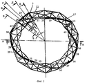
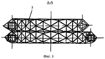
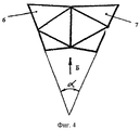
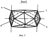
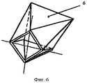
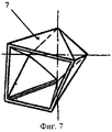
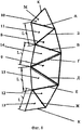
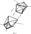
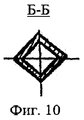
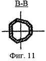
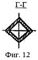
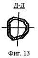
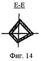
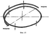
Сущность изобретения поясняется чертежами, где: на фиг.1 изображена малогабаритная установка для приготовления кормов, общий вид; на фиг.2 - рабочая камера, вид сверху; на фиг.3 - разрез А-А на фиг.2; на фиг.4 - одна из секций, из которых смонтирована рабочая камера, вид сверху; на фиг.5 - одна из секций, из которых смонтирована рабочая камера, вид по стрелке Б на фиг.4; на фиг.6 - одна из подсекций, секции рабочей камеры, аксонометрическая проекция; на фиг.7 - вторая подсекция, секции рабочей камеры, аксонометрическая проекция; на фиг.8 - полоса с размеченными прямыми линиями; на фиг.9 - схема сборки секции из подсекций; фиг.10 - сечение Б-Б на фиг.2; на фиг.11 - сечение В-В на фиг.2;, на фиг.12 - сечение Г-Г на фиг.2; на фиг 13 - сечение Д-Д на фиг.2; на фиг.14 - сечение Е-Е на фиг.2; фиг.15 - технологическая схема непрерывного приготовления кормов, наглядное изображение.The invention is illustrated by drawings, where: in Fig.1 shows a small-sized installation for the preparation of feed, General view; figure 2 - working chamber, top view; figure 3 is a section aa in figure 2; figure 4 is one of the sections from which the working chamber is mounted, top view; figure 5 is one of the sections from which the working chamber is mounted, view along arrow B in figure 4; figure 6 is one of the subsections, sections of the working chamber, axonometric projection; Fig.7 is a second subsection, sections of the working chamber, axonometric projection; on Fig - strip with marked straight lines; figure 9 - assembly diagram of the section from the subsections; figure 10 - section bB in figure 2; figure 11 is a section bb in figure 2;, figure 12 is a section gg in figure 2; in Fig.13 is a section DD in Fig.2; in Fig.14 is a cross-section EE in Fig.2; Fig - flow chart of the continuous preparation of feed, visual image.
Малогабаритная установка для приготовления кормов (фиг.1) состоит из станины 1, на которой с помощью пружин 2 упруго закреплена и снабжена вибратором 3 рабочая камера 4. Загрузочные и разгрузочные приспособления на фиг.1 не показаны.A small-sized feed preparation plant (Fig. 1) consists of a bed 1, on which a working chamber 4 is elastically fixed and equipped with a vibrator 3 using springs 2. Loading and unloading devices are not shown in Fig. 1.
Рабочая камера 4 (фиг.2, фиг.3) выполнена спиральной формы с многогранной винтовой поверхностью по ее внутреннему и наружному периметру и изготовлена из секций 5 (одна из секций на фиг.2 выделена сплошными утолщенными линиями), соединенным между собой известными методами, например сваркой, клейкой и т.п. Каждая из секций 5 изготовлена в виде кругового сектора (фиг.4, фиг.5, фиг.6, фиг.7) из подсекций 6 и 7. Подсекции 6 и подсекция 7 изготовлены из полос М (фиг.8), согнутых в одну сторону по прямым линиям А, Б, В, Г, Д, Е, Ж, размещенным под углом к боковым кромкам полосы М, с образованием разных по размерам равносторонних треугольников 8 и 9, при этом стороны треугольника 8 меньше стороны треугольника 9 на величину 2Δ, равнобедренных треугольников 10, 11, 12, 13 и двух одинаковых разносторонних треугольников 14 и 15. Все стороны этих треугольников отличаются друг от друга на одну и ту же линейную величину, кратную целому числу Δ. При этом с двух сторон самого большого равностороннего треугольника 9 своими самыми большими сторонами (стороной Г треугольника 14 и стороной Д треугольника 15) размещены два одинаковых разносторонних треугольника 14 и 15. Стороны, по которым присоединены треугольники 14 и 15 к треугольнику 9, показаны на фиг.8 двойными линиями. Средние по размерам стороны разносторонних треугольников 14 и 15 (сторона в треугольника 14 и сторона Е треугольника 15) меньше сторон большого равностороннего треугольника 9 на величину 2Δ. Самые маленькие стороны разносторонних треугольников 14 и 15 меньше средних их сторон В и Е на величину Δ и равны величине L. Эти стороны (L) показаны на фиг.8. К средней стороне В разностороннего треугольника 14 прикреплен равносторонний треугольник 8, все стороны которого равны средней стороне В треугольника 14. К стороне Б треугольника 8 прикреплен своим основанием равнобедренный треугольник 11, боковые стороны которого меньше его основания на величину Δ и соответственно меньше стороны самого большого треугольника 9 на величину 3Δ. К стороне треугольника 11 прикреплен своей боковой стороной А равнобедренный треугольник 10, основание которого меньше его боковой стороны на величину Δ и соответственно меньше сторон самого большого равностороннего треугольника 9 на величину 4Δ. С противоположной стороны полосы М к средней стороне Е треугольника 15 прикреплен своей боковой стороной равнобедренный треугольник 12, основание которого меньше его боковой стороны на величину Δ и соответственно меньше сторон треугольника 9 на величину 3Δ. К стороне Ж - основанию треугольника 12, прикреплен своей боковой стороной равнобедренный треугольник 13, основание которого меньше его боковой стороны на величину Δ и соответственно меньше сторон самого большого равностороннего треугольника 9 на величину 4Δ.The working chamber 4 (figure 2, figure 3) is made of a spiral shape with a polyhedral helical surface along its inner and outer perimeter and made of sections 5 (one of the sections in figure 2 is highlighted by solid thickened lines), interconnected by known methods, e.g. welding, sticky, etc. Each of the
После сгиба полосы М по линиям А, Б, В, Г, Д, Е, Ж в кольцо в одну сторону концы полосы М по линиям К (на фиг.6 и7 показаны тройной линией) соединяют, например сваркой, с образованием подсекций 6 и 7 (фиг.6 и фиг.7), у которых с одной стороны образовано отверстие в виде квадрата с стороной, равной L, длина которой меньше сторон самого большого равностороннего треугольника 9 полосы М на величину 3Δ, а с другой стороны образовано отверстие в виде равнобедренной трапеции, большое основание которой равно стороне самого большого равностороннего треугольника 9, малое основание меньше большого основания трапеции на величину 3Δ, а боковые стороны меньше большого основания на 2Δ.After bending the strip M along the lines A, B, C, D, D, E, Zh into a ring in one direction, the ends of the strip M along the lines K (shown in Figs. 6 and 7 by a triple line) are connected, for example, by welding, with the formation of
Подсекции 6 и 7 соединяют отверстиями в виде трапеций (фиг.9) с образованием секции 5, например сваркой. Таким образом секция 5 (фиг.4, фиг.5) снабжена входным квадратным отверстием Р и выходным квадратным отверстием С, причем стороны квадратных входных и выходных отверстий Р и С секции 5 равны друг другу. При этом квадратные отверстия Р и С секции 5 расположены друг к другу под углом α, величина которого обеспечивает спиральную форму корпуса 4.
При монтаже секций 5 в рабочую камеру 4 их соединяют квадратными отверстиями, при этом поочередно поворачивают их на 90° каждую последующую секцию относительно предыдущей по часовой стрелке, а затем следующую секцию присоединяют с поворотом в обратном направлении тоже на 90°.When the
На наружной и внутренней поверхности спиральной рабочей камеры 4 образованы взаимонаправленные ломаные винтовые линии, например, как показано на фиг.2 утолщенной линией одна из восьми ломанных винтовых линий: 16-17-18-19-20-21-22-23-24-25-26-27-28-29-30-31-32-33-34-35-36-37-38-39-40-41-42-43 и т.д. На фиг.2 невидимые участки ломаной винтовой линии показаны двойной штриховой линией, а вершины их взяты в круглые скобки.On the outer and inner surfaces of the spiral working chamber 4, mutually directed broken helical lines are formed, for example, as shown in FIG. 2 with a thickened line, one of eight broken helical lines: 16-17-18-19-20-21-22-23-23-24- 25-26-27-28-29-30-31-32-33-34-35-36-37-38-39-40-41-42-43, etc. In Fig.2, the invisible sections of the broken helix are shown by a double dashed line, and their vertices are taken in parentheses.
В результате по внутренней и наружной поверхностям спиральной формы рабочей камеры 4 образованы винтовые поверхности с различными по форме и площади сечениями, а сама рабочая камера 4 спиральной формы имеет проходное сечение, которое меняется по все длине рабочей камеры как по площади, так и по размерам и по форме (фиг.11, фиг.12, фиг.13, фиг.14, фиг.15).As a result, helical surfaces with different cross-sectional shapes and areas are formed on the inner and outer surfaces of the spiral shape of the working chamber 4, and the working chamber 4 of the spiral shape itself has a cross-section that varies along the entire length of the working chamber both in area and size and in shape (Fig. 11, Fig. 12, Fig. 13, Fig. 14, Fig. 15).
Таким образом, рабочая камера 4 (фиг.1, фиг.2, фиг.3) выполнена по периметру в виде многозаходной винтовой поверхности с винтовыми линиями по периметру рабочей камеры 4 и с переменным проходным сечением, обеспечивающим поджатие компонентов кормов.Thus, the working chamber 4 (Fig. 1, Fig. 2, Fig. 3) is made around the perimeter in the form of a multi-helical surface with helical lines around the perimeter of the working chamber 4 and with a variable bore, providing compression components of the feed.
Рабочая камера 4 (фиг.2, фиг.3) спиральной формы с многогранной винтовой поверхностью по его внутреннему и наружному периметру с образованием по его наружной и внутренней поверхностям многозаходных винтовых поверхностей и однонаправленных многозаходных винтовых линий может быть изготовлена и иным способом.The working chamber 4 (figure 2, figure 3) of a spiral shape with a polyhedral helical surface along its inner and outer perimeter with the formation of multi-helical surfaces and unidirectional multi-helical lines along its outer and inner surfaces can be made in another way.
Малогабаритная установка для приготовления кормов работает следующим образом.Small-sized installation for the preparation of feed works as follows.
Возмущающая сила вибратора 3 через стенки рабочей камеры 4 передается частицам компонентов кормов, находящимся внутри рабочей камеры 4. Частицы компонентов кормов совершают сложное движение, при котором и происходит процесс приготовления кормов. Частицы компонентов кормов интенсивно взаимодействуют друг с другом и под воздействием вибрации совершают вращательное движение в плоскостях, перпендикулярных проходному сечению рабочей камеры 4. Так как по длине рабочей камеры 4 размеры поперечного сечения, форма и расположение меняются, то усугубляется нарушаемость движения частиц компонентов кормов, т.е. имеет место повышение интенсивности их приготовления. Наличие винтовых поверхностей и винтовых линий по периметру рабочей камеры 4 способствует не только усложнению траекторий движения частиц компонентов кормов, но и их перемещению по проходному сечению рабочей камеры 4 от загрузки (фиг.15) к выгрузке. При движении по проходному сечению рабочей камеры 4 частиц кормов из-за изменения проходного сечения по форме и размерам образуются попеременно зоны сжатия и разряжения в каждом сечение рабочей камеры 4 по всему ее объему, что тоже интенсифицирует процесс приготовления кормов и расширяет технологические возможности.The perturbing force of the vibrator 3 through the walls of the working chamber 4 is transmitted to the particles of the feed components located inside the working chamber 4. The particles of the feed components make a complex movement, during which the process of preparing the feed occurs. Particles of feed components intensively interact with each other and under the influence of vibration rotate in planes perpendicular to the bore of the working chamber 4. Since the dimensions of the cross section along the length of the working chamber 4 change in shape and location, the disturbed movement of the particles of the feed components is aggravated, t .e. there is an increase in the intensity of their preparation. The presence of helical surfaces and helical lines around the perimeter of the working chamber 4 contributes not only to the complication of the trajectories of the particles of feed components, but also to their movement along the bore of the working chamber 4 from loading (Fig. 15) to unloading. When moving along the cross section of the working chamber 4 feed particles due to changes in the cross section in shape and size, compression and vacuum zones are alternately formed in each cross section of the working chamber 4 over its entire volume, which also intensifies the process of preparing the feed and expands technological capabilities.
Технико-экономические преимущества возникают за счет выполнения рабочей камеры спиральной формы с многократным изменением проходного сечения по форме и размерам по всей ее длине и с образованием по ее наружному и внутреннему периметру многозаходных винтовых поверхностей и однонаправленных многозаходных винтовых линий, которые и обеспечивают изменение направления движения потоков частиц компонентов кормов и расширение технологических возможностей.Technical and economic advantages arise due to the implementation of a spiral-shaped working chamber with multiple changes in the bore in shape and size along its entire length and with the formation of multi-helical surfaces and unidirectional multi-helical lines along its outer and inner perimeter, which provide a change in the direction of flow particle feed components and the expansion of technological capabilities.
Claims (1)
Priority Applications (1)
| Application Number | Priority Date | Filing Date | Title |
|---|---|---|---|
| RU2013147260/13A RU2541663C1 (en) | 2013-10-22 | 2013-10-22 | Small-size plant for preparing feed |
Applications Claiming Priority (1)
| Application Number | Priority Date | Filing Date | Title |
|---|---|---|---|
| RU2013147260/13A RU2541663C1 (en) | 2013-10-22 | 2013-10-22 | Small-size plant for preparing feed |
Publications (1)
| Publication Number | Publication Date |
|---|---|
| RU2541663C1 true RU2541663C1 (en) | 2015-02-20 |
Family
ID=53288735
Family Applications (1)
| Application Number | Title | Priority Date | Filing Date |
|---|---|---|---|
| RU2013147260/13A RU2541663C1 (en) | 2013-10-22 | 2013-10-22 | Small-size plant for preparing feed |
Country Status (1)
| Country | Link |
|---|---|
| RU (1) | RU2541663C1 (en) |
Cited By (3)
| Publication number | Priority date | Publication date | Assignee | Title |
|---|---|---|---|---|
| RU2594883C1 (en) * | 2015-06-02 | 2016-08-20 | Федеральное государственное бюджетное образовательное учреждение высшего профессионального образования "Кубанский государственный аграрный университет" | Installation for preparation of feedstuffs |
| RU2594994C1 (en) * | 2015-06-03 | 2016-08-20 | Федеральное государственное бюджетное образовательное учреждение высшего профессионального образования "Кубанский государственный аграрный университет" | Machine for preparation of feedstuffs |
| RU2594993C1 (en) * | 2015-06-02 | 2016-08-20 | Федеральное государственное бюджетное образовательное учреждение высшего профессионального образования "Кубанский государственный аграрный университет" | Machine for preparation of feedstuffs |
Citations (4)
| Publication number | Priority date | Publication date | Assignee | Title |
|---|---|---|---|---|
| SU1722298A1 (en) * | 1990-07-03 | 1992-03-30 | Всесоюзный научно-исследовательский институт кормов им.В.Р.Вильямса | Shredder |
| RU2028070C1 (en) * | 1991-04-04 | 1995-02-09 | Серга Георгий Васильевич | Device for forage preparation |
| RU2358620C1 (en) * | 2008-03-11 | 2009-06-20 | Федеральное государственное образовательное учреждение высшего профессионального образования Кубанский государственный аграрный университет | Installation for preparing forage |
| RU2372817C1 (en) * | 2008-06-23 | 2009-11-20 | Федеральное государственное образовательное учреждение высшего профессионального образования "Кубанский государственный аграрный университет" | Device to mix fodders |
-
2013
- 2013-10-22 RU RU2013147260/13A patent/RU2541663C1/en not_active IP Right Cessation
Patent Citations (4)
| Publication number | Priority date | Publication date | Assignee | Title |
|---|---|---|---|---|
| SU1722298A1 (en) * | 1990-07-03 | 1992-03-30 | Всесоюзный научно-исследовательский институт кормов им.В.Р.Вильямса | Shredder |
| RU2028070C1 (en) * | 1991-04-04 | 1995-02-09 | Серга Георгий Васильевич | Device for forage preparation |
| RU2358620C1 (en) * | 2008-03-11 | 2009-06-20 | Федеральное государственное образовательное учреждение высшего профессионального образования Кубанский государственный аграрный университет | Installation for preparing forage |
| RU2372817C1 (en) * | 2008-06-23 | 2009-11-20 | Федеральное государственное образовательное учреждение высшего профессионального образования "Кубанский государственный аграрный университет" | Device to mix fodders |
Cited By (3)
| Publication number | Priority date | Publication date | Assignee | Title |
|---|---|---|---|---|
| RU2594883C1 (en) * | 2015-06-02 | 2016-08-20 | Федеральное государственное бюджетное образовательное учреждение высшего профессионального образования "Кубанский государственный аграрный университет" | Installation for preparation of feedstuffs |
| RU2594993C1 (en) * | 2015-06-02 | 2016-08-20 | Федеральное государственное бюджетное образовательное учреждение высшего профессионального образования "Кубанский государственный аграрный университет" | Machine for preparation of feedstuffs |
| RU2594994C1 (en) * | 2015-06-03 | 2016-08-20 | Федеральное государственное бюджетное образовательное учреждение высшего профессионального образования "Кубанский государственный аграрный университет" | Machine for preparation of feedstuffs |
Similar Documents
| Publication | Publication Date | Title |
|---|---|---|
| RU2511208C1 (en) | Vibratory concrete mixer | |
| RU2541663C1 (en) | Small-size plant for preparing feed | |
| RU2473381C2 (en) | Device for producing paint-and-lacquer materials (versions) | |
| RU2548184C1 (en) | Vibratory unit for feed preparation | |
| RU2428306C2 (en) | Core concrete mixer (versions) | |
| RU2456096C2 (en) | Screen for sizing construction materials | |
| RU2467810C2 (en) | Toroidal device for cleaning seeds | |
| RU2506150C2 (en) | Vibratory device for finishing-and-skinning | |
| RU2572140C1 (en) | Low-size device for varnish-and-paint products manufacturing | |
| RU2347615C1 (en) | Toroidal device for separation of seeds | |
| RU2548187C1 (en) | Vibration unit for loose material mixing | |
| RU2548889C1 (en) | Vibration device for preparing feed | |
| RU2511135C2 (en) | Vibration screen | |
| RU2726053C1 (en) | Cement calcining furnace | |
| RU2465131C2 (en) | Mortar preparation vibrator | |
| RU2548890C1 (en) | Vibration device for preparing feed | |
| RU2564712C1 (en) | Concrete mixer | |
| RU2478474C2 (en) | Vibratory concrete mixer | |
| RU2467871C2 (en) | Unit with toroidal working chamber for making mortars | |
| RU2610486C1 (en) | Continuously working concrete mixer | |
| RU2545339C2 (en) | Device for producing paint-and-lacquer materials | |
| RU2537718C1 (en) | Concrete mixer of continuous action | |
| RU2690622C1 (en) | Cement kiln | |
| RU2594994C1 (en) | Machine for preparation of feedstuffs | |
| RU2684794C1 (en) | Continuous concrete mixer |
Legal Events
| Date | Code | Title | Description |
|---|---|---|---|
| QB4A | Licence on use of patent |
Free format text: LICENCE Effective date: 20150703 |
|
| MM4A | The patent is invalid due to non-payment of fees |
Effective date: 20161023 |