RU2536681C2 - Laundry treatment machine - Google Patents
Laundry treatment machine Download PDFInfo
- Publication number
- RU2536681C2 RU2536681C2 RU2011153799/12A RU2011153799A RU2536681C2 RU 2536681 C2 RU2536681 C2 RU 2536681C2 RU 2011153799/12 A RU2011153799/12 A RU 2011153799/12A RU 2011153799 A RU2011153799 A RU 2011153799A RU 2536681 C2 RU2536681 C2 RU 2536681C2
- Authority
- RU
- Russia
- Prior art keywords
- drum
- tank
- length
- casing
- bearings
- Prior art date
Links
Images


Classifications
-
- D—TEXTILES; PAPER
- D06—TREATMENT OF TEXTILES OR THE LIKE; LAUNDERING; FLEXIBLE MATERIALS NOT OTHERWISE PROVIDED FOR
- D06F—LAUNDERING, DRYING, IRONING, PRESSING OR FOLDING TEXTILE ARTICLES
- D06F37/00—Details specific to washing machines covered by groups D06F21/00 - D06F25/00
- D06F37/20—Mountings, e.g. resilient mountings, for the rotary receptacle, motor, tub or casing; Preventing or damping vibrations
- D06F37/22—Mountings, e.g. resilient mountings, for the rotary receptacle, motor, tub or casing; Preventing or damping vibrations in machines with a receptacle rotating or oscillating about a horizontal axis
-
- D—TEXTILES; PAPER
- D06—TREATMENT OF TEXTILES OR THE LIKE; LAUNDERING; FLEXIBLE MATERIALS NOT OTHERWISE PROVIDED FOR
- D06F—LAUNDERING, DRYING, IRONING, PRESSING OR FOLDING TEXTILE ARTICLES
- D06F37/00—Details specific to washing machines covered by groups D06F21/00 - D06F25/00
- D06F37/02—Rotary receptacles, e.g. drums
- D06F37/04—Rotary receptacles, e.g. drums adapted for rotation or oscillation about a horizontal or inclined axis
-
- D—TEXTILES; PAPER
- D06—TREATMENT OF TEXTILES OR THE LIKE; LAUNDERING; FLEXIBLE MATERIALS NOT OTHERWISE PROVIDED FOR
- D06F—LAUNDERING, DRYING, IRONING, PRESSING OR FOLDING TEXTILE ARTICLES
- D06F37/00—Details specific to washing machines covered by groups D06F21/00 - D06F25/00
- D06F37/26—Casings; Tubs
- D06F37/266—Gaskets mounted between tub and casing around the loading opening
-
- D—TEXTILES; PAPER
- D06—TREATMENT OF TEXTILES OR THE LIKE; LAUNDERING; FLEXIBLE MATERIALS NOT OTHERWISE PROVIDED FOR
- D06F—LAUNDERING, DRYING, IRONING, PRESSING OR FOLDING TEXTILE ARTICLES
- D06F37/00—Details specific to washing machines covered by groups D06F21/00 - D06F25/00
- D06F37/26—Casings; Tubs
- D06F37/267—Tubs specially adapted for mounting thereto components or devices not provided for in preceding subgroups
- D06F37/268—Tubs specially adapted for mounting thereto components or devices not provided for in preceding subgroups for suspension devices
-
- D—TEXTILES; PAPER
- D06—TREATMENT OF TEXTILES OR THE LIKE; LAUNDERING; FLEXIBLE MATERIALS NOT OTHERWISE PROVIDED FOR
- D06F—LAUNDERING, DRYING, IRONING, PRESSING OR FOLDING TEXTILE ARTICLES
- D06F37/00—Details specific to washing machines covered by groups D06F21/00 - D06F25/00
- D06F37/26—Casings; Tubs
- D06F37/267—Tubs specially adapted for mounting thereto components or devices not provided for in preceding subgroups
- D06F37/269—Tubs specially adapted for mounting thereto components or devices not provided for in preceding subgroups for the bearing of the rotary receptacle
-
- D—TEXTILES; PAPER
- D06—TREATMENT OF TEXTILES OR THE LIKE; LAUNDERING; FLEXIBLE MATERIALS NOT OTHERWISE PROVIDED FOR
- D06F—LAUNDERING, DRYING, IRONING, PRESSING OR FOLDING TEXTILE ARTICLES
- D06F39/00—Details of washing machines not specific to a single type of machines covered by groups D06F9/00 - D06F27/00
- D06F39/12—Casings; Tubs
- D06F39/125—Supporting arrangements for the casing, e.g. rollers or legs
-
- F—MECHANICAL ENGINEERING; LIGHTING; HEATING; WEAPONS; BLASTING
- F16—ENGINEERING ELEMENTS AND UNITS; GENERAL MEASURES FOR PRODUCING AND MAINTAINING EFFECTIVE FUNCTIONING OF MACHINES OR INSTALLATIONS; THERMAL INSULATION IN GENERAL
- F16F—SPRINGS; SHOCK-ABSORBERS; MEANS FOR DAMPING VIBRATION
- F16F15/00—Suppression of vibrations in systems; Means or arrangements for avoiding or reducing out-of-balance forces, e.g. due to motion
- F16F15/02—Suppression of vibrations of non-rotating, e.g. reciprocating systems; Suppression of vibrations of rotating systems by use of members not moving with the rotating systems
- F16F15/022—Suppression of vibrations of non-rotating, e.g. reciprocating systems; Suppression of vibrations of rotating systems by use of members not moving with the rotating systems using dampers and springs in combination
-
- D—TEXTILES; PAPER
- D06—TREATMENT OF TEXTILES OR THE LIKE; LAUNDERING; FLEXIBLE MATERIALS NOT OTHERWISE PROVIDED FOR
- D06F—LAUNDERING, DRYING, IRONING, PRESSING OR FOLDING TEXTILE ARTICLES
- D06F37/00—Details specific to washing machines covered by groups D06F21/00 - D06F25/00
- D06F37/30—Driving arrangements
-
- Y—GENERAL TAGGING OF NEW TECHNOLOGICAL DEVELOPMENTS; GENERAL TAGGING OF CROSS-SECTIONAL TECHNOLOGIES SPANNING OVER SEVERAL SECTIONS OF THE IPC; TECHNICAL SUBJECTS COVERED BY FORMER USPC CROSS-REFERENCE ART COLLECTIONS [XRACs] AND DIGESTS
- Y02—TECHNOLOGIES OR APPLICATIONS FOR MITIGATION OR ADAPTATION AGAINST CLIMATE CHANGE
- Y02B—CLIMATE CHANGE MITIGATION TECHNOLOGIES RELATED TO BUILDINGS, e.g. HOUSING, HOUSE APPLIANCES OR RELATED END-USER APPLICATIONS
- Y02B40/00—Technologies aiming at improving the efficiency of home appliances, e.g. induction cooking or efficient technologies for refrigerators, freezers or dish washers
Abstract
Description
Область техники, к которой относится изобретениеFIELD OF THE INVENTION
Настоящее изобретение относится к машине для обработки белья.The present invention relates to a machine for processing linen.
В основном машины для обработки белья подразделяются на стиральные машины и сушильные машины. Такие стиральные машины включают в себя стиральные машины пульсаторного типа и стиральные машины барабанного типа, а также стиральные машины, имеющие функции стирки и сушки. Обычно сушильными машинами являются устройства для сушки влажного белья с использованием горячего воздуха и ему подобного.Basically, laundry machines are divided into washing machines and tumble dryers. Such washing machines include pulsator-type washing machines and drum-type washing machines, as well as washing machines having washing and drying functions. Typically, tumble dryers are devices for drying wet laundry using hot air and the like.
Предпосылки изобретенияBACKGROUND OF THE INVENTION
Такая стиральная машина барабанного типа включает в себя бак, расположенный горизонтально в ней, и барабан, горизонтально расположенный в баке. Белье, такое как одежда, загружают в барабан, и оно переворачивается за счет вращения барабана.Such a drum type washing machine includes a tub horizontally located therein and a drum horizontally located in the tub. The laundry, such as clothing, is loaded into the drum, and it is turned over by rotation of the drum.
Барабан расположен с возможностью вращения в баке.The drum is rotatably located in the tank.
Вал соединен с барабаном, и электродвигатель соединен с валом непосредственно или косвенно при помощи ремня. В результате при вращении электродвигателя барабан вращается.The shaft is connected to the drum, and the electric motor is connected to the shaft directly or indirectly with a belt. As a result, when the motor rotates, the drum rotates.
Барабан вращается во время циклов полоскания и сушки при быстром вращении, а также цикла стирки. Барабан вибрирует при вращении.The drum rotates during rinsing and drying cycles with rapid rotation, as well as the washing cycle. The drum vibrates during rotation.
В известных стиральных машинах вал проходит через бак. Корпус подшипника установлен для поддержания с возможностью вращения вала. Корпус подшипника запрессован с баком или закреплен на его задней стенке.In known washing machines, the shaft passes through the tank. The bearing housing is mounted to support rotation of the shaft. The bearing housing is pressed into the tank or mounted on its rear wall.
Вышеупомянутый корпус подшипника поддерживает вал, и вибрация барабана передается баку и корпусу подшипника через вал.The aforementioned bearing housing supports the shaft, and vibration of the drum is transmitted to the tank and bearing housing through the shaft.
Из-за этого бак вибрирует вместе с барабаном, и демпфирующий опорный элемент соединен с баком для уменьшения вибрации.Because of this, the tank vibrates with the drum, and a damping support element is connected to the tank to reduce vibration.
То есть известная стиральная машина выполнена таким образом, что вибрация барабана непосредственно передается баку, и демпфирующий опорный элемент поддерживает при соединении с опорой вибрацию.That is, the known washing machine is designed such that the vibration of the drum is directly transmitted to the tank, and the damping support element supports vibration when connected to the support.
Раскрытие изобретенияDisclosure of invention
Техническая проблемаTechnical problem
Настоящее изобретение описывает машину для обработки белья, в которой задняя конструкция выполнена более узкой для увеличения предельной нагрузки для стирки. В частности, описана машина для обработки белья, в которой для изготовления узкой задней конструкции расстояния между подшипниками и длина в направлении вперед-назад вращающегося вала уменьшены для увеличения размера или объема барабана. The present invention describes a laundry machine in which the rear structure is made narrower to increase the ultimate load for washing. In particular, a laundry machine is described in which, for the manufacture of a narrow rear structure, the distances between the bearings and the length in the front-back direction of the rotating shaft are reduced to increase the size or volume of the drum.
Решение проблемыSolution
Машина для обработки белья настоящего изобретения может включать в себя узел подвески, соединенный с узлом привода, для демпфирования вибрации с возможностью поддержания барабана. Хотя в известном уровне техники узел подвески соединен с баком для демпфирования как бака, так и барабана, машина для обработки белья настоящего изобретения может иметь конструкцию, в которой вибрация барабана изолирована от вибрации бака. При этом бак поддерживается более жестко, чем барабан, поддерживаемый узлом подвески.The laundry treating machine of the present invention may include a suspension assembly coupled to the drive assembly for damping vibration to support the drum. Although in the prior art the suspension unit is connected to the tank for damping both the tank and the drum, the laundry machine of the present invention may have a structure in which the vibration of the drum is isolated from the vibration of the tank. In this case, the tank is supported more rigidly than the drum supported by the suspension unit.
Пример, в котором бак поддерживается более жестко, чем барабан, поддерживаемый узлом подвески, описан ниже.An example in which the tank is supported more rigidly than the drum supported by the suspension unit is described below.
Во-первых, по меньшей мере, участок бака может быть выполнен как одно целое с кожухом.Firstly, at least a portion of the tank can be made integrally with the casing.
Во-вторых, бак может быть соединен с возможностью поддержания с помощью винтов, заклепок, резиновых втулок или закреплен с возможностью поддержания посредством сварки, герметизации клеем. В этом случае такой соединительный элемент имеет большую жесткость, чем узел подвески относительно направления основной вибрации барабана.Secondly, the tank can be connected with the possibility of maintaining with screws, rivets, rubber bushings or fixed with the possibility of maintaining by welding, sealing with glue. In this case, such a connecting element has greater rigidity than the suspension unit relative to the direction of the main vibration of the drum.
Кроме того, гибкий элемент может быть включен для уменьшения передачи вибрации барабана баку. Гибкий элемент может быть сделан для обеспечения гибкого соединения бака с узлом привода для предотвращения утечки из узла привода и бака и обеспечения возможности перемещения узла привода относительно бака. Таким гибким элементом может быть задняя прокладка.In addition, a flexible member may be included to reduce transmission of drum vibration to the tank. A flexible member can be made to provide a flexible connection between the tank and the drive assembly to prevent leakage from the drive and tank assembly and to allow the drive assembly to move relative to the tank. Such a flexible element may be a rear gasket.
Машиной для обработки белья в соответствии с предпочтительным вариантом осуществления настоящего изобретения может быть машина для обработки белья, в которой отношения расстояния между передним и задним подшипниками, диаметра, длины или объема барабана больше отношения расстояния между передним и задним подшипниками, диаметра, длины или объема барабана машины для обработки белья известного уровня техники.A laundry machine in accordance with a preferred embodiment of the present invention may be a laundry machine in which the ratio of the distance between the front and rear bearings, the diameter, length or volume of the drum is greater than the ratio of the distance between the front and rear bearings, the diameter, length or volume of the drum machines for processing linen of the prior art.
Чтобы сделать размер или объем барабана большим, задняя боковая конструкция может быть сделана узкой. Такое увеличение размера или объема барабана может увеличить предельную нагрузку для стирки.To make the size or volume of the drum large, the rear side structure can be made narrow. Such an increase in the size or volume of the drum may increase the ultimate load for washing.
Вышеупомянутые варианты осуществления могут быть объединены в различные формы, поскольку варианты осуществления не противоречат друг другу, для создания другого варианта осуществления.The above embodiments may be combined in various forms since the embodiments are not inconsistent with each other to create another embodiment.
Полезные эффекты настоящего изобретенияBeneficial effects of the present invention
Настоящее изобретение имеет следующие полезные эффекты.The present invention has the following beneficial effects.
Может быть создана машина для обработки белья, в которой задняя конструкция выполнена узкой, и размер или объем барабана увеличен, позволяя увеличить предельную нагрузку для стирки, даже если ее внешний размер не изменен по сравнению с машиной для обработки белья известного уровня техники.A laundry treating machine can be created in which the rear structure is narrow and the drum size or volume is increased to increase the ultimate load for washing even if its outer size is not changed compared to the prior art laundry treating machine.
Краткое описание чертежейBrief Description of the Drawings
Сопроводительные чертежи, которые включены для обеспечения дальнейшего понимания настоящего раскрытия и составляют часть данной заявки, иллюстрируют варианты осуществления раскрытия и вместе с описанием служат для объяснения принципа раскрытия.The accompanying drawings, which are included to provide a further understanding of the present disclosure and form part of this application, illustrate embodiments of the disclosure and, together with the description, serve to explain the principle of disclosure.
На чертежахIn the drawings
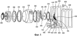
фиг.1 - перспективный вид с пространственным разделением элементов машины для обработки белья в соответствии с предпочтительным вариантом осуществления настоящего изобретения;figure 1 is a perspective view with a spatial separation of the elements of the machine for processing sheets in accordance with a preferred embodiment of the present invention;
фиг.2 - перспективный вид узла подвески, установленного на основании;figure 2 is a perspective view of the suspension unit mounted on the base;
фиг.3 и 4 - перспективные виды, каждый из которых показывает бак, задний элемент бака и заднюю прокладку, собранные вместе;3 and 4 are perspective views, each of which shows a tank, a rear tank element and a rear gasket assembled together;
фиг.5 иллюстрирует конструкцию для установки бака на плите основания;5 illustrates a structure for mounting a tank on a base plate;
фиг.6 иллюстрирует виды в продольном и поперечном сечениях, каждый из которых показывает зазоры между барабаном и баком.6 illustrates views in longitudinal and transverse sections, each of which shows the gaps between the drum and the tank.
фиг.7 показывает размер барабана и зазор между подшипниками.Fig.7 shows the size of the drum and the clearance between the bearings.
Лучший вариант осуществления изобретенияThe best embodiment of the invention
Ссылка будет сделана подробно на конкретные варианты осуществления настоящего изобретения, примеры которых проиллюстрированы на сопроводительных чертежах. Где возможно, подобные ссылочные позиции будут использоваться на чертежах для обозначения подобных элементов.Reference will be made in detail to specific embodiments of the present invention, examples of which are illustrated in the accompanying drawings. Where possible, similar reference numerals will be used throughout the drawings to refer to like elements.
Фиг.1 - перспективный вид с пространственным разделением элементов машины для обработки белья в соответствии с предпочтительным вариантом осуществления настоящего изобретения.Figure 1 is a perspective view with a spatial separation of the elements of the machine for processing sheets in accordance with a preferred embodiment of the present invention.
Машина для обработки белья содержит бак, неподвижно поддерживаемый на кожухе. Бак включает в себя переднюю часть 100 бака, которая является его переднем участком, и заднюю часть 120 бака, которая является его задним участком. Передняя часть 100 бака и задняя часть 120 бака соединяются с помощью винтов для образования пространства для вмещения барабана. Задняя часть 120 бака содержит отверстие на своей задней поверхности. Задняя часть 120 бака имеет внутреннюю окружность отверстия на задней поверхности, соединенную с наружной окружностью задней прокладки 250. Задняя прокладка 250 имеет внутреннюю окружность, соединенную с задним элементом 130 бака. Задний элемент 130 бака имеет сквозное отверстие в своем центре, через который проходит вращающийся вал. Задняя прокладка 250 выполнена из гибкого материала, так что вибрация не передается от заднего элемента 130 бака задней части 120 бака.The laundry treating machine comprises a tank fixedly supported on the casing. The tank includes a
Задняя прокладка 250 соединена с возможностью уплотнения с задним элементом 130 бака и задней частью 120 бака соответственно для предотвращения утечки воды из бака. Задний элемент 130 бака вибрирует вместе с барабаном при вращении барабана, когда задняя часть 120 бака расположена на соответствующем расстоянии от заднего элемента 130 бака, так что задний элемент 130 бака не создает помехи задней части 120 бака. Задняя прокладка 250 выполнена из гибкого материала, обеспечивая возможность осуществления относительного перемещения заднего элемента 130 бака без помехи задней части 120 бака. Задняя прокладка 250 содержит гофрированный участок, который может достаточно растягиваться для обеспечения такого относительного перемещения заднего элемента 130 бака.The
Элемент 200 для предотвращения проникновения постороннего вещества расположен на передней стороне передней части 100 бака для предотвращения проникновения посторонних веществ в зазор между баком и барабаном. Элемент 200 для предотвращения проникновения постороннего вещества выполнен из гибкого материала и закреплен на передней части 100 бака. Элемент 200 для предотвращения проникновения постороннего вещества может быть выполнен из того же материала, что и задняя прокладка 250.An
Барабан содержит переднюю часть 300 барабана, среднюю часть 320 барабана, заднюю часть 340 барабана и т.д. Шаровые противовесы могут быть установлены на передней части и задней части барабана, соответственно. Задняя часть 340 барабана соединяется с крестообразным элементом 350, и крестообразный элемент 350 соединяется с вращающимся валом 351. Барабан вращается внутри бака под действием вращающей силы, передаваемой ему через вращающийся вал 351.The drum comprises a
Вращающийся вал 351 проходит через задний элемент 130 бака и непосредственно соединяется с электродвигателем. Подробно, ротор электродвигателя (не показан) непосредственно соединяется с вращающимся валом. Корпус 400 подшипника соединяется с задней стороной заднего элемента 130 бака. Корпус 400 подшипника поддерживает с возможностью вращения вращающийся вал 351 между электродвигателем и задним элементом 130 бака.The
Статор 80 электродвигателя неподвижно установлен в корпусе 400 подшипника. Ротор расположен для окружения статора 80. Электродвигатель, являющийся электродвигателем с наружным ротором, непосредственно соединяется с вращающимся валом.The stator 80 of the electric motor is fixedly mounted in the bearing
Корпус 400 подшипника поддерживается на кожухе 600 при помощи узла подвески. Узел подвески включает в себя три вертикальные подвески и 2 наклонные подвески, установленные под наклоном в направлениях вперед-назад. Узел подвески соединяется с основанием 600 кожуха для обеспечения некоторой степени упругой деформации. То есть узел подвески упруго поддерживается относительно точек опоры, которые соединены с основанием, так что некоторая степень поворота узла подвески обеспечена в направлениях вперед-назад и направлениях влево-вправо относительно точки опоры. Чтобы сделать такое упругое поддержание доступным, вертикальные подвески могут быть установлены на основании 600 с помощью резиновых втулок, расположенных между ними. Подвески могут быть выполнены таким образом, что вертикальные подвески упруго демпфируют вибрацию барабана, а наклонные подвески уменьшают вибрацию. То есть в колебательной системе, которая включает в себя пружины и демпфирующие средства, вертикальные подвески используются в качестве пружин, а наклонные подвески используются в качестве демпфирующих средств. В этом случае тремя вертикальными поддерживающими подвесками являются пружины или пружинные демпферы (демпферы, которые используются в качестве демпферов, а также пружин), и двумя наклонными подвесками являются непружинные демпферы (демпферы, которые не используются в качестве пружин, а используются просто в качестве демпферов). Однако в другом варианте осуществления наклонные поддерживающие подвески могут также быть сделаны, чтобы использоваться в качестве пружинных демпферов.Bearing
Фиг.2 - перспективный вид узла подвески, установленного на основании 600 в состоянии, в котором узел подвески установлен на корпусе 400 подшипника. Узел подвески соединен с корпусом 400 подшипника для уменьшения вибрации барабана.FIG. 2 is a perspective view of a suspension assembly mounted on a base 600 in a state in which the suspension assembly is mounted on a bearing
Узел подвески может включать в себя кронштейны для соединения корпуса 400 подшипника с подвесками. Этими кронштейнами является радиальный кронштейн, который является радиальной выступающей частью, соединенной с корпусом 400 подшипника и проходящей в радиальном направлении, и осевой кронштейн, который является выступающей вперед частью, соединенной с радиальным кронштейном и проходящий вперед. Осевым кронштейном является выступающая часть в направлении оси вращения барабана.The suspension assembly may include brackets for connecting the bearing
Радиальный кронштейн включает в себя первый радиальный кронштейн 431 и второй радиальный кронштейн 430, которые расположены симметрично.The radial bracket includes a first
Первый радиальный кронштейн 431 и второй радиальный кронштейн 430 используются для соединения первого осевого кронштейна 450 и второго осевого кронштейна 440 с корпусом 400 подшипника соответственно.The first
Узел подвески может включать в себя подвески в направлениях вверх-вниз для уменьшения вибрации в направлениях вверх-вниз и подвески в направлениях вперед-назад для уменьшения вибрации в направлениях вперед-назад. Подвески в направлениях вверх-вниз могут быть расположены таким образом, что одна из подвесок в направлениях вверх-вниз расположена на задней стороне, а две на передней стороне относительно центра на левой и правой стороне, соответственно. Подвески в направлениях вперед-назад могут быть расположены на левой стороне и правой стороне в направлениях вперед-назад в наклонных положениях.The suspension assembly may include suspensions in the up and down directions to reduce vibration in the up and down directions and suspensions in the forward and back directions to reduce vibration in the forward and back directions. The pendants in the up and down directions can be arranged so that one of the pendants in the up and down directions is located on the rear side, and two on the front side relative to the center on the left and right side, respectively. The pendants in the front and back directions can be located on the left side and the right side in the front and back directions in inclined positions.
Подробно, как показано на фиг.2, в данном варианте осуществления узел подвески включает в себя первую пружину 520 цилиндра, вторую пружину 510 и третью пружину 500 цилиндра, и первый демпфер 540 цилиндра и второй демпфер 550 цилиндра.In detail, as shown in FIG. 2, in this embodiment, the suspension assembly includes a
Пружина цилиндра установлена между цилиндром и поршнем 624. Так как пружина цилиндра является комбинацией цилиндра и поршня, ее длина надежно изменяется во время демпфирования. Цилиндр соединен с осевым кронштейном, и поршень соединен с основанием.A cylinder spring is installed between the cylinder and piston 624. Since the cylinder spring is a combination of the cylinder and piston, its length reliably changes during damping. The cylinder is connected to the axial bracket, and the piston is connected to the base.
Демпфер цилиндра содержит поршень, перемещающийся в цилиндре для обеспечения демпфирующего эффекта за счет сопротивления трению. The cylinder damper comprises a piston moving in the cylinder to provide a damping effect due to friction resistance.
Первая пружина 520 цилиндра соединена между первым осевым кронштейном 450 и основанием 600. Вторая пружина 510 цилиндра соединена между вторым осевым кронштейном 440 и основанием 600. A
Третья пружина 500 цилиндра непосредственно соединена между корпусом 400 подшипника и основанием 600. A
Первый демпфер 540 цилиндра установлен под наклоном между первым осевым кронштейном 450 и задней стороной основания, и второй демпфер 530 цилиндра установлен под наклоном между вторым осевым кронштейном 440 и задней стороной основания.The
Третья пружина цилиндра расположена в центре задней стороны, а первая пружина цилиндра и вторая пружина цилиндра установлены на левой-правой сторонах передней стороны основания. Между задней стороной третьей пружины 500 цилиндра и передней стороной первого демпфера 540 цилиндра и второго демпфера 550 цилиндра расположены первый демпфер 540 цилиндра и второй демпфер 550 цилиндра. Они являются симметричными в направлениях влево-вправо.The third cylinder spring is located in the center of the rear side, and the first cylinder spring and the second cylinder spring are mounted on the left-right sides of the front side of the base. Between the rear side of the
Пружины цилиндра соединены с основанием 600 с помощью резиновых втулок, расположенных между ними.The cylinder springs are connected to the base 600 using rubber bushings located between them.
При этом пружина цилиндра может быть выполнена также для приложения демпфирующего усилия. В этом случае пружина цилиндра становится пружинным демпфером. Демпфер цилиндра может содержать пружину, установленную на нем. В этом случае демпфер цилиндра больше не является непружинным демпфером, а является пружинным демпфером.In this case, the cylinder spring can also be made for applying damping forces. In this case, the cylinder spring becomes a spring damper. The damper of the cylinder may contain a spring mounted on it. In this case, the cylinder damper is no longer a non-spring damper, but a spring damper.
В данном варианте осуществления бак неподвижно установлен на кожухе, так что вибрация барабана демпфируется с возможностью поддержания узлом подвески. Фактически, можно сказать, что это находится в режиме, в котором опорные конструкции для поддержания бака и барабана отделены друг от друга, и также можно сказать, что это находится в режиме, в котором барабан не вибрирует, даже если вибрирует бак. Подробно, бак может быть установлен, чтобы стоять самостоятельно на основании 600, причем его передняя сторона неподвижно соединена с передней частью кожуха (не показана), а его задняя сторона неподвижно соединена с задней частью 620 кожуха. In this embodiment, the tank is fixedly mounted on the casing, so that the vibration of the drum is damped so that it can be supported by the suspension unit. In fact, it can be said that it is in a mode in which the supporting structures for supporting the tank and the drum are separated from each other, and it can also be said that it is in a mode in which the drum does not vibrate, even if the tank vibrates. In detail, the tank can be installed to stand on its own on the
Фиг.3 и 4 - перспективные виды, каждый из которых показывает переднюю часть 100 бака, заднюю часть 120 бака, задний элемент 130 бака и заднюю прокладку 250, собранные вместе.Figures 3 and 4 are perspective views, each of which shows a
Как описано выше, передняя часть 100 бака неподвижно соединена с передней частью кожуха. Чтобы сделать такое неподвижное соединение доступным, четыре выступа образованы, по существу, вокруг отверстия для белья на его передней стороне. После расположения передней части кожуха в состоянии, в котором установлена передняя часть 100 бака, винты закручивают от передней стороны к задней стороне для закрепления передней части кожуха. As described above, the front of the
Под передней частью 100 бака расположен соединительный участок основания для установки передней части 100 бака на основании 600. Соединительный участок основания включает в себя цилиндрический первый полый соединительный участок 108a, цилиндрический второй полый соединительный участок 108b и первый участок 109 для крепления винтами для крепления винтами. После расположения передней части 100 бака на основании 600 первый участок 109 для крепления винтами закрепляется от передней стороны к задней стороне с помощью винтов для соединения передней части 100 бака.Under the
Задняя часть 120 бака является цилиндрической для окружения барабана с открытым передним отверстием, каким оно является, и задней стороной, имеющей кольцеобразную заднюю поверхность 128. Передняя сторона соединена с возможностью уплотнения с передней частью 100 бака. Задняя поверхность 128 задней части 120 бака имеет соответственно диаметр, больший наружного диаметра заднего элемента 130 бака. Имеется зазор, который не препятствует задней поверхности 128 задней части 120 бака, даже если задний элемент 130 бака вибрирует. В зазоре, т.е. между задней поверхностью 128 задней части 120 бака и задним элементом 130 бака, закреплена задняя прокладка 250. Задняя прокладка 250 уплотняет зазор между задней поверхностью 128 задней части 120 бака и задним элементом 130 бака. Задняя прокладка 250 может иметь соответствующий гибкий гофрированный участок, чтобы не передавать вибрацию заднего элемента 130 бака задней части 120 бака.The
Задняя часть 120 бака содержит соединительный участок 123 для соединения с задней частью 620 кожуха. The
Задняя часть 120 бака неподвижно закреплена на основании 600 кожуха, и чтобы сделать это, задняя часть 120 бака содержит третий полый соединительный участок 125a, причем третий полый соединительный участок 125a и второй участок 126 для крепления винтами образованы на нижней стороне задней части 120 бака. Участок для крепления винтами находится в режиме, в котором винты закрепляются в состоянии, в котором задняя часть 120 бака соединена с основанием.The
Второй участок 126 для крепления винтами не расположен на одной линии с первым участком 109 для крепления винтами, образованном на передней части 100 бака в направлениях вперед-назад, а вне линии. Если смотреть от передней стороны к задней стороне первый участок 109 для крепления винтами расположен на правой стороне, а второй участок 126 для крепления винтами расположен на левой стороне.The second
Соединительный участок основания образован для каждой из передней части 100 бака и задней части 120 бака для обеспечения взаимозаменяемости задней части 120 бака. В зависимости от предельных нагрузок машины для обработки белья, даже если используется передняя часть 100 бака одной конструкции, задняя часть бака может использоваться с возможностью взаимозаменяемости с другими задними частями бака, имеющими разные длины. В этом случае, так как может потребоваться изменение задней части 120 бака в состоянии, когда передняя часть 100 бака установлена на основании, может быть предпочтительным, чтобы соединительный участок основания был образован как для передней части 100 бака, так и задней части 120 бака.A connecting portion of the base is formed for each of the front of the
Установка бака на опорной передней части 50 для бака и задней опорной части 55 для бака будет описана со ссылкой на фиг.3 и 4. Сначала первую резиновую втулку 51 опорной передней части 50 для бака устанавливают в первом полом соединительном участке 108a передней части 108b бака, а вторую резиновую втулку 52 опорной передней части 50 для бака устанавливают во втором полом соединительном участке 108b. Относительно участков 53 и 58 для крепления винтами опорной передней части 50 для бака, участок 109 для крепления винтами передней части 100 бака устанавливают и закрепляют винтами с участком 53 для крепления винтами на его правой стороне. В этом случае винт закрепляют от передней стороны к задней стороне.The installation of the tank on the supporting
Третью резиновую втулку 56 опорной задней части 55 для бака устанавливают в третьем полом соединительном участке 125a задней части 120 бака, и четвертую резиновую втулку 57 опорной задней части 120 бака устанавливают в четвертом полом соединительном участке 125b. Относительно участков для крепления винтами опорной задней части 55 для бака участок 126 для крепления винтами задней части 120 бака устанавливают и закрепляют с помощью винтов с участком 58 для крепления винтами на его левой стороне. В этом случае винт закрепляют от задней стороны к передней стороне.A
Так как машина для обработки белья настоящего изобретения имеет вибрацию бака, значительно уменьшенную в отличие от известного уровня техники, зазор для вибрации не нужен, давая возможность максимально близко расположить наружную поверхность бака к кожуху. Даже если размер кожуха не увеличен, размер бака может быть увеличен, обеспечивая получения результата, в котором предельная нагрузка машины для обработки белья увеличена при том же самом внешнем размере. Фактически, зазор между правой частью 630 кожуха или левой частью 640 кожуха и баком может быть уменьшен до размера, меньшего 20 мм. В данном варианте осуществления зазор между наружной поверхностью бака и кожухом находится в диапазоне 5 мм. В этом случае, если принимаются во внимание ребра, образованные на наружной поверхности бака, зазор между наружной поверхностью бака и кожухом находится в диапазоне 3 мм. В машине для обработки белья известного уровня техники, в которой бак вибрирует вместе с барабаном, зазор находится в диапазоне 30 мм для предотвращения помех со стороны вибрации бака кожуху. Если рассматривается диаметр бака, машина для обработки белья настоящего изобретения может иметь бак с диаметром на 50 мм больше известного уровня техники. Так как размер бака, таким образом, увеличен, объем барабана, установленного в баке, может быть увеличен. Даже если машина для обработки белья настоящего изобретения имеет такой же внешний размер, что и машина для обработки белья известного уровня техники, машина для обработки белья, у которой предельная нагрузка при стирке увеличена за счет одного этапа, может быть получена. Since the laundry machine of the present invention has a vibration of the tank, significantly reduced in contrast to the prior art, a gap for vibration is not needed, making it possible to position the outer surface of the tank as close as possible to the casing. Even if the size of the casing is not increased, the size of the tank can be increased, providing a result in which the ultimate load of the laundry machine is increased at the same external size. In fact, the gap between the right side of the
При этом может быть благоприятным для сборки, чтобы бак не приводился в контакт с правой частью 630 кожуха или левой частью 640 кожуха, даже если размер бака не увеличен. Если определено, что размер бака соответствует правому-левому зазорам в кожухе (зазоры между правой частью кожуха и левой частью кожуха), сборка может быть нежелательной из-за помехи между кожухом и баком. Кроме того, если помеха между кронштейнами узла подвески и баком также принимается во внимание, может быть благоприятным, чтобы бак был увеличен до некоторой степени, при которой бак не входит в контакт с правой частью 630 кожуха или левой частью 640 кожуха. Следовательно, бак может быть выполнен при увеличении до некоторой степени, при которой бак имеет зазор в диапазоне 3~10 мм с правой частью 630 кожуха или левой частью 640 кожуха.It may be favorable for assembly, so that the tank is not brought into contact with the
В этом случае диаметр отверстия для белья в барабане фактически может быть таким же или больше диаметра отверстия для белья в баке. Барабан может иметь передний конец, проходящий вперед для образования отверстия для белья. В этом случае передний конец барабана расположен позади отверстия для белья в баке. Кроме того, передний конец барабана расположен позади передней внутренней стенки бака. В варианте осуществления барабан расположен в пространстве между передней стенкой и задней стенкой бака.In this case, the diameter of the hole for the laundry in the drum may actually be the same or larger than the diameter of the hole for the laundry in the tub. The drum may have a front end extending forward to form a hole for the laundry. In this case, the front end of the drum is located behind the laundry hole in the tub. In addition, the front end of the drum is located behind the front inner wall of the tank. In an embodiment, the drum is located in the space between the front wall and the rear wall of the tank.
Зазор между барабаном 300 и баком будет описан со ссылкой на фиг.6. Предпочтительно, чтобы зазоры были образованы таким образом, чтобы зазор между передней верхней стороной барабана и внутренней периферийной поверхностью верхней части бака был меньше зазора между передней нижней стороной барабана и внутренней периферийной поверхностью нижней части бака.The gap between the
То есть зазор G1 между наружной периферийной поверхностью верхней стороны барабана и внутренней периферийной поверхностью верхней стороны бака образован меньше зазора G3 между наружной периферийной поверхностью нижней части барабана и внутренней периферийной поверхностью нижней части бака. Причина состоит в том, что барабан может смещаться вниз при загрузке белья в барабан.That is, the gap G1 between the outer peripheral surface of the upper side of the drum and the inner peripheral surface of the upper side of the tank is formed less than the gap G3 between the outer peripheral surface of the lower part of the drum and the inner peripheral surface of the lower part of the tank. The reason is that the drum may shift downward when loading laundry into the drum.
При этом что касается зазоров между наружной периферийной поверхностью задней стороны барабана и внутренней периферийной поверхностью задней стороны бака, можно также сделать, чтобы зазор с верхней стороной был меньше зазора с нижней стороной по той же самой причине.Moreover, with regard to the gaps between the outer peripheral surface of the rear side of the drum and the inner peripheral surface of the rear side of the tank, it is also possible to make the gap with the upper side less than the gap with the lower side for the same reason.
Предпочтительно, чтобы зазор G2 между передней поверхностью барабана и внутренней передней поверхностью бака был установлен таким, чтобы не создавалась помеха во время вибрации барабана в направлениях вперед-назад. В частности, зазор G2 может учитывать зазор между передним концом наружной периферийной поверхности передней части бака и внутренней поверхностью бака спереди переднего конца наружной периферийной поверхности передней части бака. В этом случае зазором G2 между барабаном и баком может быть зазор с учетом шаровых противовесов, установленных на передней части барабана (зазоры, описанные в других частях описания подобны). Если установлен шаровой противовес, зазором может быть зазор между передней поверхностью шарового противовеса и внутренней поверхностью бака, которая расположена спереди шарового противовеса.Preferably, the gap G2 between the front surface of the drum and the inner front surface of the tank is set so that there is no interference during vibration of the drum in the forward and backward directions. In particular, the gap G2 may take into account the gap between the front end of the outer peripheral surface of the front of the tank and the inner surface of the tank in front of the front end of the outer peripheral surface of the front of the tank. In this case, the gap G2 between the drum and the tank may be a gap taking into account the ball balances mounted on the front of the drum (the gaps described in other parts of the description are similar). If a ball counterweight is installed, the gap may be a gap between the front surface of the ball counterweight and the inner surface of the tank, which is located in front of the ball counterweight.
Следовательно, необходимо, чтобы передняя часть 320 барабана и передняя внутренняя периферийная поверхность сохраняли зазор, достаточный для предотвращения помехи со стороны барабана для бака, даже если барабан вибрирует в направлениях вперед-назад.Therefore, it is necessary that the front of the
При этом необходимо, чтобы зазор G4 между задней частью 330 барабана и задней внутренней периферийной поверхностью бака был образован таким образом, чтобы задняя часть 330 барабана или крестообразный элемент 340 не создавали помеху задней стороне бака во время вращения барабана.It is necessary that the gap G4 between the rear of the
То есть необходимо, чтобы зазор G4 был рассчитан с учетом вибрации в направлениях вперед-назад, поскольку вибрация в направлениях вперед-назад может возникать при вращении барабана. That is, it is necessary that the clearance G4 is calculated taking into account vibration in the forward-backward directions, since vibration in the forward-backward directions can occur when the drum rotates.
Кроме того, зазоры в направлениях влево-вправо между наружной периферийной поверхностью барабана и внутренней периферийной поверхностью бака рассчитываются с учетом вибрации барабана в направлениях влево-вправо.In addition, the gaps in the left-right directions between the outer peripheral surface of the drum and the inner peripheral surface of the tank are calculated taking into account the vibration of the drum in the left-right directions.
В этом случае, если зазор в направлениях влево-вправо минимизирован за счет сведения к минимуму смещения барабана. Диаметр барабана определяет предельную нагрузку машины для обработки белья. Так как чем больше становится диаметр барабана, тем больше становится внутренний объем барабана, позволяя сделать больше предельную нагрузку машины для обработки белья. Что касается ширины в направлениях вперед-назад, ширины в направлениях влево-вправо, ширины в направлениях вверх-вниз машина для обработки белья, если ширина в направлениях влево-вправо является наименьшей, диаметр барабана не может определяться только с учетом ширины в направлениях влево-вправо. В этом случае, так как перемещение в направлениях влево-вправо барабана минимизировано, зазор в направлениях влево-вправо между барабаном и баком может быть минимизирован, диаметр барабана может быть максимизирован.In this case, if the clearance in the left-right directions is minimized by minimizing the displacement of the drum. The diameter of the drum determines the ultimate load of the laundry machine. Since the larger the diameter of the drum becomes, the larger the internal volume of the drum becomes, allowing the ultimate load of the laundry machine to be increased. As for the width in the forward-backward directions, the width in the left-right directions, the width in the up-down directions, the laundry machine, if the width in the left-right directions is the smallest, the diameter of the drum cannot be determined only by considering the width in the left-and-right directions to the right. In this case, since the movement in the left-right directions of the drum is minimized, the gap in the left-right directions between the drum and the tank can be minimized, the diameter of the drum can be maximized.
Что касается зазоров между барабаном и баком, диаметр барабана может быть максимизирован насколько возможно, делая сумму зазоров (G5+G6) в направлениях влево-вправо меньше суммы других зазоров (G1+G3 или G2+G4). В данном варианте осуществления барабан и бак имеют отношение, при котором сумма зазоров (G5+G6) в направлениях влево-вправо < суммы зазоров (G2+G4) в направлениях вперед-назад < суммы зазоров (G1+G3) в направлениях вверх-вниз. As for the gaps between the drum and the tank, the diameter of the drum can be maximized as much as possible by making the sum of the gaps (G5 + G6) in the left-right directions less than the sum of the other gaps (G1 + G3 or G2 + G4). In this embodiment, the drum and the tank have a relationship in which the sum of the gaps (G5 + G6) in the left-right directions <the sum of the gaps (G2 + G4) in the forward-backward directions <the sum of the gaps (G1 + G3) in the up-down directions .
Зазоры G1, G2, G3, G4, G5 и G6 могут быть образованы в качестве зазоров, которые учитывают помеху между барабаном и баком. Следовательно, если один элемент нужно установить в положении с зазором, необходимо определить зазор с учетом данного элемента. Случай шарового противовеса может быть одним примером. Ради удобства зазоры могут называться зазорами помехи. То есть можно определить, что G1 является зазором помехи в направлениях вверх-вниз бака до передней верхней стороны барабана, G2 является зазором помехи в направлениях вперед-назад бака до передней верхней стороны барабана, G3 является зазором помехи в направлениях вверх-вниз бака до передней нижней стороны барабана, G4 является зазором помехи в направлениях вперед-назад бака до передней нижней стороны барабана, G5 является зазором помехи в направлениях вверх-вниз бака до правой стороны барабана, и G6 является зазором помехи в направлениях влево-вправо до левой стороны барабана. В этом случае правая сторона или левая сторона обозначает левую сторону или правую сторону машины для обработки белья, если смотреть на машину для обработки белья позади белья по направлению к передней стороне машины для обработки белья.Gaps G1, G2, G3, G4, G5 and G6 can be formed as gaps that take into account the interference between the drum and the tank. Therefore, if one element needs to be installed in a position with a gap, it is necessary to determine the gap taking into account this element. The ball counterweight case may be one example. For the sake of convenience, clearances may be called interference clearances. That is, it can be determined that G1 is the interference gap in the up and down directions of the tank to the front upper side of the drum, G2 is the interference gap in the forward and back directions of the tank to the front upper side of the drum, G3 is the interference gap in the up and down directions of the tank to the front the lower side of the drum, G4 is the interference gap in the forward and backward directions of the tank to the front lower side of the drum, G5 is the interference gap in the up and down directions of the tank to the right side of the drum, and G6 is the interference gap in the directions on the right to the left-side of the drum. In this case, the right side or the left side denotes the left side or the right side of the laundry machine when looking at the laundry machine behind the laundry toward the front side of the laundry machine.
Для минимизации смещения в направлениях влево-вправо барабана во время вибрации барабана узел подвески может быть выполнен таким образом, что его жесткость относительно смещения в направлениях влево-вправо барабана больше его жесткости относительно смещения в направлениях вверх-вниз или направлениях вперед-назад барабана. По той же самой причине осевой кронштейн может быть выполнен таким образом, что момент инерции его сечения относительно оси в направлениях вверх-вниз больше момента инерции его сечения относительно оси в направлениях влево-вправо.To minimize displacement in the left-right directions of the drum during vibration of the drum, the suspension unit can be made in such a way that its stiffness with respect to the displacement in the left-right directions of the drum is greater than its stiffness with respect to displacement in the up-down or back-and-forth directions of the drum. For the same reason, the axial bracket can be made in such a way that the moment of inertia of its section relative to the axis in the up and down directions is greater than the moment of inertia of its section relative to the axis in the left-right directions.
При этом как описано выше, чтобы сделать объем барабана насколько можно больше, необходимо сделать объем бака также больше. В частности, чем больше ширина в направлениях влево-вправо внутренней периферийной поверхности бака, тем больше можно сделать диаметр барабана. Чтобы сделать это, желательно, чтобы левая сторона и правая сторона бака проходили, чтобы находиться в контакте с левой частью кожуха и правой частью кожуха, или чтобы, соответственно, находиться ближе к левой части кожуха и правой части кожуха насколько возможно. Предпочтительно со ссылкой на горизонтальную линию в направлениях влево-вправо, проходящую через центр барабана, делая разность между шириной в направлениях влево-вправо (расстояние между передней частью кожуха и правой частью кожуха) и наружным диаметром барабана меньше 100 мм, объем барабана можно сделать больше по сравнению с машиной для обработки белья известного уровня техники, имеющей такую же ширину в направлениях влево-вправо, таким образом, позволяя создать машину для обработки белья с увеличенной предельной нагрузкой. Так как чем меньше смещение в направлениях влево-вправо барабана, тем больше может быть сделан диаметр барабана, это желательно для увеличения предельной нагрузки. Однако обеспечение меньшего смещения барабана в направлениях влево-вправо означает, что опорная жесткость в направлениях влево-вправо узла подвески относительно барабана является большой. Если жесткость является чрезмерно большой, виброхарактеристика барабана может быть нежелательной. Например, если барабан вращается с высокой скоростью чрезмерная вибрация может возникать в области устойчивого состояния при скорости свыше приблизительно 400 об/мин. С такой точки зрения желательно, чтобы разность между шириной в направлениях влево-вправо (расстояние между наружными поверхностями передней части кожуха и правой части кожуха) и наружным диаметром барабана поддерживалась более 80 мм.Moreover, as described above, in order to make the drum volume as large as possible, it is necessary to make the tank volume also larger. In particular, the larger the width in the left-right directions of the inner peripheral surface of the tank, the larger the diameter of the drum can be made. To do this, it is desirable that the left side and the right side of the tank extend in order to be in contact with the left side of the casing and the right side of the casing, or so that it is as close to the left side of the casing and the right side of the casing as possible. Preferably, with reference to a horizontal line in the left-right directions passing through the center of the drum, making a difference between the width in the left-right directions (the distance between the front of the casing and the right part of the casing) and the outer diameter of the drum is less than 100 mm, the volume of the drum can be made larger compared with the prior art laundry machine having the same width in the left-right directions, thereby allowing the creation of a laundry machine with an increased ultimate load. Since the smaller the displacement in the left-right directions of the drum, the larger the diameter of the drum can be made, this is desirable to increase the ultimate load. However, providing less displacement of the drum in the left-right directions means that the stiffness in the left-right directions of the suspension unit relative to the drum is large. If the stiffness is excessively large, the vibration characteristic of the drum may be undesirable. For example, if the drum rotates at a high speed, excessive vibration may occur in the steady state region at speeds above about 400 rpm. From this point of view, it is desirable that the difference between the width in the left-right directions (the distance between the outer surfaces of the front part of the casing and the right part of the casing) and the outer diameter of the drum is supported more than 80 mm
При быстром вращении может возникать переходная область вибрации, в которой амплитуда вибрации становится больше вследствие резонанса, так как скорость вращения барабана увеличивается, и если скорость вращения дополнительно увеличивается и проходит через переходную область вибрации, вибрация достигает устойчивого состояния, в котором амплитуда вибрации падает до сравнительно низкого постоянного уровня. Чрезмерной вибрацией может быть явление вибрации, при котором увеличение и уменьшение амплитуды барабана повторяется, или амплитуда вибрации ставится чрезмерно большой.During fast rotation, a transitional vibration region can occur in which the vibration amplitude becomes larger due to resonance, since the rotation speed of the drum increases, and if the rotation speed further increases and passes through the transitional vibration region, the vibration reaches a stable state in which the vibration amplitude drops to a comparatively low constant level. Excessive vibration may be a vibration phenomenon in which the increase and decrease in the amplitude of the drum is repeated, or the amplitude of the vibration is set too large.
Что касается горизонтальной линии в направлениях влево-вправо, проходящей через центр барабана, зазор между левой стороной или правой стороной барабана и баком может быть сделан в 1,5 раза больше зазора между левой стороной или правой стороной бака и левой частью кожуха или правой частью кожуха. То есть за счет уменьшения зазора между левой стороной или правой стороной бака и левой частью кожуха или правой частью кожуха, диаметр барабана может быть сделан больше насколько возможно. За счет увеличения бака путем максимального приближения к кожуху для обеспечения его внутреннего пространства, позволяя увеличить диаметр барабана, машина для обработки белья, предельная нагрузка которой значительно увеличена, может быть создана, даже если ее внешние размеры остаются такими же. Однако, если бак находится очень близко к правой части кожуха или левой части кожуха, может возникнуть неудобство при сборке, и так как существуют случаи, когда элементы, которые не должны создавать помеху баку (например, осевой кронштейн), также не должны создавать помеху правой части кожуха или левой части кожуха, расчет может быть сделан таким, чтобы отношение не превышало 8 с учетом вышеизложенного.As for the horizontal line in the left-right directions passing through the center of the drum, the gap between the left side or the right side of the drum and the tank can be made 1.5 times the gap between the left side or the right side of the tank and the left side of the casing or the right side of the casing . That is, by reducing the gap between the left side or the right side of the tank and the left side of the casing or the right side of the casing, the diameter of the drum can be made as large as possible. By increasing the tank by maximally approaching the casing to ensure its internal space, allowing to increase the diameter of the drum, a machine for processing laundry, the maximum load of which is significantly increased, can be created even if its external dimensions remain the same. However, if the tank is very close to the right side of the casing or the left side of the casing, there may be inconvenience during assembly, and since there are cases where elements that should not interfere with the tank (for example, an axial bracket) should also not interfere with the right part of the casing or the left part of the casing, the calculation can be made so that the ratio does not exceed 8, taking into account the foregoing.
Чем меньше становится разность между размером кожуха и диаметром барабана, который вращается и вибрирует в кожухе, тем больше предельная нагрузка барабана приближается к максимуму при ограничении внешнего размера машины для обработки белья. Разность позволяет больше увеличить предельную нагрузку машины для обработки белья по сравнению с внешним размером машины для обработки белья. Предельная нагрузка машины для обработки белья может определяться максимальным количеством белья, т.е. количеством белья, которое машина для обработки белья может стирать. Например, стиральная машина класса 9 кг или 11 кг вмещает максимальное количество белья 9 кг или 11 кг соответственно. Обычно так как объемы барабана и бака необходимо увеличить, так как предельная нагрузка машины для обработки белья увеличивается, внешний размер машины для обработки белья не может только увеличиваться.The smaller the difference between the size of the casing and the diameter of the drum that rotates and vibrates in the casing, the greater the ultimate load of the drum approaches maximum when limiting the external size of the laundry machine. The difference makes it possible to increase the ultimate load of the laundry machine more than the external size of the laundry machine. The maximum load of the laundry machine can be determined by the maximum amount of laundry, i.e. the amount of laundry that the laundry machine can wash. For example, a washing machine of class 9 kg or 11 kg holds a maximum amount of linen of 9 kg or 11 kg, respectively. Usually, since the volumes of the drum and the tank need to be increased, since the ultimate load of the laundry machine increases, the external size of the laundry machine cannot only increase.
Вариант осуществления позволяет создать машину для обработки белья, имеющую предельную нагрузку, увеличенную больше по сравнению с машиной для обработки белья известного уровня техники относительно внешнего размера, в частности ширины в направлениях влево-вправо, машины для обработки белья. Хотя 24-х дюймовая машина для обработки белья известного уровня техники может обеспечивать предельную нагрузку класса 9 кг, машина для обработки белья данного варианта осуществления может обеспечивать предельную нагрузку класса 11 кг. Другими словами, что касается 24-х дюймового размера, машина для обработки белья сделана доступной, которая превышает предельную нагрузку, доступную в известном уровне техники (например, больше 9,5 кг), но предельная нагрузка которой меньше 11 кг. С другой стороны, объем барабана может быть увеличен приблизительно до 78 литров. Что касается 24-х дюймового размера, объем барабана может находиться в диапазоне 65-78 литров.An implementation option allows you to create a machine for processing sheets having a maximum load increased more compared to a machine for processing sheets of the prior art with respect to the external size, in particular the width in the left-right directions, of a machine for processing sheets. Although a 24-inch prior art laundry machine can provide a maximum load of class 9 kg, a laundry machine of this embodiment can provide an ultimate load of
В случае 27-ми дюймового размера машина для обработки белья, имеющая предельную нагрузку ниже 13 кг, которая превышает предельную нагрузку в известном уровне техники, может быть создана.In the case of a 27-inch size laundry machine having an ultimate load below 13 kg, which exceeds the ultimate load in the prior art, can be created.
Отношение между расстоянием между передним и задним подшипниками и диаметром, длиной или объемом барабана будут описаны со ссылкой на фиг.7. Корпус 400 подшипника содержит подшипники 491 и 492, установленные в нем на его передней стороне и задней стороне соответственно. Расстояние ℓ2 между центрами переднего подшипника 491 и заднего подшипника 492 влияет на толщину участка для поддержания подшипников, на котором подшипники 491 и 492 установлены в корпусе 400 подшипника. Расстояние ℓ2 также влияет на длину вала 351, который передает вращающую силу электродвигателя барабану. Так как ширина в направлениях вперед-назад приводного участка становится тем меньше, чем меньше становится расстояние ℓ2, узкая машина для обработки белья может быть создана. Расстояние ℓ2 может быть определено с учетом прочности вала 351 и подшипников, и образование расстояния ℓ2 меньше насколько возможно является благоприятным для создания узкой машины для обработки белья.The relationship between the distance between the front and rear bearings and the diameter, length or volume of the drum will be described with reference to Fig.7. The bearing
В отличие от машины для обработки белья известного уровня техники, так как машина для обработки белья настоящего изобретения имеет конструкцию, в которой корпус 400 подшипника не установлен на задней стенке бака, динамическая нагрузка на барабан не вызывает большую концентрацию напряжений на участке для поддержания подшипника корпуса 400 подшипника и участке для крепления статора (участок, на котором закреплен статор электродвигателя). Следовательно, ширины в направлениях вперед-назад, по меньшей мере, участка для поддержания подшипника и участка для крепления статора могут быть сделаны, по существу, меньше, чем ширины в направлениях вперед-назад, по меньшей мере, участка для поддержания подшипника и участка для крепления статора в известном уровне техники, соответственно. В противоположность этому, как описано выше, так как вибрация бака не является большой, бак может быть увеличен таким образом, что бак находится рядом с кожухом насколько возможно для увеличения объема барабана.In contrast to the prior art laundry treating machine, since the laundry treating machine of the present invention has a structure in which the bearing
Если расстояние ℓ2 между подшипниками уменьшено, и размер в направлениях вперед-назад, при котором расположен корпус 400 подшипника, уменьшен, длина в направлениях вперед-вправо барабана может быть увеличена для большего увеличения объема барабана.If the distance ℓ2 between the bearings is reduced and the size in the front-back directions at which the bearing
В этом случае за счет учета взаимосвязей между расстоянием (в дальнейшем, расстояние между подшипниками) между передним/задним подшипниками 491 и 492 и параметрами, которые определяют размер барабана, предельная нагрузка может быть увеличена, и узкая конструкция может быть создана. Расстояние между подшипниками может быть определено как расстояние между центрами подшипников, как показано на фиг.7.In this case, by taking into account the relationship between the distance (hereinafter, the distance between the bearings) between the front /
С этой точки зрения сначала будет рассмотрена взаимосвязь между расстоянием между подшипниками и диаметром барабана (центром 320 барабана). Отношение расстояния ℓ2 между подшипниками к диаметру D барабана может быть больше 9. В известном уровне техники отношение ниже 8,3, и отношение не может быть сделано больше отношения с конструктивной точки зрения. Однако, так как машина для обработки белья настоящего изобретения имеет совершенно новую конструкцию, отношение расстояния ℓ2 между подшипниками к диаметру D барабана может быть увеличено для создания узкой конструкции машины для обработки белья, имеющей увеличенную предельную нагрузку. Отношение расстояния ℓ2 между подшипниками к диаметру D барабана может быть ограничено, чтобы быть меньше 11,5. Причина состоит в том, что если отношение больше, может быть необходимым увеличение размера подшипника ввиду прочности, но не ограничиваясь этим. From this point of view, the relationship between the distance between the bearings and the diameter of the drum (
Вместе с тем, отношение расстояния ℓ2 между подшипниками к длине ℓ1 барабана может быть установлено больше 6,5. Также в известном уровне техники отношение ниже 6,2 вследствие конструктивных проблем, и отношение не может быть больше этого отношения. Хотя отношение расстояния ℓ2 между подшипниками к длине ℓ1 барабана также не ограничено, отношение может быть ограничено, чтобы быть меньше 8,6. В этом случае длина ℓ1 барабана может быть определена как длина между передней стенкой барабана и задней стенкой барабана, или длина ℓ2 в направлениях вперед-назад средней части барабана.At the same time, the ratio of the distance никами2 between the bearings to the length ℓ1 of the drum can be set to more than 6.5. Also in the prior art, the ratio is below 6.2 due to structural problems, and the ratio cannot be greater than this ratio. Although the ratio of the distance ℓ2 between the bearings to the length ℓ1 of the drum is also not limited, the ratio may be limited to be less than 8.6. In this case, the length ℓ1 of the drum can be defined as the length between the front wall of the drum and the rear wall of the drum, or the length ℓ2 in the front-back directions of the middle part of the drum.
Будет рассмотрена взаимосвязь между расстоянием ℓ2 между подшипниками и объемом барабана. Отношение расстояния ℓ2 между подшипниками к объему барабана может быть больше 1,3. В известном уровне техники отношение равно около 1,1 и не может быть больше этого отношения. Хотя отношение также не ограничено, отношение может быть ограничено, чтобы быть меньше 1,7. В этом случае расстояние между подшипниками измеряется в мм, и объем барабана измеряется в литрах.The relationship between the distance ℓ2 between the bearings and the drum volume will be considered. The ratio of the distance ℓ2 between the bearings to the drum volume can be more than 1.3. In the prior art, the ratio is about 1.1 and cannot be greater than this ratio. Although the ratio is also not limited, the ratio may be limited to be less than 1.7. In this case, the distance between the bearings is measured in mm, and the volume of the drum is measured in liters.
Хотя описано со ссылкой на расстояние ℓ2 между подшипниками, также может учитываться взаимосвязь между длиной вращающегося вала и размером или объемом барабана. В этом случае длиной вращающегося вала может быть длина вращающегося вала, установленного в корпусе подшипника. Такое отношение между длиной вращающегося вала и размером или объемом барабана может быть рассчитано за счет использования отношения между расстоянием между подшипниками и размером или объемом барабана, как оно есть. То есть что касается общей длины вращающегося вала, длина участка, расположенного в корпусе подшипника может использоваться вместо расстояния между подшипниками.Although described with reference to the distance ℓ2 between the bearings, the relationship between the length of the rotating shaft and the size or volume of the drum can also be taken into account. In this case, the length of the rotating shaft may be the length of the rotating shaft mounted in the bearing housing. This relationship between the length of the rotating shaft and the size or volume of the drum can be calculated by using the relationship between the distance between the bearings and the size or volume of the drum, as it is. That is, with regard to the total length of the rotating shaft, the length of the portion located in the bearing housing can be used instead of the distance between the bearings.
При этом несмотря на название задней прокладки, задняя прокладка может быть выполнена из различных материалов. Обычно кроме материалов, которые используются для образования прокладки, если прокладка может быть выполнена из материала, который может уменьшить скорость передачи вибрации от барабана баку, материал также может быть использован. Вместе с тем, если форма задней прокладки может относительно уменьшить передачу вибрации от барабана баку, конструкция задней прокладки может быть изменена, чтобы иметь такую форму.In this case, despite the name of the rear gasket, the rear gasket can be made of various materials. Usually, in addition to the materials that are used to form the gasket, if the gasket can be made of a material that can reduce the transmission speed of vibration from the drum to the tank, the material can also be used. However, if the shape of the rear gasket can relatively reduce the transmission of vibration from the drum to the tank, the design of the rear gasket can be changed to have such a shape.
Необходимо понимать, что названия, используемые для элементов настоящего изобретения, не истолковываются ограниченными значением в словаре или техническим значением. По меньшей мере, некоторые из названий элементов могут включать в себя названия, данные для удобства, и не ограничивают материал, функцию или форму элемента. Необходимо, чтобы элементы настоящего изобретения определялись и истолковывались за счет функций и назначений элементов.It should be understood that the names used for the elements of the present invention are not construed as having a limited meaning in a dictionary or technical meaning. At least some of the names of the elements may include names given for convenience, and do not limit the material, function, or shape of the element. It is necessary that the elements of the present invention are defined and interpreted due to the functions and purposes of the elements.
Специалистам в данной области техники следует понимать, что возможны различные модификации и изменения в настоящем изобретении без отхода от сущности и объема настоящего изобретения. Таким образом, подразумевается, что настоящее изобретение включает в себя модификации и изменения настоящего изобретения при условии, что они входят в объем прилагаемой формулы изобретения и ее эквивалентов.Specialists in the art should understand that various modifications and changes to the present invention are possible without departing from the essence and scope of the present invention. Thus, it is understood that the present invention includes modifications and variations of the present invention, provided that they are included in the scope of the attached claims and their equivalents.
Промышленная применимостьIndustrial applicability
Настоящее изобретение относится к машине для обработки белья. Машиной для обработки белья в соответствии с предпочтительным вариантом осуществления настоящего изобретения может быть машина для обработки белья, в которой отношения расстояния между передним и задним подшипниками, диаметра, длины или объема барабана больше отношений расстояния между передним и задним подшипниками, диаметра, длины или объема барабана машины для обработки белья известного уровня техники.The present invention relates to a machine for processing linen. A laundry machine in accordance with a preferred embodiment of the present invention may be a laundry machine in which the ratios of the distance between the front and rear bearings, the diameter, length or volume of the drum are greater than the ratios of the distance between the front and rear bearings, the diameter, length or volume of the drum machines for processing linen of the prior art.
Claims (5)
бак для содержания воды;
барабан, установленный с возможностью вращения в баке;
узел привода, включающий в себя вал, соединенный с барабаном, корпус подшипника для поддержания с возможностью вращения вала и электродвигатель для вращения вала;
узел подвески, закрепленный на корпусе подшипника, для уменьшения вибрации барабана, и
гибкий элемент для предотвращения утечки воды из бака к узлу привода и обеспечения перемещения узла привода относительно бака,
при этом диаметр барабана составляет от 9 до 11,5 длины участка вала, вставленного в корпус подшипника.1. Machine for processing linen containing
water tank;
a drum mounted rotatably in the tank;
a drive unit including a shaft connected to the drum, a bearing housing for supporting rotation of the shaft, and an electric motor for rotating the shaft;
a suspension assembly mounted on a bearing housing to reduce drum vibration, and
a flexible element to prevent leakage of water from the tank to the drive unit and to ensure movement of the drive unit relative to the tank,
the diameter of the drum is from 9 to 11.5 lengths of the shaft section inserted into the bearing housing.
Applications Claiming Priority (7)
| Application Number | Priority Date | Filing Date | Title |
|---|---|---|---|
| KR20090047192 | 2009-05-28 | ||
| KR10-2009-0047192 | 2009-05-28 | ||
| KR20090079829 | 2009-08-27 | ||
| KR10-2009-0079829 | 2009-08-27 | ||
| KR1020100047876A KR20100129175A (en) | 2009-05-28 | 2010-05-24 | Laundry machine |
| KR10-2010-0047876 | 2010-05-24 | ||
| PCT/KR2010/003402 WO2010137907A1 (en) | 2009-05-28 | 2010-05-28 | Laundry machine |
Publications (2)
| Publication Number | Publication Date |
|---|---|
| RU2011153799A RU2011153799A (en) | 2013-07-10 |
| RU2536681C2 true RU2536681C2 (en) | 2014-12-27 |
Family
ID=43505914
Family Applications (1)
| Application Number | Title | Priority Date | Filing Date |
|---|---|---|---|
| RU2011153799/12A RU2536681C2 (en) | 2009-05-28 | 2010-05-28 | Laundry treatment machine |
Country Status (9)
| Country | Link |
|---|---|
| US (1) | US20120017652A1 (en) |
| EP (1) | EP2435616A4 (en) |
| KR (1) | KR20100129175A (en) |
| CN (1) | CN102414359B (en) |
| AU (1) | AU2010253597B2 (en) |
| BR (1) | BRPI1012169A2 (en) |
| CA (1) | CA2760270A1 (en) |
| RU (1) | RU2536681C2 (en) |
| WO (1) | WO2010137907A1 (en) |
Families Citing this family (3)
| Publication number | Priority date | Publication date | Assignee | Title |
|---|---|---|---|---|
| EP2317001B1 (en) * | 2009-10-29 | 2016-05-25 | Electrolux Home Products Corporation N.V. | Household appliance for wall mounting |
| KR101373617B1 (en) | 2012-08-06 | 2014-03-12 | 동부대우전자 주식회사 | Wall mounted drum type washing machine |
| WO2017143552A1 (en) * | 2016-02-25 | 2017-08-31 | Tcl家用电器(合肥)有限公司 | Washing machine inner cylinder assembly and drum-type washing machine |
Citations (3)
| Publication number | Priority date | Publication date | Assignee | Title |
|---|---|---|---|---|
| SU986991A1 (en) * | 1981-07-09 | 1983-01-07 | Московский Технологический Институт Министерства Бытового Обслуживания Населения Рсфср | Machine for washing and wringing linen |
| EP1079014A1 (en) * | 1999-03-15 | 2001-02-28 | Kabushiki Kaisha Toshiba | Drum type washing machine |
| EP1746192A2 (en) * | 2004-07-20 | 2007-01-24 | Lg Electronics Inc. | Drum type washing machine and bearing housing structure thereof |
Family Cites Families (9)
| Publication number | Priority date | Publication date | Assignee | Title |
|---|---|---|---|---|
| KR100484839B1 (en) * | 2002-11-29 | 2005-04-22 | 엘지전자 주식회사 | tilted drum washer |
| EP2298979B1 (en) * | 2002-12-27 | 2014-04-09 | LG Electronics Inc. | Drum type washing machine |
| KR100464054B1 (en) * | 2002-12-27 | 2005-01-03 | 엘지전자 주식회사 | Drum type washing machine with united cabinet/tub |
| KR100587307B1 (en) * | 2004-06-09 | 2006-06-08 | 엘지전자 주식회사 | Drum type washing machine and drum of drum type washing machine |
| KR100743707B1 (en) * | 2005-02-03 | 2007-07-30 | 엘지전자 주식회사 | Drum washer having a tub coupled to cabinet and a drying device |
| JP3949145B2 (en) * | 2005-05-13 | 2007-07-25 | シャープ株式会社 | Drum washing machine |
| KR100786083B1 (en) * | 2006-03-29 | 2007-12-17 | 엘지전자 주식회사 | Top loading type drum washing machine |
| US7536882B2 (en) * | 2006-03-29 | 2009-05-26 | Lg Electronics Inc. | Drum type washing machine |
| KR101414599B1 (en) * | 2007-02-23 | 2014-07-03 | 엘지전자 주식회사 | Drum type washer |
-
2010
- 2010-05-24 KR KR1020100047876A patent/KR20100129175A/en not_active Application Discontinuation
- 2010-05-28 CN CN201080020149.6A patent/CN102414359B/en active Active
- 2010-05-28 AU AU2010253597A patent/AU2010253597B2/en active Active
- 2010-05-28 EP EP10780818.0A patent/EP2435616A4/en not_active Withdrawn
- 2010-05-28 RU RU2011153799/12A patent/RU2536681C2/en active
- 2010-05-28 CA CA2760270A patent/CA2760270A1/en not_active Abandoned
- 2010-05-28 WO PCT/KR2010/003402 patent/WO2010137907A1/en active Application Filing
- 2010-05-28 BR BRPI1012169A patent/BRPI1012169A2/en not_active Application Discontinuation
- 2010-05-28 US US13/259,626 patent/US20120017652A1/en not_active Abandoned
Patent Citations (3)
| Publication number | Priority date | Publication date | Assignee | Title |
|---|---|---|---|---|
| SU986991A1 (en) * | 1981-07-09 | 1983-01-07 | Московский Технологический Институт Министерства Бытового Обслуживания Населения Рсфср | Machine for washing and wringing linen |
| EP1079014A1 (en) * | 1999-03-15 | 2001-02-28 | Kabushiki Kaisha Toshiba | Drum type washing machine |
| EP1746192A2 (en) * | 2004-07-20 | 2007-01-24 | Lg Electronics Inc. | Drum type washing machine and bearing housing structure thereof |
Also Published As
| Publication number | Publication date |
|---|---|
| CN102414359A (en) | 2012-04-11 |
| BRPI1012169A2 (en) | 2016-03-29 |
| EP2435616A4 (en) | 2014-03-19 |
| WO2010137907A1 (en) | 2010-12-02 |
| AU2010253597B2 (en) | 2015-10-01 |
| KR20100129175A (en) | 2010-12-08 |
| CA2760270A1 (en) | 2010-12-02 |
| CN102414359B (en) | 2015-01-28 |
| RU2011153799A (en) | 2013-07-10 |
| AU2010253597A1 (en) | 2011-11-10 |
| US20120017652A1 (en) | 2012-01-26 |
| EP2435616A1 (en) | 2012-04-04 |
Similar Documents
| Publication | Publication Date | Title |
|---|---|---|
| RU2542540C2 (en) | Clothing processing machine | |
| CA2748817C (en) | Laundry machine with ball balancer | |
| US9752266B2 (en) | Supporting structure of tub for a laundry machine | |
| CA2748824A1 (en) | Laundry machine with vibration reduction | |
| RU2485231C1 (en) | Machine for linen processing | |
| KR20100129157A (en) | Laundry machine | |
| RU2536681C2 (en) | Laundry treatment machine | |
| KR101698852B1 (en) | Laundry Machine | |
| RU2497991C2 (en) | Washing machine | |
| KR20100129178A (en) | Laundry machine |
Legal Events
| Date | Code | Title | Description |
|---|---|---|---|
| TK4A | Correction to the publication in the bulletin (patent) |
Free format text: AMENDMENT TO CHAPTER -FG4A- IN JOURNAL: 36-2014 FOR TAG: (73) |