RU2536656C2 - Method and device for determination of working machine working point - Google Patents
Method and device for determination of working machine working point Download PDFInfo
- Publication number
- RU2536656C2 RU2536656C2 RU2011151763/06A RU2011151763A RU2536656C2 RU 2536656 C2 RU2536656 C2 RU 2536656C2 RU 2011151763/06 A RU2011151763/06 A RU 2011151763/06A RU 2011151763 A RU2011151763 A RU 2011151763A RU 2536656 C2 RU2536656 C2 RU 2536656C2
- Authority
- RU
- Russia
- Prior art keywords
- frequency
- working machine
- pump
- rotation
- electric motor
- Prior art date
Links
Images


Classifications
-
- F—MECHANICAL ENGINEERING; LIGHTING; HEATING; WEAPONS; BLASTING
- F04—POSITIVE - DISPLACEMENT MACHINES FOR LIQUIDS; PUMPS FOR LIQUIDS OR ELASTIC FLUIDS
- F04D—NON-POSITIVE-DISPLACEMENT PUMPS
- F04D15/00—Control, e.g. regulation, of pumps, pumping installations or systems
- F04D15/0088—Testing machines
-
- F—MECHANICAL ENGINEERING; LIGHTING; HEATING; WEAPONS; BLASTING
- F04—POSITIVE - DISPLACEMENT MACHINES FOR LIQUIDS; PUMPS FOR LIQUIDS OR ELASTIC FLUIDS
- F04D—NON-POSITIVE-DISPLACEMENT PUMPS
- F04D15/00—Control, e.g. regulation, of pumps, pumping installations or systems
- F04D15/0094—Indicators of rotational movement
Landscapes
- Engineering & Computer Science (AREA)
- Mechanical Engineering (AREA)
- General Engineering & Computer Science (AREA)
- Control Of Non-Positive-Displacement Pumps (AREA)
- Electrical Discharge Machining, Electrochemical Machining, And Combined Machining (AREA)
- Structures Of Non-Positive Displacement Pumps (AREA)
Abstract
Description
Изобретение относится к способу определения рабочей точки рабочей машины и/или асинхронного электродвигателя, приводящего последнюю в действие, где рабочую точку характеризует мощность, подводимая к рабочей машине, и/или ее коэффициент подачи, причем одну или большее количество измеряемых переменных рабочей машины, зависящих от рабочей точки, регистрируют одним или большим количеством датчиков, а измеренные значения оценивают и/или сохраняют во время работы рабочей машины. Кроме того, настоящее изобретение относится к способу текущего контроля рабочей точки. Кроме того, настоящее изобретение относится к устройству для реализации способа.The invention relates to a method for determining the operating point of a working machine and / or an asynchronous electric motor driving the latter, where the working point is characterized by the power supplied to the working machine and / or its feed coefficient, and one or more measured variables of the working machine, depending on operating point, register one or more sensors, and the measured values are evaluated and / or stored during operation of the working machine. In addition, the present invention relates to a method for monitoring an operating point. In addition, the present invention relates to a device for implementing the method.
Для обеспечения надежного и эффективного функционирования рабочей машины ее рабочая точка должна быть известна.To ensure reliable and efficient operation of the working machine, its operating point must be known.
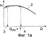
При работе насосной установки, в частности насосной установки, представляющей собой центробежный насос, которая состоит из насоса и из асинхронной машины, приводящей его в действие, часто необходимы сведения о ее рабочей точке. Рабочая точка работающей турбомашины, в частности, центробежного насоса, на ее характеристической кривой "интенсивность нагнетания/высота подачи" или, иными словами, на характеристической кривой Q-H характеризуется, в частности, его интенсивностью нагнетания, также именуемой ниже коэффициентом подачи. Существуют различные возможности для ее определения. Она может быть определена путем измерения интенсивности нагнетания или путем измерения давления. В последнем случае обычно измеряют разность давления между нагнетательной стороной и стороной всасывания насоса. Высоту подачи оценивают как соотношение между разностью давлений, плотностью и ускорением свободного падения. В том случае, когда нагнетаемой текучей средой является вода, разность давлений, равная 1 бару (105 Па), соответствует высоте подачи приблизительно 10 метров. Кроме того, рабочую точку центробежного насоса определяют по результатам электрических измерений, при этом выходную мощность электродвигателя вычисляют по результатам измерений тока и напряжения с учетом коэффициента полезного действия электродвигателя.When operating a pump installation, in particular a pump installation, which is a centrifugal pump, which consists of a pump and an asynchronous machine that drives it, information about its operating point is often necessary. The operating point of a working turbomachine, in particular a centrifugal pump, on its characteristic curve "discharge intensity / delivery height" or, in other words, on the characteristic curve QH is characterized, in particular, by its discharge intensity, also referred to below as the delivery coefficient. There are various possibilities for its definition. It can be determined by measuring the discharge rate or by measuring the pressure. In the latter case, the pressure difference between the discharge side and the suction side of the pump is usually measured. The feed height is estimated as the ratio between the pressure difference, density and gravity acceleration. In the case where the pumped fluid is water, a pressure difference of 1 bar (10 5 Pa) corresponds to a feed height of approximately 10 meters. In addition, the operating point of the centrifugal pump is determined by the results of electrical measurements, while the output of the electric motor is calculated from the results of measurements of current and voltage, taking into account the efficiency of the electric motor.
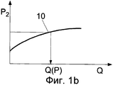
Для прямого измерения коэффициента подачи обычно требуется наличие магнитно-индукционных расходомеров. Косвенное определение коэффициента подачи арифметическими методами создает дополнительные трудности. Например, если коэффициент подачи получают исходя из значений на характеристической кривой "интенсивность нагнетания/высота подачи", то есть на характеристической кривой Q-H, представляющей собой график зависимости высоты Н подачи от интенсивности нагнетания, или на характеристической кривой "интенсивность нагнетания/мощность", то есть, на характеристической кривой Q-P, представляющей собой график зависимости мощности Р от интенсивности Q нагнетания, то это является трудным или даже невозможным в тех ситуациях, когда характеристическая кривая Q-H или характеристическая кривая Q-P является плоской или прерывисто растущей. Если коэффициент подачи нужно определять посредством измеренных значений давления по характеристической кривой Q-H центробежного насоса, то характеристическая кривая Q-H должна быть однозначной, то есть каждому значению Н должно быть точно назначено значение Q. На практике это условие часто не выполняется. Характеристические кривые Q-H являются либо слишком плоскими, либо даже неоднозначными. Та же самая проблема также возникает тогда, когда интенсивность Q нагнетания нужно определить посредством измеренной подводимой мощности по характеристической кривой "интенсивность нагнетания/мощность", то есть по характеристической кривой Q-P. Профиль характеристической кривой Q-P также часто является плоским или даже неоднозначным.For direct measurement of the feed coefficient, magnetic induction meters are usually required. Indirect determination of the feed coefficient by arithmetic methods creates additional difficulties. For example, if the feed coefficient is obtained based on the values on the characteristic curve "discharge intensity / height of delivery", that is, on the characteristic curve QH, which is a graph of the dependence of the height H of the feed on the intensity of discharge, or on the characteristic curve "discharge intensity / power", then is, on the characteristic curve QP, which is a graph of the dependence of the power P on the intensity Q of the discharge, this is difficult or even impossible in those situations where the characteristic the Q-H curve or the Q-P characteristic curve is flat or intermittently growing. If the flow coefficient needs to be determined by means of the measured pressure values from the characteristic curve Q-H of the centrifugal pump, then the characteristic curve Q-H must be unambiguous, that is, each value of H must be precisely assigned the value Q. In practice, this condition is often not fulfilled. The Q-H characteristic curves are either too flat or even ambiguous. The same problem also arises when the discharge intensity Q needs to be determined by the measured input power from the characteristic discharge intensity / power curve, that is, from the characteristic Q-P curve. The profile of the Q-P characteristic curve is also often flat or even ambiguous.
Из публикации заявки WO 2005/064167 A1 известно сочетание вышеупомянутых способов. Это влечет за собой значительные затраты с точки зрения измерений, поскольку необходимо измерять как перепад давления в насосе, так и электрическую мощность.A combination of the above methods is known from the publication of the application WO 2005/064167 A1. This entails significant costs in terms of measurements, since it is necessary to measure both the pressure drop in the pump and the electrical power.
На практике измерение электрической мощности, подводимой к сборочному узлу "электродвигатель/насос", влечет за собой определенные затраты. Измерение активной мощности производится в распределительном шкафу, для этого в нем требуется место, в частности, для измерения тока электродвигателя посредством трансформаторов тока и требует затрат при монтаже, который должен производиться электриками с особой квалификацией.In practice, measuring the electrical power supplied to the electric motor / pump assembly involves certain costs. Measurement of active power is carried out in a control cabinet, for this a place is required in it, in particular, for measuring the current of an electric motor by means of current transformers and requires installation costs, which must be carried out by electricians with special qualifications.
Устройство и способ определения мощности и/или крутящего момента асинхронных электродвигателей описаны в публикации заявки DD 258467 A1. На роторе асинхронного электродвигателя расположен бесконтактный датчик для обнаружения одного или большего количества импульсов за каждый оборот вала электродвигателя, и между сетью электроснабжения и микрокомпьютером подключен каскад схемы формирования импульсов для определения частоты синхронного вращения, исходя из частоты напряжения сети питания. Кроме того, это устройство содержит устройство для регистрации температуры электродвигателя и микрокомпьютер, в котором производят сбор всех данных измерений и их оценку для регулирования дальнейшей последовательности операций. Мощность и/или крутящий момент асинхронного электродвигателя определяют по времени одного или большего количества периодов с частотой вращения электродвигателя и одного или одного или большего количества периодов с частотой синхронного вращения. Мощность и/или крутящий момент асинхронного электродвигателя определяют путем подсчета количества импульсов от вала электродвигателя в пределах того промежутка времени, который известен как время срабатывания по управляющему входу (gate time), которое зафиксировано одним или большим количество периодов с частотой синхронного вращения. Для определения мощности и/или крутящего момента используют "уравнение Клосса (Kloss)". В способе требуется множество входных переменных, одной из которых также является частота синхронного вращения, которую определяют из переменных, полученных путем электрических измерений. Кроме того, в результаты должны быть введены поправки в зависимости от рабочей температуры электродвигателя, что вызывает необходимость определения путем измерений и сохранения требуемых поправочных коэффициентов для каждого типа электродвигателя заранее. Это устройство имеет сложную конфигурацию. Было выяснено, что этот способ является непригодным в промышленной практике. Особо существенным недостатком даже тогда, когда активную мощность, подводимую к асинхронному электродвигателю, традиционно измеряют посредством измерителей активной мощности и трансформаторов тока, является абсолютная необходимость монтажа такого устройства электриками с особой квалификацией.A device and method for determining the power and / or torque of induction motors are described in the publication of the application DD 258467 A1. A non-contact sensor is located on the rotor of the induction motor for detecting one or more pulses per revolution of the motor shaft, and a cascade of pulse shaping circuits is connected between the power supply network and the microcomputer to determine the frequency of synchronous rotation based on the frequency of the supply voltage. In addition, this device contains a device for recording the temperature of the electric motor and a microcomputer, in which all the measurement data is collected and evaluated to regulate the further sequence of operations. The power and / or torque of an induction motor is determined by the time of one or more periods with a frequency of rotation of the electric motor and one or one or more periods with a frequency of synchronous rotation. The power and / or torque of an induction motor is determined by counting the number of pulses from the motor shaft within the time interval known as the response time by the control input (gate time), which is fixed by one or more periods with a synchronous rotation frequency. To determine power and / or torque use the "Kloss equation (Kloss)". The method requires many input variables, one of which is also the frequency of synchronous rotation, which is determined from the variables obtained by electrical measurements. In addition, corrections should be made to the results depending on the operating temperature of the electric motor, which necessitates the determination of the required correction factors for each type of electric motor in advance by measuring and storing. This device has a complex configuration. It was found that this method is unsuitable in industrial practice. A particularly significant drawback even when the active power supplied to the induction motor is traditionally measured by means of active power meters and current transformers is the absolute necessity of installing such a device by electricians with special qualifications.
В публикации заявки DE 102006049440 A1 раскрыт способ обнаружения рабочего состояния насоса, в частности центробежного насоса или поршневого насоса, в насосной станции. Способ и соответствующее ему устройство служат для обнаружения неработоспособного рабочего состояния насоса, насосной станции и гидравлической установки по сравнению с сохраненным нормальным состоянием. Датчик давления регистрирует зависимость давления от времени в нагнетаемой среде. Вычисленное характеристическое значение характеризует пульсацию давления и/или профиля потока в интервале времени, в котором производят вычисления. Путем сравнения вычисленного характеристического значения, по меньшей мере, с одним из следующих значений: с заданным характеристическим значением или с ограниченным им интервалом характеристических значений, с заданным характеристическим значением или с ограниченным им интервалом характеристических значений, соответствующим надлежащему рабочему состоянию насоса, определяют рабочее состояние и выводят сведения о нем. В случае наличия диагностического прибора с подключенным датчиком давления и с дополнительным датчиком колебаний частоту вращения насоса определяют по сигналу от датчика давления и сведения о ней подают в датчик вибраций. Причины этого не раскрыты. Ни информация о частоте вращения, ни какие-либо другие переменные не свидетельствуют о рабочей точке на характеристической кривой Q-H или Q-P и/или о подводимой мощности, с которой работает насос. Этим способом указывают только лишь отклонения от заданных и сохраненных опорных значений.DE 102006049440 A1 discloses a method for detecting the operating state of a pump, in particular a centrifugal pump or a piston pump, in a pumping station. The method and the corresponding device serve to detect the inoperative operating state of the pump, pumping station and hydraulic unit compared to the stored normal state. The pressure sensor registers the dependence of pressure on time in the pumped medium. The calculated characteristic value characterizes the pulsation of the pressure and / or flow profile in the time interval in which the calculations are performed. By comparing the calculated characteristic value with at least one of the following values: with a given characteristic value or with a limited range of characteristic values, with a given characteristic value or with a limited range of characteristic values corresponding to the proper operating state of the pump, the operating state is determined and display information about him. If there is a diagnostic tool with a connected pressure sensor and with an additional vibration sensor, the pump speed is determined by a signal from the pressure sensor and information about it is supplied to the vibration sensor. The reasons for this are not disclosed. Neither speed information nor any other variables indicate the operating point on the Q-H or Q-P characteristic curve and / or the input power with which the pump operates. In this way, only deviations from the set and stored reference values are indicated.
В публикации заявки DE 19618462 A1 раскрыт еще один способ и еще одно устройство для определения косвенного параметра, характеризующего мощность устройства преобразования энергии, например, объема или массы потока, протекающего через центробежный насос с приводом от электродвигателя, в котором зависящую от рабочего состояния истинную переменную определяют непрерывно.DE 19618462 A1 discloses yet another method and another device for determining an indirect parameter characterizing the power of an energy conversion device, for example, the volume or mass of a stream flowing through a centrifugal pump driven by an electric motor, in which the true variable depending on the operating state is determined continuously.
Задачей, лежащей в основе настоящего изобретение, является создание способа и устройства, посредством которых можно реализовать менее сложное, надежное определение и, в необходимых случаях, контроль текущей рабочей точки рабочей машины и/или асинхронного электродвигателя, приводящего ее в действие.The objective underlying the present invention is the creation of a method and device by which it is possible to implement a less complex, reliable determination and, if necessary, control the current operating point of the working machine and / or asynchronous electric motor that drives it.
Согласно настоящему изобретению эта задача реализована посредством того, что рабочую точку определяют без использования переменных приводного асинхронного электродвигателя, получаемых путем электрических измерений, и посредством того, что частоту, линейно пропорциональную звуку от вращения рабочей машины, определяют по переменной, получаемой путем механических измерений, а именно по давлению, перепаду давления, силе, вибрации, шуму, распространяющемуся в твердом теле, или шуму, распространяющемуся по воздуху, посредством анализа сигнала, в частности частотного анализа, по результатам которого определяют частоту вращения механизма привода, а рабочую точку определяют по вызванной пробуксовкой зависимости "частота вращения/крутящий момент" асинхронного электродвигателя.According to the present invention, this task is realized by means of the fact that the operating point is determined without using variables of the drive induction motor obtained by electrical measurements, and by the fact that the frequency linearly proportional to the sound from the rotation of the working machine is determined by the variable obtained by mechanical measurements, and namely, pressure, pressure drop, force, vibration, noise propagating in a solid, or noise propagating through air through analysis of ala, in particular frequency response analysis, the results of which determine the speed of the drive mechanism, and the operating point is determined by the slip caused by dependence "speed / torque" asynchronous motor.
Согласно настоящему изобретению рабочую точку определяют без использования переменных, получаемых путем электрических измерений. Вместо этого частоту, линейно пропорциональную звуку от вращения рабочей машины, в частности, частоту звука от вращения рабочей машины, определяют, исходя из профиля сигнала измеренной переменной, полученной путем механических измерений. Для простоты ее именуют ниже частотой звука от вращения. Ее получают из произведения частоты вращения на количество структур, возбуждающих колебания, осциллирующего или вращающегося элемента, в частности, на количество лопастей крыльчатки насоса. Исходя из нее, определяют частоту вращения механизма привода и при помощи сохраненных данных определяют мощность, подводимую к рабочей машине, также именуемую ниже выходной мощностью на валу, и/или ее коэффициент подачи. Пригодными переменными, получаемыми путем механических измерений, являются давление, в частности давление на нагнетательной стороне центробежного насоса, перепад давления, в частности перепад давления между стороной всасывания и нагнетательной стороной центробежного насоса, сила, вибрация, шум, распространяющийся в твердом теле, или шум, распространяющийся по воздуху, в частности, шум центробежного насоса или шум, вызванный центробежным насосом, и т.п. Рабочая точка рабочей машины может быть определена по одной переменной, получаемой путем иных измерений, чем электрические. Способ определения рабочей точки согласно настоящему изобретению, в котором обходятся без переменных, получаемых путем электрических измерений, является сравнительно рентабельным и может быть реализован при самых скромных возможных затратах с точки зрения монтажа.According to the present invention, the operating point is determined without using variables obtained by electrical measurements. Instead, the frequency linearly proportional to the sound from the rotation of the working machine, in particular, the frequency of sound from the rotation of the working machine, is determined based on the signal profile of the measured variable obtained by mechanical measurements. For simplicity, it is referred to below as the frequency of sound from rotation. It is obtained from the product of the rotational speed by the number of structures, exciting oscillations, of an oscillating or rotating element, in particular, by the number of pump impeller blades. Based on it, determine the frequency of rotation of the drive mechanism and using the stored data determine the power supplied to the working machine, also referred to below as the output power on the shaft, and / or its feed coefficient. Suitable variables obtained by mechanical measurements are pressure, in particular pressure on the discharge side of the centrifugal pump, pressure drop, in particular pressure drop between the suction side and the discharge side of the centrifugal pump, force, vibration, noise propagating in the solid, or noise, propagating through the air, in particular the noise of a centrifugal pump or the noise caused by a centrifugal pump, etc. The operating point of the working machine can be determined by one variable obtained by other measurements than electrical. The method for determining the operating point according to the present invention, which dispenses with variables obtained by electrical measurements, is relatively cost-effective and can be implemented at the most modest possible cost from the point of view of installation.
В усовершенствовании из настоящего изобретения мощность, подводимую к рабочей машине, определяют посредством следующих операций:In an improvement of the present invention, the power supplied to the working machine is determined by the following operations:
- операции определения характеристической кривой "частота вращения/крутящий момент" электродвигателя, в частности, посредством заданных параметров электродвигателя, а именно расчетной мощности и расчетной частоты вращения, а при необходимости, частоты синхронного вращения, предельного перегрузочного момента, предельной перегрузочной частоты вращения или предельной перегрузочной пробуксовки;- the operation of determining the characteristic curve "speed / torque" of the electric motor, in particular by means of the specified parameters of the electric motor, namely the rated power and the calculated speed, and, if necessary, the frequency of synchronous rotation, maximum overload torque, maximum overload speed or maximum overload slippage;
- операции определения подводимой мощности или крутящего момента электродвигателя, исходя из определенной частоты вращения привода и характеристической кривой "частота вращения/крутящий момент" электродвигателя.- the operation of determining the input power or torque of the electric motor, based on a certain speed of the drive and the characteristic curve "speed / torque" of the electric motor.
Необходимые параметры для определения характеристической кривой "частота вращения/крутящий момент" электродвигателя получают из данных из таблички с паспортными техническими данными асинхронного электродвигателя, например, расчетный или номинальный крутящий момент МN получают из приведенного ниже отношения расчетной мощности Р2N асинхронного электродвигателя к номинальной частоте nN вращения:The necessary parameters for determining the characteristic curve "speed / torque" of the electric motor are obtained from the data from the nameplate with the technical data of the asynchronous electric motor, for example, the calculated or rated torque M N is obtained from the ratio of the rated power P 2N of the asynchronous electric motor to the rated frequency n N rotation:

Если предельный перегрузочный момент Мk и/или предельная перегрузочная пробуксовка sk асинхронного электродвигателя являются известными/является известным (известной), то характеристическая кривая "частота вращения/крутящий момент", то есть характеристическая кривая n-M, асинхронного электродвигателя отображается посредством уравнения Клосса (Kloss):If the maximum overload torque M k and / or the maximum overload slip s k of the induction motor are known / known (known), then the characteristic curve "speed / torque", that is, the characteristic curve nM, of the asynchronous electric motor is displayed using the Kloss equation (Kloss ):

Поскольку пробуксовка s асинхронного электродвигателя равна Since the slippage s of an induction motor is

то профиль характеристической кривой n-M получают в следующем виде:then the profile of the characteristic curve n-M is obtained in the following form:

а предельная перегрузочная частота nк вращения равнаand the maximum overload frequency n to rotation is

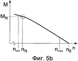
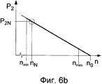
В альтернативном варианте в рабочем диапазоне рабочей машины характеристическая кривая "частота вращения/крутящий момент" асинхронного электродвигателя может быть аппроксимирована прямой линией, проходящей через точку (МN; nN), заданную номинальным крутящим моментом МN на номинальной частоте nN вращения, и точку (М=0; n0), заданную крутящим моментом М, равным нулю, при частоте посинхронного вращения. Это тогда приводит к приведенной ниже аппроксимированной или упрощенной характеристической кривой "частота вращения/крутящий момент", то есть к характеристической кривой n-М, асинхронного электродвигателя, профиль которой описывается следующей формулой:Alternatively, in the operating range of the working machine, the characteristic “speed / torque” curve of the induction motor can be approximated by a straight line passing through the point (M N ; n N ) specified by the rated torque M N at the rated speed n N of rotation, and a point (M = 0; n 0 ) defined by a torque M equal to zero at a synchronous rotation frequency. This then leads to the approximated or simplified characteristic curve "speed / torque", that is, to the characteristic curve n-M, an induction motor, the profile of which is described by the following formula:

Мощность, подводимую к рабочей машине, определяют из ранее определенной частоты вращения привода, также именуемой ниже частотой вращения вала, и из характеристической кривой "частота вращения/крутящий момент", то есть характеристической кривой n-М, электродвигателя. Это соотношение между выходной мощностью P2 на валу, крутящим моментом М и частотой n вращения задано следующим уравнением:The power supplied to the working machine is determined from a previously determined rotational speed of the drive, also referred to below as the rotational speed of the shaft, and from the characteristic curve "rotational speed / torque", that is, the characteristic curve n-M, of the electric motor. This ratio between the output power P 2 on the shaft, the torque M and the rotation frequency n is given by the following equation:
![]()
![]()
Согласно настоящему изобретению определяют рабочую точку рабочей машины, в частности насоса, характеризующуюся подводимой к ней мощностью. Это обеспечивается посредством существующих датчиков, расположенных на насосе.According to the present invention, the operating point of a working machine, in particular a pump, characterized by the power supplied to it, is determined. This is ensured by existing sensors located on the pump.
В случае насоса, в частности, центробежного насоса как рабочей машины целесообразное усовершенствование предусматривает определение его коэффициента подачи по частоте вращения его привода. Частоту звука от вращения определяют из профиля сигнала от переменной, получаемой путем иных измерений, чем электрические, посредством анализа сигнала, в частности частотного анализа, например, методом быстрого преобразования Фурье (FFT) или автокорреляции. Исходя из нее, определяют частоту вращения привода. В примере центробежного насоса в качестве рабочей машины частоту вращения получают как отношение частоты fD звука от вращения к количеству z лопастей рабочего колеса:In the case of a pump, in particular, a centrifugal pump as a working machine, a reasonable improvement involves the determination of its feed coefficient by the frequency of rotation of its drive. The sound frequency from rotation is determined from the signal profile of a variable obtained by other measurements than electrical ones, by analyzing the signal, in particular frequency analysis, for example, by the Fast Fourier Transform (FFT) method or autocorrelation. Based on it, determine the speed of the drive. In the example of a centrifugal pump as a working machine, the rotational speed is obtained as the ratio of the frequency f D of sound from rotation to the number z of impeller blades:
![]()
![]()
Выходная мощность на валу и/или коэффициент подачи могут быть определены из частоты вращения посредством зависимости "частота вращения/крутящий момент". Обходятся без измерения электрических переменных, результатом чего является значительное сокращение затрат на выполнение определения рабочей точки по сравнению с традиционным определением рабочей точки на основании измерения активной электрической мощности. Аналогичным образом имеет место значительный выигрыш по затратам по сравнению с прямым измерением коэффициента подачи, например, посредством технологии ультразвукового измерения протекающего потока или технологии магнитно-индукционного измерения протекающего потока, поскольку используемые переменные, получаемые путем механических измерений, а именно давление, перепад давления, сила, вибрация, шум, распространяющийся в твердом теле, или шум, распространяющийся по воздуху, регистрируют и обрабатывают более благоприятным образом.The output power on the shaft and / or the feed coefficient can be determined from the rotational speed by means of the “rotational speed / torque” relationship. Without the measurement of electrical variables, the result is a significant reduction in the cost of determining the operating point compared to the traditional definition of the operating point based on the measurement of active electric power. Likewise, there is a significant cost advantage compared to directly measuring the flow coefficient, for example, by means of ultrasonic flow measurement technology or magnetic induction measurement of flow flow, since the variables used are obtained by mechanical measurements, namely pressure, differential pressure, force , vibration, noise propagating in a solid, or noise propagating through air, is recorded and processed in a more favorable manner.
Доказана целесообразность определения коэффициента подачи насоса, исходя из подводимой мощности или из выходной мощности на валу, определенной по частоте вращения привода. Во-первых, как описано выше, выходную мощность на валу насоса определяют согласно формуле (7), исходя из частоты вращения привода или частоты вращения вала, при помощи известной характеристической кривой n-М или получаемой от нее характеристической кривой n-Р. При последующей операции определяют коэффициент Q подачи насоса, исходя из выходной мощности на валу, посредством сохраненной характеристической кривой Q-P.The expediency of determining the pump flow coefficient based on the input power or on the output power on the shaft, determined by the rotational speed of the drive, is proved. Firstly, as described above, the output power on the pump shaft is determined according to formula (7), based on the rotational speed of the drive or the rotational speed of the shaft, using the known characteristic curve n-M or the characteristic curve n-P obtained from it. In a subsequent operation, the pump supply coefficient Q is determined based on the output power on the shaft using the stored characteristic curve Q-P.
Коэффициент подачи насоса может быть определен, исходя из параметров электродвигателя, которые описывают характеристическую кривую "частота вращения/крутящий момент" электродвигателя, а также из параметров насоса, которые описывают характеристическую кривую "интенсивность нагнетания/мощность", и из частоты вращения привода. Характеристическая кривая Q-P может быть описана, например, в виде таблицы параметров с множеством опорных точек (с _1 по _i). При определении рабочей точки в способе используют такую предварительно сохраненную таблицу для определения коэффициента подачи по выходной мощности на валу:The pump coefficient can be determined based on the parameters of the electric motor, which describe the characteristic curve "speed / torque" of the electric motor, as well as the parameters of the pump, which describe the characteristic curve "pumping intensity / power", and from the speed of the drive. The characteristic curve Q-P can be described, for example, in the form of a table of parameters with many reference points (from _1 to _i). When determining the operating point in the method, such a previously saved table is used to determine the feed coefficient by the output power on the shaft:
![]()
![]()
![]()
![]()
![]()
![]()
![]()
![]()
Эта таблица может дополнительно содержать опорные точки для соответствующей частоты вращения, посредством чего становится возможным определять интенсивность нагнетания непосредственно по определенной частоте вращения.This table may further comprise reference points for the corresponding speed of rotation, whereby it becomes possible to determine the discharge rate directly from the determined speed.
В частности, для дальнейшего усовершенствования способа в областях неоднозначности характеристической кривой Q-P для определения коэффициента подачи насоса может дополнительно использоваться высота подачи или перепад давления. Кроме того, для определения рабочей точки могут учитываться обе характеристические кривые: характеристическая кривая Q-P и характеристическая кривая Q-H. Для этого могут быть сохранены, например, значения отношения Р2/Н:In particular, to further improve the method in the areas of ambiguity of the characteristic curve QP, a delivery height or a pressure differential can be additionally used to determine the pump flow coefficient. In addition, to determine the operating point, both characteristic curves can be taken into account: the characteristic curve QP and the characteristic curve QH. For this, for example, the values of the ratio P 2 / H can be stored:
![]()
![]()
![]()
![]()
![]()
![]()
![]()
![]()
![]()
![]()
![]()
![]()
![]()
![]()
![]()
![]()
![]()
![]()
![]()
![]()
![]()
![]()
![]()
![]()
Также имеется предусмотренная возможность определения коэффициента подачи центробежного насоса по характеристической кривой, которая отображает зависимость коэффициента подачи насоса от изменения частоты вращения в зависимости от нагрузки. Такая характеристическая кривая "частота вращения/интенсивность нагнетания" может быть вычислена по характеристической кривой "частота вращения/крутящий момент" электродвигателя в соответствии с характеристической кривой "интенсивность нагнетания/мощность":It is also provided for the possibility of determining the feed coefficient of a centrifugal pump from a characteristic curve that displays the dependence of the pump coefficient on the change in speed depending on the load. Such a characteristic curve "speed / discharge intensity" can be calculated from the characteristic curve "speed / torque" of the electric motor in accordance with the characteristic curve "discharge intensity / power":
![]()
![]()
![]()
![]()
![]()
![]()
![]()
![]()
![]()
![]()
![]()
![]()
![]()
![]()
![]()
![]()
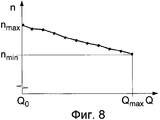
В альтернативном варианте, даже не имея сведений о характеристических кривых Q-P и Q-H, характеристическая кривая для определения коэффициента подачи может быть определена, исходя из изменения частоты вращения в зависимости от нагрузки. Для этого соответствующая рабочая частота вращения может быть определена и сохранена при пробном запуске насоса, который производят, например, во время ввода в эксплуатацию, во множестве рабочих точек с известным коэффициентом подачи, в том числе, например, при Q0, то есть при интенсивности нагнетания, равной нулю, и при Qmax, то есть при максимальной допустимой интенсивности нагнетания. В результате этого получают таблицу параметров, представленную ниже в общем виде:Alternatively, even without knowledge of the QP and QH characteristic curves, the characteristic curve for determining the feed rate can be determined based on a change in rotational speed depending on the load. To do this, the corresponding operating speed can be determined and stored during a test run of the pump, which is produced, for example, during commissioning, at a number of operating points with a known feed coefficient, including, for example, at Q 0 , i.e. at intensity discharge, equal to zero, and at Qmax, that is, at the maximum permissible discharge intensity. As a result of this, a parameter table is obtained, presented below in a general form:
![]()
![]()
![]()
![]()
![]()
![]()
![]()
![]()
В альтернативном варианте значения частоты вращения могут быть определены и сохранены путем "обучения" во время штатного режима эксплуатации насоса. Таким образом, в центробежном насосе с характеристической кривой Q-P, в которой Р растет строго монотонно прямо пропорционально Q, как, например, в большинстве насосов с радиальным колесом, самая высокая частота вращения, которая имеет место, поставлена в соответствие самой низкой подводимой мощности, которая имеет место, и наименьшей интенсивности нагнетания, если это уместно, с закрытым клапаном, то есть интенсивности нагнетания, равной нулю. Если частота вращения во время работы снова уменьшается, то это означает, что интенсивность нагнетания увеличивается. Таким образом, за период эксплуатации центробежного насоса изучен рабочий диапазон в пределах от (Qmin '; nmax ') до (Qmax '; nmin '), что имеет место в исследованном периоде эксплуатации, без измерения конкретных значений Q или их определения с этой целью. Узнанные предельные значения используют для классификации текущей интенсивности нагнетания центробежного насоса в каждом случае между минимальной интенсивностью Qmin ' нагнетания и максимальной интенсивностью Qmax ' нагнетания, которые имеют место в течение исследованного периода эксплуатации.Alternatively, the speed values can be determined and stored by “learning” during normal operation of the pump. Thus, in a centrifugal pump with a characteristic curve QP, in which P grows strictly monotonically in direct proportion to Q, as, for example, in most pumps with a radial wheel, the highest speed that takes place is aligned with the lowest input power, which takes place, and the lowest discharge rate, if appropriate, with the valve closed, that is, the discharge rate is zero. If the rotational speed decreases again during operation, this means that the discharge rate increases. Thus, during the operation period of the centrifugal pump, the operating range was studied ranging from (Q min ' ; n max ' ) to (Q max ' ; n min ' ), which takes place in the studied period of operation, without measuring specific Q values or determining them to this end. The recognized limit values are used to classify the current pumping intensity of the centrifugal pump in each case between the minimum pumping intensity Q min ' and the maximum pumping intensity Q max ' that occur during the period of operation studied.
Согласно этому усовершенствованию также используют зависимость "частота вращения/крутящий момент" асинхронного электродвигателя. В этом случае в настоящем изобретении используют сведения о том, что это вызывает поддающееся оценке изменение частоты вращения в интервале значений интенсивности нагнетания. Посредством такой характеристической кривой, которая обычно не является документированной для насоса, коэффициент подачи центробежного насоса может быть определен непосредственно по частоте вращения.According to this improvement, the rotation frequency / torque relationship of an induction motor is also used. In this case, the present invention uses information that it causes a measurable change in speed in the range of discharge intensities. By means of a characteristic curve that is not usually documented for a pump, the flow coefficient of a centrifugal pump can be determined directly from the speed.
Способ, согласно которому частоту вращения привода или частоту вращения вала для определения рабочей точки насоса определяют по измеренным значениям от одного или от большего количества датчиков давления, в частности, центробежного насоса, является особенно надежным. В этом случае целесообразно, чтобы датчики давления были пригодными для динамического измерения значений давления, в частности, значений пульсирующего давления. Следовательно, рабочую точку насоса, в частности центробежного насоса, которая характеризуется выходной мощностью на валу и/или коэффициентом подачи, определяют исключительно по измеренным значениям одного или большего количества датчиков давления. Один или большее количество датчиков давления на центробежном насосе используют для регистрации давления всасывания и/или предельного давления центробежного насоса. Несмотря на то, что датчики давления предусмотрены для измерения значений статического давления, они также являются наиболее подходящими для динамического измерения значений давления. Проверки показали, что стандартные датчики давления обеспечивают динамическую регистрацию значений давления, и не имеют затуханий до полосы частот приблизительно 1 кГц. Такие датчики давления способны регистрировать пульсирующие значения давления, имеющие место в центробежном насосе. В способе согласно настоящему изобретению достигается точность, достаточная для многих областей применения, когда на нагнетательной стороне насоса используется всего лишь один датчик давления. Кроме того, датчик давления может быть предусмотрен на стороне всасывания насоса. Также предусмотрена возможность оценки перепада давления в насосе между нагнетательной стороной и стороной всасывания насоса, получаемой посредством датчика перепада давления. На основании способа согласно настоящему изобретению рабочая точка может быть определена рентабельно, без использования дополнительных датчиков, исключительно по сигналам от одного или от большего количества датчиков давления.The method according to which the rotational speed of the drive or the rotational speed of the shaft for determining the operating point of the pump is determined from the measured values from one or more pressure sensors, in particular a centrifugal pump, is particularly reliable. In this case, it is advisable that the pressure sensors are suitable for dynamically measuring pressure values, in particular pulsating pressure values. Therefore, the operating point of the pump, in particular the centrifugal pump, which is characterized by the output power on the shaft and / or the delivery coefficient, is determined solely from the measured values of one or more pressure sensors. One or more pressure sensors on the centrifugal pump is used to record the suction pressure and / or pressure limit of the centrifugal pump. Although pressure sensors are designed to measure static pressure values, they are also most suitable for dynamically measuring pressure values. Inspections have shown that standard pressure sensors provide dynamic recording of pressure values, and do not have attenuation up to a frequency band of approximately 1 kHz. Such pressure sensors are capable of detecting pulsating pressure values occurring in a centrifugal pump. In the method according to the present invention, an accuracy sufficient for many applications is achieved when only one pressure sensor is used on the discharge side of the pump. In addition, a pressure sensor may be provided on the suction side of the pump. It is also possible to evaluate the differential pressure in the pump between the discharge side and the suction side of the pump obtained by the differential pressure sensor. Based on the method according to the present invention, the operating point can be determined cost-effectively, without the use of additional sensors, solely from signals from one or more pressure sensors.
В другом усовершенствовании частоту вращения привода определяют по измеренным значениям от одного или от большего количества датчиков шума, распространяющегося в твердом теле, и/или шума, распространяющегося по воздуху, для определения рабочей точки рабочей машины и/или асинхронного электродвигателя, приводящего ее в действие. В этом случае датчики шума, распространяющегося в твердом теле, и/или шума, распространяющегося по воздуху, могут быть расположены на рабочей машине и/или на асинхронном электродвигателе, приводящем ее в действие. Датчики также могут быть расположены вблизи рабочей машины. В любом случае частоту, которая является линейно пропорциональной звуку от вращения рабочей машины и по которой определяют частоту вращения рабочей машины, регистрируют по сигналам от датчиков, которые регистрируют переменные, получаемые путем механических измерений. И, исходя из нее, определяют рабочую точку с использованием зависимости "частота вращения/крутящий момент" асинхронного электродвигателя.In another improvement, the rotational speed of the drive is determined from measured values from one or more sensors of noise propagating in a solid and / or noise propagating through air to determine the operating point of a working machine and / or an asynchronous electric motor driving it. In this case, the sensors of noise propagating in a solid and / or noise propagating through air can be located on a working machine and / or on an induction motor that drives it. Sensors can also be located near the working machine. In any case, a frequency that is linearly proportional to the sound from the rotation of the working machine and by which the speed of the working machine is determined is recorded from signals from sensors that record variables obtained by mechanical measurements. And, based on it, determine the operating point using the dependence "speed / torque" of an induction motor.
Согласно настоящему изобретению может быть осуществлен текущий контроль того, находится ли определенная рабочая точка внутри заданного допустимого диапазона или вне его. На основании того, что рабочая точка находится вне заданного диапазона, обнаруживают неработоспособное рабочее состояние, в частности, перегрузку или недостаточную нагрузку рабочей машины и/или асинхронного электродвигателя. Например, посредством текущего контроля или оценки мощности, подводимой к центробежному насосу, может быть сделан вывод о режиме работы с неполной нагрузкой или об оптимальном режиме работы. Если в качестве измеряемой переменной используется шум, распространяющийся в твердом теле, или шум, распространяющийся по воздуху, то также может быть обнаружен сухой ход центробежного насоса. Проверки показали, что обнаружение перегрузки асинхронного электродвигателя согласно настоящему изобретению функционирует достоверно и надежно. Если подводимая мощность увеличивается по сравнению с документированной и параметризованной подводимой мощностью, то может быть сделан вывод о перегрузке насоса или электродвигателя. Общеизвестно, что пониженное напряжение на стороне подачи электропитания также может являться причиной предположительно увеличенной подводимой мощности, что, следовательно, приводит к росту пробуксовки. В этом случае диагностика перегрузки для установки, состоящей из насоса и электродвигателя, тем не менее, является правильной, поскольку в случае пониженного напряжения и, следовательно, увеличенной пробуксовки растет потребление тока электродвигателем. Это влияние является существенным тогда, когда напряжение сети выходит за пределы допустимых значений и, например, снижается более чем на 10% от номинального напряжения. В этом случае будет сделан вывод о том, что при номинальной частоте n вращения, равной nN, номинальная мощность P2=P2N, даже несмотря на то, что фактическая подводимая мощность является меньшей, чем номинальная мощность. Если частота вращения уменьшается еще сильнее, то есть n<nN, то делают вывод о перегрузке насоса или электродвигателя, что является правильным, поскольку растут потери, пропорциональные току, в частности, потери в роторе асинхронного электродвигателя, которые, следовательно, вносят вклад в перегрев электродвигателя.According to the present invention, it can be monitored whether a specific operating point is within or outside a given allowable range. Based on the fact that the operating point is outside the specified range, an inoperative operating state is detected, in particular, an overload or insufficient load of the working machine and / or asynchronous motor. For example, by monitoring or evaluating the power supplied to a centrifugal pump, it can be concluded that the operating mode is under partial load or the optimal operating mode. If noise propagating in a solid or noise propagating through air is used as the measured variable, then the dry running of the centrifugal pump can also be detected. Inspections have shown that the detection of overload of an induction motor according to the present invention operates reliably and reliably. If the input power increases compared to the documented and parameterized input power, then a conclusion can be drawn about the overload of the pump or electric motor. It is well known that undervoltage on the supply side can also be the reason for the supposedly increased input power, which, consequently, leads to an increase in slippage. In this case, the overload diagnosis for the installation, consisting of a pump and an electric motor, however, is correct, since in the case of a low voltage and, consequently, increased slippage, the current consumption of the electric motor increases. This effect is significant when the mains voltage goes beyond the permissible values and, for example, decreases by more than 10% of the rated voltage. In this case, it will be concluded that at a rated speed n of rotation equal to n N , the rated power P 2 = P 2N , even though the actual input power is less than the rated power. If the rotation speed decreases even more, that is, n <n N , then we conclude that the pump or electric motor is overloaded, which is correct because losses are proportional to the current, in particular, losses in the rotor of the induction motor, which, therefore, contribute to motor overheating.
Согласно настоящему изобретению в устройстве для определения рабочей точки рабочей машины и/или асинхронного электродвигателя, приводящего ее в действие, в котором в упомянутое устройство подают один или большее количество входных сигналов для регистрации измеряемых переменных, зависящих от рабочей точки, предоставлена возможность, в силу которой устройство имеет хранилище данных для хранения технических данных о рабочей машине и/или об асинхронном электродвигателе, приводящем ее в действие, и определяет частоту, линейно пропорциональную звуку от вращения рабочей машины, исходя из переменной, получаемой путем механических измерений, а именно давления, перепада давления, силы, вибрации, шума, распространяющегося в твердом теле, или шума, распространяющегося по воздуху, посредством анализа сигнала, в частности частотного анализа, по ней определяет частоту вращения механизма привода и, исходя из нее, используя вызванную пробуксовкой зависимость "частота вращения/крутящий момент" асинхронного электродвигателя, определяет рабочую точку и, при необходимости, осуществляет текущий контроль рабочей точки по переменным, получаемым путем иных измерений, чем электрические измерения, без использования переменных приводного асинхронного электродвигателя, получаемых путем электрических измерений.According to the present invention, in an apparatus for determining an operating point of a working machine and / or an asynchronous electric motor driving it, in which one or more input signals are supplied to said device for recording measured variables depending on the operating point, it is possible to the device has a data warehouse for storing technical data about the working machine and / or the asynchronous electric motor that drives it, and determines the frequency, linearly proportional the sound from the rotation of the working machine, based on a variable obtained by mechanical measurements, namely pressure, pressure drop, force, vibration, noise propagating in a solid, or noise propagating through air, through signal analysis, in particular frequency analysis, it determines the frequency of rotation of the drive mechanism and, on the basis of it, using the dependence "speed / torque" of the induction motor caused by slipping, determines the operating point and, if necessary, t current control of the operating point by variables obtained by measurements other than electrical measurements, without using variables of the drive induction motor obtained by electrical measurements.
Хранилище данных может обеспечивать хранение параметров электродвигателя, которые описывают зависимость "частота вращения/крутящий момент" асинхронного электродвигателя и/или иных технических данных об устройстве, которым является рабочая машина. Доступ к ним для определения рабочей точки может осуществляться во время работы рабочей машины. Отсутствует необходимость в регистрации устройством переменных, получаемых путем электрических измерений. Устройство может определять рабочую точку рабочей машины, исходя из одного измерительного сигнала, например, сигнала от датчика давления.The data warehouse can provide storage of motor parameters that describe the dependence "speed / torque" of an induction motor and / or other technical data about the device, which is a working machine. Access to them to determine the operating point can be carried out during operation of the working machine. There is no need for the device to register variables obtained by electrical measurements. The device can determine the operating point of the working machine, based on one measuring signal, for example, a signal from a pressure sensor.
Согласно усовершенствованию из настоящего изобретения устройство определяет мощность, подводимую к рабочей машине, посредством следующих операций:According to an improvement of the present invention, the device determines the power supplied to the working machine by the following operations:
- операции определения характеристической кривой "частота вращения/крутящий момент" электродвигателя, в частности, посредством заданных параметров электродвигателя, а именно расчетной мощности и расчетной частоты вращения, а при необходимости, частоты синхронного вращения, предельного перегрузочного момента, предельной перегрузочной частоты вращения или предельной перегрузочной пробуксовки;- the operation of determining the characteristic curve "speed / torque" of the electric motor, in particular by means of the specified parameters of the electric motor, namely the rated power and the calculated speed, and, if necessary, the frequency of synchronous rotation, maximum overload torque, maximum overload speed or maximum overload slippage;
- операции определения подводимой мощности или крутящего момента электродвигателя, исходя из частоты вращения привода и характеристической кривой "частота вращения/крутящий момент" электродвигателя.- operations for determining the input power or torque of the electric motor, based on the frequency of rotation of the drive and the characteristic curve "frequency of rotation / torque" of the electric motor.
В насосе, в частности в центробежном насосе как рабочей машине, предусмотрена возможность определения коэффициента подачи насоса, исходя из частоты вращения привода. В этом насосе регистрируют только лишь переменные, получаемые путем механических измерений. Частоту вращения привода или вала насоса определяют, исходя из определенной частоты звука от вращения.In the pump, in particular in the centrifugal pump as a working machine, it is possible to determine the pump flow rate based on the speed of the drive. Only variables obtained by mechanical measurements are recorded in this pump. The speed of the drive or pump shaft is determined based on a certain sound frequency from rotation.
Имеет место значительный выигрыш по затратам по сравнению с прямым измерением коэффициента подачи, например, посредством технологии ультразвукового измерения протекающего потока или технологии магнитно-индукционного измерения протекающего потока. Издержки и затраты также минимизированы по сравнению с определением коэффициента подачи на основании измерения активной электрической мощности.There is a significant cost benefit compared to directly measuring the flow coefficient, for example, through ultrasonic flow measurement technology or magnetic induction measurement technology. Costs and costs are also minimized compared to determining the feed rate based on a measurement of active electrical power.
Устройство может быть расположено на насосе, на электродвигателе его привода или вблизи него, и/или может быть объединено с насосом или с электродвигателем его привода.The device can be located on the pump, on the electric motor of its drive or near it, and / or can be combined with the pump or with the electric motor of its drive.
Устройство может определять коэффициент подачи насоса, в частности центробежного насоса, исходя из подводимой мощности или выходной мощности на валу, определенной по частоте вращения привода или по частоте вращения вала.The device can determine the delivery coefficient of the pump, in particular the centrifugal pump, based on the input power or the output power on the shaft, determined by the rotational speed of the drive or the rotational speed of the shaft.
Доказана целесообразность определения устройством коэффициента подачи насоса, в частности центробежного насоса, по параметрам электродвигателя, которые описывают характеристическую кривую "частота вращения/крутящий момент" электродвигателя, а также по параметрам насоса, которые описывают характеристическую кривую "интенсивность нагнетания/мощность", и по частоте вращения привода или по частоте вращения вала.It has been proved that the device determines the pump delivery coefficient, in particular of a centrifugal pump, by the parameters of the electric motor, which describe the characteristic curve "speed / torque" of the electric motor, and also by the parameters of the pump, which describe the characteristic curve "discharge intensity / power", and frequency drive rotation or shaft speed.
Для устройства предусмотрена возможность легко определять коэффициент подачи насоса, в частности центробежного насоса, непосредственно по характеристической кривой, которая отображает зависимость коэффициента подачи насоса от изменения частоты вращения в зависимости от нагрузки. Такая характеристическая кривая может быть определена посредством пробных запусков и сохранена в хранилище данных для того, чтобы она могла быть извлечена во время работы центробежного насоса. Тем не менее, здесь используется зависимость "частота вращения/крутящий момент" асинхронного электродвигателя, что приводит к изменению частоты вращения в интервале значений интенсивности нагнетания. Рабочая точка, характеризующаяся мощностью, подводимой к рабочей машине, и/или ее коэффициентом подачи, может быть определена по ней особо простым способом.It is possible for the device to easily determine the pump coefficient, in particular of a centrifugal pump, directly from the characteristic curve, which displays the dependence of the pump coefficient on the change in speed depending on the load. Such a characteristic curve can be determined by trial runs and stored in a data warehouse so that it can be retrieved during operation of the centrifugal pump. However, here we use the dependence "speed / torque" of an asynchronous electric motor, which leads to a change in the frequency of rotation in the range of discharge intensities. The operating point, characterized by the power supplied to the working machine and / or its feed coefficient, can be determined from it in a particularly simple way.
Идеальным вариантом является тот, если устройство имеет, по меньшей мере, одно соединение для датчика давления и определяет частоту вращения привода или частоту вращения вала, исходя из измеренных значений подсоединенного датчика давления для определения рабочей точки рабочей машины. Датчики давления для регистрации статических значений давления также способны регистрировать динамические флуктуации давления. Во всяком случае, такие датчики давления установлены на многих насосах, в частности, для регистрации предельного давления в них. Обычные устройства для регистрации сигналов от датчиков давления посредством аналоговых устройств ввода, например, в программируемых средствах управления хранилищами или в преобразователях частоты, обычно обеспечивают возможность использования отфильтрованных, то есть динамически демпфированных измеренных значений. Такие устройства ввода являются слишком медленными и нечувствительными для регистрации динамической составляющей соответствующего сигнала давления согласно настоящему изобретению.The ideal option is if the device has at least one connection for the pressure sensor and determines the speed of the actuator or the shaft speed based on the measured values of the connected pressure sensor to determine the operating point of the working machine. Pressure sensors for recording static pressure values are also capable of detecting dynamic pressure fluctuations. In any case, such pressure sensors are installed on many pumps, in particular, to record the maximum pressure in them. Conventional devices for recording signals from pressure sensors via analog input devices, for example, in programmable storage controls or in frequency converters, usually provide the ability to use filtered, i.e. dynamically damped, measured values. Such input devices are too slow and insensitive to register the dynamic component of the corresponding pressure signal according to the present invention.
Устройства ввода с высокими динамическими характеристиками, которые способны обеспечивать регистрацию компонентов сигнала в частотных диапазонах порядка нескольких килогерц в измерительных приборах, обычно являются недостаточно надежными и, кроме того, являются дорогостоящими для применения в промышленной практике.Input devices with high dynamic characteristics, which are capable of registering signal components in the frequency ranges of the order of several kilohertz in measuring instruments, are usually not reliable enough and, in addition, are expensive for use in industrial practice.
Как упомянуто выше, устройство согласно настоящему изобретению отличается от традиционных устройств с точки зрения применения в промышленности тем, что оно позволяет регистрировать пульсирующую составляющую сигнала давления, одновременно имея высокие динамические характеристики. Это обеспечивает точное определение частоты пульсирующей составляющей давления в соответствующем частотном диапазоне. Это устройство имеет надлежащий вход для составляющих сигнала с частотой приблизительно до 500 Гц, при этом предельная частота входного фильтра является, соответственно, более высокой.As mentioned above, the device according to the present invention differs from traditional devices from the point of view of industrial applications in that it allows you to register the pulsating component of the pressure signal, while having high dynamic characteristics. This provides an accurate determination of the frequency of the pulsating pressure component in the corresponding frequency range. This device has an appropriate input for signal components with a frequency of up to approximately 500 Hz, while the limit frequency of the input filter is correspondingly higher.
Была доказана целесообразность того, что частотный диапазон, соответствующий конкретному насосу, является малой выделенной частью полного измеренного диапазона частот, которая ограничена нижней частотой ![]()
![]()
![]()
![]()
![]()
![]()
![]()
![]()
![]()
![]()
![]()
![]()
В этом случае минимальная частота nmin вращения и максимальная частота nmax вращения являются известными из параметров асинхронного электродвигателя, приводящего в действие центробежный насос. Минимальная частота вращения может быть упрощенно вычислена из nN, например, следующим образом:In this case, the minimum rotation speed n min and the maximum rotation speed n max are known from the parameters of the induction motor driving the centrifugal pump. The minimum speed can be simplified from n N , for example, as follows:
![]()
![]()
И/или может быть сделано предположение, что максимальная частота вращения равнаAnd / or it can be assumed that the maximum speed is
![]()
![]()
Оптимизация коэффициента полезного действия асинхронных электродвигателей включает в себя минимизацию пробуксовки как отклонения частоты вращения вала от частоты синхронного вращения. Электродвигатели, соответствующие стандарту ТЕС (Международной электротехнической комиссии), с номинальной мощностью 22 кВт и выше обычно имеют номинальную пробуксовку менее 2%, в случае более высоких мощностей пробуксовка является еще меньшей и даже может быть менее 1%. Следствием этого является то, что минимальная и максимальная частота вращения и минимальная и максимальная частота звука от вращения могут быть очень близкими друг к другу. Чтобы рабочую точку можно было определить, исходя из частоты звука от вращения, последняя должна быть определена очень точно. Следовательно, согласно настоящему изобретению, устройство имеет блок обработки сигналов, который выполняет точное определение частоты звука от вращения предпочтительно с точностью до 1/10 герца или до нескольких сотых долей герца. Это достигнуто посредством очень высокой частоты дискретизации и/или посредством интервала дискретизации соответствующей длины.Optimization of the efficiency of asynchronous motors includes minimizing slippage as a deviation of the shaft speed from the frequency of synchronous rotation. Electric motors that comply with the TEC (International Electrotechnical Commission) standard with a rated power of 22 kW and above usually have a nominal slip of less than 2%, in the case of higher powers, the slip is even smaller and may even be less than 1%. The consequence of this is that the minimum and maximum speed and the minimum and maximum sound frequency from rotation can be very close to each other. So that the operating point can be determined based on the frequency of sound from rotation, the latter must be determined very accurately. Therefore, according to the present invention, the device has a signal processing unit that accurately determines the sound frequency from rotation, preferably with an accuracy of 1/10 hertz or several hundredths of a hertz. This is achieved through a very high sampling rate and / or through a sampling interval of an appropriate length.
В этом случае амплитуда пульсирующей составляющей давления является относительно низкой. В конкретном примере амплитуда пульсирующей составляющей сигнала составляет менее 1% от давления. Устройство выполняет обработку диапазона измерений сигнала давления с соответственно высокой разрешающей способностью так, чтобы можно было удовлетворительно оценить пульсацию давления согласно аналого-цифровому преобразованию несмотря на низкую амплитуду, то есть чтобы можно было определить частоту звука от вращения. Таким образом, устройство согласно настоящему изобретению позволяет достоверно определить рабочую точку насоса.In this case, the amplitude of the pulsating pressure component is relatively low. In a specific example, the amplitude of the pulsating component of the signal is less than 1% of the pressure. The device performs the processing of the measurement range of the pressure signal with a correspondingly high resolution so that it is possible to satisfactorily estimate the pressure pulsation according to the analog-to-digital conversion despite the low amplitude, that is, so that the frequency of sound from rotation can be determined. Thus, the device according to the present invention can reliably determine the operating point of the pump.
В альтернативном варианте и/или в дополнение к этому устройство может иметь, по меньшей мере, одно соединение для датчика шума, распространяющегося в твердом теле, и/или шума, распространяющегося по воздуху, и, исходя их измеренных значений показаний подсоединенного датчика шума, распространяющегося в твердом теле, и/или шума, распространяющегося по воздуху, может быть определена частота вращения привода для определения рабочей точки рабочей машины и/или асинхронного электродвигателя, приводящего ее в действие.Alternatively and / or in addition to this, the device may have at least one connection for a noise sensor propagating in a solid and / or noise propagating through the air, and based on their measured values of the readings of the connected noise sensor propagating in a solid, and / or noise propagating through air, the rotational speed of the drive can be determined to determine the operating point of the working machine and / or asynchronous electric motor driving it.
Для регистрации измеряемых переменных, характеризующих помехи, зависящие от рабочей точки, целесообразно, чтобы устройство можно было подключить к микрофону или чтобы оно имело встроенный микрофон.To register the measured variables characterizing interference, depending on the operating point, it is advisable that the device can be connected to a microphone or that it had a built-in microphone.
В этом случае для регистрации шумов при работе рабочей машины и для определения и/или для текущего контроля рабочей точки целесообразно, чтобы устройством являлся телефон, в частности мобильный телефон. В таком устройстве используют способ согласно настоящему изобретению. Для этого в хранилище данных устройства может храниться управляющая программа, и вычислительный блок, расположенный в устройстве, может выполнять ее обработку.In this case, for recording noise during operation of the working machine and for determining and / or for monitoring the operating point, it is advisable that the device is a telephone, in particular a mobile telephone. In such a device, the method of the present invention is used. For this, a control program can be stored in the device data storage, and a computing unit located in the device can perform its processing.
Устройство, будучи пространственно отделенным от рабочей машины, также может определять ее рабочую точку и, при необходимости, осуществлять текущий контроль ее рабочей точки. В этом случае для устройства предусмотрена возможность использования средства связи, в частности, телефона или мобильного телефона и сети связи для определения и/или для текущего контроля рабочей точки в ином месте, чем место, где работает рабочая машина. В этом случае средство связи служит средством регистрации и/или передачи сигнала. Например, мобильный телефон может улавливать сигналы шума, распространяющегося в твердом теле, и/или шума, распространяющегося по воздуху, из рабочей машины посредством встроенного микрофона и может передавать их посредством сети связи в устройство, пространственно отделенное от рабочей машины, для определения и/или для текущего контроля рабочей точки.The device, being spatially separated from the working machine, can also determine its working point and, if necessary, monitor its operating point. In this case, the device provides for the possibility of using a communication device, in particular, a telephone or a mobile phone and a communication network, to determine and / or for monitoring the operating point in a place other than the place where the working machine is operating. In this case, the communication means serves as a means of recording and / or transmitting a signal. For example, a mobile phone can pick up signals propagating in a solid and / or airborne noise from a work machine through an integrated microphone and can transmit them via a communication network to a device that is spatially separated from the work machine for detection and / or for monitoring the operating point.
Изобретение может использоваться, предпочтительно, в установке, представляющей собой центробежный насос, которая состоит, по меньшей мере, из одного центробежного насоса с валом и асинхронного электродвигателя, приводящего в движение вал, и с одним или с большим количеством датчиков для регистрации измеряемых переменных, зависящих от рабочей точки. Устройство может быть расположено на центробежном насосе и/или может быть встроено в центробежный насос и/или в асинхронный электродвигатель. Также предусмотрена возможность размещения вблизи установки, представляющей собой центробежный насос, или пространственно раздельного размещения.The invention can be used, preferably, in an installation comprising a centrifugal pump, which consists of at least one centrifugal pump with a shaft and an asynchronous electric motor driving the shaft, and with one or more sensors for recording measured variables depending on from the operating point. The device may be located on a centrifugal pump and / or may be integrated in a centrifugal pump and / or in an induction motor. It is also possible to place near the installation, which is a centrifugal pump, or spatially separate placement.
Приведенные в качестве примера варианты осуществления изобретения проиллюстрированы на чертежах и более подробно описаны ниже. На чертежах изображено следующее:Exemplary embodiments of the invention are illustrated in the drawings and are described in more detail below. The drawings show the following:
на Фиг.1а показана характеристическая кривая Q-H центробежного насоса,on figa shows the characteristic curve Q-H of a centrifugal pump,
на Фиг.1b показана характеристическая кривая Q-P центробежного насоса,1b shows a characteristic Q-P curve of a centrifugal pump,
на Фиг.2 показана общая схематическая иллюстрация способа согласно настоящему изобретению,figure 2 shows a General schematic illustration of a method according to the present invention,
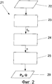
на Фиг.3 показана схематическая иллюстрация операций способа из первого способа определения рабочей точки,figure 3 shows a schematic illustration of the operations of the method of the first method of determining the operating point,
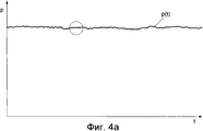
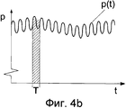
на Фиг.4а показан профиль давления в выпускном отверстии центробежного насоса,on figa shows the pressure profile in the outlet of the centrifugal pump,
на Фиг.4b показан профиль давления в подробностях,4b shows a pressure profile in detail,
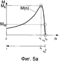
на фиг.5а показана характеристическая кривая "частота вращения/крутящий момент" асинхронного электродвигателя,on figa shows the characteristic curve "speed / torque" of an induction motor,
на Фиг.5b показана упрощенная характеристическая кривая "частота вращения/крутящий момент" асинхронного электродвигателя в его рабочем диапазоне,on fig.5b shows a simplified characteristic curve "speed / torque" of an induction motor in its operating range,
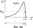
на фиг.6а и Фиг.6b показаны полученные из нее характеристические кривые n-Р асинхронного электродвигателя,on figa and fig.6b shows the characteristic curves obtained from it n-P induction motor,
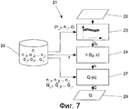
на чертеже Фиг.7 показана схематическая иллюстрация альтернативного способа, в котором используют зависящую от нагрузки характеристическую кривую "частота вращения/интенсивность нагнетания",FIG. 7 is a schematic illustration of an alternative method in which a load-dependent characteristic curve “speed / discharge rate” is used,
на Фиг.8 показана зависящая от нагрузки характеристическая кривая "частота вращения/интенсивность нагнетания",Fig. 8 shows a load-dependent characteristic curve "speed / discharge rate",
на Фиг.9 показана схематическая иллюстрация комбинированного способа определения рабочей точки,figure 9 shows a schematic illustration of a combined method for determining the operating point,
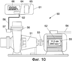
на Фиг.10 показана установка, представляющая собой центробежный насос, с устройством согласно настоящему изобретению для определения рабочей точки по измеренной пульсации давления,figure 10 shows the installation, which is a centrifugal pump, with a device according to the present invention for determining the operating point from the measured pressure pulsation,
на Фиг.11 показана установка, представляющая собой центробежный насос, с устройством согласно настоящему изобретению в виде мобильного телефона для определения рабочей точки, иfigure 11 shows the installation, which is a centrifugal pump, with the device according to the present invention in the form of a mobile phone for determining the operating point, and
на Фиг.12 показана еще одна установка с устройством, использующим мобильный телефон и сеть связи для определения рабочей точки в ином месте, чем место, где работает центробежный насос.on Fig shows another installation with a device using a mobile phone and a communication network to determine the operating point in a different place than the place where the centrifugal pump.
На Фиг.1а показана характеристическая кривая 2 "интенсивность нагнетания/высота подачи" центробежного насоса, известная как характеристическая кривая Q-H. Согласно предшествующему уровню техники высота Н подачи насоса может быть определена по разности давлений, измеренной между нагнетательной стороной и стороной всасывания центробежного насоса, и рабочая точка центробежного насоса может быть определена посредством характеристической кривой 2 "интенсивность нагнетания/высота подачи". Однако определение рабочей точки таким способом является недостаточно в диапазоне меньших интенсивностей нагнетания, в котором характеристическая кривая 2 "интенсивность нагнетания/высота подачи" является неоднозначной или неустойчивой. Такая характеристическая кривая, которая является неустойчивой, имеет эффект, заключающийся в том, что в случае конкретных измеренных разностей давлений для конкретной высоты Н подачи имеется два значения 3, 4 интенсивности нагнетания. Следовательно, нельзя вынести однозначное суждение о коэффициенте Q(H) подачи центробежного насоса.FIG. 1 a shows a
На фиг.1b показана характеристическая кривая 10 "интенсивность нагнетания/мощность" центробежного насоса, известная как характеристическая кривая Q-P. Показанная здесь характеристическая кривая 10 "интенсивность нагнетания/мощность" является однозначно определенной, так что при наличии информации о мощности, подводимой к насосу, можно иметь сведения о коэффициенте Q(P) подачи насоса и, следовательно, о его рабочей точки. Измерение электрической мощности, подводимой к установке, представляющей собой центробежный насос в сборе, на практике влечет за собой определенный объем затрат, поскольку оно производится в распределительном шкафу и требует затрат с точки зрения монтажа, который должен выполняться электриками с особой квалификацией. Обе характеристические кривые: характеристическая кривая 2 Q-H и характеристическая кривая 10 Q-P обычно являются документированными для конкретного центробежного насоса.Fig. 1b shows a characteristic curve "pumping intensity / power" of a centrifugal pump, known as a characteristic curve Q-P. The characteristic curve "pumping intensity / power" shown here is uniquely determined, so that if you have information about the power supplied to the pump, you can have information about the pumping coefficient Q (P) and, therefore, its operating point. Measurement of the electric power supplied to the unit, which is a complete centrifugal pump, in practice entails a certain amount of costs, since it is made in a control cabinet and requires costs in terms of installation, which must be performed by electricians with special qualifications. Both characteristic curves:
На Фиг.2 показана общая схематическая иллюстрация способа 21 согласно настоящему изобретению, в котором рабочую точку рабочей машины и/или асинхронного электродвигателя, приводящего ее в действие, определяют без использования переменных приводного асинхронного электродвигателя, получаемых путем электрических измерений. После регистрации 22 переменной, получаемой путем механических измерений, выполняют операцию 23, при которой определяют частоту, линейно пропорциональную звуку от вращения рабочей машины, а именно частоту fD звука от вращения, по измеренной переменной посредством анализа сигнала, в частности, частотного анализа. При следующей операции 24 по ней определяют частоту n вращения механизма привода. А при дальнейшей операции 25 определяют рабочую точку, характеризующуюся мощностью, подводимой к рабочей машине, которая обозначена здесь как P2, и/или ее коэффициентом Q подачи. Для этого, согласно настоящему изобретению, используют вызванную пробуксовкой зависимость "частота вращения/крутящий момент" асинхронного электродвигателя, приводящего в действие рабочую машину. Рабочая точка, определенная таким способом, является доступной при операции 29 для дополнительной обработки и/или индикации.Figure 2 shows a general schematic illustration of a
На Фиг.3 показана более подробная по сравнению с Фиг.2 схематическая иллюстрация операций способа из способа 21 определения рабочей точки. Показан способ 21 определения интенсивности нагнетания или коэффициента Q подачи, исходя из измеренной пульсации давления или измеренного шума, распространяющегося в твердом теле, или шума, распространяющегося по воздуху, посредством сохраненной модели электродвигателя и характеристической кривой насоса. Параметры, необходимые для выполнения отдельных операций способа, могут быть сохранены или занесены в файлы в хранилище 30 данных и являются доступными для выполнения отдельных операций способа. Необходимые параметры электродвигателя, а именно расчетная или номинальная выходная мощность P2N и номинальная частота nN вращения, и необязательные параметры электродвигателя, а именно частота f электрической сети, количество пар полюсов р или частота n0 синхронного вращения, формируют в этом случае модель электродвигателя, которую целесообразно хранить в первой части 31 хранилища 30 данных. Частота n0 синхронного вращения также может быть определена, исходя из частоты f электрической сети и количества пар полюсов p, или может быть получена из номинальной частоты nN вращения как теоретически возможная частота синхронного вращения, являющаяся следующей по порядку в сторону увеличения (например, 3600 мин-1, 3000 мин-1, 1800 мин-1, 1500 мин-1, 1200 мин-1, 1000 мин-1, 900 мин-1, 750 мин-1, 600 мин-1 или 500 мин-1). Если известен предельный перегрузочный момент Mk электродвигателя, то он может быть сохранен, но не является обязательным условием. Кроме того, может быть сохранена минимальная частота nmin вращения и максимальная частота nmax вращения. Характеристическую кривую "интенсивность нагнетания/мощность", то есть характеристическую кривую Q-P, центробежного насоса хранят во второй части 32 хранилища 30 данных. Эта характеристическая кривая задана множеством (i) опорных значений (![]()
![]()
![]()
![]()
![]()
![]()
![]()
![]()
При следующей операции 25 способа определяют выходную мощность P2 электродвигателя, исходя из определенной таким способом частоты n вращения привода. В этом случае применяют следующее уравнение:At the following
![]()
![]()
в которомwherein
Выходная мощность Р2 электродвигателя соответствует выходной мощности на валу насоса. Таким образом, при следующей операции 26 способа может быть определен коэффициент Q подачи насоса при помощи его характеристической кривой Q-P. Посредством этого способа рабочую точку рабочей машины, которой здесь является центробежный насос, определяют, исходя из измеряемой переменной и пульсации ее сигнала без измерения переменных, получаемых путем электрических измерений.The output power P 2 of the electric motor corresponds to the output power on the pump shaft. Thus, in the
На Фиг.4а проиллюстрирован профиль сигнала давления p(t), измеренного в выпускном отверстии центробежного насоса, в зависимости от времени t во время работы центробежного насоса. Можно заметить, что давление движется приблизительно на постоянном уровне, который остается одним и тем же.FIG. 4 a illustrates the profile of the pressure signal p (t) measured at the outlet of a centrifugal pump, as a function of time t during operation of the centrifugal pump. You may notice that the pressure moves at approximately a constant level, which remains the same.
На Фиг.4b этот профиль давления p(t) показан подробно. Можно заметить, что в профиле сигнала p(t) присутствуют пульсации давления. Было установлено, что согласно настоящему изобретению эти пульсации давления могут быть зарегистрированы серийно выпускаемыми датчиками давления для измерения статического давления. Во всяком случае, такие датчики давления установлены на многих насосах, в частности, для регистрации предельного давления в них. Такой датчик давления регистрирует пульсирующую составляющую сигнала давления. Частоту пульсирующей составляющей давления, то есть частоту fD звука от вращения получают из величины, обратной длительности Т периода. В способе согласно настоящему изобретению частоту пульсирующей составляющей давления определяют в соответствующем частотном диапазоне. Если количество z лопастей является известным, то пределы соответствующего частотного диапазона заданы нижней частотой ![]()
![]()
![]()
![]()
![]()
![]()
![]()
![]()
Здесь nmin - минимальная частота вращения, а nmax - максимальная частота вращения асинхронного электродвигателя, приводящего в действие центробежный насос. Они либо являются известными, либо могут быть вычислены в упрощенном виде, например, следующим образом:Here n min is the minimum rotational speed, and n max is the maximum rotational speed of an asynchronous electric motor, which drives a centrifugal pump. They are either known or can be calculated in a simplified form, for example, as follows:
![]()
![]()
иand
![]()
![]()
где n0 представляет собой частоту синхронного вращения. Для точного определения частоты звука от вращения в соответствующем частотном диапазоне в способе согласно настоящему изобретению точное определение частоты звука от вращения предпочтительно выполняют с точностью до одной десятой герца или даже до нескольких сотых долей герца. Этого достигают посредством очень высокой частоты дискретизации и/или посредством интервала дискретизации соответствующей длины. Частоту fD звука от вращения определяют посредством анализа сигнала, в частности частотного анализа, например, путем анализа методом быстрого преобразования Фурье (FFT) или автокорреляции. Как уже изложено, частота n вращения привода центробежного насоса или приводного электродвигателя, приводящего его в действие, может быть определена, исходя из частоты fD звука от вращения.where n 0 represents the frequency of synchronous rotation. To accurately determine the frequency of sound from rotation in the corresponding frequency range in the method according to the present invention, the exact determination of the frequency of sound from rotation is preferably performed with an accuracy of up to one tenth of hertz or even up to several hundredths of a hertz. This is achieved through a very high sampling rate and / or through a sampling interval of an appropriate length. The frequency f D of the sound from rotation is determined by signal analysis, in particular frequency analysis, for example, by analysis using the Fast Fourier Transform (FFT) method or autocorrelation. As already stated, the rotation frequency n of the drive of the centrifugal pump or the drive motor that drives it, can be determined based on the frequency f D of sound from rotation.
Фиг.5а и Фиг.5b служат для объяснения операции 25 способа. На чертеже Фиг.5а показана характеристическая кривая М(n) "частота вращения/крутящий момент", также именуемая ниже характеристической кривой n-M, асинхронного электродвигателя. Такая характеристическая кривая M(n) "частота вращения/крутящий момент" представляет собой график зависимости крутящего момента М от частоты п вращения асинхронного электродвигателя. Эта характеристическая кривая, которая, по существу, является известной и типичной для асинхронного электродвигателя, показывает расчетную или номинальную рабочую точку асинхронного электродвигателя в точке (МN; nN) в случае номинального крутящего момента MN и номинальной частоты nN вращения, которые здесь обведены кружками. На частоте по синхронного вращения крутящий момент асинхронного электродвигателя равен 0. Формула для крутящего момента M(n) получена в следующем виде:5a and 5b serve to explain the

На Фиг.6а показана полученная из нее характеристическая кривая "частота вращения/мощность" или, иными словами, характеристическая кривая n-P асинхронного электродвигателя, гдеFig. 6a shows the "speed / power" characteristic curve obtained from it, or, in other words, the n-P characteristic curve of an induction motor, where

В этом случае параметры электродвигателя, необходимые для вычисления характеристической кривой M(n) или P2(n), могут быть получены из данных из таблички с паспортными техническими данными асинхронного электродвигателя. В этом случае особенно целесообразно, если профиль характеристической кривой n-P определяют исключительно по данным из таблички с паспортными техническими данными, а именно по расчетной мощности P2N и по расчетной частоте nN вращения. Из этих двух параметров, которые обычно приведены на табличке с паспортными техническими данными каждого асинхронного электродвигателя, может быть получена частота посинхронного вращения. Предельный перегрузочный момент обычно является известным из спецификаций изготовителя или может быть грубо установлен кратным номинальному крутящему моменту с подходящей кратностью, например, равному утроенному номинальному крутящему моменту. Предельная перегрузочная частота nk вращения может быть вычислена согласно формуле (5).In this case, the motor parameters necessary for calculating the characteristic curve M (n) or P 2 (n) can be obtained from the data from the nameplate with the technical data sheet of the induction motor. In this case, it is especially advisable if the profile of the characteristic curve nP is determined solely from the data from the nameplate with the technical data, namely, the rated power P 2N and the calculated rotational speed n N. From these two parameters, which are usually shown on the nameplate with the technical data sheet of each induction motor, the frequency of synchronous rotation can be obtained. The overload limit is usually known from the manufacturer's specifications or can be roughly set to a multiple of the rated torque with a suitable ratio, for example, equal to three times the rated torque. The maximum overload rotation frequency n k can be calculated according to the formula (5).
В рабочем диапазоне рабочей машины характеристическая кривая "частота вращения/крутящий момент" асинхронного электродвигателя из Фиг.5а может быть аппроксимирована прямой линией, проходящей через точку (Mn; nN), заданную номинальным крутящим моментом MN на номинальной частоте nN вращения, и через точку (М=0; n0), заданную крутящим моментом М согласно 0 на частоте посинхронного вращения. Получена следующая упрощенная характеристическая кривая "частота вращения/крутящий момент", то есть характеристическая кривая n-M, асинхронного электродвигателя:In the operating range of the working machine, the characteristic curve "speed / torque" of the induction motor from Fig. 5a can be approximated by a straight line passing through the point (M n ; n N ) specified by the rated torque M N at the rated speed n N of rotation, and through the point (M = 0; n 0 ) specified by the torque M according to 0 at the synchronous rotation frequency. The following simplified characteristic curve "speed / torque" is obtained, that is, the characteristic curve nM, of an induction motor:
Эта аппроксимированная или упрощенная характеристическая кривая "частота вращения/крутящий момент" проиллюстрирована на Фиг.5b, а полученная из нее упрошенная характеристическая кривая "частота вращения/мощность" проиллюстрирована на Фиг.6b:This approximated or simplified rotational speed / torque characteristic curve is illustrated in Fig. 5b, and the simplified rotational speed / power characteristic curve obtained from it is illustrated in Fig. 6b:

В обоих случаях при операции 25 способа мощность P2(n), подводимая к рабочей машине, может быть определена по частоте n вращения привода с использованием упрощенной линейной характеристической кривой n-P согласно формуле (15) или характеристической кривой n-P согласно формуле (13), полученной из формулы Клосса (Kloss).In both cases, in
При операции 26 способа может быть определен коэффициент Q подачи при наличии сведений о мощности P2, подводимой к рабочей машине, и с использованием характеристической кривой Q-P.In
На Фиг.7 показана схематическая иллюстрация альтернативного способа 21 согласно настоящему изобретению, в котором используют зависящую от нагрузки характеристическую кривую "частота вращения/интенсивность нагнетания", или, иными словами, характеристическую кривую n-Q. В этом способе сведения о количестве z лопастей и зависящую от нагрузки характеристическую кривую n(Q) "частота вращения/интенсивность нагнетания", заданную множеством (i) опорных значений (![]()
![]()
![]()
![]()
![]()
![]()
![]()
![]()
![]()
![]()
![]()
![]()
На Фиг.9 показан комбинированный способ определения Q, в котором определение рабочей точки выполняют как по высоте Н подачи, так и по мощности P2. В этом способе также используют пульсацию давления p2 на нагнетательной стороне для определения выходной мощности P2 на валу и коэффициент Q подачи. Этот способ и в этот раз содержит операции 23, 24 и 25 способа, описанные на Фиг.3. И вновь параметры, уже описанные на Фиг.3, а также характеристическую кривую Q-P сохраняют в хранилище 30 данных. Кроме того, в нем хранят характеристическую кривую "интенсивность нагнетания/высота подачи", то есть характеристическую кривую Q-H, центробежного насоса. Для этого опорная таблица для характеристической кривой Q-P дополнена соответствующими значениями ![]()
![]()
![]()
![]()
![]()
![]()
Для определения коэффициента Q подачи выполняют операцию 28 способа, при которой определяют коэффициент подачи согласно комбинированному способу по характеристической кривой "интенсивность нагнетания/высота подачи" и по характеристической кривой "интенсивность нагнетания/мощность" центробежного насоса. Следовательно, определение рабочей точки может быть выполнено более точно и более надежно. При операции 15 способа вычисляют необходимую высоту Н подачи по предельному давлению р2 и давлению p1 всасывания.To determine the feed Q coefficient, a method step 28 is performed in which the feed coefficient is determined according to the combined method from the characteristic curve "discharge intensity / feed height" and the characteristic curve "discharge intensity / power" of the centrifugal pump. Therefore, the determination of the operating point can be performed more accurately and more reliably. In step 15 of the method, the required supply height H is calculated from the limit pressure p 2 and the suction pressure p 1 .
На Фиг.10 показана установка 50, представляющая собой центробежный насос, в которой центробежный насос 51 подсоединен через вал 53 к асинхронному электродвигателю 52, который приводит в действие центробежный насос 51. Для этого на асинхронный электродвигатель 52 подают электропитание из линии 54 электропитания. Асинхронный электродвигатель 52 имеет табличку 55 с паспортными техническими данными, содержащую количественные величины, характеризующие асинхронный электродвигатель 52. Подсоединенный напорный патрубок 56 центробежного насоса 51 имеет расположенный на нем датчик 57 давления для измерения давления на нагнетательной стороне или предельного давления центробежного насоса 51. Датчик 57 давления соединен через линию 58 с устройством 61 согласно настоящему изобретению. Устройство 61 согласно настоящему изобретению производит оценку измерительных сигналов из датчика 57 давления и определяет рабочую точку рабочей машины 51. Для этого в нем используют способ согласно настоящему изобретению. Данные из таблички с паспортными техническими данными, а именно номинальная мощность P2N и номинальная частота nN вращения, являются достаточными в качестве величин, характеризующих асинхронный электродвигатель, для выполнения этого способа. Исходя из них, могут быть получены или вычислены все остальные параметры электродвигателя. Устройство 61 имеет соединение или устройство 62 ввода сигнала, пригодное для регистрации сигналов давления. Была доказана целесообразность проектирования устройства 62 ввода сигнала для составляющих сигнала с частотой до 500 Гц. Такое устройство ввода является более рентабельным, чем устройство ввода с высокими динамическими характеристиками, которое может регистрировать сигналы в частотном диапазоне порядка нескольких килогерц и обеспечивает возможность регистрации с достаточным быстродействием и с достаточной чувствительностью. Кроме того, устройство 61 имеет блок 64 обработки сигналов, который определяет частоту fD звука от вращения с достаточной точностью. Блок 64 обработки сигналов способен определять частоту звука от вращения с точностью до одной десятой герца или до нескольких сотых долей герца. Он имеет высокую частоту дискретизации и/или интервалы дискретизации соответствующей длины. Вычислительный блок 65 обеспечивает управление способом, выполняемым в устройстве 61, и координирует его выполнение. Кроме того, устройство 61 имеет индикатор и/или операционный блок 66. Кроме того, на этом устройстве может быть предусмотрено еще одно соединение для датчика давления, которое не здесь проиллюстрировано и которое служит, например, для регистрации давления всасывания в насосе. Кроме того, это устройство может иметь дополнительные входы для сигналов, которые здесь не проиллюстрированы, и/или интерфейс последовательной шины, например, для ввода или вывода считанных параметров.Figure 10 shows the
На Фиг.11 показана установка, представляющая собой центробежный насос, которая состоит из центробежного насоса 51 и асинхронного электродвигателя 52, и устройство для определения рабочей точки в виде мобильного телефона 71. Оно определяет рабочую точку центробежного насоса 51 по шуму, распространяющемуся по воздуху, который передается центробежным насосом 51. Для этого мобильный телефон 71 имеет встроенный микрофон 72. В этом варианте осуществления изобретения, который приведен в качестве примера, в мобильном телефоне 71 используют способ согласно настоящему изобретению. Для этого в хранилище данных мобильного телефона 71, которое здесь не проиллюстрировано, может храниться надлежащая запрограммированная последовательность, и она может обрабатываться находящимся в мобильном телефоне вычислительным блоком, который здесь не проиллюстрирован.Figure 11 shows the installation, which is a centrifugal pump, which consists of a
Как проиллюстрировано на Фиг.12, устройство может также определять рабочую точку рабочей машины, будучи пространственно отделенным от нее. На Фиг.12 показана та же самая установка, представляющая собой центробежный насос, что и на Фиг. 11, которая состоит из центробежного насоса 51 и асинхронного электродвигателя 52. Мобильный телефон 71 со встроенным микрофоном 72 регистрирует рабочие шумы рабочей машины 51 в месте 78 работы центробежного насоса 51 и асинхронного электродвигателя 52, которое обозначено пунктирной линией. Для этого мобильный телефон 71 регистрирует сигналы шума, распространяющегося по воздуху, от рабочей машины 51. Устройство 61 для определения рабочей точки, будучи пространственно отделенным от рабочей машины 51, расположено в месте 79, где выполняют определение рабочей точки. В устройстве 61 используют средство связи, которое служит средством передачи сигнала для выполнения определения рабочей точки, будучи пространственно отделенным от рабочей машины 51. Сигналы шума, распространяющегося по воздуху, от центробежного насоса 51, которые зарегистрированы мобильным телефоном 71, передают или переправляют в устройство 61 посредством сети 77 связи.As illustrated in FIG. 12, the device can also determine the operating point of the working machine, being spatially separated from it. FIG. 12 shows the same installation as a centrifugal pump as in FIG. 11, which consists of a
Claims (20)
- операции определения характеристической кривой (М(n)) "частота вращения/крутящий момент" электродвигателя (52), в частности, посредством заданных параметров электродвигателя, а именно расчетной мощности (P2N) и расчетной частоты (nN) вращения, а при необходимости, частоты (n0) синхронного вращения, предельного перегрузочного момента (Mk), предельной перегрузочной частоты (nk) вращения или предельной перегрузочной пробуксовки (sk);
- операции определения подводимой мощности (p2) или крутящего момента (М) электродвигателя (52), исходя из определенной частоты (n) вращения привода и характеристической кривой (М(n)) "частота вращения/крутящий момент" электродвигателя (52).2. The method according to claim 1, characterized in that the power supplied to the working machine (P 2 ) is determined by the following operations:
- the operation of determining the characteristic curve (M (n)) "speed / torque" of the electric motor (52), in particular, by the specified parameters of the electric motor, namely, the rated power (P 2N ) and the calculated frequency (n N ) of rotation, and when if necessary, the frequency (n 0 ) of synchronous rotation, the maximum overload torque (M k ), the maximum overload frequency (n k ) rotation or the maximum overload slip (s k );
- the operation of determining the input power (p 2 ) or torque (M) of the electric motor (52), based on a certain frequency (n) of rotation of the drive and the characteristic curve (M (n)) "speed / torque" of the electric motor (52).
- операции определения характеристической кривой (М(n)) "частота вращения/крутящий момент" электродвигателя (52), в частности, посредством заданных параметров электродвигателя, а именно расчетной мощности (P2N) и расчетной частоты (nN) вращения, а при необходимости, частоты (n0) синхронного вращения, предельного перегрузочного момента (Mk), предельной перегрузочной частоты (nk) вращения или предельной перегрузочной пробуксовки (sk);
- операции определения подводимой мощности (@Р2) или крутящего момента (М) электродвигателя (52) по частоте (n) вращения привода и характеристической кривой (М(n)) "частота вращения/крутящий момент" электродвигателя (52).11. The device according to claim 10, characterized in that the power supplied to the working machine is determined by the following operations:
- the operation of determining the characteristic curve (M (n)) "speed / torque" of the electric motor (52), in particular, by the specified parameters of the electric motor, namely, the rated power (P 2N ) and the calculated frequency (n N ) of rotation, and when if necessary, the frequency (n 0 ) of synchronous rotation, the maximum overload torque (M k ), the maximum overload frequency (n k ) rotation or the maximum overload slip (s k );
- the operation of determining the input power (@ P2) or torque (M) of the electric motor (52) from the frequency (n) of the drive rotation and the characteristic curve (M (n)) "speed / torque" of the electric motor (52).
Applications Claiming Priority (3)
| Application Number | Priority Date | Filing Date | Title |
|---|---|---|---|
| DE102009022107A DE102009022107A1 (en) | 2009-05-20 | 2009-05-20 | Method and device for determining the operating point of a work machine |
| DE102009022107.7 | 2009-05-20 | ||
| PCT/EP2010/055621 WO2010133425A1 (en) | 2009-05-20 | 2010-04-27 | Method and device for determining an operating point of a work machine |
Publications (2)
| Publication Number | Publication Date |
|---|---|
| RU2011151763A RU2011151763A (en) | 2013-07-10 |
| RU2536656C2 true RU2536656C2 (en) | 2014-12-27 |
Family
ID=42286674
Family Applications (1)
| Application Number | Title | Priority Date | Filing Date |
|---|---|---|---|
| RU2011151763/06A RU2536656C2 (en) | 2009-05-20 | 2010-04-27 | Method and device for determination of working machine working point |
Country Status (15)
| Country | Link |
|---|---|
| US (1) | US8763464B2 (en) |
| EP (1) | EP2433010B1 (en) |
| JP (1) | JP5868846B2 (en) |
| CN (1) | CN102439318B (en) |
| BR (1) | BRPI1007672B1 (en) |
| DE (1) | DE102009022107A1 (en) |
| DK (1) | DK2433010T3 (en) |
| ES (1) | ES2556236T3 (en) |
| HR (1) | HRP20151394T1 (en) |
| HU (1) | HUE028262T2 (en) |
| PL (1) | PL2433010T3 (en) |
| PT (1) | PT2433010E (en) |
| RU (1) | RU2536656C2 (en) |
| SI (1) | SI2433010T1 (en) |
| WO (1) | WO2010133425A1 (en) |
Cited By (1)
| Publication number | Priority date | Publication date | Assignee | Title |
|---|---|---|---|---|
| RU2776905C2 (en) * | 2018-01-16 | 2022-07-28 | Ксб Се & Ко. Кгаа | Method for self-diagnostics of mechanical and/or hydraulic state of centrifugal pump |
Families Citing this family (31)
| Publication number | Priority date | Publication date | Assignee | Title |
|---|---|---|---|---|
| DE102011101599B4 (en) * | 2011-05-13 | 2021-08-05 | Sew-Eurodrive Gmbh & Co Kg | System for the determination of structure-borne noise in a test object |
| ITCO20110069A1 (en) * | 2011-12-20 | 2013-06-21 | Nuovo Pignone Spa | TEST ARRANGEMENT FOR A STAGE OF A CENTRIFUGAL COMPRESSOR |
| EP2618002B1 (en) * | 2012-01-17 | 2016-05-04 | ABB Technology Oy | Method for detecting the correct rotational direction of a centrifugal apparatus, and a centrifugal apparatus assembly |
| KR20130115488A (en) | 2012-04-12 | 2013-10-22 | 엘에스산전 주식회사 | Apparatus for alarming inverter status and apparatus for analyzing motor status in mobile terminal |
| DE102012013774A1 (en) * | 2012-07-11 | 2014-01-16 | Wilo Se | Centrifugal pump with flow meter |
| DE102013017828B4 (en) | 2013-10-24 | 2015-05-13 | Fresenius Medical Care Deutschland Gmbh | Method and device for monitoring an in an extracorporeal blood circulation or arranged in a Dialysatkreislauf impeller pump and blood treatment device |
| DE102014214033A1 (en) * | 2014-07-18 | 2016-01-21 | Ksb Aktiengesellschaft | Determining the flow rate of a pump |
| US10316849B2 (en) | 2014-10-15 | 2019-06-11 | Grundfos Holding A/S | Method and system for detection of faults in pump assembly via handheld communication device |
| US9785126B2 (en) * | 2014-11-25 | 2017-10-10 | Rockwell Automation Technologies, Inc. | Inferred energy usage and multiple levels of energy usage |
| DE102015215466A1 (en) | 2015-08-13 | 2017-02-16 | Ksb Aktiengesellschaft | Adjustment of the flow rate of a consumer |
| CN108071626B (en) * | 2016-11-17 | 2021-03-26 | 恩格尔机械(上海)有限公司 | Molding machine and method for operating the same |
| EP3242036B1 (en) * | 2016-12-30 | 2020-10-28 | Grundfos Holding A/S | Method for detecting a condition of a pump unit |
| EP3242033B1 (en) * | 2016-12-30 | 2024-05-01 | Grundfos Holding A/S | Method for operating an electronically controlled pump unit |
| US10697318B2 (en) * | 2017-01-12 | 2020-06-30 | General Electric Company | Efficiency maps for tracking component degradation |
| DE102017111479A1 (en) * | 2017-05-24 | 2018-11-29 | Hengst Se | Method for operating a centrifugal separator |
| DE102017213131A1 (en) | 2017-07-31 | 2019-01-31 | Robert Bosch Gmbh | Method and control device for controlling an actuator of a system and such a system |
| DE102017214203A1 (en) | 2017-08-15 | 2019-02-21 | KSB SE & Co. KGaA | Cyber attack cavitation protection method and apparatus for performing the method |
| CN111316177B (en) | 2017-11-15 | 2024-06-25 | Ksb股份有限公司 | Method and apparatus for protecting a pump assembly from network attacks |
| DE102018200651A1 (en) * | 2018-01-16 | 2019-07-18 | KSB SE & Co. KGaA | Method for the self-diagnosis of the mechanical and / or hydraulic condition of a centrifugal pump |
| WO2019147750A2 (en) * | 2018-01-24 | 2019-08-01 | Magnetic Pumping Solutions, Llc | Method and system for monitoring the condition of rotating systems |
| DE102018104394A1 (en) * | 2018-02-27 | 2019-08-29 | Ebm-Papst Mulfingen Gmbh & Co. Kg | Operating point determination |
| DE102018211869A1 (en) * | 2018-07-17 | 2020-01-23 | Ziehl-Abegg Se | Method for determining a fluid delivery parameter |
| EP3618266A1 (en) * | 2018-08-28 | 2020-03-04 | Siemens Aktiengesellschaft | Determining the rotational speed of a rotor on by vibration analysis |
| AT522652A1 (en) * | 2019-05-23 | 2020-12-15 | Plasser & Theurer Export Von Bahnbaumaschinen Gmbh | Method and device for controlling / regulating a rotary drive of a working unit of a track construction machine |
| IT201900009747A1 (en) * | 2019-06-21 | 2020-12-21 | Calpeda A Spa | Method of management and control of a pressurization system |
| GB2591100A (en) * | 2020-01-14 | 2021-07-21 | Edwards Ltd | Vacuum pump monitoring method and apparatus |
| DE102020005050A1 (en) * | 2020-08-18 | 2022-02-24 | KSB SE & Co. KGaA | Method for determining a synchronous speed |
| EP4361582A1 (en) | 2022-10-24 | 2024-05-01 | Wilo Se | Method for examining the state of a pump unit and software application, storage medium and examination device for carrying out said method |
| DE102022128744A1 (en) | 2022-10-28 | 2024-05-08 | KSB SE & Co. KGaA | Method for exchanging information between an external receiver and a pump |
| EP4386210A1 (en) * | 2022-12-14 | 2024-06-19 | Schneider Toshiba Inverter Europe SAS | Method for identification of impeller wear and excessive wear-ring clearance in centrifugal pumps |
| CN116292336B (en) * | 2023-05-12 | 2023-09-19 | 安徽明泉水设备有限公司 | Water pump blade detection method |
Citations (4)
| Publication number | Priority date | Publication date | Assignee | Title |
|---|---|---|---|---|
| DE2946049A1 (en) * | 1979-11-15 | 1981-05-27 | Hoechst Ag, 6000 Frankfurt | Circulation pump flow-rate regulation system - measures pump loading and rotation to obtain actual flow-rate |
| SU1665087A1 (en) * | 1989-04-29 | 1991-07-23 | Ульяновское высшее военно-техническое училище им.Богдана Хмельницкого | Pump unit |
| DE19618462A1 (en) * | 1996-05-08 | 1997-11-13 | Status Pro Maschinenmesstechni | Extrinsic power parameter determination method for energy conversion appliance |
| RU2256100C1 (en) * | 2004-08-18 | 2005-07-10 | Гаспарянц Рубен Саргисович | Method of diagnosing condition of electric motor of main line pumps of oil transfer station of main oil line operating at overloading |
Family Cites Families (22)
| Publication number | Priority date | Publication date | Assignee | Title |
|---|---|---|---|---|
| JPS63198792A (en) * | 1987-02-13 | 1988-08-17 | Toshiba Corp | Pump controller |
| DD258467A1 (en) | 1987-03-12 | 1988-07-20 | Nahrungsguetermaschinenbau Veb | ARRANGEMENT FOR DETERMINING THE PERFORMANCE AND / OR THE MOMENT OF INDUCTION MOTORS |
| DE3927476A1 (en) * | 1989-08-19 | 1991-02-21 | Guenther & Co Gmbh & Co | Drive torque and power measurement of electric motor - comprising drive train mechanical rotation frequency with motor stator field rotation frequency |
| US5267453A (en) * | 1991-06-06 | 1993-12-07 | Guilford Mills, Inc. | Loop-type textile fastener fabric and method of producing same |
| DE4330097A1 (en) * | 1993-09-06 | 1995-03-09 | Klein Schanzlin & Becker Ag | Centrifugal pump housing with delivery rate measuring device |
| US6260004B1 (en) * | 1997-12-31 | 2001-07-10 | Innovation Management Group, Inc. | Method and apparatus for diagnosing a pump system |
| JP2000136790A (en) * | 1998-11-04 | 2000-05-16 | Hitachi Ltd | Gate pump device |
| DE19858946A1 (en) * | 1998-12-09 | 2000-06-15 | Ver Energiewerke Ag | Detecting cavitation in multiple stage centrifugal pump involves comparing pressure difference between input and one pump stage with desired delivery value for a pump stage |
| DE10039917A1 (en) * | 2000-08-16 | 2002-02-28 | Ksb Ag | Method and device for determining the delivery rate of a centrifugal pump |
| JP3723866B2 (en) * | 2001-02-07 | 2005-12-07 | 株式会社日立製作所 | Internal pump performance monitoring method and apparatus |
| US6536271B1 (en) * | 2001-09-13 | 2003-03-25 | Flowserve Management Company | Pump with integral flow monitoring |
| US6648606B2 (en) * | 2002-01-17 | 2003-11-18 | Itt Manufacturing Enterprises, Inc. | Centrifugal pump performance degradation detection |
| GB0217494D0 (en) * | 2002-07-29 | 2002-09-04 | Boc Group Plc | Conditioning monitoring of pumps and pump systems |
| DE10334817A1 (en) * | 2003-07-30 | 2005-03-10 | Bosch Rexroth Ag | Pump failure detection unit uses Fourier analysis of pressure sensor measurement to determine if characteristic frequency exceeds reference amplitude |
| DE10359726A1 (en) | 2003-12-19 | 2005-07-14 | Ksb Aktiengesellschaft | quantity measurement |
| EP1564411B2 (en) * | 2004-02-11 | 2015-08-05 | Grundfos A/S | Method for detecting operation errors of a pump aggregate |
| JP2006307682A (en) * | 2005-04-26 | 2006-11-09 | Ebara Densan Ltd | Pump device |
| DE102006049440B4 (en) | 2005-10-17 | 2014-08-21 | Ifm Electronic Gmbh | Method, sensor and diagnostic device for pump diagnosis |
| US7693684B2 (en) * | 2005-10-17 | 2010-04-06 | I F M Electronic Gmbh | Process, sensor and diagnosis device for pump diagnosis |
| JP4625777B2 (en) * | 2006-02-28 | 2011-02-02 | 株式会社東芝 | Pump soundness evaluation system, pump soundness evaluation device and its evaluation method, evaluation program |
| DE102007022348A1 (en) * | 2007-05-12 | 2008-11-13 | Ksb Aktiengesellschaft | Device and method for fault monitoring |
| JP4843105B2 (en) * | 2008-11-28 | 2011-12-21 | 住友重機械工業株式会社 | Control method for hybrid work machine and pump output limiting method for hybrid work machine |
-
2009
- 2009-05-20 DE DE102009022107A patent/DE102009022107A1/en not_active Withdrawn
-
2010
- 2010-04-27 CN CN201080022540.XA patent/CN102439318B/en active Active
- 2010-04-27 HU HUE10717116A patent/HUE028262T2/en unknown
- 2010-04-27 ES ES10717116.7T patent/ES2556236T3/en active Active
- 2010-04-27 RU RU2011151763/06A patent/RU2536656C2/en active
- 2010-04-27 EP EP10717116.7A patent/EP2433010B1/en active Active
- 2010-04-27 WO PCT/EP2010/055621 patent/WO2010133425A1/en active Application Filing
- 2010-04-27 SI SI201031081T patent/SI2433010T1/en unknown
- 2010-04-27 BR BRPI1007672-7A patent/BRPI1007672B1/en active IP Right Grant
- 2010-04-27 PL PL10717116T patent/PL2433010T3/en unknown
- 2010-04-27 DK DK10717116.7T patent/DK2433010T3/en active
- 2010-04-27 PT PT107171167T patent/PT2433010E/en unknown
- 2010-04-27 JP JP2012511220A patent/JP5868846B2/en active Active
-
2011
- 2011-11-18 US US13/300,261 patent/US8763464B2/en active Active
-
2015
- 2015-12-21 HR HRP20151394TT patent/HRP20151394T1/en unknown
Patent Citations (4)
| Publication number | Priority date | Publication date | Assignee | Title |
|---|---|---|---|---|
| DE2946049A1 (en) * | 1979-11-15 | 1981-05-27 | Hoechst Ag, 6000 Frankfurt | Circulation pump flow-rate regulation system - measures pump loading and rotation to obtain actual flow-rate |
| SU1665087A1 (en) * | 1989-04-29 | 1991-07-23 | Ульяновское высшее военно-техническое училище им.Богдана Хмельницкого | Pump unit |
| DE19618462A1 (en) * | 1996-05-08 | 1997-11-13 | Status Pro Maschinenmesstechni | Extrinsic power parameter determination method for energy conversion appliance |
| RU2256100C1 (en) * | 2004-08-18 | 2005-07-10 | Гаспарянц Рубен Саргисович | Method of diagnosing condition of electric motor of main line pumps of oil transfer station of main oil line operating at overloading |
Cited By (1)
| Publication number | Priority date | Publication date | Assignee | Title |
|---|---|---|---|---|
| RU2776905C2 (en) * | 2018-01-16 | 2022-07-28 | Ксб Се & Ко. Кгаа | Method for self-diagnostics of mechanical and/or hydraulic state of centrifugal pump |
Also Published As
| Publication number | Publication date |
|---|---|
| WO2010133425A1 (en) | 2010-11-25 |
| BRPI1007672A2 (en) | 2016-08-02 |
| ES2556236T3 (en) | 2016-01-14 |
| EP2433010A1 (en) | 2012-03-28 |
| DK2433010T3 (en) | 2015-12-21 |
| CN102439318B (en) | 2015-10-21 |
| US8763464B2 (en) | 2014-07-01 |
| CN102439318A (en) | 2012-05-02 |
| EP2433010B1 (en) | 2015-09-23 |
| PT2433010E (en) | 2016-01-26 |
| US20120111114A1 (en) | 2012-05-10 |
| JP5868846B2 (en) | 2016-02-24 |
| HUE028262T2 (en) | 2016-12-28 |
| HRP20151394T1 (en) | 2016-02-12 |
| RU2011151763A (en) | 2013-07-10 |
| PL2433010T3 (en) | 2016-03-31 |
| SI2433010T1 (en) | 2016-01-29 |
| JP2012527563A (en) | 2012-11-08 |
| DE102009022107A1 (en) | 2010-11-25 |
| BRPI1007672B1 (en) | 2020-10-27 |
Similar Documents
| Publication | Publication Date | Title |
|---|---|---|
| RU2536656C2 (en) | Method and device for determination of working machine working point | |
| US6648606B2 (en) | Centrifugal pump performance degradation detection | |
| US6564627B1 (en) | Determining centrifugal pump suction conditions using non-traditional method | |
| US6774601B2 (en) | System and method for predicting mechanical failures in machinery driven by an induction motor | |
| CN105372064B (en) | Construction machinery gear box assembly performance tests and analyzes test method | |
| CN102734183B (en) | For detecting method and the mechanism of the wearing and tearing of the pump being controlled by frequency variator | |
| Ahonen | Monitoring of centrifugal pump operation by a frequency converter | |
| US20130204546A1 (en) | On-line pump efficiency determining system and related method for determining pump efficiency | |
| WO2010092238A1 (en) | Energy efficiency observer | |
| US7693684B2 (en) | Process, sensor and diagnosis device for pump diagnosis | |
| JP2021530703A (en) | Methods and systems for evaluating the vibration behavior of electric motors | |
| CN103321916A (en) | Water pump working condition monitoring method and device based on DSP embedded system | |
| CN103868649A (en) | On-line dynamic balancing correction method for rotors of double-rotor axial flow fan | |
| CN102734184A (en) | Method and arrangement for estimating flow rate of pump | |
| CN112460040A (en) | Pump sound wave monitoring system and method | |
| CN103821733B (en) | The method and apparatus determining the hydrostatic head of fluid delivery system for approximation | |
| CN110259702A (en) | A kind of centrifugal pump operational effect determination method | |
| JP2021121788A (en) | Diagnostic device, diagnostic method, diagnostic program, and diagnostic system | |
| CN102734195B (en) | The stall in the blower fan of frequency variator is utilized to detect | |
| CN104632606A (en) | Pumping unit on-line energy consumption testing and analyzing system and method | |
| CN103671066A (en) | Acoustic-emission-technology-based device for detecting small-flow working condition unstable flow of centrifugal pump | |
| JPH06100198B2 (en) | Pump life prediction method | |
| He et al. | A Vibration Acceleration Sensor-based Shock Pulse Method for Condition Evaluation of Rolling Bearings | |
| RU2809309C1 (en) | Method for vibration diagnostics of technical condition of gas pumping unit | |
| US20240352939A1 (en) | Method for quantitatively determining current operating-state-dependent variables, more particularly the current conveyed volumetric flow rate, or a fan, and fan for application of the method |