RU2532142C2 - Method and system to monitor partial discharges - Google Patents
Method and system to monitor partial discharges Download PDFInfo
- Publication number
- RU2532142C2 RU2532142C2 RU2011108221/28A RU2011108221A RU2532142C2 RU 2532142 C2 RU2532142 C2 RU 2532142C2 RU 2011108221/28 A RU2011108221/28 A RU 2011108221/28A RU 2011108221 A RU2011108221 A RU 2011108221A RU 2532142 C2 RU2532142 C2 RU 2532142C2
- Authority
- RU
- Russia
- Prior art keywords
- pulse
- frequency components
- failure
- spectra
- pulses
- Prior art date
Links
Images


Classifications
-
- G—PHYSICS
- G01—MEASURING; TESTING
- G01R—MEASURING ELECTRIC VARIABLES; MEASURING MAGNETIC VARIABLES
- G01R31/00—Arrangements for testing electric properties; Arrangements for locating electric faults; Arrangements for electrical testing characterised by what is being tested not provided for elsewhere
- G01R31/12—Testing dielectric strength or breakdown voltage ; Testing or monitoring effectiveness or level of insulation, e.g. of a cable or of an apparatus, for example using partial discharge measurements; Electrostatic testing
- G01R31/1227—Testing dielectric strength or breakdown voltage ; Testing or monitoring effectiveness or level of insulation, e.g. of a cable or of an apparatus, for example using partial discharge measurements; Electrostatic testing of components, parts or materials
- G01R31/1263—Testing dielectric strength or breakdown voltage ; Testing or monitoring effectiveness or level of insulation, e.g. of a cable or of an apparatus, for example using partial discharge measurements; Electrostatic testing of components, parts or materials of solid or fluid materials, e.g. insulation films, bulk material; of semiconductors or LV electronic components or parts; of cable, line or wire insulation
- G01R31/1272—Testing dielectric strength or breakdown voltage ; Testing or monitoring effectiveness or level of insulation, e.g. of a cable or of an apparatus, for example using partial discharge measurements; Electrostatic testing of components, parts or materials of solid or fluid materials, e.g. insulation films, bulk material; of semiconductors or LV electronic components or parts; of cable, line or wire insulation of cable, line or wire insulation, e.g. using partial discharge measurements
-
- G—PHYSICS
- G01—MEASURING; TESTING
- G01R—MEASURING ELECTRIC VARIABLES; MEASURING MAGNETIC VARIABLES
- G01R1/00—Details of instruments or arrangements of the types included in groups G01R5/00 - G01R13/00 and G01R31/00
-
- H—ELECTRICITY
- H01—ELECTRIC ELEMENTS
- H01B—CABLES; CONDUCTORS; INSULATORS; SELECTION OF MATERIALS FOR THEIR CONDUCTIVE, INSULATING OR DIELECTRIC PROPERTIES
- H01B1/00—Conductors or conductive bodies characterised by the conductive materials; Selection of materials as conductors
-
- H—ELECTRICITY
- H01—ELECTRIC ELEMENTS
- H01L—SEMICONDUCTOR DEVICES NOT COVERED BY CLASS H10
- H01L21/00—Processes or apparatus adapted for the manufacture or treatment of semiconductor or solid state devices or of parts thereof
-
- H—ELECTRICITY
- H01—ELECTRIC ELEMENTS
- H01L—SEMICONDUCTOR DEVICES NOT COVERED BY CLASS H10
- H01L2221/00—Processes or apparatus adapted for the manufacture or treatment of semiconductor or solid state devices or of parts thereof covered by H01L21/00
-
- H—ELECTRICITY
- H02—GENERATION; CONVERSION OR DISTRIBUTION OF ELECTRIC POWER
- H02B—BOARDS, SUBSTATIONS OR SWITCHING ARRANGEMENTS FOR THE SUPPLY OR DISTRIBUTION OF ELECTRIC POWER
- H02B1/00—Frameworks, boards, panels, desks, casings; Details of substations or switching arrangements
Abstract
Description
Область техникиTechnical field
Настоящее изобретение относится к способу и системе мониторинга частичных разрядов, происходящих в электрической системе, и к способу измерения или анализа частичных разрядов происходящих в электрической системе.The present invention relates to a method and system for monitoring partial discharges occurring in an electrical system, and to a method for measuring or analyzing partial discharges occurring in an electrical system.
Уровень техникиState of the art
Изоляция высоковольтных, обычно трехфазных электрических или энергетических систем, часто испытывает воздействие происходящих в них импульсов. Эти импульсы обычно возникают вследствие разрядов на неоднородных границах внутри высоковольтных электрических или энергетических систем, таких как зазоры в изоляции кабелей и т.п. Следует учитывать, что часто эти разряды представляют собой частичные разряды внутри высоковольтных электрических или энергетических систем.Insulation of high-voltage, usually three-phase electrical or energy systems is often affected by the pulses occurring in them. These pulses usually occur due to discharges at inhomogeneous boundaries inside high-voltage electrical or energy systems, such as gaps in cable insulation, etc. It should be borne in mind that often these discharges are partial discharges inside high-voltage electrical or energy systems.
Таким образом, в основу настоящего изобретения положена задача создания по меньшей мере способа и системы мониторинга (отслеживания) или обнаружения частичных разрядов, происходящих в трехфазных электрических или энергетических системах.Thus, the present invention is based on the task of creating at least a method and system for monitoring (tracking) or detecting partial discharges occurring in three-phase electrical or energy systems.
Сущность изобретенияSUMMARY OF THE INVENTION
Согласно первой особенности изобретения предложен способ мониторинга частичных разрядов в электрической системе, в котором:According to a first aspect of the invention, there is provided a method for monitoring partial discharges in an electrical system, in which:
принимают от электрической системы сигнал или импульс или связанную с ним информацию,receive a signal or impulse or related information from the electrical system,
разбивают принятый сигнал или импульс на предварительно заданные частотные составляющие,break the received signal or pulse into predefined frequency components,
распознают шум или дублированные сигналы в принятом сигнале или импульсе иrecognize noise or duplicate signals in the received signal or pulse and
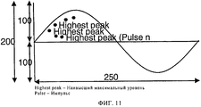
отображают максимальный уровень принятого сигнала или импульса на диаграмме разброса вместе с другими максимальными уровнями сходных предварительно заданных частотных составляющих.display the maximum level of the received signal or impulse on the scatterplot along with other maximum levels of similar predefined frequency components.
При осуществлении способа может генерироваться электронный блокнот для хранения заданного числа нормированных спектров различных сигналов или импульсов вместе со значениями максимальных уровней сигналов или импульсов.When implementing the method, an electronic notebook can be generated to store a given number of normalized spectra of various signals or pulses along with the values of the maximum levels of signals or pulses.
При осуществлении способа также:When implementing the method also:
сохраняют в базе данных множество спектров отказов,save a lot of failure spectra in the database,
отслеживают прием электрической системой сигналов или импульсов, возникающих в электрической системе, иmonitoring the reception by the electrical system of signals or pulses arising in the electrical system, and
после приема сигнала или импульса сравнивают частотный спектр обнаруженного сигнала или импульса с множеством спектров отказов, хранящихся в электронном блокноте или базе данных, чтобы по меньшей мере устанавливать наличие преимущественного соответствия частотного спектра обнаруженного сигнала или импульса любому из хранящегося множества спектров отказов.after receiving a signal or impulse, the frequency spectrum of the detected signal or impulse is compared with a plurality of failure spectra stored in an electronic notepad or database to at least establish that the frequency spectrum of the detected signal or impulse corresponds predominantly to any of the stored multiple failure spectra.
При осуществлении способа могут дополнительно группироваться спектры отказов, спектральный состав которых является сходным в предварительно заданных пределах.During the implementation of the method, failure spectra can be further grouped, the spectral composition of which is similar within predetermined limits.
При осуществлении способа также выставляют соответствующий флаг, если частотный спектр обнаруженного импульса преимущественно соответствует любому из существующих спектров отказов.When implementing the method, the corresponding flag is also set if the frequency spectrum of the detected pulse mainly corresponds to any of the existing failure spectra.
При выставлении флага может генерироваться дескриптор отказов. Вместо этого или дополнительно дескриптором отказов может являться флаг.When the flag is set, a fault descriptor may be generated. Instead, or additionally, a flag may be a failure descriptor.
При осуществлении способа в дополнение к выставлению флага в базе данных могут сохраняться данные или частотный спектр принятого сигнала или импульса, если частотный спектр обнаруженного импульса преимущественно не соответствует любому из существующих спектров отказов.When implementing the method, in addition to setting the flag, data or the frequency spectrum of the received signal or pulse can be stored in the database if the frequency spectrum of the detected pulse mainly does not correspond to any of the existing failure spectra.
При осуществлении способа могут генерироваться диаграммы разброса на основании подмножества спектров отказов принятого сигнала или импульса.When implementing the method, scatter patterns can be generated based on a subset of the failure spectra of the received signal or pulse.
При осуществлении способа может осуществляться обработка принятого сигнала или импульса.When implementing the method, the processing of the received signal or pulse can be carried out.
При осуществлении способа может дополнительно:When implementing the method may additionally:
генерироваться частотный спектр принятого сигнала или импульса иthe frequency spectrum of the received signal or pulse is generated and
осуществляться разбиение частотного спектра на предварительно заданные частотные составляющие.the frequency spectrum is divided into predefined frequency components.
Сравнение частотного спектра обнаруженного или принятого сигнала или импульса с существующими спектрами отказов, хранящимися в базе данных, может осуществляться посредством алгоритма сопоставления отказов.Comparison of the frequency spectrum of the detected or received signal or impulse with existing failure spectra stored in the database can be performed using the failure matching algorithm.
При осуществлении способа могут преимущественно:When implementing the method can mainly:
проверяться достоверность принятого сигнала или импульса,the validity of the received signal or impulse is checked,
определяться значение максимального уровня принятого сигнала или импульса иdetermine the value of the maximum level of the received signal or pulse and
нормироваться (нормализоваться) значения максимального уровня каждой из предварительно заданных частотных составляющих обнаруженного импульса к виду максимального уровня.normalize (normalize) the values of the maximum level of each of the predefined frequency components of the detected pulse to the form of the maximum level.
Согласно второй особенности изобретения предложена система мониторинга частичных разрядов в электрической системе, содержащая:According to a second aspect of the invention, there is provided a system for monitoring partial discharges in an electrical system, comprising:
базу данных для хранения множества спектров отказов,a database for storing multiple failure spectra,
контрольный модуль для отслеживания приема электрической системой сигналов или импульсов или связанной с ними информации иa control module for monitoring the reception by the electrical system of signals or pulses or related information, and
компаратор, способный после приема сигнала или импульса сравнивать частотный спектр принятого сигнала или импульса с существующими спектрами отказов, хранящимися в базе данных,a comparator capable of comparing, after receiving a signal or pulse, the frequency spectrum of the received signal or pulse with existing failure spectra stored in a database,
чтобы по меньшей мере устанавливать наличие преимущественного соответствия частотного спектра принятого сигнала или импульса любому из хранящихся спектров отказов.in order to at least establish the existence of a predominant correspondence of the frequency spectrum of the received signal or pulse to any of the stored failure spectra.
В системе может быть предусмотрено выставление флага, если частотный спектр принятого сигнала или импульса по существу соответствует любому из существующих спектров отказов.A flag may be provided in the system if the frequency spectrum of the received signal or pulse substantially matches any of the existing failure spectra.
В системе может быть предусмотрено сохранение данных или частотного спектра принятого сигнала или импульса в базе данных.The system may provide for the storage of data or the frequency spectrum of the received signal or pulse in a database.
Система может содержать модульный генератор данных, способный генерировать данные, касающиеся принятого сигнала или импульса.The system may comprise a modular data generator capable of generating data regarding a received signal or pulse.
Модульный генератор данных может быть сконфигурирован на генерацию диаграммы разброса на основании подмножества спектров отказов принятого сигнала или импульса.The modular data generator can be configured to generate a scatter diagram based on a subset of the failure spectra of the received signal or pulse.
Контрольный модуль может быть связан с множеством датчиков, которые служат для отслеживания каждой фазы электрической или энергетической системы.The control module may be connected to a plurality of sensors that serve to track each phase of the electrical or energy system.
Система может содержать модульный генератор частотного спектра, способный генерировать частотный спектр сигнала или импульса, принятого контрольным модулем.The system may comprise a modular frequency spectrum generator capable of generating a frequency spectrum of a signal or pulse received by a control module.
Компаратор может применять алгоритм сопоставления отказов с целью сравнения частотного спектра принятого сигнала или импульса с существующими спектрами отказов, хранящимися в базе данных.The comparator can use the failure matching algorithm to compare the frequency spectrum of the received signal or pulse with existing failure spectra stored in the database.
Система может дополнительно содержать:The system may further comprise:
проверочный модуль, служащий для проверки достоверности принятого сигнала или импульса,a test module used to verify the reliability of the received signal or impulse,
детектор максимального уровня, служащий для определения значения максимального уровня принятого сигнала или импульса, иa maximum level detector for determining a maximum level value of a received signal or pulse, and
нормирующий модуль, служащий для нормирования значений максимального уровня каждой из предварительно заданных частотных составляющих принятого сигнала или импульса к виду максимального уровня.a normalizing module that serves to normalize the values of the maximum level of each of the predefined frequency components of the received signal or impulse to the form of the maximum level.
Согласно третьей особенности изобретения предложен способ измерения или анализа частичных разрядов, происходящих в электрической системе, в котором:According to a third aspect of the invention, a method for measuring or analyzing partial discharges occurring in an electrical system, in which:
сохраняют в базе данных множество спектров отказов,save a lot of failure spectra in the database,
отслеживают систему с целью обнаружения возникающих в ней импульсов иmonitor the system to detect impulses arising in it and
после обнаружения импульса сравнивают частотный спектр обнаруженного импульса с множеством спектров отказов, хранящихся в базе данных, чтобы по меньшей мере устанавливать наличие преимущественного соответствия частотного спектра обнаруженного импульса любому из хранящегося множества спектров отказов.after detecting the pulse, the frequency spectrum of the detected pulse is compared with the plurality of failure spectra stored in the database to at least establish whether the frequency spectrum of the detected pulse predominantly matches any of the stored multiple failure spectra.
Краткое описание чертежейBrief Description of the Drawings
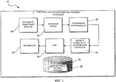
На фиг.1 показана блок-схема сопряжения системы отслеживания (мониторинга) частичных разрядов (ОЧР) согласно одному из примеров осуществления, взаимодействующей с высоковольтной трехфазной электрической или энергетической системой,Figure 1 shows the block diagram of the pairing system for tracking (monitoring) partial discharges (BCH) according to one example of implementation, interacting with a high-voltage three-phase electrical or energy system,
на фиг.2 - более подробная функциональная блок-схема системы ОЧР, показанной на фиг.1,figure 2 is a more detailed functional block diagram of the OFDM system shown in figure 1,
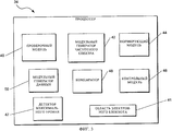
на фиг.3 - более подробная функциональная блок-схема процессора системы ОЧР, показанной на фиг.2,figure 3 is a more detailed functional block diagram of the processor of the OFDM system shown in figure 2,
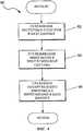
на фиг.4 - блок схема способа согласно одному из примеров осуществления,figure 4 is a block diagram of a method according to one embodiment,
на фиг.5 - другая блок схема способа согласно одному из примеров осуществления,5 is another block diagram of a method according to one embodiment,
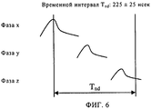
на фиг.6 - наглядное представление импульсов, возникающих в течение определенного временного интервала, в основном с целью проиллюстрировать характеристики распознавания шума описанной системы ОЧР,Fig.6 is a visual representation of the pulses that occur during a certain time interval, mainly with the aim of illustrating the characteristics of the noise recognition of the described OFDM system,
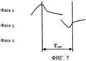
на фиг.7 - наглядное представление импульсов, возникающих в течение определенного временного интервала, в основном с целью проиллюстрировать один из примеров перекрестных помех,7 is a visual representation of the pulses that occur during a certain time interval, mainly with the aim of illustrating one example of crosstalk,
на фиг.8 - другое наглядное представление импульсов, возникающих в течение определенного временного интервала, в основном с целью проиллюстрировать один из примеров перекрестных помех,on Fig - another visual representation of the pulses that occur during a certain time interval, mainly with the aim of illustrating one example of crosstalk,
на фиг.9 - другое наглядное представление импульсов, возникающих в течение определенного временного интервала, в основном с целью проиллюстрировать один из примеров перекрестных помех,figure 9 is another visual representation of pulses that occur during a certain time interval, mainly with the aim of illustrating one example of crosstalk,
на фиг.10 - другое наглядное представление импульсов, возникающих в течение определенного временного интервала, в основном с целью проиллюстрировать один из примеров перекрестных помех,figure 10 is another visual representation of the pulses that occur during a certain time interval, mainly with the aim of illustrating one example of crosstalk,
на фиг.11 - один из примеров диаграммы разброса, генерированной системой ОЧР, проиллюстрированной на фиг.2,figure 11 is one example of a scatter diagram generated by the OFDM system illustrated in figure 2,
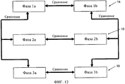
на фиг.12 - функциональная блок-схема дискриминации входных импульсов,on Fig is a functional block diagram of the discrimination of the input pulses,
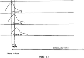
на фиг.13 - наглядное представление импульсов, возникающих в течение определенного временного интервала, в основном с целью проиллюстрировать шумовой импульс, обнаруживаемый во всех трех фазах,on Fig - a visual representation of the pulses that occur during a certain time interval, mainly with the aim of illustrating the noise pulse detected in all three phases,
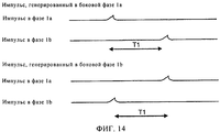
на фиг.14 - наглядное представление распределения по времени импульсов, возникающих в любой из фаз 1а и 1b, как показано на фиг.1,on Fig is a visual representation of the time distribution of pulses arising in any of the phases 1A and 1b, as shown in figure 1,
на фиг.15 - наглядное представление возможной частотной характеристики в каждой полосе,on Fig is a visual representation of the possible frequency response in each band,
на фиг.16 - иллюстрация справочной таблицы согласно одному из примеров осуществления,in Fig.16 is an illustration of a lookup table according to one embodiment,
на фиг.17 - иллюстрация диаграммы разброса для определенного числа импульсов с известным спектром, который хранится в базе данных, построенной способом усреднения значений максимального уровня каждой из частотных составляющих для каждого последующего сходного импульса,on Fig - illustration of a scatter chart for a certain number of pulses with a known spectrum, which is stored in a database constructed by averaging the maximum level values of each of the frequency components for each subsequent similar pulse,
на фиг.18 - иллюстрация диаграммы разброса для импульса с неизвестным спектром (который не хранится в базе данных, показанной на фиг.2), построенной способом усреднения значений максимального уровня каждой из частотных составляющих для каждого последующего сходного импульса,in Fig.18 is an illustration of a scatter diagram for a pulse with an unknown spectrum (which is not stored in the database shown in Fig.2), constructed by averaging the maximum level values of each of the frequency components for each subsequent similar pulse,
на фиг.19 - высокоуровневая блок-схема обработки импульса,on Fig is a high-level block diagram of the pulse processing,
на фиг.20 - один из примеров возможного общего числа диаграмм разброса,in Fig.20 is one example of a possible total number of dispersion patterns,
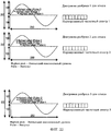
на фиг.21 - один из примеров диаграмм разброса для спектров из справочной таблицы иon Fig - one of the examples of scatter diagrams for spectra from a look-up table and
на фиг.22 - один из примеров диаграмм разброса для новых спектров.on Fig - one of the examples of scatter diagrams for new spectra.
Описание предпочтительных вариантов осуществленияDescription of Preferred Embodiments
В следующем далее описании в целях пояснения приведено множество конкретных подробностей, обеспечивающих полное понимание вариантов осуществление настоящего изобретения. Тем не менее для специалистов в данной области техники ясно, что настоящее изобретение может быть реализовано на практике без этих конкретных подробностей.In the following description, for purposes of explanation, numerous specific details are set forth in order to provide a thorough understanding of embodiments of the present invention. However, it will be apparent to those skilled in the art that the present invention may be practiced without these specific details.
Показанная на фиг.1-3 система мониторинга или отслеживания частичных разрядов (ОЧР) согласно одному из примеров осуществления в целом обозначена позицией 10. Система 10 ОЧР посредством датчиков 20 коммуникативно связана с высоковольтной электрической или энергораспределительной системой 12, например трехфазной системой распределения электроэнергии. Каждый датчик 20 обычно представляет собой конденсатор или заземляющий резистор или, иными словами, однополюсный высокочастотный фильтр. В одном из примеров осуществления предусмотрена пара датчиков 20 для каждой фазы 14, 16 и 18 трехфазной энергетической системы 12, в результате чего система 10 ОЧР имеет шесть каналов. Пара датчиков 20 отдельной фазы 14, 16 или 18 может использоваться, чтобы определять направление перемещения события в фазе 14, 16 или 18, что подробнее будет описано далее.1 to 3, a partial discharge monitoring or tracking system (PMD) according to one embodiment is generally indicated by 10. The
Система 10 ОЧР также связана с хост-компьютером 22, для чего на физическом уровне канала передачи данных необязательно используется USB2. При этом система ОЧР 22 может быть способной действовать в автономном режиме, т.е. без подключенного компьютера 22, тем не менее при последующем подключении компьютера 22 к системе 10 ОЧР компьютер 22 и система 10 ОЧР могут при желании обмениваться данными. В одном из примеров осуществления система 10 ОЧР соединяется с хост-компьютером 22 при его включении, чтобы установить регистры при необходимости изменения значений по умолчанию, а также, чтобы позволить хост-компьютеру 22 начать сбор данных. Тем не менее следует отметить, что после начала работы системы 10 ОЧР она будет продолжать действовать, как если бы хост-компьютер 22 был выключен. При последующем восстановлении соединения с хост-компьютером 22 модуль управления (не показан) хост-компьютера 22 будет обновлен любыми необходимыми данными из системы 10 ОЧР.The
Следует отметить, что система 10 ОЧР обычно синхронизирована с переходом сети через нулевой уровень.It should be noted that the
В одном из примеров осуществления в систему 10 ОЧР входит множество компонентов или модулей, которые соответствуют функциональным задачам, выполняемым системой 10 ОЧР. При этом подразумевается, что "модуль" в контексте настоящего описания содержит идентифицируемую часть кода, вычислительных или выполняемых команд, данных или вычислительного объекта для выполнения конкретной функции, операции, обработки или процедуры.In one embodiment, the
Следовательно, модуль необязательно должен быть реализован программными средствами; модуль может быть реализован программными средствами, аппаратными средствами или путем сочетания программных и аппаратных средств. Кроме того, модули необязательно должны быть объединены в одно устройство и могут быть распределены среди множества устройств.Therefore, the module does not have to be implemented in software; a module may be implemented in software, hardware, or by a combination of software and hardware. In addition, the modules do not have to be combined into a single device and can be distributed among multiple devices.
В частности, система 10 ОЧР содержит входной защитный модуль 24, обеспечивающий защиту каждого канала от перенапряжений и сверхтоков. В одном из примеров осуществления система 10 ОЧР содержит входной буфер 26. Входной буфер 26 обычно представляет собой высокоимпедансный аналоговый буфер с импедансом, превышающим 1 мегом.In particular, the
В системе 10 ОЧР также предусмотрен усилитель 28 напряжения, обычно программируемый усилитель напряжения. Программируемый усилитель 28 напряжения обычно имеет полосу частот шириной 270 МГц. Следует учесть, что после включения системы 10 ОЧР усиление всех датчиков 20 устанавливается на уровень минимальной чувствительности.In the
Система 10 ОЧР дополнительно содержит фильтр 30 защиты от наложения спектров с частотой отсечки около 270 МГц, неравномерностью затухания 0,5 дБ и затуханием в полосе задержания 54 дБ.The
В одном из примеров осуществления система 10 ОЧР содержит 8-разрядный аналого-цифровой преобразователь (АЦП) 32 с частотой дискретизации 800 МГц.In one embodiment, the
Как показано на фиг.16, система 10 ОЧР содержит базу 36 данных, в которой может храниться по меньшей мере множество спектров отказов. В одном из примеров осуществления в базе 36 данных хранится справочная таблица 38 спектров отказов (фиг.16), в которой содержится информация о множестве спектров отказов. В справочной таблице 38 описаны известные отказы и шумы. Справочная таблица 38 является расширяемой за счет как предварительно заданных спектров отказов, так и спектров отказов, которые становятся известны системе 10. В одном из примеров осуществления каждая спектральная составляющая, хранящаяся в таблице 38 спектров отказов, может содержать десять разрядов, в частности знаковый разряд, один разряд для хранения значения, равного 1,0, и 8-разрядную мантиссу, что позволяет хранить числа в интервале от -0,99549375 до 1,00000000. Может быть предусмотрен отказобезопасный вход с максимальным ограничением 216-1, т.е. 2 байта. Таким образом, в каждой строке таблицы 38 спектров отказов содержится 100 разрядов. Следует учесть, что таблица 38 спектров отказов может быть организована таким образом, что доступ для чтения и записи могут осуществляться одновременно. Тем не менее в ситуации доступа для чтения и записи данных, размещенных по одному адресу, приоритет отдается доступу для чтения.As shown in FIG. 16, the
Система 10 ОЧР также имеет процессор 34 (подробнее показан на фиг.3) для обеспечения дополнительных функциональных задач, в частности задач обработки сигналов, выполняемых системой 10 ОЧР. При этом следует учесть, что процессор 34 также может содержать множество функциональных модулей, соответствующих функциям, которые должен осуществлять процессор 34. Из приведенного выше описания модулей следует, что модули или, в частности, функциональные возможности модулей процессора 34 необязательно должны быть реализованы в процессоре 34 и необязательно могут быть реализованы в системе 10 ОЧР. В одном из примеров осуществления процессор 34 представляет собой программируемую пользователем вентильную матрицу (FPGA).The
Следует учесть, что процессор 34 рассматривает данные, исходя из временных интервалов, в частности трех временных интервалов, а именно, кванта времени, вспомогательного временного интервала и основного временного интервала. Квантом времени обычно является временной интервал, равный 80 µсек. Квант времени представляет собой разрешающую способность по оси времени в многомерных массивах, используемых для хранения собранных данных. Вспомогательный временной интервал обычно имеет длительность 20 мсек (что соответствует одному циклу на частоте 50 Гц). Из этого следует, что вспомогательный временной интервал состоит из 250 квантов времени. Основным временным интервалом является период, за который происходит агрегирование данных, при этом он обычно содержит определяемое пользователем или запрограммированное число вспомогательных временных интервалов. Например, основной временной интервал может содержать минимально один вспомогательный временной интервал и максимально 500 вспомогательных временных интервалов.It should be noted that the
Как показано на фиг.3, процессор 34 содержит проверочный модуль 40. В других примерах осуществления проверочный модуль 40 реализован отдельно от процессора 34. Проверочный модуль 40 способен осуществлять проверку достоверности импульсов входного сигнала. Таким образом, проверочный модуль 40 способен сравнивать фазы 14, 16 и 18, как показано на фиг.12. В частности, проверочный модуль 40 способен осуществлять три процесса, которые необходимы для проверки достоверности входного импульса в ходе процесса проверки достоверности. Обычно этими процессами являются определение направления перемещения принятого входного импульса, распознавание шума и проверка перекрестных помех. Два последних процесса осуществляются после того, как определено направление перемещения входного импульса, при этом в них используется первый из поступивших входных импульсов. Кроме того, при осуществлении двух последних процессов проверочный модуль 40 сравнивает фазы 1а, 2а и 3а (и аналогичным образом фазы 1b, 2b и 3b), как показано на фиг.12. Система 10 ОЧР необязательно содержит модуль распознавания шума (не показан) для осуществления или оказания содействия проверочному модулю 40 в осуществлении описанного распознавания шума. Из этого следует, что для обнаружения или определения направления перемещения импульса проверочный модуль 40 сравнивает фазы 1а с 1b, 2а с 2b и 3а с 3b.As shown in FIG. 3, the
Подразумевается, что для определения направления перемещения проверочный модуль 40 определяет время прихода входного импульса согласно показаниям обоих датчиков 20 для каждой фазы 14, 16 и 18. Если время перемещения меньше запрограммированного времени Тtr распространения, проверочный модуль 40 игнорирует импульс. Тем не менее, если время перемещения превышает запрограммированное время Тtr распространения, проверочный модуль 40 определяет, на какой датчик 20 пришел первый импульс, и какой флаг будет выставлен или переустановлен, чтобы указать направление прихода импульса. Например:It is understood that to determine the direction of movement, the
флаг 0: от датчика а,flag 0: from sensor a,
флаг 1: от датчика b (как показано на фиг.14, на которой Тtr=Т1).flag 1: from sensor b (as shown in FIG. 14, on which T tr = T1).
Флаг может использоваться, чтобы определять, какая группа из 16 должна быть обновлена. При этом процессор 34 содержит модульный генератор 50 данных, служащий для обновления или генерации диаграмм, которыми в одном из примеров осуществления могут являться диаграммы разброса и т.п. Следует отметить, что модульный генератор 50 данных способен генерировать данные, касающиеся принятого или обнаруженного импульса, которые могут использоваться для создания диаграмм разброса на основании подмножества спектров отказов принятого или обнаруженного импульса (что рассмотрено далее). На фиг.11 проиллюстрирован один из примеров диаграммы разброса, генерированной модульным генератором 50 данных (для всех зарегистрированных импульсов).A flag can be used to determine which group of 16 should be updated. At the same time, the
Модульный генератор 50 данных способен генерировать отдельную диаграмму разброса, иллюстрирующую все обнаруженные импульсы в соответствующем кванте времени. Генерированные диаграммы разброса хранятся в базе 36 данных, в которой диаграммы разброса, соответствующие отказам, связаны с соответствующими отказами.The
Из этого следует, что время распространения может выбираться в определенных пределах, в частности, минимальное время Тtrmin распространения может составлять 10 нсек, а максимальное время Тtrmax распространения может составлять 250 нсек.It follows that the propagation time can be selected within certain limits, in particular, the minimum propagation time T trmin can be 10 nsec, and the maximum propagation time T trmax can be 250 nsec.
Что касается определения направления перемещения, следует отметить, что для каждой боковой фазы 1а и 1b, 2а и 2b и 3а и 3b фаз 14, 16 и 18 соответственно предусмотрен датчик 20. На фиг.14 проиллюстрирована фаза 14 с соответствующими боковыми фазами 1а и 1b, если датчиком 20 в установленный период, например, Т1 первым обнаружен импульс со сходным спектральным составом в боковой фазе 1а, и, следовательно, импульс поступает от боковой фазы 1а. Импульс, поступающий от боковой фазы 1а, запоминается или сохраняется, а импульс, поступивший от боковой фазы 1b, отбрасывается. Тем не менее, если в установленный период, Т1 первым обнаружен импульс со сходным спектральным составом, поступивший от боковой фазы 1b, импульс, поступивший от боковой фазы 1b, запоминается или сохраняется, а импульс, поступивший от боковой фазы 1а, отбрасывается. Как описано выше, если импульсы возникают в течение меньшего промежутка времени, чем установленный период Т1, они поступают в интервале между точками обнаружения и, соответственно, отбрасываются, следовательно, периодом Т1 является описанный выше период Ttr.As for determining the direction of movement, it should be noted that for each
Что касается распознавания шума, проверочный модуль 40 способен определять, имеет ли место в течение заданного временного интервала Tnd входной импульс с одинаковой полярностью в двух или более фазах 14, 16 или 18, показанных на фиг.6 (в данном случае боковые фазы 1а, 2а и 3а обозначены как X, Y и Z соответственно). Если это так, проверочный модуль 40 рассматривает входной импульс как шум и, следовательно, игнорирует его. Из фиг.12 следует, что проверочный модуль 40 способен сравнивать фазы, например, 1а, 2а и 3а друг с другом с целью принятия решения. Как показано на фиг.13, из этого следует, что с целью обнаружения шума проверочный модуль 40 определяет, имеют ли импульсы в фазах 1а, 2а и 3а сходные максимальные уровни амплитуд, сходный спектральный состав или одинаковую полярность. Процессор 34 имеет детектор 47 максимального уровня для определения значений максимального уровня импульсов. В одном из примеров осуществления проверочный модуль 40 использует детектор 47 максимального уровня, чтобы определять, имеют ли импульсы сходный максимальный уровень амплитуд. Кроме того, проверочный модуль 40 способен определять, возникают ли все импульсы на протяжении перекрывающих периодов простоя, а также, находится ли время прихода в ограниченном интервале (в пределах текущего числа тактовых циклов). Из этого следует, что при обнаружении импульсов этого типа они могут рассматриваться как внешний шум и, соответственно, отбрасываться.With regard to noise recognition, the
Перекрестные помехи могут возникать только между двумя фазами 14, 16 или 18 или между всеми тремя фазами 14, 16 и 18 энергетической системы 12. Если проверочный модуль 40 определяет или обнаруживает, что в течение заданного временного интервала в одной из фаз, например 1а, возник импульс, а в любой из двух других фаз 2а или 3а возник импульс с противоположной полярностью, как показано на фиг.7 (в данном случае фазы 1а, 2а и 3а проиллюстрированы как X, Y и Z соответственно), проверочный модуль 40 способен игнорировать второй импульс, поскольку он создает перекрестные помехи с другой фазой (2а или 3а). При этом временной интервал может задаваться пользователем или программироваться в определенных пределах. Например, минимальный временной интервал ТCC перекрестных помех может составлять 250 нсек, а максимальный временной интервал ТCC перекрестных помех может составлять 2000 нсек. Для принятия описанного решения проверочный модуль 40 определяет, имеют ли импульсы различные максимальные уровни амплитуд, сходный спектральный состав, имеют ли два обнаруженных импульсы противоположные полярности и возникают ли оба импульса на протяжении перекрывающих периодов простоя.Crosstalk can occur only between two
Проверочный модуль 40 также способен определять или обнаруживать, возникает ли импульс в одной фазе, например 1а, а также, возникает ли импульс с противоположной полярностью в обеих их фазах 2а и 3а, например, в течение заданного перекрывающего временного интервала, как это показано на фиг.8 (в данном случае фазы 1а, 2а и 3а проиллюстрированы как X, Y и Z соответственно). В этих обстоятельствах проверочный модуль 40 способен игнорировать оба импульса с противоположной полярностью и разрешать обработку только первого импульса.
Проверочный модуль 40 способен определять, создаются ли перекрестные помехи между входными импульсами в двух фазах путем определения наличия различных максимальных уровней амплитуд, сходного спектрального состава импульсов, противоположной полярности импульсов, а также возникают ли все импульсы на протяжении перекрывающих периодов простоя. Если установлено, что первым возникает импульс с противоположной полярностью, импульсы могут считаться создающими перекрестные помехи. Если это так, этот конкретный импульс сохраняют, а остальные два импульса отбрасывают, в противном случае сохраняют все импульсы. Вместо этого или дополнительно необязательно запоминают все три импульса.The
Проверочный модуль 40 дополнительно способен определять или обнаруживать, возникает ли импульс в одной фазе, например 1а, и определять или обнаруживать, возникает ли импульс с такой же полярность в одной из двух фаз 2а или 3а в течение заданного временного интервала. Проверочный модуль также способен обнаруживать или определять, возникает ли импульс с противоположной полярностью в третьей фазе 3а, например фазе 18, в течение заданного перекрывающего временного интервала, как это показано на фиг.9 (в данном случае фазы 1а, 2а и 3а проиллюстрированы как X, Y и Z соответственно). Согласно этому сценарию проверочный модуль 40 игнорирует импульс с противоположной полярностью, т.е. третий импульс, возникающий в третьей фазе 3а (или Z), и разрешает обработку только двух других импульсов в фазах 1а и 2а (X и Y). Оба импульса обычно обрабатывают как отдельные события.The
Аналогичным образом проверочный модуль 40 способен определять или обнаруживать, возникает ли импульс в одной фазе, например 1а, и возникает ли импульс с противоположной полярностью в одной из двух фаз 2а или 3а в течение заданного временного интервала. Если импульс с такой же полярностью возникает первым в третьей фазе, скажем фазе 3а, в течение заданного перекрывающего временного интервала, как это показано на фиг.10, проверочный модуль 40 игнорирует импульс с противоположной полярностью, т.е. возникающий вторым импульс, и дополнительно разрешает обработку только двух других импульсов в качестве отдельных событий.Similarly, the
На этом этапе необходимо учитывать скорости обмена данными между процессами, и в связи с этим следует упомянуть, что при использовании для проверки достоверности широкополосного канального фильтра информацией, переносимой из фазовых процессов в процессы распознавания шума и проверки перекрестных помех, будет являться амплитуда и полярность для каждой полосы из гребенки фильтров, флаг, указывающий, данные какого датчика 20 фазы 14, 16 или 18 были собраны, и разрешающая способность по времени от последнего перехода через нулевой уровень до 5 нсек. Обычно на полосу фильтра приходится 10 битов данных, а на отметку времени 22 бита. Таким образом, всего используется 113 битов. Кроме того, минимальное разнесение событий составляет 100 нсек. Следовательно, максимальная требуемая скорость передачи данных не будет составлять не более 1,13 Гбит/сек (113 битов за 100 нсек).At this stage, it is necessary to take into account the data exchange rates between the processes, and in this connection it should be mentioned that when using the wide-band channel filter to verify the accuracy of the information transferred from the phase processes to the noise recognition and crosstalk verification processes, the amplitude and polarity will be bands from the filter bank, a flag indicating which sensor data 20
В одном из примеров осуществления, процессор 34 содержит модульный генератор частотного спектра 42, способный генерировать частотный спектр проверенного входного импульса. Следует учесть, что проверенным входным импульсом является входной импульс, обработка которого разрешена проверочным модулем 40. В модульном генераторе 42 частотного спектра обычно имеются или используются гребенки фильтров для генерации частотного спектра проверенного входного импульса. Как показано на фиг.15, каждая гребенка фильтров обычно представляет собой гребенку из любого числа фильтров от одного и более. В качестве примера и для ясности в данном случае проиллюстрировано восемь фильтров для каждого канала, однако может использоваться любое число гребенок фильтров от одной и более. Обычно фильтры представляют собой полосовые фильтры с фиксированной шириной полосы. В одном из примеров осуществления, ни одна из полос фильтров не перекрывает какую-либо другую полосу. Каждая высокочастотная точка отсечки - 3 дБ согласована с низкочастотной точкой отсечки -3 дБ следующих полос. Обычно самая низкая по частоте точка отсечки самого низкочастотного фильтра составляет не менее 100 кГц.In one embodiment, the
За счет того что фильтры реализованы как фильтры с конечной импульсной характеристикой (КИХ), для специалистов в данной области техники подразумевается, что полоса частот фильтров определяется как диапазон частот, в котором характеристика отвечает требованию к неравномерности затухания. При этом неравномерность затухания фильтров обычно составляет 0,5 дБ, а затухание в полосе задержания фильтров предпочтительно составляет 55 дБ. Полосы описанных фильтров приведены далее в Таблице 1.Due to the fact that the filters are implemented as filters with a finite impulse response (FIR), it is understood by those skilled in the art that the frequency band of the filters is defined as the frequency range in which the characteristic meets the requirement for non-uniform attenuation. In this case, the filter attenuation non-uniformity is usually 0.5 dB, and the filter attenuation in the filter delay band is preferably 55 dB. The bands of the described filters are shown below in Table 1.
Каждая гребенка фильтров дополнительно содержит комплексный смеситель для понижающего преобразования входного импульса, фильтр нижних частот (реализованный в виде КИХ-фильтра) и блок децимации для снижения частоты дискретизации данных до приемлемой скорости обработки. Следует учесть, что может быть необязательно предусмотрен девятый широкополосный канал.Each filter bank additionally contains a complex mixer for down-converting the input pulse, a low-pass filter (implemented as an FIR filter) and a decimation unit to reduce the data sampling rate to an acceptable processing speed. Note that a ninth broadband channel may not necessarily be provided.
В одном из примеров осуществления сохраняют значение максимального уровня для каждой из восьми полос для дальнейшей обработки. Затем восемь значений максимального уровня нормируют (как будет описано далее) к виду наибольшего значения максимального уровня, и сохраняют наибольшее значение максимального уровня вместе с восемью нормализованными значениями для дальнейшей обработки.In one embodiment, a maximum level value is stored for each of the eight bands for further processing. Then, eight values of the maximum level are normalized (as will be described later) to the form of the highest value of the maximum level, and the highest value of the maximum level is stored together with eight normalized values for further processing.
При этом процессор 34 также содержит нормирующий модуль 44, способный нормировать частотный спектр или значения максимального уровня, полученные от модульного генератора 42 частотного спектра, к виду максимального уровня в спектре, чтобы тем самым получить нормированный спектр. В одном из примеров осуществления, нормированные значения максимального уровня сохраняют в справочной таблице 38 известных отказов.At the same time, the
Из этого следует, что процессор 34 также содержит контрольный модуль 46. Контрольный модуль 46 посредством датчиков 20 способен отслеживать интересующие импульсы, возникающие в энергетической системе 12. Контрольный модуль 46 может быть способен выполнять алгоритм определения максимального уровня, что будет описано далее. Вместе с тем, следует учесть, что контрольный модуль 46 также может отвечать за отслеживание обработки импульса после его приема или обнаружения.It follows that the
В одном из предпочтительных вариантов осуществления процессор 34 содержит компаратор 48, способный сравнивать частотный спектр, генерированный для проверенного входного импульса, с существующими спектрами отказов, хранящимися в базе 36 данных, в частности в таблице 38 спектров отказов, чтобы по меньшей мере устанавливать наличие преимущественного соответствия генерированного частотного спектра проверенного импульса любому из существующих спектров отказов. Из этого следует, что в компараторе 48 используется нормированный спектральный состав импульса для сравнения с содержимым справочной таблицы 38. Для выполнения этой функции в компараторе 48 может использоваться определяемый пользователем показатель эквивалентности. В одном из примеров осуществления компаратор 48 способен применять алгоритм сопоставления отказов, чтобы сравнивать частотный спектр, генерированный для проверенного импульса, с существующими спектрами отказов, хранящимися в таблице 38 спектров отказов. Алгоритм сопоставления отказов обычно представляет собой сумму квадратов разностей согласно следующему уравнению:In one preferred embodiment, the
сумма квадратов разностей ![]()
![]()
в котором xk,n означает составляющую n строки k, yn означает n-ю спектральную составляющую нормированного спектра.in which x k, n means the component n of the string k, y n means the n-th spectral component of the normalized spectrum.
Следует учесть, что, если генерированный частотный спектр преимущественно соответствует любому из существующих спектров отказов, процессор 34 способен выставлять флаг, сигнализирующий об этом. Помимо выставления флага процессор 34 способен извлекать из базы 36 данных диаграмму разброса, соответствующую отказу (что подробнее рассмотрено далее). В одном из примеров осуществления флагом является дескриптор отказов. В других примерах осуществления флаг может позволять системе 10 ОЧР генерировать дескриптор отказов. Тем не менее, если генерированный частотный спектр преимущественно не соответствует ни одному из существующих спектров отказов, процессор 34 способен сохранять данные или генерированный частотный спектр проверенного импульса в таблице 38 спектров отказов базы 36 данных помимо выставления флага с этой целью. Для ясности дескриптором отказов обычно является дескриптор, содержащий информацию с указанием по меньшей мере номера отказа, которым является 8-разрядное число, амплитуды импульса, которой является 8-разрядное число, выведенное на основании данных фазы и амплитуды из упомянутой девятой полосы, отметки времени, которой является 8-разрядное число, содержащее квант времени во вспомогательном временном интервале, в который возник импульс, информации о фазе, которой является двухразрядное число, указывающее, в какой из фаз 14, 16 или 18 произошло событие отказа, информации о датчике 20, которой является 1-разрядное число, указывающее, по данным какого датчика 20 фазы 14, 16 или 18 было зарегистрировано событие, и флага, которым является одноразрядный флаг с состоянием, изменяющимся после каждого основного временного интервала.It should be noted that if the generated frequency spectrum predominantly corresponds to any of the existing failure spectra, the
В одном из примеров осуществления в случае соответствия спектра известному спектру из справочной таблицы 38 значение максимального уровня, соответствующее такому спектру, вносят в диаграмму разброса для этого спектра или, если диаграмма разброса отсутствует, модульный генератор 50 данных генерирует новую диаграмму разброса. Если в диаграмме разброса содержатся параметры сигнала, нормированные спектры этого сигнала добавляют к спектрам отказов, а если в ней содержится параметры шума, их добавляют к спектрам шумов. Это способствует обучению системы 10 ОЧР.In one embodiment, if the spectrum matches the known spectrum from look-up table 38, the maximum level value corresponding to such a spectrum is entered into the scatter chart for that spectrum or, if there is no scatter chart, the
Как показано на фиг.17, если входной импульс или, иными словами, генерированный частотный спектр импульса соответствует спектру известного отказа и для этого конкретного спектра отсутствует диаграмма разброса, модульный генератор 50 данных способен генерировать новую диаграмму разброса для отказа. Соответственно, сохраненный нормированный частотный спектр отказа соотносят с генерированной диаграммой разброса и сохраняют в базе 36 данных вместе с диаграммой разброса. Значение максимального уровня для спектра импульса помещают в соответствующий ему квант времени на диаграмме разброса. Кроме того, генерированный частотный спектр также усредняют с использованием спектра известного отказа, для чего ведут учет числа импульсов (счет импульсов) на конкретной диаграмме разброса. По мере возникновения новых импульсов со сходными частотными спектрами их добавляют к диаграмме разброса. По мере добавления новых импульсов суммарный нормированный частотный спектр, соответствующий диаграмме разброса, усредняют согласно следующему уравнению:As shown in FIG. 17, if the input pulse or, in other words, the generated frequency spectrum of the pulse corresponds to the spectrum of a known fault and there is no scatter pattern for this particular spectrum, the
(нормированный спектр отказа + общее число всех остальных сходных спектров)/(счет импульсов + 1).(normalized failure spectrum + total number of all other similar spectra) / (pulse count + 1).
Как показано на фиг.18, если генерированный частотный спектр импульса преимущественно не соответствует ни одному из спектров известных отказов и для генерированного спектра отсутствуют диаграммы разброса, модульный генератор 50 данных генерирует новую диаграмму разброса. Значение максимального уровня для спектра импульса помещают в соответствующий ему квант времени на диаграмме разброса. Следует отметить, что для этого ведут учет числа импульсов (счет импульсов) на диаграмме разброса. По мере возникновения новых импульсов со сходными частотными спектрами их добавляют к диаграмме разброса. Следует учесть, что для этого нормированные спектры новых импульсов сравнивают как с таблицей 38 спектров отказов, так и с генерированными спектрами импульсов, еще не сохраненными в таблице 38 спектров отказов. По мере добавления новых импульсов усредняют суммарный нормированный частотный спектр, соответствующий диаграмме разброса. Процесс усреднения представлен следующим уравнением:As shown in FIG. 18, if the generated frequency spectrum of the pulse mainly does not correspond to any of the known failure spectra and there are no scatter patterns for the generated spectrum, the
(общее число всех сходных спектров)/(счет импульсов).(total number of all similar spectra) / (pulse count).
Если в одном из примеров осуществления измеренное число импульсов постоянно, например, в течение 10-секудного периода, превышает 10 импульсов за цикл, явление импульсов может интерпретироваться как шум. Импульсы с максимальным уровнем перемещают в диаграмму разброса для всех зарегистрированных импульсов. Нормированные спектры сохраняют в таблице 38 спектров отказов как шум. После того как это сделано, соответствующую диаграмму разброса отбрасывают.If in one embodiment, the measured number of pulses is constant, for example, over a 10 second period, exceeds 10 pulses per cycle, the phenomenon of pulses can be interpreted as noise. Pulses with a maximum level are moved to the scatter plot for all recorded pulses. The normalized spectra are stored in table 38 of the failure spectra as noise. After this is done, the corresponding scatter pattern is discarded.
Следует учесть, что, если измеренное число импульсов постоянно, например, в течение 10-секудного периода составляет менее 10 импульсов за цикл, явление импульсов может интерпретироваться как известный отказ. Нормированные спектры сохраняют в таблице 38 спектров отказов как спектры отказов. Следует учесть, что при этом диаграмму разброса сохраняют в базе 36 данных и сопоставляют с известным отказом.It should be noted that if the measured number of pulses is constant, for example, during a 10-second period, is less than 10 pulses per cycle, the phenomenon of pulses can be interpreted as a known failure. The normalized spectra are stored in a table of 38 failure spectra as failure spectra. It should be noted that in this case, the scatterplot is stored in the
Если в результате сравнения со спектрами шумов из справочной таблицы 38 импульс идентифицирован как шумовой импульс, значение максимального уровня для спектра импульса помещают в соответствующий ему квант времени на диаграмме разброса для всех зарегистрированных импульсов.If, as a result of comparison with the noise spectra from the look-up table 38, the impulse is identified as a noise impulse, the maximum level value for the impulse spectrum is placed in the corresponding time quantum on the scatter diagram for all detected impulses.
В одном из предпочтительных примеров осуществления процессор 34 имеет электронный блокнот или область 41 электронного блокнота. Область 41 электронного блокнота используется для хранения числа событий конкретного спектра отказа во вспомогательном временном интервале и для каждой полосы суммы уровней нарастающим итогом в этой полосе на основании нормированного спектра. В одном из примеров осуществления в области 41 электронного блокнота ведется счет импульсов, как это описано ранее. Из этого следует, что при выставлении флага, когда компаратор 48 обнаруживает преимущественное соответствие, в области 41 электронного блокнота может быть увеличено число событий конкретного отказа. В одном из примеров осуществления область 41 электронного блокнота может служить удобной платформой для манипуляций с диаграммой разброса, как это описано выше.In one preferred embodiment, the
Следует учесть, что таблицу 38 спектров отказов обычно обновляют новыми спектральными данными импульса всякий раз при отсутствии преимущественного соответствия между генерированным частотным спектром этого импульса и спектрами из таблицы 38 спектров отказов. Из этого следует, что при каждом соединении хост-компьютера 22 с системой 10 ОЧР таблица 38 спектров отказов переносится в хост-компьютер 22. При этом, если на вспомогательный временной интервал максимально приходится лишь двадцать отказов, во вспомогательный временной интервал может быть перенесено до двадцати дескрипторов отказов (28-разрядных), и, таким образом, максимальная скорость передачи данных для дескрипторов отказов будет составлять 28 кбит/сек. Когда все дескрипторы отказов относятся к различным отказам, во вспомогательный временной интервал переносится до двадцати обновлений таблицы спектров отказов (104-разрядных), и, таким образом, максимальная скорость передачи данных для обновлений таблицы спектров отказов будет составлять 104 кбит/сек. При указанных выше скоростях передачи данных максимальная скорость передачи данных посредством USB от системы 10 ОЧР хост-компьютеру 22 обычно составляет 132 кбит/сек.It should be noted that the table 38 of the failure spectra is usually updated with new spectral data of the pulse whenever there is no predominant correspondence between the generated frequency spectrum of this pulse and the spectra from the table 38 of the failure spectra. From this it follows that at each connection of the host computer 22 with the
Наконец, рассмотрим фиг.19. Процессор 34 принимает входной импульс или сигнал. Процессор 34 распределяет сигнал между восемью полосами частот. Каждой полосе частот соответствует максимальный уровень. Восемь полос частот образуют частотный спектр. Этот частотный спектр нормируют и сохраняют наибольшее значение максимального уровня вместе с восемью нормированными значениями частотного спектра. Восемь полос частот используются лишь в качестве иллюстрации, и может использоваться любое число полос частот от одной и более.Finally, consider FIG. 19. The
Нормированный частотный спектр сравнивают с определенным числом предварительно заданных частотных спектров, которые хранятся в справочной таблице 38. Если спектр соответствует спектрам из справочной таблице 38, на диаграмме разброса, которая соответствует обнаруженному частотному спектру, отображается значение максимального уровня. Если соответствие отсутствует, создается новая диаграмма разброса.The normalized frequency spectrum is compared with a certain number of predefined frequency spectra that are stored in look-up table 38. If the spectrum corresponds to the spectra in look-up table 38, the maximum level value is displayed on the scatter plot that corresponds to the detected frequency spectrum. If there is no match, a new scatter chart is created.
Что касается показанных на фиг.20-22 диаграммам разброса, на фиг.20 проиллюстрировано общее число диаграмм разброса, необходимых для диаграммы разброса каждого типа. В частности, на фиг.20 показаны десять диаграмм разброса из справочной таблицы 38 (это может быть любое число от одного и более), пять диаграмм разброса для новых спектров (это может быть любое число от одного и более), и одна диаграмма разброса для всех импульсов.As for the scatter patterns shown in FIGS. 20-22, FIG. 20 illustrates the total number of scatter patterns needed for each type of scatter chart. In particular, FIG. 20 shows ten scatter patterns from look-up table 38 (this can be any number from one or more), five scatter patterns for new spectra (it can be any number from one or more), and one scatter chart for all impulses.
На фиг.21 проиллюстрирован пример диаграмм разброса для спектров из справочной таблицы 38, а на фиг.22 показаны диаграммы разброса для новых спектров.FIG. 21 illustrates an example of scatter patterns for spectra from look-up table 38, and FIG. 22 shows scatter patterns for new spectra.
Далее будет описано применение примеров осуществления со ссылкой на фиг.4-7. Примеры способа, проиллюстрированного на фиг.4 и 5, описаны со ссылкой на фиг.1-3, хотя следует учесть, что примеры способа также могут быть применимы в других системах (не проиллюстрированных).Next, application of the embodiments will be described with reference to FIGS. Examples of the method illustrated in FIGS. 4 and 5 are described with reference to FIGS. 1-3, although it should be noted that examples of the method may also be applicable to other systems (not illustrated).
Рассмотрим фиг.4, на которой показана блок-схема способа, в целом обозначенного позицией 60, согласно одному из примеров осуществления. Способ 60 включает шаг 62, на котором сохраняют множество спектров отказов в базе 36 данных, в частности, в таблице 38 спектров отказов базы 36 данных. Обычно этот шаг является предварительным шагом, на котором в таблице 38 спектров отказов сохраняют спектры отказов или спектральные составляющие данных, соответствующих известным спектрам отказов.Consider figure 4, which shows a block diagram of a method generally indicated by 60, according to one embodiment. The
Способ 60 дополнительно включает шаг 64, на котором отслеживают энергетическую систему 12 с целью приема или обнаружения возникающих в ней сигналов или импульсов. Для краткости следует учесть, что прием сигнала или импульса или связанной с ним информации может подразумевать обнаружение сигнала или импульса. Это может осуществляться посредством контрольного модуля 46. В частности, следует учесть, что входные импульсы изначально обнаруживают путем использования алгоритма обнаружения максимального уровня, реализованного посредством контрольного модуля 46. Обычно используются два параметра, связанных с обнаружением максимального уровня, при этом оба из них определяются пользователем. Обнаружение максимального уровня, реализованное посредством контрольного модуля 46, идентично аналоговому режиму слежения и запоминания с переустановкой, т.е. выходной сигнал детектора максимального уровня будет соответствовать входному сигналу, пока текущий входной сигнал превышает предыдущий входной сигнал, в противном случае он будет сохранять ранее достигнутое максимальное значение. Чтобы детектор максимального уровня мог возобновить режим слежения, предусмотрена переустановка. Двумя определяемыми пользователем параметрами являются абсолютный порог, который должен превысить входной сигнал, чтобы его можно было объявить потенциальным максимальным уровнем, и окно обнаружения максимального уровня, которое устанавливает, как долго сохраненное значение оставаться должно в нем не превышенным, пока не будет объявлено максимальным уровнем. После того как объявлен максимальный уровень, контрольный модуль 46 возобновляет режим слежения и запоминания.The
Значение окна обнаружения максимального уровня задает абсолютную максимальную скорость объявления достоверных максимальных уровней. В одном из примеров осуществления окно обнаружения максимального уровня обычно составляет 1,5 цсек. Это значит, что абсолютная максимальная скорость объявления достоверных максимальных уровней обычно составляет 13333 за 20 мсек, при этом большинство из максимальных уровней является шумом. Из этого следует, что, если у детектора максимального уровня будет установлен порог, превышающий минимальный уровень шума, число достоверных максимальных уровней существенно снизится.The value of the maximum level detection window sets the absolute maximum speed of the declaration of reliable maximum levels. In one embodiment, the maximum level detection window is typically 1.5 csec. This means that the absolute maximum speed for declaring reliable maximum levels is usually 13333 in 20 ms, with most of the maximum levels being noise. From this it follows that if a threshold is set at the maximum level detector that exceeds the minimum noise level, the number of reliable maximum levels will be significantly reduced.
После того как импульс обнаружен, может осуществляться шаг 66 способа 60, на котором с помощью компаратора 48 сравнивают генерированный частотный спектр обнаруженного импульса с существующими спектрами отказов, хранящимися в таблице 38 спектров отказов, чтобы по меньшей мере устанавливать наличие преимущественного соответствия генерированного частотного спектра обнаруженного импульса любому из существующих спектров отказов (как описано далее). Для специалистов в данной области техники ясно, что для того, чтобы компаратор 48 осуществлял предусмотренное сравнение, обнаруженный входной импульс сначала обрабатывается проверочным модулем 40 с целью проверки достоверности импульса, как это описано выше. Затем проверенный импульс нормируют с помощью нормирующего модуля 44. Наконец, перед сравнением на шаге 66 с помощью модульного генератора частотного спектра генерируют частотный спектр проверенного импульса 42, чтобы способствовать сравнению, предусмотренному на шаге 66.Once an impulse is detected, step 66 of
Рассмотрим фиг.5, на которой показана блок-схема другого способа, в целом обозначенного позицией 70, согласно одному из примеров осуществления. Поскольку первые три шага способа 70 сходны с тремя шагами, описанными выше со ссылкой на фиг.4, для их обозначения будут использованы такие же соответствующие позиции.Consider figure 5, which shows a block diagram of another method, generally indicated at 70, according to one embodiment. Since the first three steps of
В способе 70 более подробно представлены исходы осуществления шага сравнения, т.е. шага 66. В частности, на шаге 72 способа 70 определяют наличие преимущественного соответствия генерированного частотного спектра обнаруженного импульса любому из существующих спектров отказов, хранящихся в таблице 38 спектров отказов. Следует отметить, что для осуществления этого сравнения в компараторе 48 реализован алгоритм сопоставления отказов, как это описано выше. Если частотный спектр обнаруженного импульса преимущественно соответствует любому из существующих спектров отказов, в способе может быть предусмотрено выставление флага, чтобы сигнализировать об этом (как будет описано далее). В частности, если обнаружено соответствие, затем на шаге 74 способа 70 определяют, содержатся ли в области 41 электронного блокнота отказы этого конкретного типа. Если в области 41 электронного блокнота содержатся отказы этого конкретного типа, на шаге 78 способа 70 концентрируют этот конкретный спектр в области 41 электронного блокнота и увеличивают число событий этого конкретного спектра. Тем не менее, если спектр отсутствует в области 41 электронного блокнота, на шаге 76 способа 70 в области 41 электронного блокнота создают новую запись для этого конкретного спектра.
Тем не менее, если между частотным спектром обнаруженного импульса и существующими спектрами отказов отсутствует преимущественное соответствие, способ 70 предусматривает выставление флага, чтобы сигнализировать об этом (как будет пояснено далее). В частности, если на шаге 74 не обнаружено преимущественное соответствие и конкретный спектр обнаруженного импульса отсутствует в области 41 электронного блокнота, на шаге 82 способа 70 создают новую запись в области 41 электронного блокнота и помечают спектр обнаруженного импульса как новый спектр отказа. Следует учесть, что на шаге 82 создают новую запись в базе 36 данных для нового обнаруженного отказа.However, if there is no predominant match between the frequency spectrum of the detected pulse and the existing failure spectra,
Помимо этого, следует отметить, что для каждого отказа, обнаруженного во вспомогательном временном интервале, определяют среднее значение спектральных точек, собранных за этот временной интервал. Кроме того, если отказ уже содержится в таблице 38 спектров отказов, вычисляют общее среднее значение спектральных точек. Из этого следует, что таблицу 38 спектров отказов периодически обновляют этими новыми средними значениями. При обновлении отказа новую запись необязательно передают хост-компьютеру 22 для хранения дубликата таблицы 38 спектров отказов. Данные, соответствующие отказу, обычно содержат номер отказа (8-разрядное число), значения восьми спектральных составляющих (в общей сложности 80 разрядов) и номер значения накопления (16-разрядное число).In addition, it should be noted that for each failure detected in the auxiliary time interval, determine the average value of the spectral points collected for this time interval. In addition, if the failure is already contained in the table 38 failure spectra, calculate the total average value of the spectral points. It follows that the table 38 of the failure spectra is periodically updated with these new averages. When updating a failure, a new record is optionally transferred to the host computer 22 for storing a duplicate table 38 of the failure spectra. The data corresponding to the failure usually contains the failure number (8-bit number), the values of eight spectral components (a total of 80 bits) and the accumulation value number (16-bit number).
Затем на шаге 80 способа 70 выставляют или генерируют флаг в форме дескриптора отказов, как это описано выше применительно к соответствующим исходам. Следует учесть, что в этом частном примере осуществления при выставлении флага генерируют дескриптор отказов, как это описано выше. В других примерах осуществления выставление флага может предусматривать оповещение персонала о наличии или отсутствии соответствия посредством предупредительного сигнала и т.п.Then, at step 80 of
Следует учесть, что этим способом отслеживают и анализируют обнаруживаемые в энергетической системе импульсы, что позволяет удобно определять их характеристики отказа.It should be noted that in this way the pulses detected in the energy system are monitored and analyzed, which makes it possible to conveniently determine their failure characteristics.
В описанном изобретении предложен удобный способ мониторинга частичных разрядов, происходящих в трехфазных энергетических системах. Путем спектрального анализа с целью обнаружения частичных разрядов могут быть по меньшей мере смягчены или даже предотвращены нежелательные исходы, сопутствующие частичным разрядам.The described invention provides a convenient method for monitoring partial discharges occurring in three-phase energy systems. By spectral analysis to detect partial discharges, undesirable outcomes associated with partial discharges can be at least mitigated or even prevented.
Claims (10)
принимают импульс от электрической системы; идентифицируют, является ли импульс шумом или дублированным сигналом;
если импульс является шумом или дублированным сигналом, тогда этот импульс отбрасывают;
разбивают импульс на две или более частотные составляющие; нормализуют эти две или более частотные составляющие к виду максимального уровня;
сравнивают две или более нормализованные частотные составляющие, связанные с принятым импульсом, с другим сохраненным множеством нормализованных, предварительно заданных частотных составляющих, связанных с другими импульсами, для идентифицирования сходных импульсов, указывающих известное состояние отказа;
если импульс идентифицирован как импульс, указывающий известное состояние отказа, сохраняют данные в базе данных, связывая импульс с двумя или более нормализованными частотными составляющими и известным состоянием отказа;
группируют спектр отказов импульсов со сходными нормализованными частотными составляющими в диаграмме разброса, сохраняемой в базе данных;
если нормализованные частотные составляющие импульса не сходны с нормализованными частотными составляющими текущей группы, создают новую группу спектра отказов импульсов, сохраняемую в базе данных; и
если импульс идентифицирован как указывающий известное состояние отказа, уведомляют пользователя о наличии состояния отказа.1. A method for monitoring partial discharges in an electrical system, in which:
receive a pulse from the electrical system; identify whether the pulse is a noise or a duplicate signal;
if the pulse is noise or a duplicated signal, then this pulse is discarded;
break the pulse into two or more frequency components; normalize these two or more frequency components to the maximum level view;
comparing two or more normalized frequency components associated with the received pulse, with another stored set of normalized, predefined frequency components associated with other pulses, to identify similar pulses indicating a known failure state;
if the pulse is identified as a pulse indicating a known failure state, data is stored in the database, linking the pulse to two or more normalized frequency components and a known failure state;
grouping the spectrum of pulse failures with similar normalized frequency components in a scatter diagram stored in a database;
if the normalized frequency components of the pulse are not similar to the normalized frequency components of the current group, create a new group of the spectrum of failure pulses stored in the database; and
if the impulse is identified as indicating a known failure state, notify the user of the failure state.
базу данных для хранения множества спектров отказов; контрольный модуль для отслеживания приема электрической системой импульсов;
аналого-цифровой преобразователь для преобразования импульса из аналогового в цифровой сигнал;
проверочный модуль для проверки достоверности принятого импульса путем идентифицирования, является ли импульс шумом или дублированным сигналом;
детектор максимального уровня для определения значения максимального уровня принятого импульса;
модульный генератор частотного спектра, способный генерировать частотный спектр импульса, полученного контрольным модулем, путем разбития импульса на две или более частотные составляющие;
нормирующий модуль, служащий для нормирования значений максимального уровня каждой из предварительно заданных двух или более частотных составляющих принятого импульса к виду максимального уровня; компаратор, выполненный с возможностью после приема импульса: сравнивать две или более нормализованные частотные составляющие, связанные с принятым импульсом, с другим сохраненным множеством нормализованных предварительно заданных частотных составляющих, связанных с другими импульсами, для идентифицирования сходных импульсов, указывающих известное состояние отказа;
если импульс идентифицирован как импульс, указывающий известное состояние отказа, сохранять данные в базе данных, связывая импульс с двумя или более нормализованными частотными составляющими и известным состоянием отказа;
группировать спектр отказов импульсов со сходными нормализованными частотными составляющими в диаграмме разброса, сохраняемой в базе данных;
если нормализованные частотные составляющие импульса не сходны с нормализованными частотными составляющими текущей группы, создавать новую группу спектра отказов импульсов, сохраняемую в базе данных; и устройство для отображения точки, представляющей максимальный уровень принятого импульса, на диаграмме разброса вместе с точками, представляющими другие идентифицированные сходные максимальные уровни импульса.6. A system for monitoring partial discharges in an electrical system, comprising:
a database for storing multiple failure spectra; a control module for monitoring the reception of impulses by the electrical system;
analog-to-digital converter for converting a pulse from an analog to a digital signal;
a test module for checking the reliability of the received pulse by identifying whether the pulse is noise or a duplicated signal;
a maximum level detector for determining a value of a maximum level of a received pulse;
a modular frequency spectrum generator capable of generating the frequency spectrum of a pulse received by a control module by breaking the pulse into two or more frequency components;
a normalizing module that serves to normalize the values of the maximum level of each of the predefined two or more frequency components of the received pulse to the form of the maximum level; a comparator configured to, after receiving the pulse: compare two or more normalized frequency components associated with the received pulse with another stored set of normalized predefined frequency components associated with other pulses, to identify similar pulses indicating a known failure state;
if the pulse is identified as a pulse indicating a known failure state, save the data in the database by linking the pulse to two or more normalized frequency components and the known failure state;
group the spectrum of pulse failures with similar normalized frequency components in the scatter diagram stored in the database;
if the normalized frequency components of the pulse are not similar to the normalized frequency components of the current group, create a new group of the pulse failure spectrum stored in the database; and a device for displaying a point representing the maximum level of the received pulse on the scatter chart along with points representing other identified similar maximum pulse levels.
Applications Claiming Priority (3)
| Application Number | Priority Date | Filing Date | Title |
|---|---|---|---|
| ZA200806804 | 2008-08-06 | ||
| ZA2008/06804 | 2008-08-06 | ||
| PCT/IB2009/053174 WO2010015958A1 (en) | 2008-08-06 | 2009-07-22 | Partial discharge monitoring method and system |
Publications (2)
| Publication Number | Publication Date |
|---|---|
| RU2011108221A RU2011108221A (en) | 2012-09-20 |
| RU2532142C2 true RU2532142C2 (en) | 2014-10-27 |
Family
ID=41327352
Family Applications (1)
| Application Number | Title | Priority Date | Filing Date |
|---|---|---|---|
| RU2011108221/28A RU2532142C2 (en) | 2008-08-06 | 2009-07-22 | Method and system to monitor partial discharges |
Country Status (13)
| Country | Link |
|---|---|
| US (1) | US9229042B2 (en) |
| EP (1) | EP2321661B1 (en) |
| JP (1) | JP5536061B2 (en) |
| AU (1) | AU2009278834B2 (en) |
| CA (1) | CA2732918C (en) |
| DK (1) | DK2321661T3 (en) |
| ES (1) | ES2467673T3 (en) |
| MX (1) | MX2011001358A (en) |
| PT (1) | PT2321661E (en) |
| RU (1) | RU2532142C2 (en) |
| UA (1) | UA104429C2 (en) |
| WO (1) | WO2010015958A1 (en) |
| ZA (1) | ZA200905123B (en) |
Families Citing this family (19)
| Publication number | Priority date | Publication date | Assignee | Title |
|---|---|---|---|---|
| DK2324364T3 (en) * | 2008-08-25 | 2012-08-13 | Eskom Holdings Ltd | Partial discharge monitor |
| ES2379831A1 (en) * | 2010-05-26 | 2012-05-04 | Universidad Politécnica de Madrid | METHOD FOR THE CONTINUOUS MONITORING AND DIAGNOSIS OF SOURCES OF PARTIAL DISCHARGES (PDs) IN HIGH-VOLTAGE CABLES DURING CONNECTION TO, AND OPERATION IN THE POWER GRID, AND PHYSICAL SYSTEM FOR CARRYING OUT SAME |
| CA2821795C (en) * | 2010-12-30 | 2020-07-07 | Prysmian S.P.A. | Locating of partial-discharge-generating faults |
| DE102012217497A1 (en) * | 2012-09-26 | 2014-03-27 | Airbus Operations Gmbh | A method of detecting a noise generating device in an electrical network, an electrical system, and an aircraft |
| CN103197206A (en) * | 2013-03-12 | 2013-07-10 | 重庆市电力公司电力科学研究院 | Electrical level scanning type ultrahigh frequency partial discharge on-line monitoring system and monitoring method |
| CN103197213A (en) * | 2013-03-29 | 2013-07-10 | 国家电网公司 | Partial discharge measurement system |
| JP6507767B2 (en) * | 2015-03-23 | 2019-05-08 | 日立金属株式会社 | Method of measuring partial discharge, partial discharge measuring device, and method of manufacturing insulated wire |
| GB2537113B (en) * | 2015-04-01 | 2018-05-23 | High Voltage Partial Discharge Ltd | Apparatus and method for monitoring partial discharge |
| US11307264B2 (en) * | 2016-06-14 | 2022-04-19 | Schweitzer Engineering Laboratories, Inc. | Phase selection for traveling wave fault detection systems |
| CN106771893B (en) * | 2016-11-22 | 2019-02-19 | 三峡大学 | A kind of ground insulator gap discharge method for waveform identification |
| WO2019195532A1 (en) | 2018-04-04 | 2019-10-10 | Schneider Electric USA, Inc. | Systems and methods for intelligent alarm grouping |
| EP3899560A4 (en) * | 2018-12-19 | 2022-07-27 | ABB Schweiz AG | Method and system for condition monitoring electrical equipment |
| CN111880051B (en) * | 2020-05-29 | 2021-11-09 | 西安交通大学 | Gas pulse discharge parameter measuring method and device |
| US20230176105A1 (en) * | 2020-07-15 | 2023-06-08 | Mitsubishi Electriic Corporation | Insulation defect detection method and detection system for magnet wire coating, manufacturing method for electric machine, and electric machine |
| EP3961227A1 (en) * | 2020-08-31 | 2022-03-02 | General Electric Company | Online and offline partial discharge detection for electrical drive systems |
| CN112446320B (en) * | 2020-11-23 | 2022-03-29 | 广东电网有限责任公司 | Fuzzy recognition logic gate multiple complementary partial discharge distinguishing device and method |
| CZ309279B6 (en) * | 2021-01-18 | 2022-07-13 | Modemtec S.R.O. | A method of signal extraction and a device for this |
| CN113848435B (en) * | 2021-08-31 | 2023-12-15 | 四川大学 | Direct-current partial discharge signal classification and identification method based on frequency spectrum energy distribution probability |
| CN116699335B (en) * | 2023-06-16 | 2024-03-08 | 广州友智电气技术有限公司 | Partial discharge monitoring method and system for high-voltage power equipment |
Citations (3)
| Publication number | Priority date | Publication date | Assignee | Title |
|---|---|---|---|---|
| JPH0712880A (en) * | 1993-06-28 | 1995-01-17 | Toshiba Corp | Partial discharge detection method |
| JPH07159477A (en) * | 1993-12-07 | 1995-06-23 | Furukawa Electric Co Ltd:The | Method for measuring partial discharge from power cable line |
| US5982181A (en) * | 1996-12-09 | 1999-11-09 | Hitachi, Ltd. | Insulated device diagnosing system for diagnosing device based upon partial discharge signal data analyzed by frequency |
Family Cites Families (26)
| Publication number | Priority date | Publication date | Assignee | Title |
|---|---|---|---|---|
| US5214595A (en) * | 1988-05-16 | 1993-05-25 | Hitachi, Ltd. | Abnormality diagnosing system and method for a high voltage power apparatus |
| JPH0664108B2 (en) * | 1989-06-02 | 1994-08-22 | 株式会社日立製作所 | Diagnostic apparatus and diagnostic method for power equipment |
| JPH0750147B2 (en) * | 1989-06-14 | 1995-05-31 | 株式会社日立製作所 | Abnormal position locating method and apparatus for gas insulated electrical equipment |
| JP2641588B2 (en) * | 1990-03-09 | 1997-08-13 | 株式会社日立製作所 | Power equipment and its abnormal location method |
| JPH04204270A (en) * | 1990-11-30 | 1992-07-24 | Toshiba Corp | Partial-discharge detecting device for gas insulation switching device |
| US5272439A (en) * | 1992-02-21 | 1993-12-21 | University Of Connecticut | Method and apparatus for the detection and location of faults and partial discharges in shielded cables |
| US5578931A (en) * | 1993-10-15 | 1996-11-26 | The Texas A & M University System | ARC spectral analysis system |
| JPH08105928A (en) | 1994-10-05 | 1996-04-23 | Takaoka Electric Mfg Co Ltd | Partial discharge strength measuring device |
| DE4441334C1 (en) * | 1994-11-08 | 1996-07-11 | Siemens Ag | Method for determining the location of a fault in a predetermined monitoring area of a multi-phase electrical power transmission line system |
| US5570028A (en) * | 1994-12-30 | 1996-10-29 | Lucent Technologies Inc. | Method for detecting faults in electrical cables and apparatus for implementing same |
| US6809523B1 (en) * | 1998-10-16 | 2004-10-26 | The Detroit Edison Company | On-line detection of partial discharge in electrical power systems |
| DE19848636C2 (en) * | 1998-10-22 | 2001-07-26 | Fraunhofer Ges Forschung | Method for monitoring an AC voltage discharge on a double electrode |
| US6291979B1 (en) * | 1999-02-16 | 2001-09-18 | Advantest Corporation | Apparatus for and method of detecting a delay fault |
| US6377184B1 (en) * | 2000-04-11 | 2002-04-23 | Gary A. Minker | Transmission line safety monitoring system |
| US6369582B2 (en) * | 2000-05-04 | 2002-04-09 | Georgia Tech Research Corporation | System and method for off-line impulse frequency response analysis test |
| US6930610B2 (en) * | 2002-05-03 | 2005-08-16 | General Electric Company | Monitoring system and method for wiring systems |
| AU2003234448A1 (en) * | 2002-05-06 | 2003-11-11 | Enikia Llc | Method and system for power line network fault detection and quality monitoring |
| FR2855878B1 (en) | 2003-06-05 | 2005-08-05 | Alstom | METHOD FOR DETECTING PARTIAL DISCHARGES AND DIAGNOSTIC SYSTEM FOR ELECTRICAL APPARATUS |
| WO2005038475A1 (en) * | 2003-10-22 | 2005-04-28 | Fujikura Ltd. | Insulation degradation diagnosis apparatus |
| AU2005273202B2 (en) * | 2004-08-20 | 2009-05-21 | Kabushiki Kaisha Toshiba | Device and method for detecting partial discharge of rotary electric machine |
| US7532012B2 (en) * | 2006-07-07 | 2009-05-12 | Ambient Corporation | Detection and monitoring of partial discharge of a power line |
| JP4860795B2 (en) * | 2006-09-07 | 2012-01-25 | 三菱電機株式会社 | Power equipment |
| US7579843B2 (en) * | 2006-10-13 | 2009-08-25 | General Electric Company | Methods and apparatus for analyzing partial discharge in electrical machinery |
| US7676333B2 (en) * | 2007-11-06 | 2010-03-09 | General Electric Company | Method and apparatus for analyzing partial discharges in electrical devices |
| US7750646B2 (en) * | 2008-01-10 | 2010-07-06 | General Electric Company | Detector for precursive detection of electrical arc |
| US8143899B2 (en) * | 2008-04-01 | 2012-03-27 | General Electric Company | Method and apparatus for detecting partial discharges in electrical systems |
-
2009
- 2009-07-22 CA CA2732918A patent/CA2732918C/en active Active
- 2009-07-22 AU AU2009278834A patent/AU2009278834B2/en active Active
- 2009-07-22 UA UAA201102397A patent/UA104429C2/en unknown
- 2009-07-22 ZA ZA200905123A patent/ZA200905123B/en unknown
- 2009-07-22 US US13/057,712 patent/US9229042B2/en active Active
- 2009-07-22 EP EP09786665.1A patent/EP2321661B1/en active Active
- 2009-07-22 JP JP2011521661A patent/JP5536061B2/en active Active
- 2009-07-22 DK DK09786665.1T patent/DK2321661T3/en active
- 2009-07-22 ES ES09786665.1T patent/ES2467673T3/en active Active
- 2009-07-22 PT PT97866651T patent/PT2321661E/en unknown
- 2009-07-22 WO PCT/IB2009/053174 patent/WO2010015958A1/en active Application Filing
- 2009-07-22 MX MX2011001358A patent/MX2011001358A/en active IP Right Grant
- 2009-07-22 RU RU2011108221/28A patent/RU2532142C2/en active
Patent Citations (3)
| Publication number | Priority date | Publication date | Assignee | Title |
|---|---|---|---|---|
| JPH0712880A (en) * | 1993-06-28 | 1995-01-17 | Toshiba Corp | Partial discharge detection method |
| JPH07159477A (en) * | 1993-12-07 | 1995-06-23 | Furukawa Electric Co Ltd:The | Method for measuring partial discharge from power cable line |
| US5982181A (en) * | 1996-12-09 | 1999-11-09 | Hitachi, Ltd. | Insulated device diagnosing system for diagnosing device based upon partial discharge signal data analyzed by frequency |
Also Published As
| Publication number | Publication date |
|---|---|
| AU2009278834A1 (en) | 2010-02-11 |
| CA2732918C (en) | 2017-12-05 |
| CA2732918A1 (en) | 2010-02-11 |
| US9229042B2 (en) | 2016-01-05 |
| JP5536061B2 (en) | 2014-07-02 |
| WO2010015958A1 (en) | 2010-02-11 |
| MX2011001358A (en) | 2011-08-03 |
| JP2011530080A (en) | 2011-12-15 |
| RU2011108221A (en) | 2012-09-20 |
| US20110248721A1 (en) | 2011-10-13 |
| ZA200905123B (en) | 2010-05-26 |
| AU2009278834B2 (en) | 2014-06-05 |
| DK2321661T3 (en) | 2014-05-26 |
| EP2321661A1 (en) | 2011-05-18 |
| PT2321661E (en) | 2014-04-07 |
| UA104429C2 (en) | 2014-02-10 |
| ES2467673T3 (en) | 2014-06-12 |
| EP2321661B1 (en) | 2014-03-05 |
Similar Documents
| Publication | Publication Date | Title |
|---|---|---|
| RU2532142C2 (en) | Method and system to monitor partial discharges | |
| EP1094323B1 (en) | Method and system for identifying cause of partial discharge | |
| CN105606977B (en) | Shelf depreciation PRPS spectrum recognition method and system based on hierarchical rule reasoning | |
| US20180031626A1 (en) | Method and device to identify, record and store traveling wave heads in electric power systems | |
| US6507181B1 (en) | Arrangement and method for finding out the number of sources of partial discharges | |
| EP1094324B1 (en) | Method and arrangement for defining location of partial discharge sources | |
| CN104598342B (en) | The detection method and device of memory | |
| EP3206574A1 (en) | Frame based spike detection module | |
| EP2183608B1 (en) | Instrument and a method for detecting partial electrical discharges occurring in an electric apparatus | |
| US8008925B2 (en) | Electrical partial discharge pulse marker discrimination | |
| CN106019089A (en) | Method for carrying out partial discharging determination based on related relationship feature of alternate signals | |
| AU2018203705A1 (en) | Testing of defibrillator electrodes | |
| US11742651B2 (en) | Systems and methods for arc fault detection built-in-test | |
| CN102901953A (en) | Correlated peak sharpening method and device | |
| Koo et al. | A possible application of the PD detection technique using electro-optic Pockels cell with nonlinear characteristic analysis on the PD signals | |
| JP2877347B2 (en) | Partial cable discharge detection method | |
| CN113504438B (en) | Method and device for detecting insulation resistance of column head cabinet and column head cabinet | |
| Ofodile et al. | Modelling the recovery of pulse peak pileup for implementation in an FPGA for a nuclear spectroscopy system | |
| CN106405295A (en) | State detection method, apparatus and system of distribution terminal analog input channel | |
| CZ202120A3 (en) | A method of signal extraction and a device for this | |
| JPH01314973A (en) | Surge classifying circuit | |
| CN117473385A (en) | Fault arc identification method, device, equipment and medium | |
| RO133581A2 (en) | Automatic survey of magnetic field with detection and characterization of transient fields |