RU2531725C2 - Output device and replaceable element - Google Patents
Output device and replaceable element Download PDFInfo
- Publication number
- RU2531725C2 RU2531725C2 RU2011124521/12A RU2011124521A RU2531725C2 RU 2531725 C2 RU2531725 C2 RU 2531725C2 RU 2011124521/12 A RU2011124521/12 A RU 2011124521/12A RU 2011124521 A RU2011124521 A RU 2011124521A RU 2531725 C2 RU2531725 C2 RU 2531725C2
- Authority
- RU
- Russia
- Prior art keywords
- valve
- annular wall
- replaceable
- cap
- replaceable element
- Prior art date
Links
Images


Classifications
-
- B—PERFORMING OPERATIONS; TRANSPORTING
- B67—OPENING, CLOSING OR CLEANING BOTTLES, JARS OR SIMILAR CONTAINERS; LIQUID HANDLING
- B67D—DISPENSING, DELIVERING OR TRANSFERRING LIQUIDS, NOT OTHERWISE PROVIDED FOR
- B67D3/00—Apparatus or devices for controlling flow of liquids under gravity from storage containers for dispensing purposes
-
- A—HUMAN NECESSITIES
- A47—FURNITURE; DOMESTIC ARTICLES OR APPLIANCES; COFFEE MILLS; SPICE MILLS; SUCTION CLEANERS IN GENERAL
- A47K—SANITARY EQUIPMENT NOT OTHERWISE PROVIDED FOR; TOILET ACCESSORIES
- A47K5/00—Holders or dispensers for soap, toothpaste, or the like
- A47K5/06—Dispensers for soap
- A47K5/12—Dispensers for soap for liquid or pasty soap
- A47K5/1217—Electrical control means for the dispensing mechanism
-
- A—HUMAN NECESSITIES
- A47—FURNITURE; DOMESTIC ARTICLES OR APPLIANCES; COFFEE MILLS; SPICE MILLS; SUCTION CLEANERS IN GENERAL
- A47K—SANITARY EQUIPMENT NOT OTHERWISE PROVIDED FOR; TOILET ACCESSORIES
- A47K5/00—Holders or dispensers for soap, toothpaste, or the like
- A47K5/06—Dispensers for soap
- A47K5/12—Dispensers for soap for liquid or pasty soap
- A47K5/1202—Dispensers for soap for liquid or pasty soap dispensing dosed volume
-
- B—PERFORMING OPERATIONS; TRANSPORTING
- B65—CONVEYING; PACKING; STORING; HANDLING THIN OR FILAMENTARY MATERIAL
- B65D—CONTAINERS FOR STORAGE OR TRANSPORT OF ARTICLES OR MATERIALS, e.g. BAGS, BARRELS, BOTTLES, BOXES, CANS, CARTONS, CRATES, DRUMS, JARS, TANKS, HOPPERS, FORWARDING CONTAINERS; ACCESSORIES, CLOSURES, OR FITTINGS THEREFOR; PACKAGING ELEMENTS; PACKAGES
- B65D47/00—Closures with filling and discharging, or with discharging, devices
- B65D47/04—Closures with discharging devices other than pumps
- B65D47/20—Closures with discharging devices other than pumps comprising hand-operated members for controlling discharge
- B65D47/2018—Closures with discharging devices other than pumps comprising hand-operated members for controlling discharge comprising a valve or like element which is opened or closed by deformation of the container or closure
- B65D47/2031—Closures with discharging devices other than pumps comprising hand-operated members for controlling discharge comprising a valve or like element which is opened or closed by deformation of the container or closure the element being formed by a slit, narrow opening or constrictable spout, the size of the outlet passage being able to be varied by increasing or decreasing the pressure
-
- B—PERFORMING OPERATIONS; TRANSPORTING
- B65—CONVEYING; PACKING; STORING; HANDLING THIN OR FILAMENTARY MATERIAL
- B65D—CONTAINERS FOR STORAGE OR TRANSPORT OF ARTICLES OR MATERIALS, e.g. BAGS, BARRELS, BOTTLES, BOXES, CANS, CARTONS, CRATES, DRUMS, JARS, TANKS, HOPPERS, FORWARDING CONTAINERS; ACCESSORIES, CLOSURES, OR FITTINGS THEREFOR; PACKAGING ELEMENTS; PACKAGES
- B65D47/00—Closures with filling and discharging, or with discharging, devices
- B65D47/04—Closures with discharging devices other than pumps
- B65D47/20—Closures with discharging devices other than pumps comprising hand-operated members for controlling discharge
- B65D47/24—Closures with discharging devices other than pumps comprising hand-operated members for controlling discharge with poppet valves or lift valves, i.e. valves opening or closing a passageway by a relative motion substantially perpendicular to the plane of the seat
- B65D47/248—Closures with discharging devices other than pumps comprising hand-operated members for controlling discharge with poppet valves or lift valves, i.e. valves opening or closing a passageway by a relative motion substantially perpendicular to the plane of the seat the valve being opened or closed by imparting a motion to the valve stem
-
- B—PERFORMING OPERATIONS; TRANSPORTING
- B65—CONVEYING; PACKING; STORING; HANDLING THIN OR FILAMENTARY MATERIAL
- B65D—CONTAINERS FOR STORAGE OR TRANSPORT OF ARTICLES OR MATERIALS, e.g. BAGS, BARRELS, BOTTLES, BOXES, CANS, CARTONS, CRATES, DRUMS, JARS, TANKS, HOPPERS, FORWARDING CONTAINERS; ACCESSORIES, CLOSURES, OR FITTINGS THEREFOR; PACKAGING ELEMENTS; PACKAGES
- B65D47/00—Closures with filling and discharging, or with discharging, devices
- B65D47/36—Closures with frangible parts adapted to be pierced, torn, or removed, to provide discharge openings
-
- B—PERFORMING OPERATIONS; TRANSPORTING
- B65—CONVEYING; PACKING; STORING; HANDLING THIN OR FILAMENTARY MATERIAL
- B65D—CONTAINERS FOR STORAGE OR TRANSPORT OF ARTICLES OR MATERIALS, e.g. BAGS, BARRELS, BOTTLES, BOXES, CANS, CARTONS, CRATES, DRUMS, JARS, TANKS, HOPPERS, FORWARDING CONTAINERS; ACCESSORIES, CLOSURES, OR FITTINGS THEREFOR; PACKAGING ELEMENTS; PACKAGES
- B65D55/00—Accessories for container closures not otherwise provided for
- B65D55/02—Locking devices; Means for discouraging or indicating unauthorised opening or removal of closure
- B65D55/024—Closures in which a part has to be ruptured to gain access to the contents
-
- F—MECHANICAL ENGINEERING; LIGHTING; HEATING; WEAPONS; BLASTING
- F16—ENGINEERING ELEMENTS AND UNITS; GENERAL MEASURES FOR PRODUCING AND MAINTAINING EFFECTIVE FUNCTIONING OF MACHINES OR INSTALLATIONS; THERMAL INSULATION IN GENERAL
- F16L—PIPES; JOINTS OR FITTINGS FOR PIPES; SUPPORTS FOR PIPES, CABLES OR PROTECTIVE TUBING; MEANS FOR THERMAL INSULATION IN GENERAL
- F16L37/00—Couplings of the quick-acting type
- F16L37/28—Couplings of the quick-acting type with fluid cut-off means
- F16L37/38—Couplings of the quick-acting type with fluid cut-off means with fluid cut-off means in only one of the two pipe-end fittings
- F16L37/40—Couplings of the quick-acting type with fluid cut-off means with fluid cut-off means in only one of the two pipe-end fittings with a lift valve being opened automatically when the coupling is applied
- F16L37/413—Couplings of the quick-acting type with fluid cut-off means with fluid cut-off means in only one of the two pipe-end fittings with a lift valve being opened automatically when the coupling is applied the lift valve being of the sleeve type, i.e. a sleeve being telescoped over an inner cylindrical wall
-
- B—PERFORMING OPERATIONS; TRANSPORTING
- B65—CONVEYING; PACKING; STORING; HANDLING THIN OR FILAMENTARY MATERIAL
- B65D—CONTAINERS FOR STORAGE OR TRANSPORT OF ARTICLES OR MATERIALS, e.g. BAGS, BARRELS, BOTTLES, BOXES, CANS, CARTONS, CRATES, DRUMS, JARS, TANKS, HOPPERS, FORWARDING CONTAINERS; ACCESSORIES, CLOSURES, OR FITTINGS THEREFOR; PACKAGING ELEMENTS; PACKAGES
- B65D2401/00—Tamper-indicating means
- B65D2401/15—Tearable part of the closure
Abstract
Description
Настоящее изобретение относится к устройству выдачи для выдачи жидкого мыла или подобного.The present invention relates to a dispenser for dispensing liquid soap or the like.
Устройство выдачи имеет блок основания, в который сменный элемент, содержащий материал для выдачи, установлен в перевернутом положении, то есть его выпускное отверстие расположено на самом нижнем конце. Настоящее изобретение было специально сконструировано для отдельно стоящего устройства выдачи мыла, подходящего для использования в бытовой среде. Однако оно также может быть применено к установленному на стене устройству и может использоваться в более крупных устройствах, таких как публичные туалеты. Устройство может иметь управляемый вручную насос для выдачи жидкости, но предпочтительно снабжено датчиком приближения, который распознает присутствие руки пользователя, и имеет насос для автоматической выдачи жидкости.The dispensing device has a base unit in which a replaceable element containing the dispensing material is installed in an inverted position, that is, its outlet is located at the lowermost end. The present invention has been specifically designed for a stand-alone soap dispenser suitable for use in a domestic environment. However, it can also be applied to a wall-mounted device and can be used in larger devices such as public toilets. The device may have a manually controlled pump for dispensing liquid, but is preferably equipped with a proximity sensor that detects the presence of a user's hand and has a pump for automatically dispensing liquid.
Поскольку устройство главным образом предназначено для бытового рынка, важно, чтобы потребитель мог заменить сменный элемент способом, который очень прост, имеет защиту от неумелого обращения и не создает беспорядка, который в лучшем случае вызывает раздражение потребителя и в худшем случае может разрушить механизм выдачи.Since the device is mainly intended for the domestic market, it is important that the consumer can replace the replacement element in a way that is very simple, has protection against inept handling and does not create a mess that, at best, causes consumer irritation and in the worst case can destroy the dispensing mechanism.
Согласно настоящему изобретению, устройство выдачи содержит блок основания с приводным механизмом для выдачи жидкости и сменный элемент, вставляемый в блок основания в перевернутом положении, причем его выпускное отверстие расположено в самом низу для подачи жидкости в основание, причем сменный элемент содержит кольцевую стенку, выступающую в сменный элемент и образующую выпускное отверстие из сменного элемента, причем кольцевая стенка выполнена с возможностью закрытия на ее наиболее внутреннем конце элементом клапана, смещенным на кольцевую стенку, причем основание содержит полую втулку и кольцевое уплотнение, окружающее и отстоящее от верхней части втулки, за счет чего установка сменного элемента в основание вызывает введение втулки в кольцевую стенку и подъем элемента клапана от кольцевой стенки, чтобы образовать канал потока из сменного элемента, через, по меньшей мере, один вырез, образованный в верхней части втулки и/или нижней части элемента клапана и вниз по полой втулке, и кольцевое уплотнение для уплотнения между втулкой и кольцевой стенкой.According to the present invention, the dispensing device comprises a base unit with a drive mechanism for dispensing liquid and an interchangeable element inserted into the base unit in an inverted position, the outlet opening thereof being located at the very bottom for supplying liquid to the base, the interchangeable element comprising an annular wall protruding into interchangeable element and forming an outlet from the interchangeable element, and the annular wall is made with the possibility of closure at its innermost end by a valve element, offset by a ring wall, the base comprising a hollow sleeve and an annular seal surrounding and spaced from the upper part of the sleeve, whereby installing a replaceable element in the base causes the sleeve to enter the annular wall and lift the valve element away from the annular wall to form a flow channel from the replaceable element, through at least one cutout formed in the upper part of the sleeve and / or lower part of the valve element and down the hollow sleeve, and an annular seal for sealing between the sleeve and the annular wall.
Такое расположение обеспечивает механизм, с помощью которого сменный элемент может быть легко опущен на втулку. Это вызывает открытие канала потока. Во время процесса открытия кольцевое уплотнение образует уплотнение с кольцевой стенкой, таким образом, предотвращая утечку даже во время процесса открытия.This arrangement provides a mechanism by which the interchangeable element can be easily lowered onto the sleeve. This causes the flow channel to open. During the opening process, the O-ring forms a seal with an annular wall, thereby preventing leakage even during the opening process.
Следовательно, настоящее изобретение обеспечивает простой и не создающий беспорядка способ замены сменного элемента, даже когда сменный элемент не был полностью опустошен.Therefore, the present invention provides a simple and non-cluttering method for replacing a replaceable member, even when the replaceable member has not been completely emptied.
Вырез может быть образован в нижней части элемента клапана. Однако это также может потребовать выполнения седла клапана совпадающим по форме с вырезом на элементе клапана. Следовательно, предпочтительно нахождение выреза на верхней части втулки. Предпочтительно имеется более одного выреза, чтобы обеспечивать множество каналов потока. В предпочтительном примере вырезы эффективно принимают форму зубцов на верхней части втулки.A cutout may be formed at the bottom of the valve member. However, this may also require the valve seat to match in shape with a cutout on the valve member. Therefore, it is preferable to find a cutout on the upper part of the sleeve. Preferably, more than one cutout is provided to provide multiple flow channels. In a preferred example, the cutouts effectively take the shape of the teeth on the top of the sleeve.
Элемент клапана может быть смещен пружиной, которая расположена на противоположной стороне элемента клапана относительно кольцевой стенки. Однако предпочтительно элемент клапана смещен, по меньшей мере, одним упругим элементом, который предпочтительно соединен на одном конце с элементом клапана и на другом конце с местом радиально наружу от и ниже наиболее внутреннего конца кольцевой стенки, причем один или каждый упругий элемент выполнен таким образом, что, когда элемент клапана поднят с кольцевой стенки, канал потока присутствует между элементом клапана и кольцевой стенкой.The valve element can be biased by a spring, which is located on the opposite side of the valve element relative to the annular wall. However, preferably, the valve element is offset by at least one elastic element, which is preferably connected at one end to the valve element and at the other end with a place radially outward from and below the innermost end of the annular wall, wherein one or each elastic element is configured that when the valve element is lifted from the annular wall, a flow channel is present between the valve element and the annular wall.
За счет использования, по меньшей мере, одного упругого элемента, закрепленного снаружи кольцевой стенки, конструкция устройства может быть значительно упрощена, поскольку сами упругие элементы и средство, которым они прикреплены, могут быть включены в существующую конструкцию сменного элемента. Если элемент клапана упруго поддерживался на его противоположной стороне, то для сохранения этого потребуется дополнительная конструкция, таким образом, усложняя конструкцию.Due to the use of at least one elastic element fixed outside the annular wall, the design of the device can be greatly simplified, since the elastic elements themselves and the means by which they are attached can be included in the existing design of the replaceable element. If the valve element is elastically supported on its opposite side, then to save this will require an additional design, thereby complicating the design.
Это образует независимый объект настоящего изобретения, который может быть определен в его самом широком смысле, как сменный элемент для устройства выдачи, причем элемент содержит отверстие на одном конце, который при использовании является самым нижним концом, причем отверстие содержит кольцевую стенку, выступающую в элемент, и выполнено с возможностью закрытия на его наиболее внутреннем конце элементом клапана, смещенным на кольцевую стенку, причем элемент клапана отклонен, по меньшей мере, одним упругим элементом, соединенным на одном конце с элементом клапана и на другом конце к месту радиально наружу от и ниже наиболее внутреннего конца кольцевой стенки, причем один или каждый упругий элемент выполнен таким образом, что, когда элемент клапана поднят от кольцевой стенки, канал потока присутствует между элементом клапана и кольцевой стенкой.This forms an independent object of the present invention, which can be defined in its broadest sense, as a replaceable element for a dispensing device, the element containing an opening at one end, which, when used, is the lowermost end, the opening containing an annular wall protruding into the element, and is configured to be closed at its innermost end by a valve element biased onto the annular wall, the valve element being deflected by at least one elastic element connected to one m end with a valve element and at the other end to a place radially outward from and below the innermost end of the annular wall, wherein one or each elastic element is configured such that when the valve element is raised from the annular wall, a flow channel is present between the valve element and the annular the wall.
Если только один отклоняющий элемент используется, он может не являться сплошным кольцевым компонентом, но должен будет иметь отверстия или являться спиральной структурой, или подобным так, чтобы канал потока мог присутствовать. Предпочтительно имеется множество упругих элементов с зазорами между ними, чтобы обеспечивать канал потока.If only one deflection element is used, it may not be a continuous ring component, but will have to have holes or be a spiral structure, or the like so that a flow channel can be present. Preferably, there are many elastic elements with gaps between them to provide a flow channel.
Один или каждый упругий элемент может быть изготовлен отдельно от элемента клапана и установлен вместе с ним. Однако предпочтительно элемент клапана изготовлен заодно с одним или каждым упругим элементом.One or each elastic element can be manufactured separately from the valve element and installed with it. However, preferably, the valve member is integrally formed with one or each resilient member.
Один или каждый упругий элемент предпочтительно продолжается в окружающую тарелку клапана, которая прикреплена к колпачку сменного элемента.One or each resilient member preferably extends into the surrounding valve disc, which is attached to the cap of the interchangeable member.
Тарелка клапана может быть просто приклеена, присоединена или иным образом закреплена внутри колпачка. Однако предпочтительно тарелка клапана помещена между колпачком и крепежной пластиной, которая может защелкиваться на место. Предпочтительно одна или более крепежных стоек обеспечены в одном из элементов - колпачке, тарелке клапана или крепежной пластине, для того чтобы расположить различные элементы относительно друг друга.The valve disc can simply be glued, attached, or otherwise secured inside the cap. However, preferably, the valve disc is placed between the cap and the mounting plate, which can snap into place. Preferably, one or more mounting posts are provided in one of the elements — a cap, valve disc, or mounting plate, in order to arrange the various elements relative to each other.
Отверстие в сменном элементе может быть выпускным отверстием для жидкости или отверстием сброса воздуха. Конструкция кольцевой стенки, элемента клапана и упругого элемента в равной степени применима к любому из них.The hole in the replaceable element may be a liquid outlet or an air vent. The design of the annular wall, valve member and resilient member is equally applicable to any of them.
Устройство выдачи и сменный элемент согласно настоящему изобретению будут описаны со ссылкой на прилагаемые чертежи, на которых:The dispenser and interchangeable element according to the present invention will be described with reference to the accompanying drawings, in which:
фиг.1 - сечение устройства выдачи;figure 1 - cross section of the issuing device;
фиг.2 - местный вид в перспективе сменного элемента, введенного в устройство выдачи, но еще не зацепленного;figure 2 is a partial perspective view of a replaceable element inserted into the dispenser, but not yet engaged;
фиг.3 - вид, аналогичный фиг.2, показывающий сменное устройство в промежуточном положении;figure 3 is a view similar to figure 2, showing a removable device in an intermediate position;
фиг.4 - вид, аналогичный фиг.3 и 4, показывающий сменный элемент в полностью зацепленном положении;FIG. 4 is a view similar to FIGS. 3 and 4, showing a replaceable member in a fully engaged position;
фиг.5 - вид в перспективе узла колпачка перед сборкой;5 is a perspective view of the cap assembly before assembly;
фиг.6 - вид в перспективе узла колпачка после сборки;6 is a perspective view of the cap assembly after assembly;
фиг.7 - сечение, показывающее зацепление между горлышком флакона и колпачком в сборе;7 is a cross section showing the engagement between the neck of the bottle and the cap assembly;
фиг.8 - вид в перспективе колпачка с неповрежденными предохранительными элементами;Fig. 8 is a perspective view of a cap with intact safety elements;
фиг.9 - вид, аналогичный фиг.7, после того как флакон был удален с колпачка;Fig.9 is a view similar to Fig.7, after the bottle has been removed from the cap;
фиг.10 - вид, аналогичный фиг.8, после того как предохранительные элементы были оторваны;figure 10 is a view similar to figure 8, after the safety elements were torn;
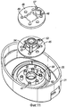
фиг.11 - разобранный вид в перспективе колпачка второго сменного элемента;11 is an exploded perspective view of a cap of a second interchangeable element;
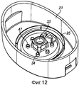
фиг.12 - вид, аналогичный фиг.11, показывающий собранный колпачок;12 is a view similar to FIG. 11 showing the assembled cap;
фиг.13 - вид в сечении клапана сброса давления второго примера;13 is a sectional view of a pressure relief valve of the second example;
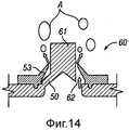
фиг.14 - вид, аналогичный фиг.13, показывающий клапан сброса давления в открытом виде, чтобы позволить поток воздуха;FIG. 14 is a view similar to FIG. 13 showing an open pressure relief valve to allow air flow;
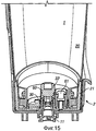
фиг.15 - вид, аналогичный фиг.4, показывающий третий сменный элемент на устройстве выдачи;Fig. 15 is a view similar to Fig. 4, showing a third interchangeable element on the dispenser;
фиг.16 - вид, аналогичный фиг.5, колпачка третьего сменного элемента;Fig.16 is a view similar to Fig.5, the cap of the third replaceable element;
фиг.17 - вид, аналогичный фиг.6, показывающий колпачок собранного третьего сменного элемента; иFig.17 is a view similar to Fig.6, showing the cap of the assembled third interchangeable element; and
фиг.18 - вид, аналогичный фиг.7, третьего сменного элемента.Fig. 18 is a view similar to Fig. 7 of the third interchangeable element.
Устройство выдачи является устройством выдачи, оставляющим руки свободными, которое, в общем, подходит для бытового пользования. Устройство выдачи главным образом предназначено для выдачи жидкого мыла, но также может быть использовано для выдачи другой жидкости или полужидких продуктов (в идеале с большей вязкостью, чем у воды), таких как крем для рук, лосьон для тела, увлажнитель, крем для лица, шампунь, гель для душа, пенящееся моющее средство, крем для бритья, жидкость для умывания, зубная паста, крем от угревой сыпи, средство для чистки поверхности или дезинфицирующее средство, например, спиртовой гель.A dispensing device is a dispensing device leaving hands free, which is generally suitable for domestic use. The dispenser is mainly intended for dispensing liquid soap, but can also be used to dispense other liquids or semi-liquid products (ideally with a higher viscosity than water), such as hand cream, body lotion, moisturizer, face cream, shampoo, shower gel, foaming detergent, shaving cream, washing liquid, toothpaste, acne cream, surface cleaner or disinfectant, such as alcohol gel.
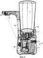
Устройство выдачи содержит две основные части, а именно сменный элемент 1 и блок 2 основания. Сменный элемент 1 обеспечивает емкость для выдаваемой жидкости и установлен в блок 2 основания, расположенный ниже.The issuing device contains two main parts, namely a
Основание имеет границу 3, в которую жидкость выдается из сменного элемента. Граница 3 сообщается по текучей среде с трубкой 4 выдачи. Насос 5 выполнен с возможностью выборочно нагнетать отмеренную дозу жидкости по трубке 4 выдачи и из головки 6 выдачи.The base has a boundary of 3, into which liquid is discharged from the replaceable element. Boundary 3 is in fluid communication with delivery pipe 4. The
Основание имеет инфракрасный передатчик 7A, который излучает инфракрасный луч через окно 8 в приемник 7B, чтобы распознать присутствие руки пользователя вблизи устройства выдачи. Схема управления реагирует на сигнал с датчика приближения, чтобы привести в действие насос. Показанный датчик является датчиком прерывания луча, но также может являться датчиком отражения. Хотя показан инфракрасный датчик, любой известный датчик приближения, такой как емкостной датчик, может быть использован. Устройство может быть с питанием от сети или с питанием от батареи. Как вариант, оно может являться устройством с управляемым вручную насосом, в котором пользователь толкает рычаг, чтобы сместить продукт.The base has an
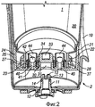
Граница между сменным элементом 1 и блоком 2 основания будет сейчас описана более подробно со ссылкой на фиг.2-10.The boundary between the
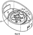
Блок 2 основания содержит кожух 10, который образует чашеобразный корпус, окружающий значительную часть сменного элемента, чтобы защищать и поддерживать его. Втулка 11 выступает через основание кожуха 10 и уплотнена к кожуху 10 уплотнительным кольцом 12. Втулка имеет множество зубцов 13 на ее верхней поверхности. Второе уплотнительное кольцо 14 окружает втулку 11 под зубцами 13.The
Сменный элемент 1 содержит флакон 20, к которому прикреплен колпачок 21. Флакон 20 имеет горлышко 22, которое насажено на и уплотнено кольцевым фланцем 23 внутри колпачка 21. Колпачок 21 имеет отходящую вверх юбку 24 (в перевернутом положении, показанном на чертежах), которая образует внешнюю поверхность колпачка. Перемещаясь внутри относительно юбки 24, следующим элементом колпачка является внешняя кольцевая стенка 25, которая в общем соосна с юбкой 24.The
Это подробно показано на фиг.5-10.This is shown in detail in FIGS. 5-10.
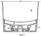
Внешняя кольцевая стенка 25 состоит из пары удерживающих элементов 26 и пары опорных элементов 27, которые чередуются друг с другом и каждый продолжается приблизительно на четверть круга, как показано на фиг.5, 6, 8 и 10. Сечение опорных элементов 27 показано на фиг.2. Эти элементы проходят прямо вверх от нижней стенки колпачка, имеют параллельные стороны и наклонную верхнюю поверхность 28. Сечение удерживающих элементов 26 показано на фиг.7 и 9. В отличие от опорных элементов 27, они не прикреплены к стенке колпачка. Взамен они прикреплены на другом конце к опорным элементам 27 предохранительными элементами 29, как лучшим образом показано на фиг.6 и 8. Удерживающие элементы 26 имеют параллельные стороны и имеют наклонную верхнюю поверхность 35, как показано на фиг.7 и 9.The outer
Как показано на фиг.7 и 9, горлышко 22 флакона имеет наклонную внешнюю поверхность 36, которая дополняет наклонные поверхности 28 и 35 кольцевой стенки 25. За наклонной внешней поверхностью 36 находится выступ 37, который обращен к основному корпусу флакона 20. Эта наклонная внешняя поверхность 36 и выступ 37 имеются только вблизи удерживающих элементов 26 и отсутствуют вблизи опорных элементов 27. Смежно с опорными элементами 27 горлышко 22 имеет параллельные стенки, как показано на фиг.2.As shown in FIGS. 7 and 9, the neck of the
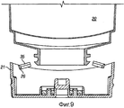
Для того чтобы вставить флакон 20 в колпачок 21, флакон 20 толкается вниз, причем его горлышко насаживается на кольцевой фланец 23. Наклонная внешняя поверхность 36 флакона взаимодействует с наклонными поверхностями 28, 35, чтобы сместить удерживающие элементы 26 радиально наружу до тех пор, пока выступ 37 не защелкнется на место за удерживающими элементами 26, как показано на фиг.7. Когда флакон 20 снимается с колпачка 21, выступы 37 упираются в удерживающие элементы 26, таким образом, разрушая предохранительные элементы 29 так, чтобы удерживающие элементы 26 отделились от колпачка 21, как показано на фиг.9 и 10. Как только это произошло, больше невозможно удерживать колпачок на флаконе, таким образом, предотвращая повторное использование сменного элемента 1.In order to insert the
Отметим, что нет необходимости в полном отделении обоих удерживающих элементов 26 от крышки. Возможно, что только один из них отделится, или что один или оба просто сместятся в положение, в котором они не могут больше зацепляться с горлышком флакона.Note that it is not necessary to completely separate both holding
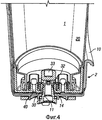
Возвращаясь теперь к фиг.2-4, выпускное отверстие для жидкости и связанный клапан сейчас будут описаны.Returning now to FIGS. 2-4, a fluid outlet and associated valve will now be described.
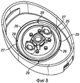
Выпускное отверстие для жидкости из резервуара обеспечено кольцевой стенкой 30, окружающей центральное отверстие 31. Наверху кольцевой стенки 30 находится наклонная поверхность 32 (см. фиг.4), которая обеспечивает седло клапана для элемента 33 клапана выпускного отверстия. Это показано в виде U-образного чашевидного элемента, но в равной степени может являться сплошным элементом или полым шарообразным элементом. Элемент 33 клапана выпускного отверстия отклонен в его закрытое положение множеством отклоняющих элементов 34.The fluid outlet from the reservoir is provided with an
Они прикреплены на их верхнем конце к верхней части элемента 33 клапана и прикреплены на их нижнем конце к месту радиально наружу от кольцевой стенки 30 и ниже верхней части кольцевой стенки 30. Они предпочтительно выполнены заодно с элементом 33 клапана.They are attached at their upper end to the upper part of the
Как показано на фиг.2-4, когда сменный элемент 1 опускается в блок 2 основания, втулка 11 зацепляется с нижней поверхностью элемента 33 клапана, как показано на фиг.3. Дальнейшее перемещение вниз сменного элемента вызывает подъем элемента 33 клапана с его седла и также приводит уплотнительное кольцо 14 в уплотняющее зацепление с кольцевой стенкой 30. Элемент 33 клапана поднимается в положение, показанное на фиг.4. В этом положении жидкость в флаконе 20 может течь вокруг отклоняющего элемента 34 и входит во втулку через зубцы 13, и таким образом протекая в блок 2 основания. Вытекание жидкости между втулкой 11 и кольцевой стенкой 30 предотвращается уплотнительным кольцом 14. Эта конструкция имеет простой и не создающий беспорядка для потребителя способ вставки сменного элемента независимо от уровня заполнения сменного элемента.As shown in FIGS. 2-4, when the
Для того чтобы удалить сменный элемент, потребитель вынимает его из основания, после чего отклоняющие элементы 34 вызывают возвращение элемента 33 клапана на седло 32. Во время этого перемещения уплотнение между втулкой 11 и кольцевой стенкой 30 обеспечивается уплотнительным кольцом 14. Использованный сменный элемент затем заменяется новым, следуя вышеприведенной схеме.In order to remove the replaceable element, the consumer takes it out of the base, after which the deflecting
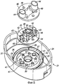
Колпачок снабжен парой клапанов 40 сброса давления. Каждый образован кольцевым выступом 41, выполненным заодно с колпачком 21. Элемент 42 клапана сброса давления опирается на верхнюю часть кольцевого выступа 41 и отклонен на место парой отклоняющих элементов 43 (как показано, например, на фиг.5). Отклоняющая сила такова, что при обычных условиях элемент 42 клапана сброса давления образует герметичное уплотнение на выступе 41. Однако когда давление внутри флакона 20 опускается ниже некоторого уровня, разность давлений на элементе 42 клапана сброса давления достаточна, чтобы преодолеть силу, прикладываемую отклоняющими элементами 43, и впустить воздух внутрь флакона 20. Это снижает разность давлений, таким образом, восстанавливая герметичное уплотнение без утечки текучей среды.The cap is provided with a pair of
Каждый клапан 40 сброса давления окружен кольцевым изолятором 44, который продолжается вдоль оси до уровня выше верхней кольцевой стенки 30 вдоль оси. Таким образом, когда элемент 33 клапана открыт, любой воздух, поступающий в клапан 40 сброса давления, не будет увлекаться истекающим потоком жидкости. На практике это означает, что клапан сброса давления может быть помещен ближе к выпускному отверстию, таким образом, приводя к более компактному колпачку. Хотя два клапана сброса давления показаны, один клапан или более двух клапанов могут быть обеспечены при необходимости.Each
Способ, которым собран колпачок, показан на фиг.5 и 6.The method by which the cap is assembled is shown in FIGS. 5 and 6.
Узел представляет собой трехчастную конструкцию, состоящую из колпачка 21, тарелки 45 клапана и крепежной пластины 46. Колпачок имеет некоторое количество литых элементов, включающих в себя кольцевой фланец 23, кольцевую стенку 25 и кольцевые выступы 41. Кроме того, колпачок 21 имеет множество крепежных стоек 47.The assembly is a three-part construction consisting of a
Тарелка 45 клапана является эластомерным материалом и выполнена заодно с элементом 33 клапана, отклоняющими элементами 34, элементом 42 клапана сброса давления и отклоняющими элементами 43. Тарелка клапана имеет множество установочных отверстий 48, которые соответствуют крепежным стойкам 47.The
Крепежная пластина 46 выполнена из жесткого пластика и выполнена заодно с кольцевым изолятором 44. Как и тарелка клапана 45, крепежная пластина 46 также снабжена множеством установочных отверстий 49, которые соответствуют крепежным стойкам 47.The mounting
Для сборки колпачка три компонента помещаются друг над другом, как показано на фиг.6, причем крепежные стойки входят в установочные отверстия, чтобы гарантировать, что компоненты выровнены правильно. Нагревание или адгезив затем прикладывается к верхней части крепежных стоек 47, чтобы прикрепить крепежные стойки к крепежной пластине 46. Эластомерная тарелка 45 клапана, таким образом, помещена между колпачком 21 и крепежной пластиной 46, которая удерживает элементы 33 и 42 клапана на месте.To assemble the cap, three components are placed one above the other, as shown in FIG. 6, with the mounting posts entering the mounting holes to ensure that the components are aligned correctly. Heat or adhesive is then applied to the top of the mounting
Второй пример колпачка для сменного элемента сейчас будет описан со ссылкой на фиг.11-14.A second example of a cap for an interchangeable member will now be described with reference to FIGS. 11-14.
Конструкция элемента 33 клапана выпускного отверстия во втором примере, по существу, такая же, как в первом примере, и не будет описываться снова в отношении второго примера.The design of the
Как можно видеть с фиг.11, колпачок 21 отлит заодно с некоторым количеством элементов, такими как кольцевая стенка 25 и 30 и коническая часть 50 клапана сброса давления, которая будет описана ниже. Упругий край 53 (описанный более подробно ниже) для клапана сброса давления обеспечен отлитым заодно с тарелкой 45 клапана. Крепежная пластина 46 также снабжена экраном 57 для клапана сброса давления. Он эквивалентен изолятору 44 на фиг.2, но только продолжается вокруг стороны клапана сброса давления, обращенной к элементу 33 клапана выпускного отверстия. Изолятор 44 и экран 57 могут использоваться взаимозаменяемо в двух примерах.As can be seen from FIG. 11, the
Узел колпачка собирается так же, как в первом примере.The cap assembly is assembled in the same way as in the first example.
Клапан 60 сброса давления показан на фиг.13 и 14.The
Клапан имеет коническую часть 50, которая является составной частью колпачка 21, как упомянуто выше. Наверху конической части 50 расположена цилиндрическая стойка 61. Упругий край 53 фактически является полым удлинением в виде усеченного конуса тарелки 52 клапана из упругого материала, который продолжается вдоль конической части 50, от которой он слегка расходится и плотно установлен на стойку 61. По меньшей мере, одно впускное отверстие 62 для воздуха (также показанное на фиг.11) проходит через стенку конической части 50 и, как правило, закрыто упругим краем 53, как показано на фиг.11. Когда давление в флаконе 20 падает по мере того, как жидкость выпускается, разности давлений на упругом крае 53 в конечном счете будет достаточно, чтобы сместить край 53 на достаточную величину, чтобы впустить воздух A внутрь флакона 20, как показано стрелками на фиг.8. Отметим, что величина, на которую упругий край 53 поднялся с конического элемента 50, была преувеличена на фиг.8 и что на практике она будет почти незаметна.The valve has a
Взамен уплотнения по стойке упругий край 53 может уплотнять по конической части 50. В этом случае край не будет отходить от конической части, как показано. Взамен он фактически будет иметь угол наклона меньше, чем угол конической части 50, для того чтобы естественно опираться на коническую часть.Instead of sealing on the strut, the
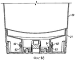
Пример третьего сменного элемента сейчас будет описан со ссылкой на фиг.15-18. Он в большинстве отношений аналогичен первому примеру, и только существенные различия описаны здесь.An example of a third interchangeable element will now be described with reference to FIGS. It is in most respects similar to the first example, and only significant differences are described here.
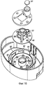
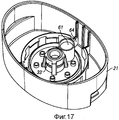
Как можно видеть на фиг.15, элемент 33' клапана выпускного отверстия оформлен иным образом. В этом случае присутствует участок 60 уменьшенного диаметра, который устанавливается внутри кольцевой стенки 30, когда клапан закрыт, чтобы способствовать уплотнению к кольцевой стенке.As can be seen in FIG. 15, the
Пара клапанов 40 сброса давления была заменена одним традиционным грибковым клапаном 61.A pair of
Удерживающие элементы 26 с их предохранительными элементами 29 были заменены множеством периодических выступов 62, которые, как показано на фиг.18, зацеплены с дополняющими выступами 63 на горлышке флакона 20. Прогиб горлышка флакона внутрь предотвращается фланцем 64. В положении с фиг.18 зацепление между выступами достаточно крепко, чтобы предотвратить удаление колпачка с флакона для всех практических целей. Это облегчается шпоночной конструкцией 64 на колпачке, как показано на фиг.16 и 17, которая зацеплена с дополняющим выступом на флаконе (не показан), чтобы предотвратить относительное вращение между колпачком 21 и флаконом 20.The retaining
Claims (15)
блок (2) основания с приводным механизмом для выдачи жидкости и
сменный элемент (1), вставляемый в блок (2) основания в перевернутом положении выпускным отверстием вниз для подачи жидкости в блок (2) основания, причем сменный элемент содержит кольцевую стенку (30), выступающую в сменный элемент (1) и образующую выпускное отверстие из сменного элемента (1), причем кольцевая стенка (30) выполнена с возможностью закрытия на ее наиболее внутреннем конце элементом (33) клапана, смещенным на кольцевую стенку (30), по меньшей мере, одним отклоняющим элементом (34), один или каждый из которых проходит в окружающую тарелку (45) клапана, которая прикреплена к колпачку (21) сменного элемента (1),
при этом блок (2) основания содержит полую втулку (11) и кольцевое уплотнение (12), окружающее верхнюю часть втулки и отстоящее от нее, за счет чего введение сменного элемента (1) в блок (2) основания вызывает введение втулки (11) в кольцевую стенку (30) и подъем элемента (33) клапана от кольцевой стенки (30), чтобы образовать канал потока из сменного элемента (1), через, по меньшей мере, один вырез, образованный в верхней части втулки и/или нижней части элемента (33) клапана, вниз полой втулки (11), и кольцевое уплотнение (14) для уплотнения между втулкой (11) и кольцевой стенкой (30).1. A device for dispensing a liquid containing
a block (2) of the base with a drive mechanism for dispensing liquid and
a replaceable element (1) inserted into the base unit (2) in an inverted position with the outlet downward for supplying liquid to the base unit (2), the replaceable element comprising an annular wall (30) protruding into the replaceable element (1) and forming an outlet from a replaceable element (1), wherein the annular wall (30) is configured to close at its innermost end a valve element (33) displaced onto the annular wall (30) by at least one deflecting element (34), one or each of which passes into the surrounding plate (45) a valve that is attached to the cap (21) of the replaceable element (1),
the block (2) of the base contains a hollow sleeve (11) and an annular seal (12) surrounding the upper part of the sleeve and spaced from it, due to which the introduction of a replaceable element (1) into the block (2) of the base causes the introduction of the sleeve (11) into the annular wall (30) and raising the valve element (33) from the annular wall (30) to form a flow channel from the replaceable element (1), through at least one cutout formed in the upper part of the sleeve and / or lower part the valve element (33), down the hollow sleeve (11), and the O-ring (14) for sealing between the sleeve (11) and the rings Eve wall (30).
отверстие (31) на одном конце, который при использовании является самым нижним концом, и
кольцевую стенку (30), размещенную в отверстии, выступающую в сменный элемент (1) и выполненную с возможностью закрытия на ее наиболее внутреннем конце элементом клапана (33), смещенным на кольцевую стенку (30), по меньшей мере, одним отклоняющим элементом (34), один или каждый из которых проходит в окружающую тарелку (45) клапана, которая прикреплена к колпачку (21) сменного элемента (1),
при этом, по меньшей мере, один отклоняющий элемент (34) соединен на одном конце с элементом клапана (33) и на другом конце с местом радиально наружу от и ниже наиболее внутреннего конца кольцевой стенки (30), причем один или каждый отклоняющий элемент (34) выполнен так, что, когда элемент (33) клапана поднят от кольцевой стенки (30), между элементом (33) клапана и кольцевой стенкой (30) имеется канал потока.8. A replaceable element for a fluid dispenser, the element comprising
a hole (31) at one end, which when used is the lowest end, and
an annular wall (30) located in the hole protruding into the interchangeable element (1) and configured to be closed at its innermost end by a valve element (33) displaced onto the annular wall (30) by at least one deflecting element (34 ), one or each of which passes into the surrounding plate (45) of the valve, which is attached to the cap (21) of the replaceable element (1),
wherein at least one deflecting element (34) is connected at one end to the valve element (33) and at the other end with a place radially outward from and below the innermost end of the annular wall (30), one or each deflecting element ( 34) is configured such that when the valve member (33) is raised from the annular wall (30), there is a flow channel between the valve member (33) and the annular wall (30).
Applications Claiming Priority (3)
| Application Number | Priority Date | Filing Date | Title |
|---|---|---|---|
| GBGB0820981.9A GB0820981D0 (en) | 2008-11-17 | 2008-11-17 | Dispenser and refill unit |
| GB0820981.9 | 2008-11-17 | ||
| PCT/GB2009/002682 WO2010055314A1 (en) | 2008-11-17 | 2009-11-17 | Dispenser and refill unit |
Publications (2)
| Publication Number | Publication Date |
|---|---|
| RU2011124521A RU2011124521A (en) | 2012-12-27 |
| RU2531725C2 true RU2531725C2 (en) | 2014-10-27 |
Family
ID=40194738
Family Applications (1)
| Application Number | Title | Priority Date | Filing Date |
|---|---|---|---|
| RU2011124521/12A RU2531725C2 (en) | 2008-11-17 | 2009-11-17 | Output device and replaceable element |
Country Status (15)
| Country | Link |
|---|---|
| US (2) | US8662356B2 (en) |
| EP (2) | EP3431439A1 (en) |
| JP (1) | JP5425223B2 (en) |
| KR (1) | KR101601190B1 (en) |
| CN (1) | CN102216200B (en) |
| AU (1) | AU2009315391B2 (en) |
| BR (1) | BRPI0921551B1 (en) |
| CA (1) | CA2743259A1 (en) |
| GB (1) | GB0820981D0 (en) |
| HK (1) | HK1163045A1 (en) |
| MX (1) | MX2011005086A (en) |
| MY (1) | MY156557A (en) |
| RU (1) | RU2531725C2 (en) |
| WO (1) | WO2010055314A1 (en) |
| ZA (1) | ZA201103449B (en) |
Families Citing this family (50)
| Publication number | Priority date | Publication date | Assignee | Title |
|---|---|---|---|---|
| GB0820984D0 (en) * | 2008-11-17 | 2008-12-24 | Reckitt & Colman Overseas | A bottle with a tamper-proof cap |
| GB0820981D0 (en) * | 2008-11-17 | 2008-12-24 | Reckitt & Colman Overseas | Dispenser and refill unit |
| BR112012011566A2 (en) * | 2009-10-09 | 2016-06-28 | Py Daniel C | co-molded locking device, one-way valves, variable volume storage chamber and related method |
| GB201007238D0 (en) * | 2010-04-30 | 2010-06-16 | Reckitt & Colman Overseas | A liquid delivery system |
| US20120111884A1 (en) * | 2010-10-21 | 2012-05-10 | Chun Kwong Choi | Automatic soap dispenser with notification function |
| GB201018005D0 (en) * | 2010-10-26 | 2010-12-08 | Reckitt Benckiser Inc | Dispenser for a foaming liquid composition |
| GB2484935A (en) | 2010-10-26 | 2012-05-02 | Reckitt Benckiser Llc | Container with frangible device interface |
| GB201020841D0 (en) | 2010-12-09 | 2011-01-19 | Reckitt & Colman Overseas | Dispenser for a foaming liquid composition with improved foam recovery feature |
| GB201104525D0 (en) | 2011-03-17 | 2011-05-04 | Reckitt & Colman Overseas | Dispenser and refill unit |
| US8616420B2 (en) | 2011-12-15 | 2013-12-31 | The Dial Corporation | Bottle closure with breakaway skirt for non-refillable bottles |
| US9265383B2 (en) | 2012-02-08 | 2016-02-23 | Simplehuman, Llc | Liquid dispensing units |
| GB201202578D0 (en) | 2012-02-15 | 2012-03-28 | Reckitt Benckiser Llc | Dispenser and refill unit and dispensing methods |
| AU2013204782A1 (en) * | 2012-02-24 | 2013-09-12 | The Coca-Cola Company | Mechanical dispensing system |
| US8851335B2 (en) * | 2012-04-17 | 2014-10-07 | Gojo Industries, Inc. | Water-driven dispensing systems employing concentrated product |
| US9038862B2 (en) * | 2013-01-23 | 2015-05-26 | Gojo Industries, Inc. | Pumps with container vents |
| US9271613B2 (en) | 2013-02-15 | 2016-03-01 | Delta Faucet Company | Electronic soap dispenser |
| US9648992B2 (en) * | 2013-12-19 | 2017-05-16 | Gojo Industries, Inc. | Pumps with vents to vent inverted containers and refill units having non-collapsing containers |
| US10433372B2 (en) | 2013-12-20 | 2019-10-01 | Toaster Labs, Inc. | Portable fluid warming device |
| US10144032B2 (en) | 2013-12-20 | 2018-12-04 | Toaster Labs, Inc. | Inductively heatable fluid reservoir |
| US10098510B2 (en) | 2013-12-20 | 2018-10-16 | Toaster Loabs, Inc. | Pneumatically driven fluid dispenser |
| US9974416B2 (en) | 2013-12-20 | 2018-05-22 | Toaster Labs, Inc. | Automatic heated fluid dispenser |
| US9801505B2 (en) | 2013-12-20 | 2017-10-31 | Toaster Labs, Inc. | Automatic fluid dispenser |
| US10189038B2 (en) | 2013-12-20 | 2019-01-29 | Toaster Labs, Inc. | Inductively heatable fluid reservoir for various fluid types |
| EP3094224A1 (en) | 2014-01-15 | 2016-11-23 | Gojo Industries, Inc. | Pumps with angled outlets, refill units and dispensers having angled outlets |
| AU2015218741B2 (en) | 2014-02-24 | 2019-07-11 | Gojo Industries, Inc. | Vented non-collapsing containers, refillable refill containers, dispensers and refill units |
| GB201404950D0 (en) * | 2014-03-19 | 2014-04-30 | Reckitt Benckiser Brands Ltd | Dispensing device |
| AU2014401829A1 (en) * | 2014-07-25 | 2017-02-09 | Abb Schweiz Ag | Refill-container for replenishing and/or reconditioning an insulation fluid contained in an insulation space of an electrical apparatus |
| US9596963B2 (en) | 2014-07-30 | 2017-03-21 | Gojo Industries, Inc. | Vented refill units and dispensers having vented refill units |
| US10517441B2 (en) * | 2014-08-27 | 2019-12-31 | Gojo Industries, Inc. | Energy harvesting for dispensing system |
| MY186715A (en) | 2014-10-02 | 2021-08-12 | Unilever Plc | Liquid dispenser with framed refill receiving bay |
| US9884336B2 (en) * | 2014-10-10 | 2018-02-06 | The Procter & Gamble Company | Multifunctional dispensing device for dispensing fluid compositions |
| GB2535239A (en) | 2015-02-13 | 2016-08-17 | Nerudia Ltd | System and apparatus |
| GB2535982A (en) | 2015-02-13 | 2016-09-07 | Nerudia Ltd | System and apparatus |
| US10076216B2 (en) * | 2015-02-25 | 2018-09-18 | Simplehuman, Llc | Foaming soap dispensers |
| USD773848S1 (en) | 2015-03-06 | 2016-12-13 | Simplehuman, Llc | Liquid dispenser cartridge |
| CA2922625A1 (en) | 2015-03-06 | 2016-09-06 | Simplehuman, Llc | Foaming soap dispensers |
| GB201517754D0 (en) * | 2015-10-07 | 2015-11-18 | Rieke Packaging Systems Ltd | Liquid dosing devices |
| GB2537471B (en) * | 2016-02-25 | 2017-09-06 | Packaging Innovation Ltd | A fluid coupling |
| CN109310199B (en) * | 2016-06-08 | 2020-10-09 | 瑞克·索利 | Exercise hydration apparatus |
| NL2017109B1 (en) | 2016-07-05 | 2018-01-12 | Heineken Supply Chain Bv | Beverage dispensing assembly and beverage container |
| ES2943244T3 (en) | 2016-10-28 | 2023-06-12 | Rb Health Us Llc | feminine hygiene products |
| ES2857923T3 (en) | 2017-03-17 | 2021-09-29 | Simplehuman Llc | Soap pump |
| NL2018956B1 (en) | 2017-05-19 | 2018-11-28 | Heineken Supply Chain Bv | Beverage dispensing assembly and beverage container |
| NL2018955B1 (en) * | 2017-05-19 | 2018-11-28 | Heineken Supply Chain Bv | Beverage dispensing assembly and beverage container |
| CA3076847A1 (en) * | 2017-10-09 | 2019-04-18 | Pathspot Technologies Inc. | Systems and methods for detection of contaminants on surfaces |
| USD962672S1 (en) | 2020-08-26 | 2022-09-06 | Simplehuman, Llc | Dispenser |
| USD967650S1 (en) | 2020-10-26 | 2022-10-25 | Simplehuman, Llc | Liquid dispenser |
| US11918156B2 (en) | 2021-02-05 | 2024-03-05 | Simplehuman, Llc | Push-pump for dispensing soap or other liquids |
| US11759060B2 (en) | 2021-02-08 | 2023-09-19 | Simplehuman, Llc | Portable consumer liquid pump |
| US11641985B2 (en) * | 2021-04-13 | 2023-05-09 | Alo New York Llc | Modular fluid dispensing system |
Citations (1)
| Publication number | Priority date | Publication date | Assignee | Title |
|---|---|---|---|---|
| US5556005A (en) * | 1995-01-09 | 1996-09-17 | Sprintvest Corporation Nv | Collapsible soap dispenser |
Family Cites Families (15)
| Publication number | Priority date | Publication date | Assignee | Title |
|---|---|---|---|---|
| FR2198559A5 (en) * | 1972-08-30 | 1974-03-29 | Seppic Sa | Removable liquid-soap dispenser - with polypropylene supply container |
| US4964544A (en) * | 1988-08-16 | 1990-10-23 | Bobrick Washroom Equipment, Inc. | Push up dispenser with capsule valve |
| US5031676A (en) * | 1988-09-30 | 1991-07-16 | Liqui-Box Corporation | Decap dispensing system for water cooler bottles |
| US5273083A (en) * | 1991-10-07 | 1993-12-28 | Ebtech, Inc. | Bottle cap and valve assembly for a bottled water station |
| US5232125A (en) * | 1991-10-08 | 1993-08-03 | Portola Packaging, Inc. | Non-spill bottle cap used with water dispensers |
| US5839614A (en) * | 1991-12-06 | 1998-11-24 | Aptar Group, Inc. | Dispensing package |
| CN2140353Y (en) * | 1992-12-29 | 1993-08-18 | 江鑫 | Valve implement of infrared detergent feeder |
| US6269837B1 (en) * | 1998-11-09 | 2001-08-07 | The Procter & Gamble Company | Rechargeable dispensing system |
| US6276565B1 (en) * | 1999-05-11 | 2001-08-21 | Arichell Technologies, Inc. | Gas-driven liquid dispenser employing separate pressurized-gas source |
| WO2008119158A1 (en) * | 2007-03-30 | 2008-10-09 | Toronto Rehabilitation Institute | Hand hygiene compliance system |
| US8237558B2 (en) * | 2007-03-30 | 2012-08-07 | University Health Network | Hand hygiene compliance system |
| GB2449469B (en) * | 2007-05-23 | 2011-11-23 | Brightwell Dispensers Ltd | Coupling |
| GB0820984D0 (en) * | 2008-11-17 | 2008-12-24 | Reckitt & Colman Overseas | A bottle with a tamper-proof cap |
| GB0820981D0 (en) * | 2008-11-17 | 2008-12-24 | Reckitt & Colman Overseas | Dispenser and refill unit |
| US8245877B2 (en) * | 2009-07-22 | 2012-08-21 | Gotohti.Com Inc. | Dispenser with palm reader |
-
2008
- 2008-11-17 GB GBGB0820981.9A patent/GB0820981D0/en not_active Ceased
-
2009
- 2009-11-17 EP EP18182502.7A patent/EP3431439A1/en not_active Ceased
- 2009-11-17 KR KR1020117012401A patent/KR101601190B1/en active IP Right Grant
- 2009-11-17 EP EP09760264.3A patent/EP2365933B1/en active Active
- 2009-11-17 MY MYPI2011002151A patent/MY156557A/en unknown
- 2009-11-17 RU RU2011124521/12A patent/RU2531725C2/en active
- 2009-11-17 BR BRPI0921551-4A patent/BRPI0921551B1/en active IP Right Grant
- 2009-11-17 AU AU2009315391A patent/AU2009315391B2/en active Active
- 2009-11-17 WO PCT/GB2009/002682 patent/WO2010055314A1/en active Application Filing
- 2009-11-17 CN CN200980145568XA patent/CN102216200B/en active Active
- 2009-11-17 MX MX2011005086A patent/MX2011005086A/en active IP Right Grant
- 2009-11-17 JP JP2011543808A patent/JP5425223B2/en active Active
- 2009-11-17 US US13/129,164 patent/US8662356B2/en active Active
- 2009-11-17 CA CA2743259A patent/CA2743259A1/en not_active Abandoned
-
2011
- 2011-05-11 ZA ZA2011/03449A patent/ZA201103449B/en unknown
-
2012
- 2012-04-12 HK HK12103573.5A patent/HK1163045A1/en unknown
-
2013
- 2013-11-22 US US14/087,433 patent/US8998036B2/en active Active
Patent Citations (1)
| Publication number | Priority date | Publication date | Assignee | Title |
|---|---|---|---|---|
| US5556005A (en) * | 1995-01-09 | 1996-09-17 | Sprintvest Corporation Nv | Collapsible soap dispenser |
Also Published As
| Publication number | Publication date |
|---|---|
| US20140084021A1 (en) | 2014-03-27 |
| US8662356B2 (en) | 2014-03-04 |
| BRPI0921551B1 (en) | 2019-06-18 |
| KR20110086127A (en) | 2011-07-27 |
| RU2011124521A (en) | 2012-12-27 |
| WO2010055314A1 (en) | 2010-05-20 |
| MY156557A (en) | 2016-02-26 |
| CN102216200B (en) | 2013-03-27 |
| US8998036B2 (en) | 2015-04-07 |
| AU2009315391A1 (en) | 2010-05-20 |
| GB0820981D0 (en) | 2008-12-24 |
| US20120097711A1 (en) | 2012-04-26 |
| EP2365933A1 (en) | 2011-09-21 |
| CN102216200A (en) | 2011-10-12 |
| MX2011005086A (en) | 2011-07-29 |
| EP3431439A1 (en) | 2019-01-23 |
| CA2743259A1 (en) | 2010-05-20 |
| JP5425223B2 (en) | 2014-02-26 |
| EP2365933B1 (en) | 2018-08-22 |
| KR101601190B1 (en) | 2016-03-08 |
| JP2012508676A (en) | 2012-04-12 |
| HK1163045A1 (en) | 2012-09-07 |
| AU2009315391B2 (en) | 2013-06-13 |
| BRPI0921551A2 (en) | 2016-03-08 |
| ZA201103449B (en) | 2012-07-25 |
Similar Documents
| Publication | Publication Date | Title |
|---|---|---|
| RU2531725C2 (en) | Output device and replaceable element | |
| RU2494941C2 (en) | Flask with tamper-evident cap | |
| RU2504506C2 (en) | Pressure-relief valve | |
| EP3119528B1 (en) | Dispensing device | |
| WO2012123763A2 (en) | Dispenser and refill unit |
Legal Events
| Date | Code | Title | Description |
|---|---|---|---|
| PC41 | Official registration of the transfer of exclusive right |
Effective date: 20200204 |