RU2531712C2 - Blade of gas turbine with cooled tip of peripheral part of blade - Google Patents
Blade of gas turbine with cooled tip of peripheral part of blade Download PDFInfo
- Publication number
- RU2531712C2 RU2531712C2 RU2011141997/06A RU2011141997A RU2531712C2 RU 2531712 C2 RU2531712 C2 RU 2531712C2 RU 2011141997/06 A RU2011141997/06 A RU 2011141997/06A RU 2011141997 A RU2011141997 A RU 2011141997A RU 2531712 C2 RU2531712 C2 RU 2531712C2
- Authority
- RU
- Russia
- Prior art keywords
- blade
- cooling
- cooling holes
- angle
- channel
- Prior art date
Links
Images


Classifications
-
- F—MECHANICAL ENGINEERING; LIGHTING; HEATING; WEAPONS; BLASTING
- F01—MACHINES OR ENGINES IN GENERAL; ENGINE PLANTS IN GENERAL; STEAM ENGINES
- F01D—NON-POSITIVE DISPLACEMENT MACHINES OR ENGINES, e.g. STEAM TURBINES
- F01D5/00—Blades; Blade-carrying members; Heating, heat-insulating, cooling or antivibration means on the blades or the members
- F01D5/12—Blades
- F01D5/14—Form or construction
- F01D5/20—Specially-shaped blade tips to seal space between tips and stator
-
- F—MECHANICAL ENGINEERING; LIGHTING; HEATING; WEAPONS; BLASTING
- F05—INDEXING SCHEMES RELATING TO ENGINES OR PUMPS IN VARIOUS SUBCLASSES OF CLASSES F01-F04
- F05D—INDEXING SCHEME FOR ASPECTS RELATING TO NON-POSITIVE-DISPLACEMENT MACHINES OR ENGINES, GAS-TURBINES OR JET-PROPULSION PLANTS
- F05D2240/00—Components
- F05D2240/20—Rotors
- F05D2240/30—Characteristics of rotor blades, i.e. of any element transforming dynamic fluid energy to or from rotational energy and being attached to a rotor
- F05D2240/307—Characteristics of rotor blades, i.e. of any element transforming dynamic fluid energy to or from rotational energy and being attached to a rotor related to the tip of a rotor blade
-
- F—MECHANICAL ENGINEERING; LIGHTING; HEATING; WEAPONS; BLASTING
- F05—INDEXING SCHEMES RELATING TO ENGINES OR PUMPS IN VARIOUS SUBCLASSES OF CLASSES F01-F04
- F05D—INDEXING SCHEME FOR ASPECTS RELATING TO NON-POSITIVE-DISPLACEMENT MACHINES OR ENGINES, GAS-TURBINES OR JET-PROPULSION PLANTS
- F05D2250/00—Geometry
- F05D2250/20—Three-dimensional
- F05D2250/23—Three-dimensional prismatic
- F05D2250/231—Three-dimensional prismatic cylindrical
-
- F—MECHANICAL ENGINEERING; LIGHTING; HEATING; WEAPONS; BLASTING
- F05—INDEXING SCHEMES RELATING TO ENGINES OR PUMPS IN VARIOUS SUBCLASSES OF CLASSES F01-F04
- F05D—INDEXING SCHEME FOR ASPECTS RELATING TO NON-POSITIVE-DISPLACEMENT MACHINES OR ENGINES, GAS-TURBINES OR JET-PROPULSION PLANTS
- F05D2250/00—Geometry
- F05D2250/20—Three-dimensional
- F05D2250/23—Three-dimensional prismatic
- F05D2250/232—Three-dimensional prismatic conical
-
- F—MECHANICAL ENGINEERING; LIGHTING; HEATING; WEAPONS; BLASTING
- F05—INDEXING SCHEMES RELATING TO ENGINES OR PUMPS IN VARIOUS SUBCLASSES OF CLASSES F01-F04
- F05D—INDEXING SCHEME FOR ASPECTS RELATING TO NON-POSITIVE-DISPLACEMENT MACHINES OR ENGINES, GAS-TURBINES OR JET-PROPULSION PLANTS
- F05D2260/00—Function
- F05D2260/20—Heat transfer, e.g. cooling
- F05D2260/202—Heat transfer, e.g. cooling by film cooling
Abstract
Description
Область техники, к которой относится изобретениеFIELD OF THE INVENTION
Настоящее изобретение относится к области технологии изготовления газовой турбины, в частности относится к охлаждаемой лопатке для газовой турбины.The present invention relates to the field of gas turbine manufacturing technology, in particular to a cooled blade for a gas turbine.
Уровень техникиState of the art
Эффективность газовых турбин зависит, по существу, от температуры горячего газа, который расширяется в турбине при выполнении работы. Для того чтобы была возможность повысить эффективность турбин, такие компоненты, как лопатки статора, лопатки ротора, сегменты, аккумулирующие тепло и т.д., должны быть изготовлены не только из особо устойчивых материалов, но также должны охлаждаться настолько эффективно, насколько это возможно, во время работы турбины. В известном уровне техники были разработаны различные способы для охлаждения лопаток, которые могут использоваться альтернативно или вместе. Одним из способов является прохождение охлаждающей среды, обычно сжатого охлажденного воздуха из компрессора газовой турбины, через внутреннюю часть лопаток в охлаждающих каналах, чтобы затем позволить ему выйти в горячий газовый канал через охлаждающие отверстия, расположенные распределенным образом. Охлаждающие каналы могут в этом случае проходить через внутреннюю часть лопатки более чем один раз в форме серпантина (см., например, документ WO-A1-2005/068783). Передача тепла между охлаждающей средой и стенками лопатки может быть в этом случае улучшена за счет использования подходящих элементов (турбулизаторов), чтобы образовать дополнительную турбулентность в потоке охлаждающей среды, или за счет использования принудительного охлаждения. В другом способе охлаждающая среда может выходить из внутренней части лопатки таким образом, что на поверхности лопатки образуется пленка из охлаждающей среды, и защищает лопатку (пленочное охлаждение).The efficiency of gas turbines depends essentially on the temperature of the hot gas, which expands in the turbine during work. In order to be able to increase the efficiency of turbines, components such as stator vanes, rotor vanes, heat storage segments, etc., must be made not only of highly resistant materials, but also must be cooled as efficiently as possible. during turbine operation. In the prior art, various methods have been developed for cooling the blades, which can be used alternatively or together. One way is to pass a cooling medium, usually compressed chilled air from a gas turbine compressor, through the interior of the blades in the cooling channels, to then allow it to exit into the hot gas channel through cooling holes arranged in a distributed manner. The cooling channels may then pass through the inside of the blade more than once in the form of a serpentine (see, for example, document WO-A1-2005 / 068783). The heat transfer between the cooling medium and the walls of the blade can in this case be improved by using suitable elements (turbulators) to form additional turbulence in the flow of the cooling medium, or by using forced cooling. In another method, the cooling medium may exit the inside of the blade so that a film of cooling medium forms on the surface of the blade and protects the blade (film cooling).
Особенно важно охлаждать периферическую часть (законцовку) лопатки. Законцовка лопатки является частью лопатки, которая располагается с наибольшим удалением от хвостовика лопатки, через которую подается охлаждающий воздух. Поэтому для ее охлаждения должно быть уделено особое внимание. Кроме того, охлаждение, которое является настолько однородным, насколько это возможно, должно быть достигнуто во всех рабочих состояниях, при этом потребление охлаждающей среды должно быть ограничено до необходимой степени, для того чтобы избежать неблагоприятного влияния на эффективность машины.It is especially important to cool the peripheral part (tip) of the scapula. The tip of the blade is part of the blade, which is located with the greatest distance from the shank of the blade, through which cooling air is supplied. Therefore, special attention must be paid to its cooling. In addition, cooling, which is as uniform as possible, must be achieved in all operating conditions, while the consumption of the cooling medium must be limited to the extent necessary in order to avoid adverse effects on machine performance.
Документ DE-A1-199 44 923 раскрывает сравнительно сложное решение для охлаждения периферической части лопатки.DE-A1-199 44 923 discloses a relatively complex solution for cooling the peripheral part of a blade.
Раскрытие изобретенияDisclosure of invention
То, что было описано выше, является целью изобретения. Поэтому задачей изобретения является обеспечение охлаждаемой лопатки для газовой турбины, которая характеризуется, в частности, лучшим охлаждением в области периферии лопатки.What has been described above is an object of the invention. It is therefore an object of the invention to provide a cooled blade for a gas turbine, which is characterized in particular by better cooling in the periphery of the blade.
Эта задача полностью достигается с помощью признаков независимого пункта 1 формулы изобретения. Главным аспектом изобретения является то, что первые охлаждающие отверстия для охлаждающей конвекции обеспечиваются на рабочей поверхности лопатки, а вторые охлаждающие отверстия для пленочного охлаждения обеспечиваются на поверхности разрежения лопатки, через законцовку лопатки в периферической части лопатки из охлаждающих каналов и распределяются по ширине лопатки. Комбинация конвекционного охлаждения на рабочей поверхности и пленочного охлаждения на стороне разрежения конца лопатки приводит в результате к особенно эффективному и стабильному охлаждению, при этом не оказывая какого-либо неблагоприятного влияния на эффективность машины.This task is fully achieved using the features of the
Согласно первому варианту осуществления изобретения первое и второе охлаждающие отверстия содержат, по меньшей мере, секции в форме цилиндрических каналов с заданным первым диаметром.According to a first embodiment of the invention, the first and second cooling holes comprise at least sections in the form of cylindrical channels with a predetermined first diameter.
В особенности первые охлаждающие отверстия имеют форму длинных цилиндрических каналов, которые проходят наклонно вверх и включают в себя первый угол между 25° и 35°, предпочтительно приблизительно 30° по отношению к внешней поверхности лопатки.In particular, the first cooling holes are in the form of long cylindrical channels that extend obliquely upward and include a first angle between 25 ° and 35 °, preferably approximately 30 °, with respect to the outer surface of the blade.
Согласно второму варианту осуществления изобретения первые охлаждающие отверстия открыты в окружающее лопатку пространство с веерообразной секцией канала.According to a second embodiment of the invention, the first cooling openings are open in the space surrounding the scapula with a fan-shaped section of the channel.
Согласно третьему варианту осуществления изобретения, те из первых охлаждающих отверстий, которые располагаются снаружи задней кромки лопатки, открыты в окружающее лопатку пространство с трехмерной симметрией веерообразной секции канала, посредством чего вышеуказанная веерообразная секция с трехмерной (3D) симметрией имеет первый угол отверстия, имеющий диапазон от 10° до 50° и предпочтительно составляющий около 24°, а второй угол отверстия перпендикулярен вышеуказанному первому углу отверстия, при этом вышеуказанный второй угол отверстая имеет диапазон от 5 до 25° и предпочтительно составляет около 12°.According to a third embodiment of the invention, those of the first cooling holes that are located outside the trailing edge of the blade are open into the space surrounding the blade with three-dimensional symmetry of the fan-shaped section of the channel, whereby the aforementioned fan-shaped section with three-dimensional (3D) symmetry has a first opening angle having a range from 10 ° to 50 ° and preferably about 24 °, and the second angle of the hole is perpendicular to the above first corner of the hole, while the above second angle is open the thaw has a range of 5 to 25 ° and is preferably about 12 °.
Согласно четвертому варианту осуществления изобретения те из первых охлаждающих отверстий, которые располагаются снаружи задней кромки лопатки, включают в себя второй угол между 15° и 45°, предпочтительно приблизительно 30°, по отношению к внешней поверхности лопатки.According to a fourth embodiment of the invention, those of the first cooling holes which are located outside the trailing edge of the blade include a second angle between 15 ° and 45 °, preferably approximately 30 °, with respect to the outer surface of the blade.
Согласно пятому варианту осуществления изобретения те из первых охлаждающих отверстий, которые располагаются на задней кромке лопатки, открыты в окружающее лопатку пространство с двухмерной (2D) симметрией веерообразной секции канала, посредством чего вышеуказанная веерообразная секция с двухмерной симметрией имеет третий угол отверстия, имеющий диапазон от 10° до 40° и предпочтительно составляющий около 20°.According to a fifth embodiment of the invention, those of the first cooling holes that are located at the trailing edge of the blade are open into the space surrounding the blade with two-dimensional (2D) symmetry of the fan-shaped section of the channel, whereby the aforementioned fan-shaped section with two-dimensional symmetry has a third opening angle having a range of 10 ° to 40 ° and preferably constituting about 20 °.
Согласно шестому варианту осуществления изобретения те из первых охлаждающих отверстий, которые располагаются на задней кромке лопатки, включают в себя третий угол между 5° и 45°, предпочтительно приблизительно 30° по отношению к внешней поверхности лопатки.According to a sixth embodiment, those of the first cooling holes that are located on the trailing edge of the blade include a third angle between 5 ° and 45 °, preferably approximately 30 °, with respect to the outer surface of the blade.
Согласно седьмому варианту осуществления изобретения те из первых охлаждающих отверстий, которые располагаются на задней кромке лопатки, имеют канал с заданной первой длиной, которая подразделяется на вышеуказанную веерообразную секцию с двухмерной симметрией и цилиндрическую секцию с заданной второй длиной, посредством чего соотношение вышеуказанной второй длины и вышеуказанной первой длины находится в диапазоне от 0,2 до 0,7 и предпочтительно составляет около 0,5.According to a seventh embodiment of the invention, those of the first cooling holes that are located at the trailing edge of the blade have a channel with a predetermined first length that is subdivided into the aforementioned fan-shaped section with two-dimensional symmetry and a cylindrical section with a predetermined second length, whereby the ratio of the above second length to the above the first length is in the range from 0.2 to 0.7, and is preferably about 0.5.
Согласно девятому варианту осуществления изобретения первые охлаждающие отверстия располагаются вдоль рабочей поверхности в виде ряда с заданной первой периодичностью и соотношением между вышеуказанной первой периодичностью и вышеуказанным первым диаметром, который находится в диапазоне от 3 до 8 и предпочтительно составляет около 6.According to a ninth embodiment of the invention, the first cooling holes are arranged along the working surface in a row with a predetermined first periodicity and a ratio between the above first periodicity and the above first diameter, which is in the range from 3 to 8 and preferably is about 6.
Согласно десятому варианту осуществления изобретения вторые охлаждающие отверстия проходят через законцовку лопатки в радиальном направлении, за счет чего вторые охлаждающие отверстия выполнены в форме длинных цилиндрических каналов, которые проходят наклонно вверх и включают в себя угол от 0° до 45°, предпочтительно приблизительно 30° по отношению к продольной оси лопатки.According to a tenth embodiment of the invention, the second cooling holes extend radially through the tip of the blade, whereby the second cooling holes are made in the form of long cylindrical channels that extend obliquely upward and include an angle from 0 ° to 45 °, preferably approximately 30 ° relative to the longitudinal axis of the scapula.
Согласно одиннадцатому варианту осуществления изобретения вторые охлаждающие отверстия располагаются вдоль поверхности разрежения лопатки в виде ряда с заданной второй периодичностью и соотношением между вышеуказанной второй периодичностью и вышеуказанным первым диаметром, который находится в диапазоне от 3 до 8 и предпочтительно составляет около 6.According to an eleventh embodiment of the invention, the second cooling holes are arranged along the rarefaction surface of the blade in the form of a row with a predetermined second periodicity and the ratio between the above second periodicity and the above first diameter, which is in the range from 3 to 8 and preferably is about 6.
Согласно другому варианту осуществления изобретения вышеуказанные первые охлаждающие отверстия выходят в окружающее лопатку пространство с заданной высотой ниже верхнего конца периферической части лопатки и соотношением между вышеуказанной высотой и вышеуказанным первым диаметром, который находится в диапазоне между 5 и 10 и предпочтительно составляет около 6,5.According to another embodiment of the invention, the aforementioned first cooling openings extend into the space surrounding the blade with a predetermined height below the upper end of the peripheral part of the blade and the ratio between the above height and the above first diameter, which is in the range between 5 and 10 and is preferably about 6.5.
Согласно другому варианту осуществления изобретения имеются пылевые отверстия, расположенные вдоль законцовки между вышеуказанными передней кромкой и задней кромкой, при этом вышеуказанные пылевые отверстия имеют второй диаметр, при этом соотношение между вышеуказанным вторым диаметром и вышеуказанным первым диаметром находится между 1, 2 и 4, 5.According to another embodiment of the invention, there are dust openings located along the tip between the aforementioned leading edge and trailing edge, the aforementioned dust openings having a second diameter, and the ratio between the aforementioned second diameter and the aforementioned first diameter is between 1, 2 and 4, 5.
Согласно другому варианту осуществления изобретения законцовка лопатки ограничена на ее краю на верхней поверхности с помощью периферического обода лопатки, а вторые охлаждающие отверстия открыты в наружную область внутри обода лопатки.According to another embodiment of the invention, the tip of the blade is bounded at its edge on the upper surface by the peripheral rim of the blade, and the second cooling holes are open to the outer region inside the blade rim.
Предпочтительно вышеуказанная лопатка имеет обод лопатки в периферической части лопатки, которая ограничена с помощью периферического барьера, имеющего заданную толщину, в соответствии с чем ширина между противолежащими барьерами изменяется с расстоянием вдоль линии хорды, так что t/W находится между 0,05 и 0,15 для к/к0 между 0 и 0,3, и t/W находится между 0,15 и 0,3 для к/к0 больше чем 0,3 и до 1,0, при этом к0 является общей длиной линии хорды.Preferably, the aforementioned blade has a blade rim in the peripheral part of the blade, which is limited by a peripheral barrier having a predetermined thickness, whereby the width between opposing barriers varies with the distance along the line of the chord, so that t / W is between 0.05 and 0, 15 for f / c 0 between 0 and 0.3, and t / W is between 0.15 and 0.3 for f / c 0 greater than 0.3 and up to 1.0, with k 0 being the total length of the line chords.
Кроме того, что касается геометрии периферической части лопатки, предпочтительными являются следующие соотношения:In addition, with regard to the geometry of the peripheral part of the scapula, the following ratios are preferred:
где D означает глубину обода на периферии лопатки, a W означает ширину согласно фиг.3а.where D is the depth of the rim at the periphery of the blade, and W is the width according to figa.
Краткое описание чертежейBrief Description of the Drawings
Изобретение будет объясняться более подробно в последующей части текста со ссылками на показательные варианты осуществления изобретения и в сочетании с прилагаемыми чертежами. Чертежи показывают только те элементы, которые необходимы для непосредственного понимания изобретения. Те же самые элементы обеспечиваются теми же самыми ссылочными символами на различных фигурах, в которых:The invention will be explained in more detail in the subsequent part of the text with reference to illustrative embodiments of the invention and in combination with the accompanying drawings. The drawings show only those elements that are necessary for a direct understanding of the invention. The same elements are provided with the same reference characters in various figures in which:
фиг.1 показывает поперечное сечение профиля через аэродинамическую секцию лопатки, которая подходит для применения изобретения;figure 1 shows a cross section of the profile through the aerodynamic section of the blade, which is suitable for applying the invention;
фиг.2 показывает расположение охлаждающих отверстий в периферической части лопатки согласно одному предпочтительному показательному варианту осуществления изобретения;figure 2 shows the location of the cooling holes in the peripheral part of the blade according to one preferred exemplary embodiment of the invention;
фиг.2а показывает подробности некоторых из отверстий пленочного охлаждения на стороне разрежения лопатки в соответствии с фиг.2;figa shows the details of some of the holes of the film cooling on the rarefaction side of the blade in accordance with figure 2;
фиг.3а показывает часть продольного сечения лопатки, показанной на фиг.2, в которой отверстия пленочного охлаждения на стороне рабочей поверхности лопатки выполнены в форме простых цилиндрических каналов;figa shows a part of the longitudinal section of the blade shown in figure 2, in which the holes of the film cooling on the side of the working surface of the blades are made in the form of simple cylindrical channels;
фиг.3b показывает часть продольного сечения лопатки, показанной на фиг.2, в которой отверстия пленочного охлаждения на стороне рабочей поверхности выходной секции лопатки выполнены в веерообразной форме с двухмерной или трехмерной симметрией;fig.3b shows a part of the longitudinal section of the blade shown in figure 2, in which the holes of the film cooling on the side of the working surface of the output section of the blades are made in fan-shaped with two-dimensional or three-dimensional symmetry;
фиг.3с показывает предпочтительный наклон отверстий пленочного охлаждения на стороне разрежения лопатки в соответствии с фиг.2;figs shows a preferred inclination of the film cooling holes on the rarefaction side of the blade in accordance with figure 2;
фиг.4а, 4b показывают различные продольные сечения первых отверстий пленочного охлаждения снаружи задней кромки на стороне рабочей поверхности лопатки, показанной на фиг.2;figa, 4b show different longitudinal sections of the first holes of the film cooling outside the trailing edge on the side of the working surface of the blade shown in figure 2;
фиг.4с показывает границу выхода первых отверстий пленочного охлаждения в соответствии с фиг.4а, 4b;figs shows the exit boundary of the first holes of the film cooling in accordance with figa, 4b;
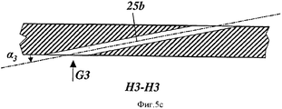
фиг.5а, 5с показывают различные продольные сечения первых отверстий пленочного охлаждения на задней кромке на стороне рабочей поверхности лопатки, показанной на фиг.2; иfiga, 5c show various longitudinal sections of the first holes of the film cooling on the trailing edge on the side of the working surface of the blade shown in figure 2; and
фиг.5b показывает границу выхода первых отверстий пленочного охлаждения в соответствии с фиг.5а, 5с.fig.5b shows the exit boundary of the first holes of the film cooling in accordance with figa, 5C.
Осуществление изобретенияThe implementation of the invention
Изобретение относится к охлаждаемой лопатке газовой турбины, которая особенно подходит для применения изобретения. Лопатка (10 на фиг.1, 2), которая является лопаткой ротора, имеет аэродинамическую секцию (12 на фиг.2), которая проходит в радиальном направлении турбины и проходит в радиальном направлении между бандажной полкой (не показана), которая ограничивает канал горячего газа, и периферической частью (11 на фиг.2) лопатки. В этом случае следует заметить, что последующие утверждения не ограничиваются исключительно лопаткой ротора, но они также могут относиться к лопатке статора, в соответствующей степени.The invention relates to a cooled blade of a gas turbine, which is particularly suitable for the application of the invention. The blade (10 in FIGS. 1, 2), which is the rotor blade, has an aerodynamic section (12 in FIG. 2) that extends in the radial direction of the turbine and extends in the radial direction between the retaining shelf (not shown), which delimits the hot channel gas, and the peripheral part (11 in figure 2) of the scapula. In this case, it should be noted that the following statements are not limited solely to the rotor blade, but they can also relate to the stator blade to an appropriate degree.
Аэродинамическая секция 12 имеет переднюю кромку 15 и заднюю кромку 16 (фиг.1) и имеет (вогнутую) рабочую поверхность 17 и (выпуклую) поверхность 18 разрежения в форме аэродинамического профиля. Корневая часть (не показана) лопатки формируется ниже платформы и используется для того, чтобы устанавливать лопатку 10 в паз, обеспеченный для этой цели в роторе (или, в случае лопатки статора, в корпусе, окружающем ротор).The
Охлаждающие каналы 19а, 19b, 19с и 20 (фиг.1), через которые протекает охлаждающий воздух, проходят в радиальном направлении во внутренней части аэродинамической секции 12, причем этот охлаждающий воздух входит в лопатку 10, когда охлаждающий воздух протекает через соответствующие входные отверстия для охлаждающего воздуха (не показаны) в корневой части лопатки. Охлаждающие каналы 19а, 19b, 19с соединяются друг с другом с помощью канальной структуры в виде серпантина. Охлаждающий воздух, протекающий через охлаждающие каналы 19а, 19b, 19 с, охлаждает лопатку 10 изнутри и выходит наружу в различных точках через охлаждающие отверстия или охлаждающие проходы. Охлаждающий канал 20 специально используется для охлаждения передней кромки 15. Для того, чтобы улучшить внутреннее охлаждение, в охлаждающих каналах 19а, b, с и 20 могут быть обеспечены турбулизаторы (не показаны) в форме наклонно расположенных ребер. Эти турбулизаторы приводят к закручиванию охлаждающего воздуха и, следовательно, к улучшению переноса тепла.The
Как изображено в показательном варианте осуществления изобретения на фиг.2, первые, сравнительно длинные охлаждающие отверстия 25 для конвекционного охлаждения обеспечиваются с распределением по ширине лопатки из охлаждающих каналов 19 и 19а, b, с в периферийной части 11 лопатки, проходя к выходу наружу на рабочей поверхности 17 лопатки 10. Вторые охлаждающие отверстия 27 проходят с выходом наружу через законцовку 33 лопатки 10 для пленочного охлаждения на поверхности 18 разрежения лопатки 10. Особенно предпочтительный охлаждающий эффект достигается с помощью комбинации конвекционного охлаждения на рабочей поверхности 17 лопатки и пленочного охлаждения на поверхности 18 разрежения лопатки.As shown in the illustrative embodiment of the invention in figure 2, the first, relatively long cooling holes 25 for convection cooling are provided with a distribution along the width of the blades from the cooling
Первые и вторые охлаждающие отверстия 25 и 27 могут иметь соответственно форму цилиндрических каналов в самом простом варианте осуществления изобретения (фиг.3а) и могут быть внедрены в лопатку 10 с помощью соответствующих способов сверления (электроэрозионный сверлильный станок, лазерное сверление). Первые охлаждающие отверстия 25 предпочтительно выполнены в форме отверстий или каналов, которые проходят наклонно вверх, для того чтобы достигнуть необходимой длины отверстия. Они предпочтительно включают в себя первый угол α1 между 25° иThe first and second cooling holes 25 and 27 may respectively have the shape of cylindrical channels in the simplest embodiment of the invention (figa) and can be embedded in the
35°, предпочтительно приблизительно 30° по отношению к внешней поверхности 17 лопатки 10.35 °, preferably approximately 30 ° with respect to the
В общем, первые и вторые охлаждающие отверстия (25а, b на фиг.2 и фиг.3b) содержат только секции в форме цилиндрических каналов с заданным первым диаметром d. Поэтому они открыты предпочтительно в окружающее лопатку 10 пространство с помощью веерообразной секции (29,30 на фигурах 4 а-с, 5а+b) канала.In general, the first and second cooling holes (25a, b in FIG. 2 and FIG. 3b) contain only sections in the form of cylindrical channels with a given first diameter d. Therefore, they are preferably open in the space surrounding the
Существует два различных вида 25а (см. фиг.4а) и 25b (см. фиг.5а) первых охлаждающих отверстий, обеспеченных на стороне (17) рабочей поверхности лопатки 10. Те из первых охлаждающих отверстий, которые располагаются снаружи задней кромки 16 лопатки 10, т.е. первые охлаждающие отверстия 25а предпочтительно открыты в окружающее лопатку 10 пространство с помощью веерообразной секции 29 канала с 3D (трехмерной) симметрией этой секции. Они показаны на фигурах 4а, 4b и 4с. Вышеуказанная веерообразная секция 29 с 3D (трехмерной) симметрией имеет первый угол 2φ1 (фиг.4b) отверстия, имеющий диапазон от 10° до 50° и предпочтительно составляющий около 24°, и второй угол φ2 (фиг.4а) отверстия, перпендикулярный вышеуказанному первому углу 2φ1 отверстия. Вышеуказанный второй угол φ2 отверстия имеет диапазон от 5° до 25° и предпочтительно составляет около 12°. Кроме того, эти первые охлаждающие отверстия 25а расположены снаружи задней кромки 16 лопатки 10 и включают в себя второй угол α2 между 15° и 45°, предпочтительно приблизительно 30° по отношению к внешней поверхности 17 лопатки 10 (фиг.4а).There are two
Те из первых охлаждающих отверстий 25b, которые располагаются на задней кромке 16 лопатки 10, предпочтительно открыты в окружающее лопатку 10 пространство с помощью веерообразной секции 30 канала с 2D (двухмерной) симметрией этой секции (фигуры 5а, 5b и 5 с). Вышеуказанная веерообразная секция 30 канала с двухмерной симметрией имеет третий угол 2φ3 отверстия (фиг.5а), имеющий диапазон от 10° до 40° и предпочтительно составляющий около 20°. Эти первые охлаждающие отверстия 25b, расположенные на задней кромке 16 лопатки 10, включают в себя третий угол λ3 (фиг.5с) между 5° и 45°, предпочтительно приблизительно 30°, по отношению к внешней поверхности 17 лопатки 10.Those of the first cooling holes 25b that are located on the trailing
Как можно увидеть на фиг.5а, те из первых охлаждающих отверстий 25b, которые располагаются на задней кромке 16 лопатки 10, имеют канал с заданной общей длиной L. Эта общая длина L подразделяется на вышеупомянутые веерообразную секцию 30 канала с двухмерной симметрией и цилиндрическую секцию второй длины L1. Соотношение L1/L этих длин находится в диапазоне от 0,2 до 0,7 и предпочтительно составляет около 0,5.As can be seen in FIG. 5a, those of the first cooling holes 25b that are located on the trailing
Фиг.2 показывает, что первые охлаждающие отверстия 25а и 25b располагаются вдоль рабочей поверхности 17 в виде ряда с (первой) периодичностью P1. Предпочтительно выбирать определенное соотношение P1/d между этой периодичностью P1 и диаметром d (см. фиг.3а) каналов охлаждающих отверстий. Это соотношение выбирается таким образом, чтобы находиться в диапазоне от 3 до 8 и предпочтительно составляет около 6.Figure 2 shows that the
Соответственно вторые охлаждающие отверстия 27 располагаются вдоль поверхности 18 разрежения в виде ряда с (второй) периодичностью Р2. И снова, соотношение Р2/d1 между второй периодичностью Р2 и диаметром d находится в диапазоне от 5 до 8 и предпочтительно составляет около 6.Accordingly, the second cooling holes 27 are located along the
В показательном варианте осуществления изобретения, проиллюстрированном на фиг.3, лопатка 10 закрывается в периферической части 11 лопатки, в ее верхней части, с помощью плоской законцовки 33, которая окружена на ее верхней поверхности периферическим ободом 32 лопатки в виде барьера. Как можно увидеть на фигурах 3а и 3b, вторые охлаждающие отверстия 27 проходят через законцовку 33 лопатки 10 в радиальном направлении. Они выполнены в форме длинных цилиндрических каналов, которые проходят наклонно вверх, и образуют угол у от 0° до 45°, предпочтительно приблизительно 30°, по отношению к продольной оси лопатки 10 (фиг.3 с).In the exemplary embodiment of the invention illustrated in FIG. 3, the
Первые охлаждающие отверстия 25 открыты в наружную область ниже законцовки 33 лопатки 10. Они выходят в окружающее лопатку 10 пространство на заданной высоте Н ниже верхнего конца периферической части 11 лопатки (фиг.3а). Соотношение H/d между вышеуказанной высотой Н и диаметром d находится в диапазоне между 5 и 10 и предпочтительно составляет около 6,5.The first cooling holes 25 are open to the outer region below the
Вторые охлаждающие отверстия 27 располагаются на противоположной поверхности и проходят через законцовку 33 лопатки 10 в радиальном направлении, открываясь в наружную область внутри обода 32 лопатки.The second cooling holes 27 are located on the opposite surface and pass through the
Также внутри обода 32 лопатки обеспечиваются пылевые отверстия 26, расположенные вдоль законцовки 33 между передней кромкой 15 и задней кромкой 16 (фиг.2). Эти пылевые отверстия 26 используются для удаления частиц пыли из внутренних охлаждающих каналов. Каждое из этих отверстий имеет диаметр d1, так что соотношение d1/d между диаметром d1 и диаметром d канала (см. фиг.3а) находится между 1,2 и 4,5.Also inside the
Как уже говорилось, лопатка 10 обеспечивается ободом 32 лопатки на периферии 11 лопатки, при этом обод 32 лопатки ограничивается периферическим барьером, имеющим заданную толщину t (фиг.3а). Ширина W между противоположными барьерами изменяется вместе с расстоянием «к» вдоль линии хорды (фиг.2) из условия, чтобы соотношение t/W находилось между 0,05 и 0,15 для к/к0 между 0 и 0,3, и соотношение t/W находилось между 0,15 и 0,3 для к/к0 больше чем 0,3 и до 1,0, при этом к0 является общей длиной всей хордовой линии. Кроме того, что касается геометрии периферии лопатки, предпочтительными являются следующие соотношения: D/W=от 0.1 до 0.3 для к/к0 от 0 до 0.3 и D/W=oт 0.1 до 0.8 для к/к0>0 до 1.0, где D означает глубину обода периферической части, a W означает ширину в соответствии с фиг.3а.As already mentioned, the
И последнее, в добавление к описанному охлаждению, такие поверхности как рабочая поверхность 17 и поверхность 18 разрежения, также как и верхняя поверхность законцовки 33 обеспечиваются термозащитным слоем (термическое защитное покрытие ТВС - Thermal Barrier Coating) 28.Lastly, in addition to the described cooling, surfaces such as the working
Claims (15)
отличающаяся тем, что первые охлаждающие отверстия (25; 25a, b) для конвекционного охлаждения выполнены на рабочей поверхности (17) лопаток (10), а вторые охлаждающие отверстия (27) для пленочного охлаждения выполнены на поверхности (18) разрежения лопаток (10), в области периферической части (11) лопатки и функционально связаны с охлаждающими каналами (19a, b, c; 20), при этом они распределены по ширине лопатки,
причем охлаждающая среда выводится наружу в области законцовки (33) и/или через законцовку (33) лопатки (10), при этом
что первые охлаждающие отверстия (25a, b) открыты в окружающее лопатку (10) пространство с помощью веерообразной секции (29, 30) канала, и
те из первых охлаждающих отверстий (25а), которые располагаются снаружи задней кромки (16) лопатки (10), открыты в окружающее лопатку (10) пространство с помощью веерообразной секции (29) канала, которая имеет трехмерную (3D) симметрию, при этом вышеуказанная веерообразная секция (29) канала с трехмерной (3D) симметрией имеет первый угол (2φ1) отверстия, имеющий диапазон от 10° до 50° и предпочтительно составляющий около 24°, и второй угол (φ2) отверстия, перпендикулярный вышеуказанному первому углу (2φ1) отверстия, при этом вышеуказанный второй угол (φ2) отверстия имеет диапазон от 5° до 25° и предпочтительно составляет около 12°, а
те из первых охлаждающих отверстий (25b), которые располагаются на задней кромке (16) лопатки (10), открыты в окружающее лопатку (10) пространство с помощью веерообразной секции (30) канала, которая имеет двухмерную (2D) симметрию, при этом вышеуказанная веерообразная секция (30) канала с двухмерной (2D) симметрией имеет третий угол (2φ3) отверстия, имеющий диапазон от 10° до 40° и предпочтительно составляющий около 20°.1. The cooled blade (10) for a gas turbine, containing an aerodynamic section (12), which extends in the radial direction of the turbine or passes in the longitudinal direction of the blade (10) between the retaining shelf and the peripheral part (11) of the blade, which is provided by the tip (33) while the aerodynamic section (12) is limited perpendicular to the longitudinal direction by means of a leading edge (15) and a trailing edge (16), and has a working surface (17) and a rarefaction surface (18) with cooling channels (19a, b, c; 20) passing E substantially radially between the shroud flange and the peripheral portion (11) into the interior of the blade airfoil section (12), and through these cooling channels (19a, b, c; 20), the cooling medium flows,
characterized in that the first cooling holes (25; 25a, b) for convection cooling are made on the working surface (17) of the blades (10), and the second cooling holes (27) for film cooling are made on the rarefaction surface (18) of the blades (10) , in the region of the peripheral part (11) of the blade and are functionally connected to the cooling channels (19a, b, c; 20), while they are distributed along the width of the blade,
moreover, the cooling medium is discharged outward in the area of the tip (33) and / or through the tip (33) of the blade (10), while
that the first cooling holes (25a, b) are open into the surrounding blade (10) of the space using a fan-shaped section (29, 30) of the channel, and
those of the first cooling holes (25a), which are located outside the trailing edge (16) of the blade (10), are opened into the space surrounding the blade (10) using a fan-shaped section (29) of the channel, which has three-dimensional (3D) symmetry, while the above the fan-shaped section (29) of the channel with three-dimensional (3D) symmetry has a first hole angle (2φ 1 ) having a range of 10 ° to 50 ° and preferably about 24 °, and a second hole angle (φ 2 ) perpendicular to the first first angle ( 2φ 1) holes, wherein said second angle (φ 2) of Verstov has a range from 5 ° to 25 ° and preferably about 12 °, and
those of the first cooling holes (25b) that are located on the trailing edge (16) of the blade (10) are opened into the space surrounding the blade (10) using a fan-shaped section (30) of the channel, which has two-dimensional (2D) symmetry, the above the fan-shaped section (30) of the channel with two-dimensional (2D) symmetry has a third opening angle (2φ 3 ) having a range of 10 ° to 40 ° and preferably about 20 °.
Applications Claiming Priority (3)
| Application Number | Priority Date | Filing Date | Title |
|---|---|---|---|
| EP09155437.8 | 2009-03-18 | ||
| EP09155437A EP2230383A1 (en) | 2009-03-18 | 2009-03-18 | Blade for a gas turbine with cooled tip cap |
| PCT/EP2010/053286 WO2010108809A1 (en) | 2009-03-18 | 2010-03-15 | Blade for a gas turbine with cooled tip cap |
Publications (2)
| Publication Number | Publication Date |
|---|---|
| RU2011141997A RU2011141997A (en) | 2013-04-27 |
| RU2531712C2 true RU2531712C2 (en) | 2014-10-27 |
Family
ID=41343214
Family Applications (1)
| Application Number | Title | Priority Date | Filing Date |
|---|---|---|---|
| RU2011141997/06A RU2531712C2 (en) | 2009-03-18 | 2010-03-15 | Blade of gas turbine with cooled tip of peripheral part of blade |
Country Status (4)
| Country | Link |
|---|---|
| US (1) | US20120070308A1 (en) |
| EP (1) | EP2230383A1 (en) |
| RU (1) | RU2531712C2 (en) |
| WO (1) | WO2010108809A1 (en) |
Families Citing this family (27)
| Publication number | Priority date | Publication date | Assignee | Title |
|---|---|---|---|---|
| US10286407B2 (en) | 2007-11-29 | 2019-05-14 | General Electric Company | Inertial separator |
| EP2547871B1 (en) * | 2010-03-19 | 2020-04-29 | Ansaldo Energia IP UK Limited | Gas turbine airfoil with shaped trailing edge coolant ejection holes and corresponding turbine |
| US10408066B2 (en) * | 2012-08-15 | 2019-09-10 | United Technologies Corporation | Suction side turbine blade tip cooling |
| US11033845B2 (en) | 2014-05-29 | 2021-06-15 | General Electric Company | Turbine engine and particle separators therefore |
| CA2949547A1 (en) | 2014-05-29 | 2016-02-18 | General Electric Company | Turbine engine and particle separators therefore |
| US10975731B2 (en) | 2014-05-29 | 2021-04-13 | General Electric Company | Turbine engine, components, and methods of cooling same |
| US9915176B2 (en) | 2014-05-29 | 2018-03-13 | General Electric Company | Shroud assembly for turbine engine |
| US20160102561A1 (en) * | 2014-10-14 | 2016-04-14 | United Technologies Corporation | Gas turbine engine turbine blade tip cooling |
| US10167725B2 (en) | 2014-10-31 | 2019-01-01 | General Electric Company | Engine component for a turbine engine |
| US10036319B2 (en) | 2014-10-31 | 2018-07-31 | General Electric Company | Separator assembly for a gas turbine engine |
| US10247011B2 (en) | 2014-12-15 | 2019-04-02 | United Technologies Corporation | Gas turbine engine component with increased cooling capacity |
| US9988910B2 (en) * | 2015-01-30 | 2018-06-05 | United Technologies Corporation | Staggered core printout |
| US9988936B2 (en) | 2015-10-15 | 2018-06-05 | General Electric Company | Shroud assembly for a gas turbine engine |
| US10428664B2 (en) | 2015-10-15 | 2019-10-01 | General Electric Company | Nozzle for a gas turbine engine |
| US10174620B2 (en) | 2015-10-15 | 2019-01-08 | General Electric Company | Turbine blade |
| US10196904B2 (en) * | 2016-01-24 | 2019-02-05 | Rolls-Royce North American Technologies Inc. | Turbine endwall and tip cooling for dual wall airfoils |
| EP3225782B1 (en) | 2016-03-29 | 2019-01-23 | Ansaldo Energia Switzerland AG | Airfoil and corresponding blading member |
| US10704425B2 (en) | 2016-07-14 | 2020-07-07 | General Electric Company | Assembly for a gas turbine engine |
| FR3062675B1 (en) * | 2017-02-07 | 2021-01-15 | Safran Helicopter Engines | HELICOPTER TURBINE HIGH PRESSURE VENTILATED VANE INCLUDING UPSTREAM DUCT AND CENTRAL COOLING CAVITY |
| US10400610B2 (en) * | 2017-02-14 | 2019-09-03 | General Electric Company | Turbine blade having a tip shroud notch |
| EP3669054B1 (en) * | 2017-08-14 | 2022-02-09 | Siemens Energy Global GmbH & Co. KG | Turbine blade and corresponding method of servicing |
| US10539026B2 (en) | 2017-09-21 | 2020-01-21 | United Technologies Corporation | Gas turbine engine component with cooling holes having variable roughness |
| US10641106B2 (en) | 2017-11-13 | 2020-05-05 | Honeywell International Inc. | Gas turbine engines with improved airfoil dust removal |
| US11542820B2 (en) * | 2017-12-06 | 2023-01-03 | General Electric Company | Turbomachinery blade and method of fabricating |
| CN112682105B (en) * | 2020-12-20 | 2022-11-11 | 中国航发四川燃气涡轮研究院 | Turbine blade structure with special-shaped micro-group air film cooling holes, preparation method of turbine blade structure and gas turbine |
| CN112682108B (en) * | 2020-12-20 | 2023-07-25 | 中国航发四川燃气涡轮研究院 | Turbine blade end wall structure with D-shaped micro-group air film cooling holes, method thereof and gas turbine |
| CN112682106B (en) * | 2020-12-20 | 2022-11-11 | 中国航发四川燃气涡轮研究院 | Turbine blade end wall structure with special-shaped micro-group air film cooling holes, method and gas turbine |
Citations (4)
| Publication number | Priority date | Publication date | Assignee | Title |
|---|---|---|---|---|
| EP0684364A1 (en) * | 1994-04-21 | 1995-11-29 | Mitsubishi Jukogyo Kabushiki Kaisha | Gas turbine rotor blade tip cooling device |
| US5626462A (en) * | 1995-01-03 | 1997-05-06 | General Electric Company | Double-wall airfoil |
| RU2106499C1 (en) * | 1995-01-11 | 1998-03-10 | Акционерное общество "Авиадвигатель" | Gas-turbine cooled blade |
| EP1059419A1 (en) * | 1999-06-09 | 2000-12-13 | General Electric Company | Triple tip-rib airfoil |
Family Cites Families (9)
| Publication number | Priority date | Publication date | Assignee | Title |
|---|---|---|---|---|
| US4893987A (en) * | 1987-12-08 | 1990-01-16 | General Electric Company | Diffusion-cooled blade tip cap |
| EP0945593B1 (en) * | 1998-03-23 | 2003-05-07 | ALSTOM (Switzerland) Ltd | Film-cooling hole |
| DE19944923B4 (en) | 1999-09-20 | 2007-07-19 | Alstom | Turbine blade for the rotor of a gas turbine |
| US6602052B2 (en) * | 2001-06-20 | 2003-08-05 | Alstom (Switzerland) Ltd | Airfoil tip squealer cooling construction |
| US6918742B2 (en) * | 2002-09-05 | 2005-07-19 | Siemens Westinghouse Power Corporation | Combustion turbine with airfoil having multi-section diffusion cooling holes and methods of making same |
| US6916150B2 (en) * | 2003-11-26 | 2005-07-12 | Siemens Westinghouse Power Corporation | Cooling system for a tip of a turbine blade |
| DE102004002327A1 (en) | 2004-01-16 | 2005-08-04 | Alstom Technology Ltd | Cooled shovel for a gas turbine |
| US7097419B2 (en) * | 2004-07-26 | 2006-08-29 | General Electric Company | Common tip chamber blade |
| US7704047B2 (en) * | 2006-11-21 | 2010-04-27 | Siemens Energy, Inc. | Cooling of turbine blade suction tip rail |
-
2009
- 2009-03-18 EP EP09155437A patent/EP2230383A1/en not_active Withdrawn
-
2010
- 2010-03-15 WO PCT/EP2010/053286 patent/WO2010108809A1/en active Application Filing
- 2010-03-15 RU RU2011141997/06A patent/RU2531712C2/en active
-
2011
- 2011-09-16 US US13/234,592 patent/US20120070308A1/en not_active Abandoned
Patent Citations (4)
| Publication number | Priority date | Publication date | Assignee | Title |
|---|---|---|---|---|
| EP0684364A1 (en) * | 1994-04-21 | 1995-11-29 | Mitsubishi Jukogyo Kabushiki Kaisha | Gas turbine rotor blade tip cooling device |
| US5626462A (en) * | 1995-01-03 | 1997-05-06 | General Electric Company | Double-wall airfoil |
| RU2106499C1 (en) * | 1995-01-11 | 1998-03-10 | Акционерное общество "Авиадвигатель" | Gas-turbine cooled blade |
| EP1059419A1 (en) * | 1999-06-09 | 2000-12-13 | General Electric Company | Triple tip-rib airfoil |
Non-Patent Citations (1)
| Title |
|---|
| 2 008. * |
Also Published As
| Publication number | Publication date |
|---|---|
| WO2010108809A1 (en) | 2010-09-30 |
| RU2011141997A (en) | 2013-04-27 |
| EP2230383A1 (en) | 2010-09-22 |
| US20120070308A1 (en) | 2012-03-22 |
Similar Documents
| Publication | Publication Date | Title |
|---|---|---|
| RU2531712C2 (en) | Blade of gas turbine with cooled tip of peripheral part of blade | |
| US4515526A (en) | Coolable airfoil for a rotary machine | |
| CA2867847C (en) | Turbine airfoil trailing edge cooling slots | |
| KR101378252B1 (en) | Serpentine cooling circuit and method for cooling tip shroud | |
| US8057181B1 (en) | Multiple expansion film cooling hole for turbine airfoil | |
| US6607355B2 (en) | Turbine airfoil with enhanced heat transfer | |
| US9206697B2 (en) | Aerofoil cooling | |
| EP1001137B1 (en) | Gas turbine airfoil with axial serpentine cooling circuits | |
| US7182576B2 (en) | Hot gas path component with mesh and impingement cooling | |
| JP5898898B2 (en) | Apparatus and method for cooling the platform area of a turbine rotor blade | |
| US7311498B2 (en) | Microcircuit cooling for blades | |
| US8360726B1 (en) | Turbine blade with chordwise cooling channels | |
| US9145773B2 (en) | Asymmetrically shaped trailing edge cooling holes | |
| US20190093487A1 (en) | Turbine airfoil with turbulating feature on a cold wall | |
| EP3124746A1 (en) | Method for cooling a turbo-engine component and turbo-engine component | |
| JP2006077767A (en) | Offset coriolis turbulator blade | |
| JP2012102726A (en) | Apparatus, system and method for cooling platform region of turbine rotor blade | |
| CA2520564A1 (en) | Stepped outlet turbine airfoil | |
| US20130302177A1 (en) | Turbine airfoil trailing edge bifurcated cooling holes | |
| US20130302176A1 (en) | Turbine airfoil trailing edge cooling slot | |
| JP6435188B2 (en) | Structural configuration and cooling circuit in turbine blades | |
| JP6010295B2 (en) | Apparatus and method for cooling the platform area of a turbine rotor blade | |
| US10662778B2 (en) | Turbine airfoil with internal impingement cooling feature | |
| CA2868536A1 (en) | Turbine airfoil trailing edge cooling slots | |
| EP1094200A1 (en) | Gas turbine cooled moving blade |
Legal Events
| Date | Code | Title | Description |
|---|---|---|---|
| PD4A | Correction of name of patent owner | ||
| PC41 | Official registration of the transfer of exclusive right |
Effective date: 20170426 |