RU2530372C2 - Belt with fluted surface for mount press - Google Patents
Belt with fluted surface for mount press Download PDFInfo
- Publication number
- RU2530372C2 RU2530372C2 RU2010148344/12A RU2010148344A RU2530372C2 RU 2530372 C2 RU2530372 C2 RU 2530372C2 RU 2010148344/12 A RU2010148344/12 A RU 2010148344/12A RU 2010148344 A RU2010148344 A RU 2010148344A RU 2530372 C2 RU2530372 C2 RU 2530372C2
- Authority
- RU
- Russia
- Prior art keywords
- grooves
- tape
- press
- bed
- length
- Prior art date
Links
Images


Classifications
-
- D—TEXTILES; PAPER
- D21—PAPER-MAKING; PRODUCTION OF CELLULOSE
- D21F—PAPER-MAKING MACHINES; METHODS OF PRODUCING PAPER THEREON
- D21F3/00—Press section of machines for making continuous webs of paper
- D21F3/02—Wet presses
- D21F3/0209—Wet presses with extended press nip
- D21F3/0218—Shoe presses
- D21F3/0227—Belts or sleeves therefor
- D21F3/0236—Belts or sleeves therefor manufacturing methods
-
- Y—GENERAL TAGGING OF NEW TECHNOLOGICAL DEVELOPMENTS; GENERAL TAGGING OF CROSS-SECTIONAL TECHNOLOGIES SPANNING OVER SEVERAL SECTIONS OF THE IPC; TECHNICAL SUBJECTS COVERED BY FORMER USPC CROSS-REFERENCE ART COLLECTIONS [XRACs] AND DIGESTS
- Y10—TECHNICAL SUBJECTS COVERED BY FORMER USPC
- Y10S—TECHNICAL SUBJECTS COVERED BY FORMER USPC CROSS-REFERENCE ART COLLECTIONS [XRACs] AND DIGESTS
- Y10S162/00—Paper making and fiber liberation
- Y10S162/901—Impermeable belts for extended nip press
Abstract
Description
ПЕРЕКРЕСТНЫЕ ССЫЛКИ НА РОДСТВЕННЫЕ ЗАЯВКИCROSS RELATIONS TO RELATED APPLICATIONS
Настоящей заявкой заявлен приоритет согласно предварительной заявке на патент США "SHOE PRESS BELT HAVING A GROOVED SURFACE" ("ЛЕНТА С ЖЕЛОБЧАТОЙ ПОВЕРХНОСТЬЮ ДЛЯ ИСПОЛЬЗОВАНИЯ В СТАНИННОМ ПРЕССЕ") (60/523,135, дата подачи: 18 ноября 2003 года) и заявке на патент США (10/988,903, дата подачи: 15 ноября 2004 года), которые следует считать включенными в настоящую заявку.This application claims priority according to the provisional US patent application "SHOE PRESS BELT HAVING A GROOVED SURFACE" (60 / 523,135 filing date: November 18, 2003) and US patent application (10 / 988,903, filing date: November 15, 2004), which should be considered included in this application.
1. Область техники1. The technical field
[0001] Настоящее изобретение относится к механизмам для извлечения воды из полотна материала и, в частности, из волокнистого полотна, перерабатываемого в бумажное изделие на бумагоделательной машине.[0001] The present invention relates to mechanisms for extracting water from a web of material and, in particular, from a fibrous web processed into a paper product on a paper machine.
2. Уровень техники2. The level of technology
[0002] Одним из процессов в технологии бумажного производства является процесс формирования волокнистого целлюлозного полотна путем осаждения волокнистой пульпы на формовочную проволочную сетку в формовочном участке бумагоделательной машины. При этом в формовочной части машины из пульпы отводится большое количество воды, после чего только что сформированное полотно поступает в прессовый участок. Прессовый участок машины содержит ряд прессующих зон контакта (nips), в которых волокнистое полотно подвергается воздействию сил сжатия, под действием которых происходит удаление воды из полотна. Наконец, полотно поступает в сушильный участок, включающий ряд нагреваемых сушильных барабанов, вокруг которых направляют полотно. При этом под действием нагретых барабанов содержание воды в полотне в результате испарения уменьшается до желаемого уровня, что приводит к образованию бумажного изделия.[0002] One of the processes in papermaking technology is the process of forming a fibrous cellulosic web by depositing fibrous pulp onto a forming wire mesh in a forming section of a paper machine. At the same time, a large amount of water is discharged from the pulp in the molding part of the machine, after which the newly formed web enters the press section. The press section of the machine contains a number of pressing contact zones (nips) in which the fibrous web is subjected to compressive forces, which remove water from the web. Finally, the web enters the drying section including a series of heated drying drums around which the web is guided. Moreover, under the action of heated drums, the water content in the web as a result of evaporation decreases to the desired level, which leads to the formation of a paper product.
[0003] Рост стоимости энергии делает исключительно желательным удаление максимально возможного количества воды из полотна еще до его поступления в сушильный участок машины. Поскольку сушильные барабаны часто нагревают изнутри при помощи водяного пара, стоимость производства указанного пара может быть значительной, особенно при необходимости удаления большого количества воды из полотна.[0003] An increase in the cost of energy makes it extremely desirable to remove as much water as possible from the web before it enters the dryer section of the machine. Since drying drums are often heated from the inside using water vapor, the cost of producing said steam can be significant, especially if it is necessary to remove large amounts of water from the web.
[0004] Традиционно прессовый участок содержит ряд зон контакта, образованных парами расположенных рядом цилиндрических прессовых валков. Недавно было обнаружено, что применение прессов станинного типа с удлиненной зоной контакта имеет преимущество перед применением нескольких зон контакта, образованных парами расположенных рядом цилиндрических прессовых валков. Это обусловлено тем, что время прохождения полотна через длинную зону контакта больше, чем время, требуемое для прохождения полотна через зону контакта, образованную прессовыми валками.[0004] Traditionally, the press section comprises a series of contact zones formed by pairs of adjacent cylindrical press rolls. Recently, it has been found that the use of bed type presses with an extended contact zone has an advantage over the use of several contact zones formed by pairs of adjacent cylindrical press rolls. This is because the passage time of the web through the long contact zone is longer than the time required for the passage of the web through the contact zone formed by the press rolls.
[0005] Чем дольше полотно может находиться под давлением в зоне контакта, тем больше воды может быть удалено в этой зоне, и, следовательно, в полотне останется меньше воды для удаления испарением в сушильном участке,[0005] The longer the web can be under pressure in the contact zone, the more water can be removed in this zone, and therefore, less water will remain in the web to be removed by evaporation in the drying section,
[0006] Настоящее изобретение относится к прессам станинного типа с длинной зоной контакта (long nip presses of the shoe type). В этой разновидности пресса с длинной зоной контакта зона контакта находится между цилиндрическим прессовым валком и дуговидной прижимной станиной пресса. Станина имеет вогнутую цилиндрическую поверхность с радиусом кривизны, близким к радиусу кривизны цилиндрического прессового валка. При близком физическом расположении валка и станины образуется зона контакта, которая в машинном направлении в 5-10 раз длиннее зоны контакта, образованной между двумя прессовыми валками. Поскольку длинная зона контакта в 5-10 раз длиннее зоны контакта, образуемой двумя валками в обычном прессе, так называемое время пребывания волокнистого полотна в длинной зоне контакта значительно больше, чем в зоне контакта двухвалкового пресса, при том же давлении на квадратный дюйм, оказываемом силами сжатия. В результате такого технологического усовершенствования было достигнуто весьма значительное повышение обезвоживания волокнистого полотна в длинной зоне контакта по сравнению с обезвоживанием, достигаемым при помощи зон контакта традиционных бумагоделательных машин.[0006] The present invention relates to long bed presses (long nip presses of the shoe type). In this type of press with a long contact zone, the contact zone is between the cylindrical press roll and the arcuate press frame of the press. The bed has a concave cylindrical surface with a radius of curvature close to the radius of curvature of the cylindrical press roll. With a close physical arrangement of the roll and the bed, a contact zone forms, which in the machine direction is 5-10 times longer than the contact zone formed between two press rolls. Since the long contact zone is 5-10 times longer than the contact zone formed by two rolls in a conventional press, the so-called residence time of the fibrous web in the long contact zone is much longer than in the contact zone of the two-roll press, at the same pressure per square inch exerted by forces compression. As a result of this technological improvement, a very significant increase in the dewatering of the fibrous web in the long contact zone was achieved compared to the dehydration achieved with the contact zones of traditional paper machines.
[0007] Для пресса станинного типа с длинной зоной контакта необходима специальная лента, например, такая, как лента, описанная в патенте США No. 5238537. Такая лента предназначена для защиты прессовой ткани, служащей для поддержки, транспортировки и обезвоживания волокнистого полотна, от ускоренного износа, обусловленного прямым скользящим контактом со стационарной станиной пресса. Такая лента должна иметь гладкую непроницаемую поверхность, находящуюся поверх стационарной пластины или перемещающуюся поверх нее на смазочной масляной пленке. Лента перемещается через зону прессования приблизительно со скоростью прессовой ткани и благодаря этому минимизируется истирание прессовой ткани о поверхность ленты.[0007] For a bed type press with a long contact area, a special tape is required, such as, for example, the tape described in US Pat. 5238537. This tape is designed to protect the press fabric, which serves to support, transport and dehydrate the fibrous web from accelerated wear caused by direct sliding contact with a stationary press frame. Such a tape should have a smooth, impermeable surface located on top of the stationary plate or moving over it on a lubricating oil film. The tape moves through the pressing zone at approximately the speed of the press fabric and thereby minimizes the abrasion of the press fabric on the surface of the tape.
[0008] Ленты, описанные в патенте США No. 5238537, изготавливают путем пропитывания текстильной основной ткани, выполненной в виде бесконечной петли, синтетической полимерной смолой. В предпочтительном варианте реализации изобретения смола образует покрытие некоторой заранее заданной толщины, нанесенное по меньшей мере на внутреннюю поверхность ленты, для защиты нитей, из которых соткана текстильная основная ткань, от непосредственного контакта с дуговидной прижимной станиной пресса с длинной зоной контакта. Именно это покрытие должно иметь гладкую непроницаемую поверхность, которая легко скользит по смазанной станине и предотвращает проникновение смазочного масла в структуру ленты, а следовательно, загрязнение прессовой ткани или тканей, а также волокнистого полотна.[0008] The tapes described in US patent No. 5238537, is made by impregnating a textile base fabric, made in the form of an endless loop, with a synthetic polymer resin. In a preferred embodiment of the invention, the resin forms a coating of a certain predetermined thickness, applied at least on the inner surface of the tape, to protect the threads from which the textile main fabric is woven from direct contact with the arcuate press frame of the press with a long contact area. It is this coating that should have a smooth, impermeable surface that glides easily along the greased bed and prevents the penetration of lubricating oil into the structure of the tape, and consequently, contamination of the press fabric or fabrics, as well as the fibrous web.
[0009] Основная ткань ленты, описанная в патенте США No. 5238 537, может быть соткана из моноволоконных пряжи в виде однослойного или многослойного переплетения, которое должно быть достаточно открытым с тем, чтобы обеспечить возможность полной пропитки сукна. Это позволяет снизить вероятность возникновения пустот в готовой ленте. При наличии таких пустот смазка, находящаяся между лентой и станиной, может проникать через ленту и загрязнять прессовую ткань или ткани, а также волокнистое полотно. Основная ткань может быть соткана в виде плоской ленты, а потом может быть сшита в виде бесконечной петли, или она может быть соткана в виде бесконечной трубчатой петли.[0009] The main fabric of the tape described in US patent No. 5238 537, can be woven from monofilament yarns in the form of a single-layer or multi-layer weave, which should be sufficiently open to allow complete impregnation of the cloth. This reduces the likelihood of voids in the finished tape. In the presence of such voids, the lubricant between the belt and the bed can penetrate the belt and contaminate the press fabric or fabrics, as well as the fibrous web. The main fabric can be woven in the form of a flat ribbon, and then can be sewn in the form of an endless loop, or it can be woven in the form of an endless tubular loop.
[0010] В результате отверждения пропитывающий материал закрепляется на основной ткани по существу за счет механического сцепления, при этом отвержденный пропитывающий материал обволакивает нити основной ткани. Кроме того, между отвержденным пропитывающим материалом и материалом нитей основной ткани может возникать химическое сцепление благодаря связующему или слипание.[0010] As a result of curing, the impregnating material is fixed to the main fabric essentially by mechanical adhesion, while the cured impregnating material envelops the threads of the main fabric. In addition, chemical adhesion may occur between the cured impregnating material and the filament material of the main fabric due to a binder or sticking.
[0011] В зависимости от размеров прессов с длинной зоной контакта ленты, предназначенные для установки на таких прессах, имеют длину, измеренную в машинном направлении вдоль бесконечной петли, образованной указанной лентой, приблизительно составляющую от 13 до 35 футов (приблизительно от 4 до 11 метров), и ширину, измеренную в поперечном направлении бесконечной петли, приблизительно составляющую от 100 до 450 дюймов (приблизительно от 250 до 1125 см). Изготовление таких лент усложняется тем, что основная ткань должна быть сформирована в бесконечную петлю еще до ее пропитывания синтетической полимерной смолой.[0011] Depending on the size of the presses with a long contact area, the tapes intended for installation on such presses have a length measured in the machine direction along the endless loop formed by said tape, approximately 13 to 35 feet (approximately 4 to 11 meters) ), and the width measured in the transverse direction of the endless loop, approximately comprising from 100 to 450 inches (approximately from 250 to 1125 cm). The manufacture of such tapes is complicated by the fact that the main fabric must be formed into an endless loop before it is impregnated with a synthetic polymer resin.
[0012] В процессе производства часто возникает необходимость изготавливать ленту с покрытием некоторой заранее заданной толщины, нанесенным как на внутреннюю, так и на внешнюю поверхность ленты. При нанесении покрытия на обе стороны ленты ее текстильная основная ткань будет расположена близко к нейтральной линии сгиба ленты или совпадать с этой линией. В этом случае вероятность отслоения покрытия от любой стороны ленты под действием внутреннего напряжения, возникающего при прохождении ленты вокруг валка или при подобном изгибе, имеющем место в бумагоделательной машине, будет меньше.[0012] In the manufacturing process, it is often necessary to produce a tape coated with a predetermined thickness applied to both the inner and the outer surfaces of the tape. When coating on both sides of the tape, its textile base fabric will be located close to the neutral line of the fold of the tape or coincide with this line. In this case, the likelihood of peeling of the coating from either side of the tape under the influence of internal stress arising from the passage of the tape around the roll or with a similar bend taking place in a paper machine will be less.
[0013] Кроме того, нанесение на внешнюю сторону ленты покрытия из смолы, имеющего некоторую заранее заданную толщину, позволяет выполнить в таком покрытии желобки, глухие сверленые отверстия или иные полости так, чтобы при этом не обнажить тканой текстильной основной ткани. Указанные желобки или другие полости позволяют временно удерживать воду, отжатую из полотна в прессовой зоне. На практике, для некоторых конфигураций пресса с длинной зоной контакта присутствие на внешней поверхности ленты некоторого объема пустот, благодаря наличию желобков, сверленых отверстий и подобных деталей, является необходимым условием работы.[0013] In addition, applying a resin coating having a predetermined thickness to the outside of the tape allows grooves, blind drilled holes or other cavities to be formed in such a coating so as not to expose the woven textile base fabric. These grooves or other cavities allow you to temporarily hold water, squeezed from the canvas in the press zone. In practice, for some press configurations with a long contact zone, the presence on the outer surface of the tape of a certain volume of voids, due to the presence of grooves, drilled holes and similar parts, is a necessary condition for operation.
[0014] В данной области техники известны ленты с множеством желобков, применяемые в прессах с длинной зоной контакта. Например, в патенте США No. 4946731, Dutt, описана такая лента, применяемая в прессе с длинной зоной контакта, которая содержит основную ткань, включающую проходящую по меньшей мере в одном из направлений, а именно в машинном или поперечном, штапельную нить из штапельных волокон. При нанесении покрытия из полимерной смолы на основную ткань отдельные штапельные волокна выступают из штапельных нитей наружу в обволакивающий покрывающий материал. Затем в покрытии, нанесенном на внешнюю поверхность ленты, вырезают желобки в машинном направлении. Так называемые контактные площадки (land areas), отделяющие желобки друг от друга, соединены с лентой за счет этих штапельных волокон, что уменьшает вероятность отслоения покрытия.[0014] A plurality of grooves are known in the art for use in presses with a long contact area. For example, in US Pat. 4946731, Dutt, describes such a tape used in a press with a long contact zone, which contains the main fabric, including passing through at least one of the directions, namely in the machine or cross, a staple thread of staple fibers. When polymer resin is coated on the base fabric, individual staple fibers protrude from the staple fibers outward into the enveloping coating material. Then, in the coating applied to the outer surface of the tape, grooves are cut in the machine direction. So-called contact areas (land areas) that separate the grooves from each other are connected to the tape by these staple fibers, which reduces the likelihood of delamination of the coating.
[0015] В другом примере из патента США No. 6428874, McGahern et al. описана пропитанная смолой бесконечная лента, предназначенная для использования в прессе станинного типа с длинной зоной контакта, содержащая основную структуру, пропитанную полимерным смолистым материалом, который придает ленте непроницаемость относительно текучих сред, таких как масло, вода и воздух. Полимерный смолистый материал образует слои на внутренней и внешней сторонах основной структуры. Внутренний слой является гладким, а внешний слой содержит первичные желобки для временного удержания воды, отжатой из бумажного полотна. Первичные желобки отделены контактными площадками, которые содержат вторичные желобки, проходящие поперек их для снижения напряжения, служащего причиной возникновения усталости при сжатии и растрескивания под действием напряжения.[0015] In another example from US patent No. 6428874, McGahern et al. An endless belt impregnated with resin is described for use in a press of a bed type with a long contact zone, containing a base structure impregnated with a resinous resinous material that imparts impermeability to the tape relative to fluids such as oil, water and air. Polymeric resinous material forms layers on the inner and outer sides of the main structure. The inner layer is smooth, and the outer layer contains primary grooves to temporarily hold water squeezed from the paper web. The primary grooves are separated by contact pads that contain secondary grooves extending across them to reduce stress, causing compression fatigue and cracking under the action of stress.
[0016] Соответственно, ленты с желобчатой поверхностью, предназначенные для применения в станинных прессах, имеют целый ряд преимуществ перед лентами без желобков, например, такие ленты позволяют улучшить водоотводящие свойства, профиль листа, оптимизацию влажности сукна и увеличить срок его службы.[0016] Accordingly, grooved surface tapes for use in bed presses have a number of advantages over grooveless ribbons, for example, such ribbons can improve drainage properties, sheet profile, optimize the moisture content of the cloth and increase its service life.
[0017] Однако для некоторых целей, в частности для низкоскоростных бумагоделательных машин, преимущества желобчатых лент менее очевидны. В частности, для использования в прессах, для которых наблюдается разбрызгивание на участке входа в зону контакта (например, в обращенных прессах), более предпочтительным может быть применение лент, на поверхности которых высверлены глухие круглые отверстия, вместо вышеописанных лент с желобчатой поверхностью.[0017] However, for some purposes, in particular for low speed paper machines, the advantages of grooved tapes are less obvious. In particular, for use in presses for which spraying is observed at the entrance to the contact zone (for example, inverted presses), it may be more preferable to use tapes with blind round holes drilled on their surface instead of the above tapered tapes.
[0018] Иными словами, при подаче прессовой ткани в зону прижимного контакта происходит разбрызгивание на участке ввода в зону контакта. Прессовый валок отжимает воду из полотна, которая затем попадает в прессовую ткань и далее попадает в желобки. Из-за того, что желобки проходят непрерывно по всей длине ленты на участках входа и выхода из зоны контакта происходит разбрызгивание воды.[0018] In other words, when the press fabric is fed into the pressure contact zone, spraying occurs at the entry portion into the contact zone. The press roll squeezes water from the web, which then enters the press fabric and then enters the grooves. Due to the fact that the grooves pass continuously along the entire length of the tape in the areas of entry and exit from the contact zone, water is sprayed.
[0019] Разбрызгивание на участке входа в зону контакта приводит к снижению объема пустот в прессовой ткани, что, в свою очередь, приводит к меньшему обезвоживанию полотна.[0019] Spraying at the entrance to the contact zone leads to a decrease in the volume of voids in the press fabric, which, in turn, leads to less dewatering of the web.
[0020] В соответствии с настоящим изобретением предложено устранить указанный недостаток при помощи ленты с желобчатой поверхностью, предназначенной для использования в станинном прессе, в которой некоторые из желобков могут быть выполнены прерывными, а их длина может быть меньше длины дуговидной прижимной станины пресса с длинной зоной контакта. Область зоны контакта, на которую оказывается наибольшее давление (и в которой происходит наибольшее удаление воды), находится перед участком выхода из зоны контакта. В тот момент, когда желобок покидает зону контакта, отверстие указанного желобка может находиться вне участка ввода в зону контакта или вход в зону контакта может быть заблокирован из-за того, что длина желобка меньше, чем длина дуговидной прижимной станины, и, следовательно, меньше длины зоны прижимного контакта. Поскольку вход в зону контакта блокирован (не имеет сообщения с атмосферой), разбрызгивание воды на участке ввода в зону контакта уменьшено или совершенно отсутствует, а гидравлическое давление в прессовой ткани увеличивается, что приводит к эффективному обезвоживанию полотна по мере того, как сегмент желобка в поверхности ленты покидает зону контакта. Соответственно, прерывистые желобки, предлагаемые в соответствии с настоящим изобретением, снижают или устраняют разбрызгивание воды на участке входа в зону контакта и увеличивают эффективность обезвоживания, что приводит к равномерному профилю высушивания листа в поперечном направлении относительно машины, результатом чего являются такие положительные стороны, как экономия энергии и увеличение производительности при изготовлении бумаги.[0020] In accordance with the present invention, it is proposed to eliminate this drawback with a grooved surface tape intended for use in a bed press, in which some of the grooves may be discontinuous and their length may be less than the length of the arc-shaped press bed of the press with a long zone contact. The area of the contact zone to which the greatest pressure is exerted (and in which the greatest removal of water occurs) is in front of the exit area from the contact zone. At the moment when the groove leaves the contact zone, the opening of the specified groove may be outside the entry area into the contact zone or the entrance to the contact zone may be blocked due to the fact that the length of the groove is less than the length of the arcuate clamping bed, and therefore less pressure contact zone lengths. Since the entrance to the contact zone is blocked (has no communication with the atmosphere), water spray at the entrance to the contact zone is reduced or completely absent, and the hydraulic pressure in the press fabric increases, which leads to effective dewatering of the web as the groove segment in the surface the tape leaves the contact area. Accordingly, the intermittent grooves of the present invention reduce or eliminate water spray at the entrance to the contact zone and increase the dewatering efficiency, which leads to a uniform drying profile of the sheet in the transverse direction relative to the machine, resulting in positive aspects such as savings energy and increased productivity in the manufacture of paper.
[0021] Желобки в вышеуказанной предлагаемой ленте могут проходить в направлении, по существу параллельном машинному направлению (MD). В других вариантах реализации изобретения желобки в предлагаемой ленте могут быть ориентированы в поперечном направлении (CD) машины и могут быть непрерывными или прерывистыми.[0021] The grooves in the above proposed tape may extend in a direction substantially parallel to the machine direction (MD). In other embodiments of the invention, the grooves in the tape of the invention can be oriented in the transverse direction (CD) of the machine and can be continuous or discontinuous.
КРАТКОЕ ОПИСАНИЕ ИЗОБРЕТЕНИЯSUMMARY OF THE INVENTION
[0022] Соответственно, настоящее изобретение относится к ленте, которая может быть использована в станинном прессе с длинной зоной контакта. Лента содержит по меньшей мере один слой, например основную структуру, которая может быть выполнена в виде бесконечной петли. Пресс с длинной зоной контакта может включать дуговидную прижимную станину. Полимерным смолистым материалом пропитывают или покрывают по меньшей мере одну поверхность слоя ленты и формируют на ней внешний слой или покрытие.[0022] Accordingly, the present invention relates to a tape that can be used in a bed press with a long contact area. The tape contains at least one layer, for example, the main structure, which can be made in the form of an endless loop. A press with a long contact area may include an arcuate clamping bed. At least one surface of the tape layer is impregnated or coated with a resinous resin material and an outer layer or coating is formed on it.
[0023] Внешний слой может содержать множество желобков, ориентированных по существу в машинном направлении (MD), причем длина некоторых желобков меньше длины дуговидной прижимной станины.[0023] The outer layer may comprise a plurality of grooves oriented essentially in the machine direction (MD), the length of some grooves being less than the length of the arcuate clamping bed.
[0024] В других вариантах реализации предложенная согласно изобретению лента содержит множество непрерывных или прерывистых желобков, ориентированных по существу в поперечном направлении (CD) машины.[0024] In other embodiments, the inventive tape comprises a plurality of continuous or discontinuous grooves oriented substantially in the transverse direction (CD) of the machine.
[0025] Далее настоящее изобретение будет описано более подробно со ссылками на нижеследующие чертежи, на которых одинаковыми позициями обозначены одинаковые элементы и части.[0025] The present invention will now be described in more detail with reference to the following drawings, in which like elements and parts are denoted by like numerals.
КРАТКОЕ ОПИСАНИЕ ЧЕРТЕЖЕЙBRIEF DESCRIPTION OF THE DRAWINGS
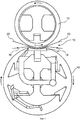
[0026] На Фиг.1 показан вид сбоку в разрезе пресса с длинной зоной контакта.[0026] Figure 1 shows a sectional side view of a press with a long contact area.
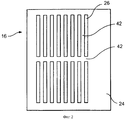
На Фиг.2 показан вид сверху ленты с множеством желобков, расположенных в соответствии с одним из вариантов реализации настоящего изобретения.Figure 2 shows a top view of a tape with many grooves located in accordance with one embodiment of the present invention.
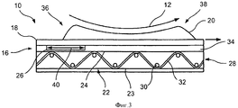
На Фиг.3 показан разрез деталей, изображенных на Фиг.1, на котором показан желобок в зоне контакта.Figure 3 shows a section of the parts shown in figure 1, which shows the groove in the contact zone.
На Фиг.4 показан разрез деталей, изображенных на Фиг.1, на котором показан желобок, закрытый зоной контакта.Figure 4 shows a section of the parts shown in figure 1, which shows the groove closed by the contact zone.
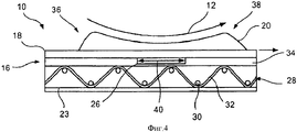
На Фиг.5 показан разрез деталей, изображенных на Фиг.1, на котором показан желобок, выходящий из зоны контакта.Figure 5 shows a section of the parts shown in Figure 1, which shows the groove emerging from the contact zone.
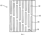
На Фиг.6 показан вид сверху ленты с множеством желобков, расположенных в соответствии еще с одним из вариантов реализации настоящего изобретения.Figure 6 shows a top view of a tape with many grooves located in accordance with another embodiment of the present invention.
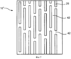
На Фиг.7 показан вид сверху ленты с множеством желобков, расположенных в соответствии еще с одним из вариантов реализации настоящего изобретения.7 shows a top view of a tape with many grooves located in accordance with another embodiment of the present invention.
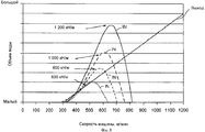
На Фиг.8 изображена диаграмма зависимости объема воды, разбрызгиваемой на входе в зону контакта и на выходе из зоны контакта, от скорости машины и прижимной нагрузки на ленту, в которой изготовлены непрерывные желобки.On Fig shows a diagram of the dependence of the volume of water sprayed at the entrance to the contact zone and at the exit of the contact zone, on the speed of the machine and the pressure load on the tape, in which continuous grooves are made.
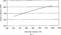
На Фиг.9 изображена диаграмма зависимости скорости исчезновения разбрызгивания на входе в зону контакта от нагрузки на ленту, в которой изготовлены непрерывные желобки.Figure 9 shows a diagram of the dependence of the rate of disappearance of spraying at the entrance to the contact zone from the load on the tape, in which continuous grooves are made.
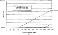
На Фиг.10 изображена диаграмма зависимости объема воды, распыляемой на входе в зону контакта и на выходе из зоны контакта, от скорости машины и нагрузки на ленту, для ленты согласно настоящему изобретению.Figure 10 shows a diagram of the dependence of the volume of water sprayed at the entrance to the contact zone and at the exit of the contact zone, on the speed of the machine and the load on the tape, for the tape according to the present invention.
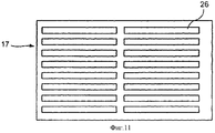
На Фиг.11 показан вид сверху ленты с множеством желобков, расположенных в соответствии еще с одним из вариантов реализации настоящего изобретения.Figure 11 shows a top view of a tape with many grooves located in accordance with another embodiment of the present invention.
На Фиг.11а показан вид сверху ленты с множеством желобков, расположенных в соответствии с одним из вариантов реализации настоящего изобретения.On figa shows a top view of a tape with many grooves located in accordance with one of the options for implementing the present invention.
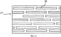
На Фиг.12 показан вид сверху ленты с множеством желобков, которые расположены в соответствии с одним из вариантов реализации настоящего изобретения.On Fig shows a top view of a tape with many grooves, which are located in accordance with one of the embodiments of the present invention.
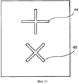
На Фиг.13 показан вид сверху ленты с множеством желобков, которые расположены в соответствии с одним из вариантов реализации настоящего изобретения.On Fig shows a top view of a tape with many grooves, which are located in accordance with one of the embodiments of the present invention.
На Фиг.14 показан вид сверху ленты с множеством желобков, которые расположены в соответствии с одним из вариантов реализации настоящего изобретения.On Fig shows a top view of a tape with many grooves, which are located in accordance with one of the embodiments of the present invention.
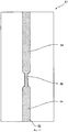
На Фиг.15 показан вид сверху ленты в соответствии с одним из вариантов реализации настоящего изобретения.On Fig shows a top view of the tape in accordance with one embodiment of the present invention.
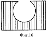
На Фиг.16 изображено поперечное сечение желобка, предлагаемого в соответствии с одним из вариантов реализации настоящего изобретения.On Fig shows a cross section of a groove, proposed in accordance with one of the embodiments of the present invention.
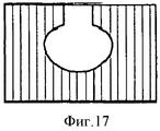
На Фиг.17 изображено поперечное сечение желобка, предлагаемого в соответствии с одним из вариантов реализации настоящего изобретения.On Fig shows a cross section of a groove proposed in accordance with one of the options for implementing the present invention.
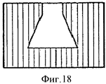
На Фиг.18 изображено поперечное сечение желобка, предлагаемого в соответствии с одним из вариантов реализации настоящего изобретения.On Fig shows a cross section of a groove, proposed in accordance with one of the embodiments of the present invention.
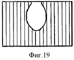
На Фиг.19 изображено поперечное сечение желобка, предлагаемого в соответствии с одним из вариантов реализации настоящего изобретения.On Fig shows a cross section of a groove, proposed in accordance with one of the embodiments of the present invention.
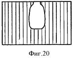
На Фиг.20 изображено поперечное сечение желобка, предлагаемого в соответствии с одним из вариантов реализации настоящего изобретения.On Fig depicts a cross section of a groove proposed in accordance with one of the embodiments of the present invention.
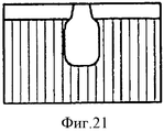
На Фиг.21 изображено поперечное сечение желобка, предлагаемого в соответствии с одним из вариантов реализации настоящего изобретения.On Fig shows a cross section of a groove, proposed in accordance with one of the embodiments of the present invention.
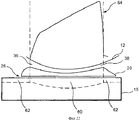
На Фиг.22 показано поперечное сечение пресса с прижимной станиной и ленты, предлагаемой в соответствии еще с одним вариантом реализации настоящего изобретения.On Fig shows a cross section of a press with a clamping bed and tape, proposed in accordance with another embodiment of the present invention.
На Фиг.23 показан вид сверху ленты с множеством желобков, которые расположены в соответствии с одним из вариантов реализации настоящего изобретения.On Fig shows a top view of a tape with many grooves, which are located in accordance with one of the embodiments of the present invention.
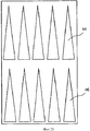
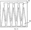
На Фиг.24 показан вид сверху ленты с множеством желобков, которые расположены в соответствии с одним из вариантов реализации настоящего изобретения.On Fig shows a top view of a tape with many grooves, which are located in accordance with one of the options for implementing the present invention.
На Фиг.25 показан вид сверху ленты с множеством желобков, которые расположены в соответствии с одним из вариантов реализации настоящего изобретения.On Fig shows a top view of a tape with many grooves, which are located in accordance with one of the embodiments of the present invention.
На Фиг.26 показан вид сверху ленты с множеством желобков, которые расположены в соответствии с одним из вариантов реализации настоящего изобретения.On Fig shows a top view of a tape with many grooves, which are located in accordance with one of the embodiments of the present invention.
На Фиг.27 показан вид сверху ленты с множеством желобков, которые расположены в соответствии с одним из вариантов реализации настоящего изобретения.On Fig shows a top view of a tape with many grooves, which are located in accordance with one of the embodiments of the present invention.
На Фиг.28 показан вид сверху ленты с множеством желобков, которые расположены в соответствии с одним из вариантов реализации настоящего изобретения.On Fig shows a top view of a tape with many grooves, which are located in accordance with one of the embodiments of the present invention.
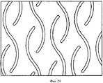
На Фиг.29 показан вид сверху ленты с множеством желобков, которые расположены в соответствии с одним из вариантов реализации настоящего изобретения.On Fig shows a top view of a tape with many grooves, which are located in accordance with one of the embodiments of the present invention.
ПОДРОБНОЕ ОПИСАНИЕ ПРЕДПОЧТИТЕЛЬНОГО ВАРИАНТА РЕАЛИЗАЦИИDETAILED DESCRIPTION OF A PREFERRED EMBODIMENT
[0027] На Фиг.1 показан вид сбоку в разрезе пресса с длинной зоной контакта, предназначенного для обезвоживания волокнистого полотна, перерабатываемого на бумагоделательной машине в бумажное изделие. Зона 10 прижимного контакта ограничена гладким цилиндрическим прессовым валком 12 и дуговидной прижимной станиной 14. Дуговидная прижимная станина 14 имеет приблизительно такой же радиус кривизны, что и цилиндрический прессовый валок 12. Для регулирования подачи нагрузки на зону 10 контакта расстояние между цилиндрическим прессовым валком 12 и дуговидной прижимной станиной 14 можно регулировать при помощи гидравлического привода и т.п., присоединенного к дуговидной прижимной станине 14. Гладкий цилиндрический прессовый валок 12 может представлять собой управляемый валок с выпуклой бочкой, пригнанный по дуговидной прижимной станине 14, для получения равномерного профиля давления в поперечном направлении.[0027] FIG. 1 is a cross-sectional side view of a press with a long contact zone for dewatering a fibrous web processed on a paper machine into a paper product. The
[0028] Лента 16, применяемая в прессе с длинной зоной контакта, проходит в виде замкнутой петли через зону 10 контакта, отделяя цилиндрический прессовый валок 12 от дуговидной прижимной станины 14. Вместе с ней через зону 10 контакта проходят, как указано стрелками на Фиг.1, прессовая ткань 18 и волокнистое полотно 20, перерабатываемое в бумажный лист. Волокнистое полотно 20, поддерживаемое прессовой тканью 18, входит в непосредственный контакт с гладким цилиндрическим прессовым валком 12 в зоне 10 контакта. В других вариантах реализации изобретения через зону 10 контакта может проходить волокнистое полотно 20, расположенное между двумя прессовыми тканями 18 (вторая прессовая ткань не показана). Лента 16, применяемая в прессе с длинной зоной контакта, также проходящая через зону 10 контакта, как указано стрелками на Фиг.1, т.е. по часовой стрелке, защищает ткань 18 от непосредственного скользящего контакта с дуговидной прижимной станиной 14, и может скользить поверх станины на пленке смазочного масла. Соответственно, лента 16, применяемая в прессе с длинной зоной контакта, может быть непроницаема для масла, чтобы не допустить загрязнения им прессовой ткани 18 и волокнистого полотна 20.[0028] The
[0029] На Фиг.2 показан вид сверху ленты 16, предлагаемой в соответствии с одним вариантом реализации настоящего изобретения. Лента 16 имеет внешнюю поверхность 24. На верхнюю поверхность 24 нанесено множество желобков 26, проходящих в машинном направлении вокруг ленты 16 и для временного удержания воды, отжатой из волокнистого полотна 20 в зоне 10 контакта. Более подробно желобки 26 будут описаны ниже.[0029] Figure 2 shows a top view of the
[0030] На Фиг.3-5 показан механизм обезвоживания в зоне 10 контакта станинного пресса, реализуемый в три этапа, во время которых один из желобков 26 входит в зону 10 контакта и выходит из нее.[0030] Figure 3-5 shows the dehydration mechanism in the
[0031] На Фиг.3 показан разрез ленты 16 в тот момент, когда желобок 26 входит в зону 10 контакта. На Фиг.3-5 последовательно показано, как желобок 26 входит в зону 10 контакта на участке 36 ввода в зону 10 контакта и как желобок 26 выходит из зоны 10 контакта на участке 38 выхода из зоны 10 контакта.[0031] Figure 3 shows a section of the
[0032] На Фиг.3 также показан разрез ленты 16. Лента 16 может содержать по меньшей мере один основный слой 28. При этом кроме полимерного смоляного покрытия 34 лента 16 также может содержать дополнительные слои.[0032] FIG. 3 also shows a section through a
[0033] Слой 28 может быть соткан из нитей 30 (видимых сбоку на Фиг.3), расположенных в поперечном направлении или в направлении поперек машины, и нитей 32, расположенных в продольном или машинном направлении.[0033] The
[0034] Слой 28 может быть тканым, при этом поперечные нити являются основными и переплетены поверх, под и между продольными нитями 32; уточные нити входят в состав одинарного переплетения (single weave). Однако следует понимать, что слой 28 может быть соткан простым переплетением, а потом соединен швом в бесконечную форму. Следует также понимать, что слой 28 может быть соткан в виде двойного переплетения (duplex weave) или любого другого переплетения, которое может быть использовано для изготовления лент, применяемых в одежде бумагоделательных машин.[0034] The
[0035] Еще в одном варианте реализации изобретения слой 28 может представлять собой нетканую структуру в виде совокупности поперечных и продольных нитей, которые могут быть соединены друг с другом посредством связующего в местах взаимного пересечения с образованием ткани. Далее, слой 28 может представлять собой трикотажное полотно или плетеную ткань или ленту из спиральных петель, подобную ткани, описанной в патенте США No. 4567077, Gauthier, содержание которого включено в настоящее описание по ссылке. Слой 28 также может быть получен экструзией из полимерного смолистого материала в виде листа или мембраны, в которой затем могут быть выполнены отверстия. Еще в одном варианте реализации изобретения по меньшей мере один слой 28 может содержать нетканые сетчатые полотна, подобные полотнам, описанным в патенте США No. 4427734, Johnson, содержание которого включено в настоящее описание по ссылке.[0035] In another embodiment, the
[0036] Далее, слой 28 может быть получен при спиральном наматывании полосы тканого, нетканого, трикотажного, плетеного, экструдированного или нетканого сетчатого материала в соответствии со способами, описанными в патенте США No. 5,360,656, Rexfelt et al., содержание которого включено в настоящее описание по ссылке. Соответственно, основный слой 28 может содержать спирально намотанную полосу, в которой каждый спиральный виток соединен со следующим витком непрерывным швом, в результате чего получают бесконечную в продольном направлении основную структуру 28. Прессовая лента, содержащая основную структуру такого вида, описана в патентах США No. 5792323 и 5837080, содержания которых включены в настоящее описание по ссылке.[0036] Further, the
[0037] Смолу, такую как полимерная смола 34, наносят в виде покрытия, пропитывают или наносят каким-либо иным способом по меньшей мере на одну поверхность ленты 16. Полимерная смола 34 может быть нанесена в виде покрытия или каким-либо иным способом на внешнюю поверхность 24 ленты 16, то есть на поверхность, которая контактирует с прессовой тканью 18 при использовании ленты 16 на прессе с длинной зоной контакта. Кроме того, полимерный смолистый слой 23 может быть нанесен в виде покрытия или каким-либо иным способом на внутреннюю поверхность 22 ленты 16, то есть на поверхность, которая перемещается поверх дуговидной прижимной станины 14 во время использования ленты 16 на прессе с длинной зоной контакта. Полимерный смолистый слой 23 может пропитывать слой 28, что делает ленту 16 непроницаемой для масла, воды и т.п.[0037] A resin, such as a
[0038] Полимерные смолистые покрытия 34 и 23 из полимерной смолы могут представлять собой полиуретан и составлять композицию из 100% твердого полиуретана. Применение твердой системы из 100% смолы, в которой по определению отсутствует материал растворителя, предотвращает образование в полимерной смоле пузырей во время процесса отверждения, который проводят после нанесения смолы на слой 28.[0038] The
[0039] После отверждения полимерной смолы внутренняя поверхность 22 и/или внешняя поверхность 24 может быть отшлифована и отполирована для создания на полимерном смолистом покрытии гладкой однородной поверхности.[0039] After curing the polymer resin, the
[0040] После отверждения полимерной смолы во внешней поверхности 24 ленты 16 могут быть вырезаны желобки 26. В других вариантах реализации изобретения желобки 26 могут быть выполнены прессованием во внешней поверхности 24 при помощи прессующего устройства до отверждения полимерной смолы, или указанные желобки могут быть сформованы на внешней поверхности 24 (если ленту 16 изготовляют формованием). Следует понимать, что известны и другие способы изготовления желобков 26.[0040] After the polymer resin has cured, the
[0041] Далее, по меньшей мере в одном варианте реализации настоящего изобретения желобки 26 могут быть прерывистыми. Иными словами, желобки 26 могут быть отделены друг от друга контактными площадками 42, которые представляют собой не содержащие желобков области между соседними (и таким образом последовательными) желобками. Желобки 26 могут быть сформированы как в машинном направлении ленты, так и поперечном направлении ленты. В одном предпочтительном варианте реализации изобретения, показанном на Фиг.3-5, в котором желобки сформированы в машинном направлении, в ленте в машинном направлении выполнены желобки 26 длиной 40, не превышающей длину станины 14 (на Фиг.1), то есть приблизительно, длина желобков составляла одну треть, одну вторую, две трети и т.д. от длины станины. Например, если длина типичной дуговидной прижимной станины составляет приблизительно 250 мм, то длина 40 желобка 26 может составлять приблизительно 125 мм. Аналогично, на Фиг.11 показан вариант реализации, в котором желобки 26 сформированы в поперечном направлении относительно машины.[0041] Further, in at least one embodiment of the present invention, the
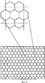
[0042] Форма, размеры, расстояние между желобками 26 и ориентация желобков 26 может варьироваться в зависимости от применения пресса с длинной зоной контакта и/или от желаемого снижения величины разбрызгивания на участке ввода в зону контакта, и от эффективности обезвоживания. Необходимо отметить, что желобки только зигзагообразной или синусоидальной формы без прямолинейных участков обеспечивают больший объем, а следовательно, обладают улучшенной способностью удерживать воду, удаляемую из волокнистого полотна, чем прямолинейные желобки или желобки комбинированной формы с зигзагообразными или синусоидальными и прямолинейными участками. Лента согласно настоящему изобретению снижает разбрызгивание на участке ввода в зону контакта, поскольку длина желобка в машинном направлении меньше, чем соответствующая длина станинной части пресса, так что при возрастании давления внутри желобка при его прохождении через станинную часть пресса, конец желобка на входе в зону контакта накрывается раньше, чем противоположный конец желобка (в машинном направлении) выходит из зоны контакта. Для выполнений указанной функции необходимо, чтобы весь желобок помещался в области под станинным прессом. Желобок синусоидальной или зигзагообразной формы, который помещается в этой области, имеет больший объем, чем прямолинейный желобок той же длины и глубины, поскольку он изогнут в области станинного пресса. Выполняя желобки только с зигзагообразными или синусоидальными участками, возможно увеличить объем желобка и, следовательно, увеличить объем жидкости, которую желобок способен удержать. Аналогичным образом желобки изогнутой формы, такой как круглая форма или сотовая структура, которые могут поместиться в области, образованной станинным прессом, также обладают большим объемом по сравнению с прямолинейными желобками. Таким образом, желобки, показанные на Фиг 23-25 и 27-29, обладают большим объемом и, следовательно, обеспечивают лучшее удаление воды по сравнению с прямолинейными желобками или желобками, содержащими прямолинейный участок.[0042] The shape, dimensions, the distance between the
[0043] Как уже было сказано выше и показано на Фиг.3, желобок 26 входит в зону 10 контакта на участке 36 ввода и выходит из зоны 10 контакта на участке 38 выхода. Участок 36 ввода характеризуется зоной низкого давления. Когда волокнистое полотно 20 входит в зону 10 контакта, давление, создаваемое валком 12 и станиной 14, заставляет воду, содержащуюся в полотне 20, вытекать из полотна в прессовую ткань 18, которая находится в контакте с лентой 16. При этом желобок 26 вбирает в себя воду из прессовой ткани 18.[0043] As already mentioned above and shown in FIG. 3, the
[0044] На Фиг.4 показан разрез ленты 16 в тот момент, когда желобок 26 закрыт зоной 10 контакта. Желобок 26 входит в гидростатическую зону, в которой вода, отжатая из полотна 20 и из прессовой ткани 18, находится под давлением. Желобок 26 вбирает в себя воду до полного заполнения его полости.[0044] Figure 4 shows a section of the
[0045] На Фиг.5 показан разрез ленты 16 в тот момент, когда желобок 26 выходит из зоны 10 контакта. Участок 38 выхода характеризуется зоной высокого давления. Наибольшее давление и, следовательно, наибольшее обезвоживание достигается вблизи участка 38 выхода из контактной зоны. Благодаря тому что желобок 26 не является непрерывным, а его длина меньше длины дуговидной прижимной станины 14, желобок не проходит до зоны контакта или, другими словами, ввод 36 в зону контакта блокирован, и вода, извлеченная из полотна 20 и отжатая через прессовую ткань 18 в ленту 16, создает гидродинамическое давление, как было рассмотрено выше на примере Фиг.4. Созданное гидродинамическое давление выталкивает воду из желобка 26 после того, как он покидает зону контакта 10 на участке 38 выхода из зоны контакта. Соответственно, высокое давление заставляет воду вытекать из полотна 20 и прессовой ткани 18 в открытый в этот момент желобок 26.[0045] Figure 5 shows a section of the
[0046] На Фиг.2, 6 и 7, 7а и 7b показаны различные варианты расположения желобков.[0046] FIGS. 2, 6 and 7, 7a and 7b show various arrangements of grooves.
[0047] Как показано на Фиг.2, желобки 26 могут быть расположены в виде одинакового количество рядов, причем линия, пересекающая конец каждого желобка в ряду, по существу перпендикулярна продольному направлению. Однако количество желобков в ряду и расстояние между соседними рядами в продольном направлении на ленте 16 могут изменяться в соответствии с вариантом применения пресса с длинной зоной контакта и/или желаемым снижением величины разбрызгивания на участке ввода в зону контакта или эффективностью обезвоживания. Как упомянуто выше, желобки 26 не обязательно являются непрерывными по всей длине в продольном направлении, и их длина может быть меньше длины дуговидной прижимной станины 14. Как показано на Фиг.2, желобки 26 отделены друг от друга контактными площадками 42.[0047] As shown in FIG. 2, the
[0048] На Фиг.6 показан вид сверху ленты 16', предлагаемой в соответствии с другим вариантом реализации настоящего изобретения. В этом варианте желобки 26, ориентированные в машинном направлении, сформированы рядами с образованием уступов относительно друг друга с одинаковым сдвигом. Сдвиг показан в виде угла α. Угол α может, например, составлять 25-30°.[0048] Figure 6 shows a top view of the tape 16 ', proposed in accordance with another embodiment of the present invention. In this embodiment, the
[0049] На Фиг.7 показан вид сверху ленты 16", предлагаемой в соответствии еще с одним вариантом реализации настоящего изобретения. В этом варианте желобки 26, ориентированные в машинном направлении, расположены рядами с уступами в виде неповторяющегося поперечного узора. Другие варианты реализации также могут содержать повторяющийся узор рядов, расположенных уступами.[0049] Figure 7 shows a top view of a 16 "tape according to yet another embodiment of the present invention. In this embodiment, the machine-oriented
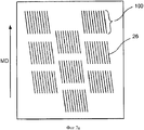
[0050] На Фиг.7а показан еще один узор расположения желобков в машинном направлении, в котором ряды желобков образуют повторяющиеся группы или раппорты 100.[0050] Fig. 7a shows another pattern of the arrangement of the grooves in the machine direction in which the rows of grooves form repeating groups or
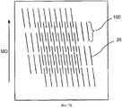
[0051] Как показано на Фиг.7а, группы 100 прерывистых желобков 26 содержат, например, десять желобков, расположенных по существу в машинном направлении, но под углом к нему. Такие желобки могут быть вырезаны при помощи так называемого «набора фрез»; обычно их вырезают по спирали. Лента содержит столько групп 100 желобков, сколько нужно для создания желаемых обезвоживающих характеристик ленты. Хотя показаны группы желобков, расположенных под углом к машинному направлению, другие виды ориентации желобков, в том числе и расположение в поперечном направлении, также попадают в область действия настоящего изобретения. Кроме того, хотя на чертеже все группы 100 желобков ориентированы одинаково, настоящее изобретение не ограничено указанным расположением; напротив, настоящее изобретение включает различные ориентации групп желобков на одной ленте. На Фиг.7b показан еще один вариант реализации настоящего изобретения, представляющий собой ленту, на которой сформированы перекрывающиеся желобки 26. Перекрывающиеся желобки 26 образуют прерывистые желобки, окружающие всю ленту в виде повторяющегося узора.[0051] As shown in FIG. 7a, groups of 100
[0052] Желобки 26, показанные на Фиг.7b, расположены под углом к машинному направлению, но могут иметь любую ориентацию, включая расположение в поперечном направлении. Располагая некоторые желобки на различном расстоянии по длине ленты, можно снизить вероятность образования следов (оттисков) от той части ленты, на которую не были нанесены желобки.[0052] The
[0053] В одном варианте реализации настоящего изобретения длина желобков 26 в машинном направлении может быть любой, вплоть до длины, приблизительно совпадающей с длиной станины.[0053] In one embodiment of the present invention, the length of the
[0054] Например, желобок 26 может иметь длину приблизительно 50 мм, а расстояние между желобками 26 в продольном направлении может приблизительно составлять 25 мм. Кроме того, желобки 26 и контактные площадки 42 могут составлять любой узор, минимизирующий вероятность гидравлического разрыва или появления отметок на бумажном листе.[0054] For example, the
[0055] На Фиг.2, 6 и 7 желобки 26 и контактные площадки 42 имеют одинаковую ширину, хотя это и не обязательно. Тем не менее, контактные площадки 42 могут быть рассмотрены как узкие колонки из отвержденной полимерной смолы, расположенные в машинном направлении на внешней поверхности 24 ленты.[0055] In FIGS. 2, 6 and 7, the
[0056] В предшествующем описании желобки 26 были рассмотрены как желобки, ориентированные в машинном, или продольном, направлении. Желобки 26 могут быть выполнены при помощи спиральной нарезки прерывистых желобков на внешней поверхности 24.[0056] In the preceding description, the
[0057] В этом случае ориентация желобков 26 может отклоняться от продольного или машинного направления на небольшой угол. Кроме того, желобки 26 могут быть выполнены при помощи спиральной нарезки двух или более соседних прерывистых желобков на внешней поверхности 24, проводимых в противоположном направлении, то есть одна из нарезок представляет собой правостороннюю спираль, а другая - левостороннюю спираль. Фрезы можно попеременно снимать с поверхности ленты так, чтобы получить короткую горизонтальную полосу контактной площадки в поперечном направлении (поперечная полоса). Поперечная полоса может быть расположена случайным образом на поверхности ленты в зависимости от длины ленты, длины желобка и длины контактной площадки.[0057] In this case, the orientation of the
[0058] В одном предпочтительном варианте реализации настоящего изобретения глубина желобков 26 может приблизительно составлять 1,4 мм, а ширина лежать в диапазоне от 0,5 до 2,0 мм. Каждый желобок 26 может быть расположен на некотором расстоянии от соседнего (ширина контактной площадки) в поперечном направлении на расстоянии от 1,0 до 2,5 мм.[0058] In one preferred embodiment of the present invention, the depth of the
[0059] Однако точное число, глубина, ширина и форма желобков 26, а также ширина контактных площадок 42 может изменяться в зависимости от конкретного применения.[0059] However, the exact number, depth, width and shape of the
[0060] Соответственно существует широкий диапазон отношений размеров желобков к размерам площадок.[0060] Accordingly, there is a wide range of ratios of groove sizes to pad sizes.
[0061] Хотя описаны желобки, проходящие в продольном или машинном направлении, настоящее изобретение не ограничено указанным расположением. Иными словами, желобки могут быть расположены в любом другом направлении, таком как поперечное направление относительно машины, или под углом θ (таким, что 0<θ<90°) к машинному направлению. В этом случае «длина» желобков 26 может быть короче ширины станины, как, например, показано на Фиг.11 и 12.[0061] Although grooves extending in the longitudinal or machine direction are described, the present invention is not limited to this arrangement. In other words, the grooves can be located in any other direction, such as the transverse direction relative to the machine, or at an angle θ (such that 0 <θ <90 °) to the machine direction. In this case, the “length” of the
[0062] Как показано на Фиг.11, желобки 26 могут быть расположены в виде ряда колонок, причем каждый из желобков может быть сформирован по существу, в поперечном направлении. Однако количество желобков в колонке и расстояние между соседними колонками в поперечном направлении на ленте 17 может меняться в зависимости от применения пресса и/или от желаемого снижения величины разбрызгивания на участке ввода в зону контакта и от эффективности обезвоживания. Такие желобки могут быть прерывистыми в поперечном направлении и их ширина (составляющая в поперечном направлении) может быть меньше длины дуговидной прижимной станины 14.[0062] As shown in FIG. 11, the
[0063] В других вариантах реализации изобретения желобки, расположенные в поперечном направлении, могут быть непрерывными, как показано на Фиг.11а, на котором желобки 26 по существу покрывают всю ширину ленты 17 в поперечном направлении. Еще в одном варианте реализации желобки 26 могут быть сформированы с образованием узора уступами, как, например, на ленте 17', изображенной на Фиг.12.[0063] In other embodiments of the invention, the grooves located in the transverse direction can be continuous, as shown in Fig. 11a, in which the
[0064] Лента для пресса станинного типа с желобками, расположенными в поперечном направлении, имеет то преимущество, что она действует наподобие крыльчатки или механизма поршневого насоса. Когда желобок 26 попадает на станину, из полотна 20 отжимается вода, которая затем попадает в желобки 26 ленты 17. Так как желобки 26 сформированы в слое водонепроницаемой смолы 34, вода не вытекает из желобков 26. По мере того как давление между прессовым валком 12 и станиной увеличивается, желобки наполняются водой, отжатой из волокнистого полотна 20. Затем продвижение ленты 17 относит воду, отжатую в желобки 26, от волокнистого полотна 20.[0064] A bed type press belt with grooves arranged in the transverse direction has the advantage that it acts like an impeller or a piston pump mechanism. When the
[0065] Так как ширина (составляющая в машинном направлении) желобков 26 меньше длины станины, вода, попадающая в желобки, не может вытечь обратно и удерживается в желобках, частично благодаря давлению, оказываемому прессовым валком 12. Такой вариант реализации может оказаться очень полезным для низкоскоростных устройств, в которых традиционно использовали простые или не содержащие желобков ленты. Однако настоящее изобретение не ограничено указанным применением и может быть использовано при различных скоростях процесса.[0065] Since the width (machine component) of the
[0066] Дополнительно, предлагаемая лента может иметь другие узоры прерывистых желобков. Например, предлагаемая лента, изображенная на Фиг.13, может содержать несколько первых желобков (таких как желобок 44) и/или несколько вторых желобков (таких как желобок 46). Полная длина и ширина каждого из желобков может быть меньше соответствующих размеров дуговидной прижимной станины 14.[0066] Additionally, the tape of the invention may have other intermittent groove patterns. For example, the tape of the invention shown in FIG. 13 may comprise several first grooves (such as groove 44) and / or several second grooves (such as groove 46). The total length and width of each of the grooves may be less than the corresponding dimensions of the
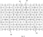
Желобки 44, 46 могут быть любой формы, в том числе помимо прочего квадратной, прямоугольной, треугольной, зигзагообразной, круглой, многоугольной; кроме того, форма указанных желобков может быть комбинацией вышеперечисленных форм. На Фиг.23 и 24 показаны варианты желобков, имеющих треугольную форму. Эти желобки могут иметь контактную площадку, разделяющую стороны структуры и расположенную между ними; однако это не обязательно, поскольку гребни соответствующих форм также могут быть соединены и тем самым могут формировать непрерывный желобок вдоль периметра указанной формы. Еще один вариант показан на Фиг.25; здесь желобки сформированы в форме шестиугольников или в форме сотовой структуры. Один или более шестиугольников указанной сотовой структуры может быть полностью заполнен смоляным покрытием. Кроме того, лента может содержать комбинацию непрерывных и прерывистых желобков, проходящих в машинном или поперечном направлении ленты. На примере Фиг.26 показаны непрерывные желобки 101 поперечного направления и непрерывные желобки 102 машинного направления, сформированные в комбинации с прерывистыми желобками 103 машинного направления и прерывистыми желобками 104 поперечного направления. Желобки любой или всех из вышеупомянутых форм, или желобки любого другого узора, предложенные в настоящем описании, могут иметь различную глубину и/или различную ширину в машинном направлении и/или в поперечном направлении ленты.The
[0067] При сравнении ленты 16 (Фиг.2) с лентой, на которую нанесены непрерывные желобки стандартного типа, причем, если на обеих лентах глубина желобков составляет 1,4 мм, а ширина - 0,8 мм, а ширина контактной площадки (расстояние между соседними желобками) составляет 2,1 мм, то величина разбрызгивания на участке ввода в зону контакта и величина разбрызгивания на участке выхода из зоны контакта могут быть измерены, и может быть построен график зависимости указанных величин от скорости машины и прилагаемого давления в зоне контакта.[0067] When comparing the tape 16 (Figure 2) with a tape on which continuous grooves of a standard type are applied, moreover, if the depth of the grooves on both tapes is 1.4 mm and the width is 0.8 mm and the width of the contact pad ( the distance between adjacent grooves) is 2.1 mm, then the spray value at the entrance to the contact zone and the spray value at the exit of the contact zone can be measured, and a graph of the dependence of these values on the machine speed and the applied pressure in the contact zone can be plotted .
[0068] Как видно из Фиг.8, при использовании ленты, на которую нанесены непрерывные желобки стандартного типа, при скорости, превышающей 300 м/мин, имеется разбрызгивание на участке ввода в зону контакта. Кроме того, по мере повышения скорости также возрастает величина разбрызгивания на участке ввода в зону контакта, а затем она снижается, как показано на чертеже. Также, по мере увеличения нагружаемого давления, возрастает величина разбрызгивания на участке ввода в зону контакта. Соответственно, существует рабочий диапазон, в котором работать с лентой, на которую нанесены непрерывные желобки стандартного типа, нежелательно.[0068] As can be seen from Fig. 8, when using a tape on which continuous grooves of a standard type are applied, at a speed exceeding 300 m / min, there is spraying at the site of entry into the contact zone. In addition, as the speed increases, the amount of spatter in the area of entry into the contact zone also increases, and then it decreases, as shown in the drawing. Also, as the loading pressure increases, the amount of spraying in the area of entry into the contact zone increases. Accordingly, there is an operating range in which it is undesirable to work with a tape on which continuous grooves of a standard type are applied.
[0069] На Фиг.9 показана скорость работы, при которой величина разбрызгивания на участке ввода в зону контакта значительно снижена в тот момент, когда лента попадает в станинный пресс. График позволяет сравнивать скорость при различных давлениях нагрузки на ленту станинного пресса, на которую нанесены непрерывные желобки.[0069] Figure 9 shows the speed at which the amount of spatter in the area of entry into the contact zone is significantly reduced at the moment the tape enters the bed press. The graph allows you to compare the speed at different load pressures on the bed press belt, on which continuous grooves are applied.
[0070] Как видно, при повышении давления нагрузки повышается скорость, необходимая для подавления разбрызгивания на участке ввода в зону контакта. Например, при давлении нагрузки, равном 600 кН/м, скорость, необходимая для подавления разбрызгивания на участке ввода в зону контакта, приблизительно равна 650 м/мин, что можно сравнить со скоростью приблизительно 810 м/мин, необходимой для подавления разбрызгивания на участке ввода в зону контакта при давлении нагрузки, равном 1200 кН/м.[0070] As can be seen, as the load pressure increases, the speed necessary to suppress spatter at the site of entry into the contact zone increases. For example, at a loading pressure of 600 kN / m, the speed required to suppress spatter at the inlet to the contact area is approximately 650 m / min, which can be compared with a speed of approximately 810 m / min necessary to suppress spatter at the inlet into the contact zone at a loading pressure of 1200 kN / m.
[0071] Как показано на Фиг.8 и 9, разбрызгивание на участке ввода в зону контакта может присутствовать при работе станинного пресса с длинной зоной контакта, в котором применяют ленту, на которую нанесены в машинном направлении непрерывные желобки стандартного типа, при скорости, превышающей 650 м/мин или менее 810 м/мин, и давлении нагрузки, находящемся в диапазоне от 600 до 1200 кН/м. Разбрызгивание на участке ввода в зону контакта снижает эффективность обезвоживания полотна и, следовательно, является нежелательной характеристикой желобчатых лент, известных ранее в настоящей области техники.[0071] As shown in Figs. 8 and 9, spraying in the contact area entry area may be present when the bed press has a long contact area, in which a tape is applied, on which machine grooves of standard type are applied at a speed exceeding 650 m / min or less than 810 m / min, and a load pressure in the range of 600 to 1200 kN / m. Spraying at the site of entry into the contact zone reduces the efficiency of dewatering the web and, therefore, is an undesirable characteristic of grooved tapes, previously known in the art.
[0072] Напротив, как видно из Фиг.10, ленты, предлагаемые в соответствии с настоящим изобретением, не вызывают или по существу не вызывают разбрызгивания на участке входа в зону контакта при давлении нагрузки, находящемся в диапазоне от 600 до 1000 кН/м, и скоростях, находящихся в диапазоне от 250 до 1000 м/мин. Соответственно, ленты с прерывистыми желобками снижают разбрызгивание на участке входа в зону контакта и, таким образом, повышают эффективность обезвоживания полотна.[0072] On the contrary, as can be seen from Figure 10, the tapes proposed in accordance with the present invention, do not cause or essentially do not cause spraying at the entrance to the contact zone at a load pressure in the range from 600 to 1000 kN / m, and speeds ranging from 250 to 1000 m / min. Accordingly, tapes with intermittent grooves reduce spraying at the entrance to the contact zone and, thus, increase the dewatering efficiency of the web.
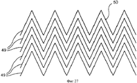
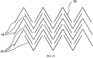
[0073] Хотя в настоящем описании рассмотрена лента, на которую нанесены прерывистые желобки, настоящее изобретение не ограничено указанной модификацией. Иными словами, на предлагаемую ленту могут быть нанесены непрерывные желобки нестандартного типа. В качестве примера можно рассмотреть Фиг.14, где на ленту 47 может быть нанесено несколько непрерывных желобков 49, каждый из которых имеет прямую часть 48, за которой следует зигзагообразная часть 50, за которой вновь следует прямая часть 48 и т.д. В другом варианте желобки 49 могут иметь только зигзагообразную часть 50 без прямых частей, как показано на Фиг.27. Эти зигзагообразные части могут быть непрерывными и прерывистыми (Фиг.28) и могут проходить в машинном и/или поперечном направлении ленты или даже могут быть сформированы под углом к машинному или поперечному направлению ленты. Длина каждой из прямых и/или зигзагообразных частей может быть меньше длины дуговидной прижимной станины 14. В другом варианте, изображенном на Фиг.15, на ленту 51 может быть нанесен один или более желобков 52, каждый из которых состоит из первой части 54, имеющей первую ширину, и второй части 56, имеющей вторую ширину, меньшую чем первая ширина. Длина второй или ограничивающей части 56 может быть меньше, чем длина дуговидной прижимной станины 14. В других вариантах реализации изобретения лента может содержать желобки синусоидальной формы или S-образной формы, как показано на Фиг.29. Следует заметить, что длина этих желобков меньше длины прижимной станины 14.[0073] Although a tape on which discontinuous grooves are applied is described herein, the present invention is not limited to this modification. In other words, continuous grooves of a non-standard type can be applied to the proposed tape. As an example, FIG. 14 can be considered, where several
[0074] Кроме того, как уже было показано, форма желобков, наносимых на ленту, предлагаемую в соответствии с настоящим изобретением, может включать различные формы поперечного сечения.[0074] Furthermore, as has already been shown, the shape of the grooves applied to the tape of the present invention may include various cross-sectional shapes.
[0075] Варианты нескольких форм поперечного сечения показаны на Фиг.16-21.[0075] Variants of several cross-sectional shapes are shown in FIGS. 16-21.
[0076] Следует понимать, что форма желобков, наносимых на ленту, предлагаемую в соответствии с настоящим изобретением, не ограничена указанными вариантами.[0076] It should be understood that the shape of the grooves applied to the tape proposed in accordance with the present invention is not limited to these options.
[0077] Еще один предпочтительный вариант реализации настоящего изобретения показан на Фиг.22. На Фиг.22 желобок 26 сформирован так, что его различные части имеют разную глубину, т.е. более глубокую часть 60 и более мелкую часть 62. Различная глубина действует по существу так же, как конечная часть прерывистых желобков, описанных выше. Иными словами, более мелкая часть 62 желобка 26 препятствует легкому вытеканию воды из более глубокой части 60 и таким образом значительно снижает склонность воды вытекать в направлении, противоположном машинному направлению, что позволяет минимизировать разбрызгивание на участке ввода в зону контакта.[0077] Another preferred embodiment of the present invention is shown in FIG. 22, a
[0078] Желобок 26, предлагаемый в соответствии с настоящим вариантом реализации изобретения, непрерывен; однако в одном предпочтительном варианте реализации длина более глубокой части 60 желобка 26 меньше длины зоны контакта станины. Это видно из сравнения кривой давления 64, показанной на Фиг.22, с глубиной желобка 26. На входе в прессовый валок 12 имеется зона 36 низкого давления, которая соответствует мелкой части 62 желобка 26. После этого давление быстро возрастает, и глубина желобка 26 также возрастает на этом участке.[0078] The
[0079] Наибольшее давление оказывается на точку, находящуюся вблизи окончания глубокой части 60 желобка 26.[0079] The greatest pressure is exerted on a point located near the end of the
[0080] Следует отметить, что в области мелких участков 62 давление резко падает. Так, в самих глубоких частях желобка 26, на которые оказывают самое высокое давление, из волокнистого полотна 20 отжимается наибольшее количество воды. Для ясности на Фиг.22 не показана прессовая ткань (позиция 18 на Фиг.1), на которой расположено волокнистое полотно 20; однако специалист в настоящей области техники легко определит, что указанная ткань обычно находится между полотном 20 и лентой 16 станинного пресса.[0080] It should be noted that in the region of the
[0081] Специалисты в данной области техники должны понимать, что существуют различные модификации настоящего изобретения, не выходящие за пределы области, защищаемой прилагаемой Формулой изобретения.[0081] Those of skill in the art should understand that there are various modifications of the present invention that do not go beyond the scope of the appended claims.
Claims (33)
основную ткань, имеющую внутреннюю и наружную поверхности;
смоляной покрывающий слой, сформированный на обращенной к листу стороне или на наружной поверхности основной ткани и по существу совпадающий с ней; и
множество непрерывных желобков, сформированных в смоляном покрывающем слое, по меньшей мере один из которых содержит только множество чередующихся частей зигзагообразного рисунка,
причем длина желобков в машинном направлении меньше длины в машинном направлении станинной части указанного станинного пресса.1. Tape to minimize spatter at the entrance to the contact area in the bed press, including:
the main fabric having an inner and outer surface;
a resin coating layer formed on the side facing the sheet or on the outer surface of the main fabric and substantially coinciding with it; and
a plurality of continuous grooves formed in a resin coating layer, at least one of which contains only a plurality of alternating parts of a zigzag pattern,
moreover, the length of the grooves in the machine direction is less than the length in the machine direction of the bed part of the specified bed press.
основную ткань, имеющую внутреннюю и наружную поверхности;
смоляной покрывающий слой, сформированный на обращенной к листу стороне или на наружной поверхности основной ткани и по существу совпадающий с ней; и
множество прерывистых желобков, сформированных в смоляном покрывающем слое и выполненных треугольными, круглыми или в виде сотовой структуры,
причем длина желобков в машинном направлении меньше длины в машинном направлении станинной части указанного станинного пресса.12. Tape to minimize spatter at the entrance to the contact zone in the bed press, including:
the main fabric having an inner and outer surface;
a resin coating layer formed on the side facing the sheet or on the outer surface of the main fabric and substantially coinciding with it; and
a plurality of intermittent grooves formed in a resin coating layer and made triangular, round or in the form of a honeycomb structure,
moreover, the length of the grooves in the machine direction is less than the length in the machine direction of the bed part of the specified bed press.
предоставление основной ткани, имеющей внутреннюю и наружную поверхности, для прессовой ленты;
нанесение полимерной смолы на обращенную к листу сторону или наружную поверхность основной ткани и
формирование в полимерной смоле множества непрерывных желобков, по меньшей мере один из которых содержит только множество чередующихся частей зигзагообразного рисунка,
причем длина желобков в машинном направлении меньше длины в машинном направлении станинной части указанного станинного пресса.17. A method of minimizing spraying at the input to the contact area in the bed press, comprising the following operations:
providing the main fabric having inner and outer surfaces for the press tape;
applying polymer resin to the side facing the sheet or the outer surface of the main fabric; and
forming in the polymer resin a plurality of continuous grooves, at least one of which contains only a plurality of alternating parts of a zigzag pattern,
moreover, the length of the grooves in the machine direction is less than the length in the machine direction of the bed part of the specified bed press.
предоставление основной ткани, имеющей внутреннюю и наружную поверхности, для прессовой ленты;
нанесение полимерной смолы на обращенную к листу сторону или наружную поверхность основной ткани и
формирование в полимерной смоле множества прерывистых желобков треугольными, круглыми или в форме сотовой структуры,
причем длина желобков в машинном направлении меньше длины в машинном направлении станинной части указанного станинного пресса.29. A method of minimizing spatter at the input to the contact area in the bed press, comprising the following operations:
providing the main fabric having inner and outer surfaces for the press tape;
applying polymer resin to the side facing the sheet or the outer surface of the main fabric; and
the formation in the polymer resin of a plurality of discontinuous grooves triangular, round or in the form of a honeycomb structure,
moreover, the length of the grooves in the machine direction is less than the length in the machine direction of the bed part of the specified bed press.
Applications Claiming Priority (3)
| Application Number | Priority Date | Filing Date | Title |
|---|---|---|---|
| US12/154,729 US8080137B2 (en) | 2003-11-18 | 2008-05-27 | Shoe press belt having a grooved surface |
| US12/154,729 | 2008-05-27 | ||
| PCT/US2009/045144 WO2009146299A1 (en) | 2008-05-27 | 2009-05-26 | Shoe press belt having a grooved surface |
Publications (2)
| Publication Number | Publication Date |
|---|---|
| RU2010148344A RU2010148344A (en) | 2012-07-10 |
| RU2530372C2 true RU2530372C2 (en) | 2014-10-10 |
Family
ID=40901826
Family Applications (1)
| Application Number | Title | Priority Date | Filing Date |
|---|---|---|---|
| RU2010148344/12A RU2530372C2 (en) | 2008-05-27 | 2009-05-26 | Belt with fluted surface for mount press |
Country Status (12)
| Country | Link |
|---|---|
| US (1) | US8080137B2 (en) |
| EP (1) | EP2313551A1 (en) |
| JP (1) | JP2011522136A (en) |
| KR (1) | KR20110017892A (en) |
| CN (2) | CN102099526B (en) |
| BR (1) | BRPI0912286A2 (en) |
| CA (1) | CA2725607A1 (en) |
| DE (1) | DE9755661T1 (en) |
| MX (1) | MX2010012810A (en) |
| RU (1) | RU2530372C2 (en) |
| TW (1) | TW201013015A (en) |
| WO (1) | WO2009146299A1 (en) |
Families Citing this family (3)
| Publication number | Priority date | Publication date | Assignee | Title |
|---|---|---|---|---|
| EP2910679B1 (en) * | 2011-12-07 | 2017-05-17 | Valmet Aktiebolag | An extended nip roll for a papermaking machine and a method of producing tissue paper |
| US10536232B2 (en) | 2015-06-29 | 2020-01-14 | Visteon Global Technologies, Inc. | Integrating audio content with additional digital content |
| EP3739114B1 (en) * | 2019-05-14 | 2021-03-10 | BillerudKorsnäs AB | Efficient production of a containerboard to be used as fluting |
Citations (3)
| Publication number | Priority date | Publication date | Assignee | Title |
|---|---|---|---|---|
| WO2004094720A1 (en) * | 2003-04-17 | 2004-11-04 | Albany International Corp. | Grooved shoe press belt with conical rebates |
| WO2005049917A1 (en) * | 2003-11-18 | 2005-06-02 | Albany International Corp. | Shoe press belt having a grooved surface |
| RU2005120644A (en) * | 2002-12-31 | 2006-02-10 | Олбэни Интернэшнл Корп. (Us) | METHOD FOR MANUFACTURING STRUCTURES OF RESIN-INFINED INFINITE TAPES USED IN PAPER MANUFACTURE AND IN PROCESSING PAPER, AND ALSO TAPE |
Family Cites Families (32)
| Publication number | Priority date | Publication date | Assignee | Title |
|---|---|---|---|---|
| US4287021A (en) * | 1979-08-27 | 1981-09-01 | Beloit Corporation | Extended nip press |
| FR2494318B1 (en) | 1980-11-14 | 1986-10-10 | Feutres Papeteries Tissus Indl | BAND CONSISTING OF SPIRALS |
| US5238537A (en) | 1981-09-15 | 1993-08-24 | Dutt William H | Extended nip press belt having an interwoven base fabric and an impervious impregnant |
| FI75620C (en) | 1982-04-01 | 1988-07-11 | Tampella Oy Ab | LAONGZONSPRESS FOER EN PAPPERSMASKIN. |
| US4427734A (en) | 1982-04-19 | 1984-01-24 | Albany International Corp. | Wet press felt for papermaking machines |
| US4643916A (en) | 1982-10-01 | 1987-02-17 | Ichikawa Woolen Textile Co., Ltd. | Method for manufacturing a pressure belt for use with extended nip press in paper making machine |
| JPS5954598U (en) | 1982-10-01 | 1984-04-10 | 市川毛織株式会社 | Pressure belt for wide nip press of paper machine |
| JPS63162726A (en) | 1986-12-26 | 1988-07-06 | Ube Ind Ltd | Hybrid fiber-reinforced composite |
| US4946731A (en) | 1989-09-28 | 1990-08-07 | Albany International Corp. | Construction for an extended nip press belt |
| SE468602B (en) | 1990-12-17 | 1993-02-15 | Albany Int Corp | PRESS FILT AND WAY TO MANUFACTURE THEM |
| US5208087A (en) | 1991-10-08 | 1993-05-04 | Albany International Corp. | Spiral construction for a long nip press belt |
| DE4202731C2 (en) | 1992-01-31 | 1997-04-17 | Voith Gmbh J M | Press jacket for a shoe press |
| DE4401580A1 (en) | 1994-01-20 | 1994-06-01 | Voith Gmbh J M | Paper making press section - has reduced stiffness at edges of units forming press gap to reduce wear at edges |
| DE4411621A1 (en) | 1994-04-02 | 1995-10-05 | Voith Sulzer Papiermasch Gmbh | Long-life abrasion-proof pressing cover to drain water from paper web |
| JP3053334B2 (en) | 1994-06-22 | 2000-06-19 | 市川毛織株式会社 | Shoe press belt |
| DE4445472C2 (en) | 1994-12-20 | 2000-05-11 | Voith Sulzer Papiermasch Gmbh | Press jacket for a press device for dewatering a paper web |
| US5792323A (en) | 1995-09-07 | 1998-08-11 | Albany International Corp. | Spiral base structres for long nip paper machine press belts |
| DE19626420A1 (en) | 1996-07-01 | 1998-01-08 | Voith Sulzer Papiermasch Gmbh | Pressing device |
| DE19637477A1 (en) | 1996-09-13 | 1998-03-19 | Voith Sulzer Papiermasch Gmbh | Press jacket for a press device |
| DE19722638A1 (en) | 1997-05-30 | 1998-12-03 | Voith Sulzer Papiermasch Gmbh | Press jacket for a press device |
| JPH1112975A (en) | 1997-06-21 | 1999-01-19 | Ichikawa Woolen Textile Co Ltd | Belt for shoe press |
| DE19752752B4 (en) | 1997-11-28 | 2007-01-25 | Bayerische Motoren Werke Ag | Transmission control device with an electronic control device for a motor vehicle with an automatic transmission |
| DE19752725A1 (en) | 1997-11-28 | 1999-06-02 | Voith Sulzer Papiertech Patent | Pressure application mantle on roller |
| SE511736C2 (en) | 1998-03-20 | 1999-11-15 | Nordiskafilt Ab Albany | Embossing ribbon for a paper machine |
| US6428874B1 (en) | 2000-11-03 | 2002-08-06 | Albany International Corp. | Grooved long nip shoe press belt |
| FI20010721A (en) | 2001-04-06 | 2002-10-07 | Metso Paper Inc | Tape for a press roll and a press concept |
| JP3614793B2 (en) | 2001-04-27 | 2005-01-26 | ヤマウチ株式会社 | Shoe press belt |
| JP3614830B2 (en) | 2002-04-11 | 2005-01-26 | ヤマウチ株式会社 | Shoe press belt and shoe press apparatus using the same |
| US7005044B2 (en) * | 2002-12-31 | 2006-02-28 | Albany International Corp. | Method of fabricating a belt and a belt used to make bulk tissue and towel, and nonwoven articles and fabrics |
| US6854301B1 (en) | 2004-04-13 | 2005-02-15 | Albany International Corp. | Extended nip press for the leather industry |
| JP4477025B2 (en) | 2007-03-12 | 2010-06-09 | イチカワ株式会社 | Shoe press belt for papermaking |
| WO2009066700A1 (en) * | 2007-11-20 | 2009-05-28 | Ichikawa Co., Ltd. | Paper making shoe press belt |
-
2008
- 2008-05-27 US US12/154,729 patent/US8080137B2/en active Active
-
2009
- 2009-05-26 KR KR1020107029275A patent/KR20110017892A/en not_active Application Discontinuation
- 2009-05-26 TW TW098117451A patent/TW201013015A/en unknown
- 2009-05-26 EP EP09755661A patent/EP2313551A1/en not_active Withdrawn
- 2009-05-26 JP JP2011511752A patent/JP2011522136A/en active Pending
- 2009-05-26 RU RU2010148344/12A patent/RU2530372C2/en active
- 2009-05-26 BR BRPI0912286A patent/BRPI0912286A2/en not_active Application Discontinuation
- 2009-05-26 CN CN200980127098.4A patent/CN102099526B/en active Active
- 2009-05-26 WO PCT/US2009/045144 patent/WO2009146299A1/en active Application Filing
- 2009-05-26 MX MX2010012810A patent/MX2010012810A/en active IP Right Grant
- 2009-05-26 CN CN201410269776.3A patent/CN104109981A/en active Pending
- 2009-05-26 DE DE9755661T patent/DE9755661T1/en active Pending
- 2009-05-26 CA CA2725607A patent/CA2725607A1/en not_active Abandoned
Patent Citations (3)
| Publication number | Priority date | Publication date | Assignee | Title |
|---|---|---|---|---|
| RU2005120644A (en) * | 2002-12-31 | 2006-02-10 | Олбэни Интернэшнл Корп. (Us) | METHOD FOR MANUFACTURING STRUCTURES OF RESIN-INFINED INFINITE TAPES USED IN PAPER MANUFACTURE AND IN PROCESSING PAPER, AND ALSO TAPE |
| WO2004094720A1 (en) * | 2003-04-17 | 2004-11-04 | Albany International Corp. | Grooved shoe press belt with conical rebates |
| WO2005049917A1 (en) * | 2003-11-18 | 2005-06-02 | Albany International Corp. | Shoe press belt having a grooved surface |
Also Published As
| Publication number | Publication date |
|---|---|
| BRPI0912286A2 (en) | 2015-10-20 |
| KR20110017892A (en) | 2011-02-22 |
| EP2313551A1 (en) | 2011-04-27 |
| TW201013015A (en) | 2010-04-01 |
| JP2011522136A (en) | 2011-07-28 |
| RU2010148344A (en) | 2012-07-10 |
| CN104109981A (en) | 2014-10-22 |
| US20090029051A1 (en) | 2009-01-29 |
| CA2725607A1 (en) | 2009-12-03 |
| CN102099526B (en) | 2014-07-16 |
| WO2009146299A1 (en) | 2009-12-03 |
| CN102099526A (en) | 2011-06-15 |
| MX2010012810A (en) | 2011-02-23 |
| US8080137B2 (en) | 2011-12-20 |
| DE9755661T1 (en) | 2011-09-29 |
Similar Documents
| Publication | Publication Date | Title |
|---|---|---|
| CN1119453C (en) | Strengthening extended diaphragm base for paper making | |
| US6428874B1 (en) | Grooved long nip shoe press belt | |
| RU2406792C2 (en) | Band with chute surface used in press with plate | |
| RU2530372C2 (en) | Belt with fluted surface for mount press | |
| RU2360057C2 (en) | Belt used in paper industry with surface structure that contains porous membrane | |
| RU2384663C2 (en) | Endless tape with controlled value of channels | |
| RU2338023C2 (en) | Band for shoe press with grooves and conic flutes | |
| RU2363795C2 (en) | Belt or roller with relief coating and method of their manufacturing |