RU2529762C2 - System for controlling variable geometry devices in turbo machines and turbo machine having said system - Google Patents
System for controlling variable geometry devices in turbo machines and turbo machine having said system Download PDFInfo
- Publication number
- RU2529762C2 RU2529762C2 RU2011117534/06A RU2011117534A RU2529762C2 RU 2529762 C2 RU2529762 C2 RU 2529762C2 RU 2011117534/06 A RU2011117534/06 A RU 2011117534/06A RU 2011117534 A RU2011117534 A RU 2011117534A RU 2529762 C2 RU2529762 C2 RU 2529762C2
- Authority
- RU
- Russia
- Prior art keywords
- control
- drive mechanism
- devices
- variable geometry
- range
- Prior art date
Links
- 230000007246 mechanism Effects 0.000 claims abstract description 87
- 238000005070 sampling Methods 0.000 claims description 26
- 238000009434 installation Methods 0.000 claims description 25
- 230000033001 locomotion Effects 0.000 claims description 25
- 230000003321 amplification Effects 0.000 claims description 10
- 238000003199 nucleic acid amplification method Methods 0.000 claims description 10
- 230000000694 effects Effects 0.000 abstract description 3
- 239000000126 substance Substances 0.000 abstract 1
- 230000008859 change Effects 0.000 description 12
- 230000001276 controlling effect Effects 0.000 description 9
- 230000009471 action Effects 0.000 description 7
- 238000002485 combustion reaction Methods 0.000 description 7
- 230000000875 corresponding effect Effects 0.000 description 7
- 239000000446 fuel Substances 0.000 description 6
- 238000003032 molecular docking Methods 0.000 description 5
- 230000005540 biological transmission Effects 0.000 description 4
- 210000000056 organ Anatomy 0.000 description 4
- 230000003014 reinforcing effect Effects 0.000 description 3
- 230000008901 benefit Effects 0.000 description 2
- 230000006835 compression Effects 0.000 description 2
- 238000007906 compression Methods 0.000 description 2
- 238000000605 extraction Methods 0.000 description 2
- XLYOFNOQVPJJNP-UHFFFAOYSA-N water Substances O XLYOFNOQVPJJNP-UHFFFAOYSA-N 0.000 description 2
- 230000001154 acute effect Effects 0.000 description 1
- 238000006243 chemical reaction Methods 0.000 description 1
- 230000002596 correlated effect Effects 0.000 description 1
- 230000009977 dual effect Effects 0.000 description 1
- 239000007789 gas Substances 0.000 description 1
- 239000000203 mixture Substances 0.000 description 1
- 239000007800 oxidant agent Substances 0.000 description 1
- 230000001105 regulatory effect Effects 0.000 description 1
- 230000000717 retained effect Effects 0.000 description 1
- 230000001360 synchronised effect Effects 0.000 description 1
Images


Classifications
-
- F—MECHANICAL ENGINEERING; LIGHTING; HEATING; WEAPONS; BLASTING
- F01—MACHINES OR ENGINES IN GENERAL; ENGINE PLANTS IN GENERAL; STEAM ENGINES
- F01D—NON-POSITIVE DISPLACEMENT MACHINES OR ENGINES, e.g. STEAM TURBINES
- F01D17/00—Regulating or controlling by varying flow
- F01D17/10—Final actuators
- F01D17/12—Final actuators arranged in stator parts
- F01D17/14—Final actuators arranged in stator parts varying effective cross-sectional area of nozzles or guide conduits
- F01D17/16—Final actuators arranged in stator parts varying effective cross-sectional area of nozzles or guide conduits by means of nozzle vanes
-
- F—MECHANICAL ENGINEERING; LIGHTING; HEATING; WEAPONS; BLASTING
- F01—MACHINES OR ENGINES IN GENERAL; ENGINE PLANTS IN GENERAL; STEAM ENGINES
- F01D—NON-POSITIVE DISPLACEMENT MACHINES OR ENGINES, e.g. STEAM TURBINES
- F01D17/00—Regulating or controlling by varying flow
- F01D17/20—Devices dealing with sensing elements or final actuators or transmitting means between them, e.g. power-assisted
-
- F—MECHANICAL ENGINEERING; LIGHTING; HEATING; WEAPONS; BLASTING
- F02—COMBUSTION ENGINES; HOT-GAS OR COMBUSTION-PRODUCT ENGINE PLANTS
- F02C—GAS-TURBINE PLANTS; AIR INTAKES FOR JET-PROPULSION PLANTS; CONTROLLING FUEL SUPPLY IN AIR-BREATHING JET-PROPULSION PLANTS
- F02C6/00—Plural gas-turbine plants; Combinations of gas-turbine plants with other apparatus; Adaptations of gas-turbine plants for special use
- F02C6/04—Gas-turbine plants providing heated or pressurised working fluid for other apparatus, e.g. without mechanical power output
- F02C6/06—Gas-turbine plants providing heated or pressurised working fluid for other apparatus, e.g. without mechanical power output providing compressed gas
- F02C6/08—Gas-turbine plants providing heated or pressurised working fluid for other apparatus, e.g. without mechanical power output providing compressed gas the gas being bled from the gas-turbine compressor
-
- F—MECHANICAL ENGINEERING; LIGHTING; HEATING; WEAPONS; BLASTING
- F02—COMBUSTION ENGINES; HOT-GAS OR COMBUSTION-PRODUCT ENGINE PLANTS
- F02C—GAS-TURBINE PLANTS; AIR INTAKES FOR JET-PROPULSION PLANTS; CONTROLLING FUEL SUPPLY IN AIR-BREATHING JET-PROPULSION PLANTS
- F02C9/00—Controlling gas-turbine plants; Controlling fuel supply in air- breathing jet-propulsion plants
- F02C9/16—Control of working fluid flow
- F02C9/18—Control of working fluid flow by bleeding, bypassing or acting on variable working fluid interconnections between turbines or compressors or their stages
-
- F—MECHANICAL ENGINEERING; LIGHTING; HEATING; WEAPONS; BLASTING
- F02—COMBUSTION ENGINES; HOT-GAS OR COMBUSTION-PRODUCT ENGINE PLANTS
- F02C—GAS-TURBINE PLANTS; AIR INTAKES FOR JET-PROPULSION PLANTS; CONTROLLING FUEL SUPPLY IN AIR-BREATHING JET-PROPULSION PLANTS
- F02C9/00—Controlling gas-turbine plants; Controlling fuel supply in air- breathing jet-propulsion plants
- F02C9/16—Control of working fluid flow
- F02C9/20—Control of working fluid flow by throttling; by adjusting vanes
- F02C9/22—Control of working fluid flow by throttling; by adjusting vanes by adjusting turbine vanes
-
- F—MECHANICAL ENGINEERING; LIGHTING; HEATING; WEAPONS; BLASTING
- F04—POSITIVE - DISPLACEMENT MACHINES FOR LIQUIDS; PUMPS FOR LIQUIDS OR ELASTIC FLUIDS
- F04D—NON-POSITIVE-DISPLACEMENT PUMPS
- F04D27/00—Control, e.g. regulation, of pumps, pumping installations or pumping systems specially adapted for elastic fluids
- F04D27/02—Surge control
- F04D27/0207—Surge control by bleeding, bypassing or recycling fluids
- F04D27/023—Details or means for fluid extraction
-
- F—MECHANICAL ENGINEERING; LIGHTING; HEATING; WEAPONS; BLASTING
- F04—POSITIVE - DISPLACEMENT MACHINES FOR LIQUIDS; PUMPS FOR LIQUIDS OR ELASTIC FLUIDS
- F04D—NON-POSITIVE-DISPLACEMENT PUMPS
- F04D29/00—Details, component parts, or accessories
- F04D29/40—Casings; Connections of working fluid
- F04D29/52—Casings; Connections of working fluid for axial pumps
- F04D29/54—Fluid-guiding means, e.g. diffusers
- F04D29/56—Fluid-guiding means, e.g. diffusers adjustable
- F04D29/563—Fluid-guiding means, e.g. diffusers adjustable specially adapted for elastic fluid pumps
-
- F—MECHANICAL ENGINEERING; LIGHTING; HEATING; WEAPONS; BLASTING
- F05—INDEXING SCHEMES RELATING TO ENGINES OR PUMPS IN VARIOUS SUBCLASSES OF CLASSES F01-F04
- F05D—INDEXING SCHEME FOR ASPECTS RELATING TO NON-POSITIVE-DISPLACEMENT MACHINES OR ENGINES, GAS-TURBINES OR JET-PROPULSION PLANTS
- F05D2270/00—Control
- F05D2270/50—Control logic embodiments
- F05D2270/58—Control logic embodiments by mechanical means, e.g. levers, gears or cams
-
- Y—GENERAL TAGGING OF NEW TECHNOLOGICAL DEVELOPMENTS; GENERAL TAGGING OF CROSS-SECTIONAL TECHNOLOGIES SPANNING OVER SEVERAL SECTIONS OF THE IPC; TECHNICAL SUBJECTS COVERED BY FORMER USPC CROSS-REFERENCE ART COLLECTIONS [XRACs] AND DIGESTS
- Y02—TECHNOLOGIES OR APPLICATIONS FOR MITIGATION OR ADAPTATION AGAINST CLIMATE CHANGE
- Y02T—CLIMATE CHANGE MITIGATION TECHNOLOGIES RELATED TO TRANSPORTATION
- Y02T50/00—Aeronautics or air transport
- Y02T50/60—Efficient propulsion technologies, e.g. for aircraft
Landscapes
- Engineering & Computer Science (AREA)
- Mechanical Engineering (AREA)
- General Engineering & Computer Science (AREA)
- Chemical & Material Sciences (AREA)
- Combustion & Propulsion (AREA)
- Physics & Mathematics (AREA)
- Fluid Mechanics (AREA)
- Life Sciences & Earth Sciences (AREA)
- Sustainable Development (AREA)
- Structures Of Non-Positive Displacement Pumps (AREA)
- Control Of Turbines (AREA)
Abstract
Description
Настоящее изобретение в целом относится к области управления устройствами с изменяемой геометрией турбомашины. В частности, изобретение относится к оптимизации управления множеством устройств турбомашины.The present invention generally relates to the field of control of variable geometry turbomachine devices. In particular, the invention relates to optimizing control of a plurality of turbomachine devices.
Под термином «устройство с изменяемой геометрией» здесь понимается устройство, содержащее орган управления, размеры, форма, расположение и/или скорость которого способны по отдельности или в совокупности изменяться, в зависимости от возникающих событий или режимов работы турбомашины, с целью воздействия на работу турбомашины. Примерами изменяемых геометрий в подобных устройствах являются положения заслонок отбора воздуха из компрессора, радиальные зазоры лопаток турбины, скорости вращения топливного насоса и т.д.The term "device with variable geometry" here means a device containing a control, the size, shape, location and / or speed of which can individually or collectively change, depending on the events or modes of operation of the turbomachine, with the aim of influencing the operation of the turbomachine . Examples of variable geometries in such devices are the positions of the air intake shutters from the compressor, the radial clearances of the turbine blades, the speed of the fuel pump, etc.
Под термином «корпус», в том смысле, в котором он применяется в данном описании, здесь понимается узел турбомашины, содержащий в качестве своих основных органов компрессор и турбину, собранные на одной оси. Частным случаем корпусов является форсажная камера, в которой компрессор состоит только из дозвукового реактивного сопла и используется в прямоточных воздушно-реактивных двигателях. Типичными примерами отдельных корпусов турбомашины являются корпусы низкого и высокого давления турбореактивного двигателя.The term "housing", in the sense in which it is used in this description, is understood here as a turbomachine assembly containing, as its main organs, a compressor and a turbine assembled on one axis. A special case of housings is the afterburner, in which the compressor consists only of a subsonic jet nozzle and is used in ramjet engines. Typical examples of individual turbomachine housings are turbojet low and high pressure housings.
Как правило, корпусы турбомашины имеют конструкцию, обеспечивающую возможность их работы независимо друг от друга (см., например, патент США №4403912). Скорости их вращения не зависят друг от друга, причем даже в тех случаях, когда они могут быть связаны друг с другом или коррелированны друг относительно друга в некоторых режимах работы.Typically, turbomachine bodies have a design that allows them to operate independently of each other (see, for example, US Pat. No. 4,403,912). The speeds of their rotation are independent of each other, and even in those cases when they can be connected with each other or correlated relative to each other in some operating modes.
Именно по причине этой независимости друг относительно друга различных корпусов одной турбомашины, обычно для управления устройствами с изменяемой геометрией, входящими в состав различных корпусов, предусматривают отдельные системы управления. По этой причине управление двумя устройствами с изменяемой геометрией двух отдельных корпусов требует, таким образом, как правило, двух контуров управления, двух приводных механизмов, двух источников питания и т.д.It is precisely because of this independence of the various casings of one turbomachine relative to each other, usually for controlling devices with variable geometry that are part of various casings, separate control systems are provided. For this reason, the control of two devices with variable geometry of two separate housings thus requires, as a rule, two control loops, two drive mechanisms, two power supplies, etc.
Это приводит к тому, что масса, стоимость и габаритные размеры подобной системы управления оказываются относительно высокими. А это может представлять собой, в частности, проблему в случае турбомашин, применяемых на небольших самолетах, для которых подобная проблема является особенно острой.This leads to the fact that the mass, cost and overall dimensions of such a control system are relatively high. And this can be, in particular, a problem in the case of turbomachines used on small aircraft, for which this problem is especially acute.
Таким образом, первой задачей изобретения является создание системы управления для управления, по меньшей мере, двумя устройствами с изменяемой геометрией в турбомашине, имеющей корпус высокого давления и корпус низкого давления, причем система содержит приводной механизм, который воздействует на два устройства из указанных, по меньшей мере, двух устройств с изменяемой геометрией, при этом одно из указанных двух устройств с изменяемой геометрией является лопаточным устройством, имеющим, по меньшей мере, одну ступень лопаток статора с переменным углом установки, а другое из указанных двух устройств с изменяемой геометрией является клапанным устройством, представляющим собой клапан отбора воздуха для корпуса турбомашины, причем лопаточное устройство является частью корпуса высокого давления, а клапанное устройство является частью корпуса низкого давления, отличающаяся тем, что она выполнена с возможностью управления постепенным открытием ступени лопаток и постепенным закрытием клапана отбора воздуха по мере возрастания значения параметра управления приводным механизмом; причем такая система управления позволяет решить, по меньшей мере, частично указанные выше проблемы ее массы, стоимости и габаритных размеров.Thus, the first objective of the invention is to provide a control system for controlling at least two variable geometry devices in a turbomachine having a high pressure housing and a low pressure housing, the system comprising a drive mechanism that acts on two of said at least at least two devices with variable geometry, while one of these two devices with variable geometry is a blade device having at least one stage of the stator vanes with a mounting angle, and the other of the two variable geometry devices is a valve device, which is an air bleed valve for the turbomachine body, the blade device being part of the high pressure housing, and the valve device being part of the low pressure housing, characterized in that it is made with the ability to control the gradual opening of the blade stage and the gradual closure of the air bleed valve as the value of the control parameter of the drive fur increases Lowland; moreover, such a control system allows to solve, at least partially, the above problems of its mass, cost and overall dimensions.
Решение этой задачи обеспечивается за счет того, что принцип работы системы управления предусматривает управление постепенным открытием ступени лопаток и постепенным закрытием клапана отбора воздуха, по мере возрастания параметра управления приводного механизма.The solution to this problem is provided due to the fact that the principle of operation of the control system provides for the control of the gradual opening of the stage of the blades and the gradual closing of the air sampling valve, as the control parameter of the drive mechanism increases.
Согласно одному из вариантов реализации изобретения, система управления способна управлять тремя и даже четырьмя устройствами с изменяемой геометрией, посредством одного единственного приводного механизма.According to one embodiment of the invention, the control system is capable of controlling three or even four variable geometry devices by means of a single drive mechanism.
Согласно одному из вариантов реализации изобретения одно устройство с изменяемой геометрией является общим для нескольких корпусов турбомашины, в частности, для двух корпусов. Путем использования одного единственного приводного механизма, управляющего несколькими (по меньшей мере, двумя) устройствами с изменяемой геометрией, система управления позволяет уменьшить количество деталей турбомашины и обеспечить, таким образом, решение задачи изобретения. Проблем, связанных с весом, объемом, стоимостью второй системы управления вторым устройством с изменяемой геометрией, таким образом, удается, по меньшей мере, в значительной степени, избежать.According to one embodiment of the invention, one variable geometry device is common to several turbomachine bodies, in particular two bodies. By using one single drive mechanism that controls several (at least two) devices with variable geometry, the control system allows you to reduce the number of parts of the turbomachine and thus provide a solution to the problem of the invention. The problems associated with the weight, volume, cost of the second control system of the second variable geometry device can thus be avoided at least to a large extent.
Изобретение может быть в частности применено в двухкорпусной турбомашине, то есть в турбомашине, располагающей корпусом высокого давления и корпусом низкого давления. Одна или несколько ступеней лопаток с переменным углом установки входят обычно в состав корпуса высокого давления. В этом случае, первое устройство, управляемое системой управления, может входить в состав корпуса низкого давления турбомашины, а второе управляемое устройство, которое включает в себя одну или несколько ступеней лопаток с переменным углом установки, входит в состав корпуса высокого давления.The invention can in particular be applied in a twin-cylinder turbomachine, that is, in a turbomachine having a high-pressure housing and a low-pressure housing. One or more stages of blades with a variable installation angle are usually part of the high-pressure housing. In this case, the first device controlled by the control system may be part of the low pressure housing of the turbomachine, and the second controlled device, which includes one or more stages of blades with a variable installation angle, is included in the high pressure housing.
Ступени лопаток с переменным углом установки, входящие в состав корпуса высокого давления турбомашины, поддаются, в частности, управлению совместно с устройством корпуса низкого давления, в том случае, когда они расположены по периферии (и несколько до) корпуса высокого давления. Таким образом, они располагаются вблизи корпуса низкого давления. Указанная близость способствует реализации системы управления, общей как для ступеней лопаток, так и для устройств, имеющих переменную геометрию корпуса низкого давления.The stages of the blades with a variable installation angle, which are part of the high-pressure housing of the turbomachine, can be controlled, in particular, together with the low-pressure housing device, in the case when they are located on the periphery (and somewhat up to) of the high-pressure housing. Thus, they are located near the low pressure housing. This proximity contributes to the implementation of a control system common to both the blade stages and devices having variable geometry of the low-pressure housing.
Согласно одному из вариантов реализации изобретения ступень лопаток во втором устройстве состоит из множества лопаток, каждая из которых установлена, с возможностью поворота, на корпусе компрессора турбомашины, а также из кольца управления, окружающего корпус компрессора и связанного с каждой из лопаток посредством рычагов, при этом приводной механизм способен приводить во вращение кольцо управления ступенью посредством приводного органа, установленного, с возможностью вращения, на корпусе компрессора.According to one embodiment of the invention, the blade stage in the second device consists of a plurality of blades, each of which is mounted, rotatably, on the compressor housing of the turbomachine, as well as a control ring surrounding the compressor housing and connected to each of the blades by means of levers, while the drive mechanism is capable of driving the step control ring into rotation by means of a drive member mounted rotatably on the compressor housing.
Согласно варианту реализации изобретения устройство с изменяемой геометрией, которое представляет собой заслонку отбора воздуха турбомашины или содержит, по меньшей мере, одну заслонку отбора воздуха турбомашины, может представлять собой заслонку или даже набор разгрузочных заслонок или заслонок отбора воздуха.According to an embodiment of the invention, the variable geometry device, which is a turbomachine air bleed flap or comprises at least one turbomachine air bleed flap, may be a flap or even a set of unloading flaps or air bleed flaps.
Согласно другим различным вариантам реализации изобретения устройство с изменяемой геометрией, которое представляет собой или содержит, по меньшей мере, одну заслонку отбора воздуха, представляет собой или содержит один из следующих элементов или один элемент одного из следующих устройств:According to various other embodiments of the invention, the variable geometry device, which is or comprises at least one air sampling flap, is or comprises one of the following elements or one element of one of the following devices:
- одну бустерную заслонку отбора воздуха (VBV);- one booster air intake flap (VBV);
- одну заслонку отбора воздуха из компрессора высокого давления с пропорциональным открытием (SBV);- one air intake valve from a high-pressure compressor with proportional opening (SBV);
- одну заслонку отбора воздуха из компрессора высокого давления, работающую в режиме "полностью открыто или закрыто" (HBV);- one damper for air extraction from the high-pressure compressor, operating in the "fully open or closed" (HBV) mode;
- одну заслонку регулирования расхода воздуха, участвующую в управлении зазором в турбине низкого давления (LPTACC) или в турбине высокого давления (НРТАСС).- one air flow control damper participating in the clearance control in a low pressure turbine (LPTACC) or in a high pressure turbine (НРТАСС).
Кроме того, система управления согласно изобретению может содержать, в частности, следующие различные усовершенствования.In addition, the control system according to the invention may include, in particular, the following various improvements.
Согласно одному из вариантов реализации изобретения приводной механизм системы управления содержит подвижный орган управления, перемещения которого сопровождаются подачей команды двум устройствам. В качестве органа управления может применяться, например, рычаг гидроцилиндра.According to one embodiment of the invention, the drive mechanism of the control system comprises a movable control element, the movements of which are accompanied by the issuance of a command to two devices. As a control element, for example, a hydraulic cylinder lever can be used.
В одном варианте этого варианта реализации изобретения, приводной механизм предназначен для воздействия на первое из этих устройств за счет изменения параметра в диапазоне управления первым устройством, вне пределов которого он не в состоянии воздействовать на первое устройство, при этом приводной механизм предназначен для воздействия на второе из этих устройств за счет изменения того же параметра в диапазоне управления вторым устройством, вне пределов которого он не в состоянии воздействовать на второе устройство, причем, по меньшей мере, часть диапазона управления первым устройством находится вне пределов диапазона управления вторым устройством.In one embodiment of this embodiment, the drive mechanism is designed to act on the first of these devices by changing a parameter in the control range of the first device, outside of which it is not able to act on the first device, while the drive mechanism is designed to act on the second of of these devices by changing the same parameter in the control range of the second device, outside of which it is not able to act on the second device, and, at least at least part of the control range of the first device is outside the control range of the second device.
Указанным выше параметром приводного механизма является, как правило, параметр положения органа управления приводным механизмом. Например, в качестве этого параметра может рассматриваться положение конца рычага гидроцилиндра. Изменять этот параметр означает на самом деле перемещать эквивалентным образом конец гидроцилиндра или изменять положение воздействующего конца приводного механизма.The above-mentioned parameter of the drive mechanism is, as a rule, the position parameter of the control element of the drive mechanism. For example, the position of the end of the hydraulic cylinder lever can be considered as this parameter. Changing this parameter means actually moving the end of the hydraulic cylinder in an equivalent way or changing the position of the acting end of the drive mechanism.
В этой системе управления, управление с помощью одного единственного приводного механизма двумя устройствами с изменяемой геометрией облегчается тем обстоятельством, что диапазоны управления обоими устройствами не соответствуют друг другу ввиду того, что диапазон управления одним из них (первое устройство) содержит участок, не входящий в состав диапазона другого (второго устройства).In this control system, the control of two devices with variable geometry using one single drive mechanism is facilitated by the fact that the control ranges of both devices do not correspond to each other due to the fact that the control range of one of them (the first device) contains a section that is not part of range of another (second device).
Работа системы управления обычно предусматривается таким образом, чтобы изменений параметра приводного механизма внутри зоны, ограниченной двумя границами диапазона управления каждого из устройств, было достаточно для их приведения в действие с достаточной амплитудой в пределах этого диапазона.The operation of the control system is usually provided in such a way that changes in the parameter of the drive mechanism within the zone bounded by two boundaries of the control range of each device are sufficient to drive them with a sufficient amplitude within this range.
Кроме того, в том случае, когда величина параметра управления меняется в интервале, выходящем за пределы диапазона управления устройствами, последнее не приводится в действие посредством приводного механизма. Подобный интервал значений параметра приводного механизма, внутри которого никакое воздействие по существу не прикладывается к рассматриваемому устройству, представляет собой зону «мертвого хода». В этом диапазоне приводной механизм, при любых изменениях значений параметра, не воздействует (или воздействует только незначительным образом) на рассматриваемое устройство.In addition, in the case when the value of the control parameter varies in an interval outside the range of the device control, the latter is not driven by the drive mechanism. A similar interval of values of the parameter of the drive mechanism, inside which no effect is essentially applied to the device in question, represents a zone of "backlash". In this range, the drive mechanism, with any changes in the parameter values, does not affect (or only slightly affects) the device in question.
Трудность управления при использовании этой системы управления заключается в том, что каждое воздействие на приводной механизм передается или может передаваться (в зависимости от того, находятся ли устройства внутри или за пределами своих диапазонов приведения их в действие) одному или другому устройству.The difficulty of control when using this control system is that each effect on the drive mechanism is transmitted or can be transmitted (depending on whether the devices are inside or outside their ranges of actuation of them) to one or another device.
В частности, в том случае, когда изменение значения параметра управления производят внутри диапазона, являющегося общим для диапазонов управления обоими приводными механизмами, воздействуют одновременно как на одно, так и на другое устройство.In particular, in the case when the control parameter value is changed within a range that is common to the control ranges of both drive mechanisms, they act simultaneously on one and the other device.
Например, изменение значения параметра приводного механизма внутри диапазона управления первым устройством, когда это изменение находится также внутри диапазона управления другим устройством, приводит к одновременной передаче новой команды сразу двум устройствам ввиду того, что обе команды обусловлены изменением одного и того же параметра, например, параметра управления.For example, a change in the value of a parameter of the drive mechanism within the control range of the first device, when this change is also within the control range of another device, leads to the simultaneous transmission of a new command to two devices at once, because both commands are caused by a change in the same parameter, for example, a parameter management.
Эту трудность использования системы управления согласно изобретению можно, тем не менее, рассматривать в качестве допустимой, а иногда и не заслуживающей внимания и даже несуществующей, в том случае, когда взаимное перекрытие диапазонов управления обоими устройствами достаточно мало, и/или когда амплитуда изменений управления, по меньшей мере, одним устройством может оставаться низкой или ограниченной даже тогда, когда параметр управления проходит по всему диапазону управления другого устройства.This difficulty of using the control system according to the invention can nevertheless be regarded as permissible, and sometimes not worthy of attention and even nonexistent, in the case when the mutual overlap of the control ranges of both devices is sufficiently small, and / or when the amplitude of the control changes at least one device may remain low or limited even when the control parameter extends over the entire control range of another device.
Поэтому, несмотря на трудность использования системы управления согласно изобретению, все равно преимущество, связанное с возможностью одновременного управления в одной турбомашине двумя устройствами с изменяемой геометрией, представляет определенный интерес, с учетом возможности не заниматься в этом случае проблемами веса, габаритов и стоимости двойной системы управления.Therefore, despite the difficulty of using the control system according to the invention, it is still an advantage related to the possibility of simultaneously controlling two devices with variable geometry in one turbomachine, taking into account the possibility not to deal with the problems of weight, dimensions and cost of the dual control system in this case .
Трудность использования этой системы управления может быть, кроме того, минимизирована за счет подбора наиболее подходящего из имеющихся в каждом конкретном случае вариантов реализации изобретения.The difficulty of using this control system can be further minimized by selecting the most appropriate embodiment of the invention available in each case.
Согласно одному из вариантов реализации изобретения диапазон управления вторым устройством входит в диапазон управления первым устройством. Такая реализация изобретения позволяет получить значительную по величине амплитуду управления в случае первого устройства, что позволяет облегчить реализацию его механических устройств и ограничить механические напряжения, испытываемые органами управления и/или управляемыми элементами.According to one embodiment of the invention, the control range of the second device is included in the control range of the first device. This implementation of the invention allows to obtain a significant magnitude of the control amplitude in the case of the first device, which makes it easier to implement its mechanical devices and limit the mechanical stresses experienced by the controls and / or controlled elements.
Согласно одному из вариантов реализации изобретения диапазон управления вторым устройством имеет амплитуду, меньшую 20%, и даже 10%, от полной амплитуды диапазона управления первым устройством. Амплитуда диапазона управления вторым устройством оказывается, таким образом, сниженной. Таким образом, в том случае, когда диапазон управления вторым устройством входит в состав диапазона управления первым устройством, управляющие воздействия на второе устройство вызывают всего лишь небольшое и мало ощутимое изменение управления первым устройством. Такая конструкция облегчает управление посредством одной единственной системы управления обоими управляемыми устройствами. В самом деле, управление первым устройством остается в этом случае по существу постоянным, или, по меньшей мере, его изменение остается слабым или второстепенным, в то время как управление вторым устройством выполняется с полной амплитудой управления, предусмотренной для последнего.According to one embodiment of the invention, the control range of the second device has an amplitude of less than 20%, and even 10%, of the total amplitude of the control range of the first device. The amplitude of the control range of the second device is thus reduced. Thus, in the case when the control range of the second device is included in the control range of the first device, the control actions on the second device cause only a small and little perceptible change in the control of the first device. This design facilitates control through a single control system for both managed devices. In fact, the control of the first device in this case remains essentially constant, or at least its change remains weak or secondary, while the control of the second device is performed with the full control amplitude provided for the latter.
Согласно одному из вариантов реализации изобретения блок соединения приводного механизма с одним из устройств содержит устройство расцепления, способное отсоединять привод этого устройства посредством приводного механизма в диапазоне значений параметра управления. Этот диапазон значений располагается, таким образом, вне пределов диапазона управления рассматриваемым устройством. Таким образом, устройство расцепления позволяет зарезервировать интервал диапазона управления для одного единственного управления одним или несколькими управляемыми устройствами, отличными от рассматриваемого устройства. Это может оказаться важным в том случае, когда на рассматриваемое устройство не должно оказываться никакое воздействие даже в том случае, когда меняется управление одним из управляемых устройств.According to one embodiment of the invention, the unit for connecting the drive mechanism to one of the devices comprises a trip device capable of disconnecting the drive of this device via the drive mechanism in the range of control parameter values. This range of values is, therefore, outside the control range of the device in question. Thus, the trip device allows you to reserve the interval of the control range for a single control of one or more controlled devices other than the device in question. This may turn out to be important when the device in question should not be affected, even if the control of one of the controlled devices changes.
Согласно одному варианту реализации изобретения устройство расцепления содержит первый орган управления, подвижный в свободном пространстве второго органа управления, причем этот интервал создает, таким образом, зону мертвого хода для второго устройства. В зоне мертвого хода, созданной благодаря этому органу управления подвижного управления, имеется возможность свободного управления первым устройством, причем без затрагивания этим управлением второго устройства.According to one embodiment of the invention, the trip device comprises a first control element movable in the free space of the second control element, this interval thus creating a dead-end zone for the second device. In the zone of backlash created due to this control element of the mobile control, it is possible to freely control the first device, and without affecting this control of the second device.
Согласно одному из вариантов реализации изобретения система управления содержит устройство усиления управления, расположенное в блоке соединения между приводным механизмом и одним из устройств. Таким образом, даже при наличии мало амплитудного диапазона управления этим устройством, имеется возможность управлять последним с большой амплитудой в силу усиления, обеспечиваемого устройством усиления управления. Примером подобного устройства усиления может служить рычаг.According to one embodiment of the invention, the control system comprises a control amplification device located in a connection unit between the drive mechanism and one of the devices. Thus, even if there is a small amplitude range for controlling this device, it is possible to control the latter with a large amplitude due to the gain provided by the control amplification device. An example of such a gain device is a lever.
Согласно одному из вариантов реализации изобретения система управления содержит, кроме того, средства возврата, удерживающие орган управления одним из устройств в заданном положении, по меньшей мере, в том случае, когда параметр приводного механизма изменяется в интервале, расположенном вне диапазона управления устройством.According to one embodiment of the invention, the control system further comprises return means holding the control element of one of the devices in a predetermined position, at least in the case when the parameter of the drive mechanism changes in an interval outside the device control range.
Второй задачей изобретения является создание турбомашины, оборудованной системой управления, содержащей приводной механизм, способный управлять двумя устройствами с меняющейся геометрией, входящими в состав двух различных корпусов турбомашины и отличающихся уменьшенной массой, стоимостью и/или габаритами.The second objective of the invention is the creation of a turbomachine equipped with a control system containing a drive mechanism capable of controlling two devices with variable geometry that are part of two different turbomachine bodies and characterized by reduced weight, cost and / or dimensions.
Таким образом, согласно первому объекту настоящего изобретения создана система управления для управления, по меньшей мере, двумя устройствами с изменяемой геометрией в турбомашине, имеющей корпус высокого давления и корпус низкого давления, причем система содержит приводной механизм, который воздействует на два устройства из указанных, по меньшей мере, двух устройств с изменяемой геометрией, при этом одно из указанных двух устройств с изменяемой геометрией является лопаточным устройством, имеющим, по меньшей мере, одну ступень лопаток статора с переменным углом установки, а другое из указанных двух устройств с изменяемой геометрией является клапанным устройством, представляющим собой клапан отбора воздуха для корпуса турбомашины, причем лопаточное устройство является частью корпуса высокого давления, а клапанное устройство является частью корпуса низкого давления, отличающаяся тем, что она выполнена с возможностью управления постепенным открытием ступени лопаток и постепенным закрытием клапана отбора воздуха по мере возрастания значения параметра управления приводным механизмом.Thus, according to a first aspect of the present invention, there is provided a control system for controlling at least two variable geometry devices in a turbomachine having a high pressure housing and a low pressure housing, the system comprising a drive mechanism that acts on two of these devices, according to at least two devices with variable geometry, while one of these two devices with variable geometry is a blade device having at least one step of the blades a stator with a variable installation angle, and the other of the two devices with variable geometry is a valve device, which is an air bleed valve for the turbomachine body, moreover, the blade device is part of the high pressure housing, and the valve device is part of the low pressure housing, characterized in that it is made with the ability to control the gradual opening of the blade stage and the gradual closure of the air sampling valve as the value of the control parameter increases Water mechanism.
Предпочтительно система выполнена с возможностью закрытия клапана отбора воздуха таким образом, что лопатки статора с переменным углом установки начинают открываться во время закрытия клапана отбора воздуха по мере постепенного увеличения значения параметра управления приводным механизмом.Preferably, the system is configured to close the air sampling valve so that the stator vanes with a variable installation angle begin to open during the closing of the air sampling valve as the control mechanism drive parameter value gradually increases.
Предпочтительно когда клапан отбора воздуха по существу закрыт, система управления выполняет основную функцию, заключающуюся в открытии лопаток ступени лопаток статора с переменным углом установки.Preferably, when the air bleed valve is substantially closed, the control system performs the main function of opening the blades of the stator blade stage with a variable installation angle.
Предпочтительно ступень лопаток образована из множества лопаток, каждая из которых установлена с возможностью поворота на корпусе турбомашины, и кольца управления, окружающего корпус и соединенного с каждой из лопаток ступени соответствующими рычагами, при этом приводной механизм выполнен с возможностью поворота кольца управления ступенью посредством приводного органа, шарнирно установленного на корпусе.Preferably, the blade stage is made up of a plurality of blades, each of which is mounted rotatably on the turbomachine body, and a control ring surrounding the housing and connected to each of the stage blades by corresponding levers, while the drive mechanism is configured to rotate the stage control ring by means of a drive member, pivotally mounted on the housing.
Предпочтительно приводной механизм содержит подвижный орган управления, своими перемещениями передающий команды на оба устройства.Preferably, the drive mechanism comprises a movable control element, which transfers commands to both devices by its movements.
Предпочтительно приводной механизм выполнен с возможностью приведения в действие первого из устройств путем изменения параметра в диапазоне управления первого устройства, за пределами которого он не может воздействовать на первое устройство, при этом приводной механизм выполнен с возможностью приведения в действие второго из устройств путем изменения параметра в рабочем диапазоне второго устройства, за пределами которого он не может воздействовать на второе устройство, причем, по меньшей мере часть диапазона управления первым устройством находится за пределами диапазона управления вторым устройством.Preferably, the drive mechanism is configured to drive the first of the devices by changing a parameter in the control range of the first device, beyond which it cannot act on the first device, while the drive mechanism is configured to drive the second of the devices by changing the parameter in the operating the range of the second device, beyond which it cannot affect the second device, and at least part of the control range of the first device The property is outside the control range of the second device.
Предпочтительно диапазон управления вторым устройством входит в диапазон управления первым устройством.Preferably, the control range of the second device is included in the control range of the first device.
Предпочтительно соединение между приводным механизмом и одним из устройств содержит устройство расцепления, выполненное с возможностью отсоединения привода этого устройства приводным механизмом в диапазоне значений параметра управления приводного механизма.Preferably, the connection between the drive mechanism and one of the devices comprises a trip device configured to disconnect the drive of this device by the drive mechanism in the range of the control parameter of the drive mechanism.
Предпочтительно устройство расцепления содержит первый орган управления, выполненный с возможностью перемещения в свободном пространстве второго органа управления, причем это пространство образует зону мертвого хода для второго устройства.Preferably, the trip device comprises a first control element adapted to move in the free space of the second control element, this space forming a dead-end zone for the second device.
Предпочтительно система дополнительно содержит средства возврата, которые удерживают орган управления одного из устройств в заданном положении, по меньшей мере, когда параметр приводного механизма изменяется в диапазоне, находящемся за пределами диапазона управления устройством.Preferably, the system further comprises return means that hold the control of one of the devices in a predetermined position, at least when the parameter of the drive mechanism changes in a range outside the control range of the device.
Предпочтительно система дополнительно содержит устройство усиления управления, присоединенное между приводным механизмом и одним из устройств.Preferably, the system further comprises a control amplification device coupled between the drive mechanism and one of the devices.
Предпочтительно система дополнительно содержит устройство усиления управления, присоединенное между приводным механизмом и одним из указанных двух устройств, причем устройство усиления управления содержит следящий орган, шарнирно установленный на корпусе компрессора, и дополнительный поворотный орган, установленный между следящим органом и клапанным устройством, для передачи команды от приводного механизма на клапанное устройство, при этом дополнительный поворотный орган установлен с возможностью вращения как на корпусе компрессора, так и на следящем органе.Preferably, the system further comprises a control reinforcing device coupled between the drive mechanism and one of the two devices, the control reinforcing device comprising a follower pivotally mounted on the compressor housing and an additional pivoting member mounted between the follower and the valve device to transmit a command from the drive mechanism to the valve device, while the additional rotary body is mounted for rotation as on the compressor body ora, and on the tracking organ.
Согласно второму объекту настоящего изобретения создана турбомашина, содержащая вышеописанную систему управления.According to a second aspect of the present invention, there is provided a turbomachine comprising the control system described above.
Изобретение станет более понятным, а его преимущества более очевидными после прочтения нижеследующего подробного описания примеров реализации изобретения, приведенных со ссылкой на прилагаемые чертежи, на которых:The invention will become more clear, and its advantages more obvious after reading the following detailed description of examples of implementation of the invention, given with reference to the accompanying drawings, in which:
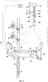
Фиг.1 - вид в перспективе системы управления согласно изобретению;Figure 1 is a perspective view of a control system according to the invention;
Фиг.2, 3 и 4 - виды сверху системы с фиг.1 при минимальном, промежуточном и максимальном выдвижениях штока приводного механизма, соответственно;Figure 2, 3 and 4 are top views of the system of figure 1 with minimum, intermediate and maximum extensions of the stem of the drive mechanism, respectively;
Фиг.5 - вид в продольном разрезе системы управления с фиг.1-4, для частного случая, когда устройство с изменяемой геометрией выполнено в виде устройства отбора воздуха из корпуса высокого давления;FIG. 5 is a longitudinal sectional view of the control system of FIGS. 1-4, for a particular case when the device with variable geometry is made in the form of a device for taking air from a high pressure housing;
Фиг.6 - вариант системы расцепления, позволяющей создать зону «мертвого хода»; и6 is a variant of a trip system that allows you to create a zone of "backlash"; and
Фиг.7 - график, иллюстрирующий управление устройствами системы управления согласно изобретению, включающей в себя устройство расцепления с фиг.6.FIG. 7 is a graph illustrating device management of a control system according to the invention, including the trip device of FIG. 6.
Далее со ссылками на фиг.1-4 приводится описание одного из вариантов реализации изобретения системы 1 управления согласно изобретению.Next, with reference to figures 1-4 is a description of one embodiment of the invention of the control system 1 according to the invention.
Система 1 управления позволяет управлять одновременно вращением кольца 22 управления ступени 10 лопаток с переменным углом установки (первое устройство 10) и перемещением органа 115 управления второго устройства 110.The control system 1 allows you to simultaneously control the rotation of the
Второе устройство 110 с изменяемой геометрией может быть разных типов, например, оно может быть выполнено в виде клапана отбора воздуха турбомашины.The second
Ступень 10 лопаток с переменным углом установки, например, образует компрессор турбомашины. Компрессор содержит кольцеобразную оболочку 12 статора (или корпуса компрессора), которая центрирована относительно оси Х-Х турбомашины.
Ступень 10 состоит из множества лопаток 14, расположенных в радиальном направлении вокруг оси Х-Х турбомашины. Каждая из лопаток 14 способна вращаться вокруг оси 16 (или штифта), которая проходит через корпус 12 компрессора.
Каждый штифт 16 лопаток 14 с переменным углом установки присоединен к концу связи или рычага 18 управления, другой конец которого шарнирно закреплен вокруг стержней 19, расположенных в радиальном направлении по кольцу 22 управления.Each
Кольцо 22 управления окружает корпус компрессора 12 и центрировано относительно оси Х-Х турбомашины. Синхронизированное изменение углового положения лопаток 14 обеспечивается, таким образом, за счет вращения кольца 22 управления вокруг оси Х-Х турбомашины.A
Кроме того, система управления содержит приводной механизм 24 типа гидроцилиндра, закрепленный на корпусе 12 компрессора для приведения во вращение кольца 22 управления ступени 10 посредством приводного органа 26 типа направляющего ролика, установленного с возможностью вращения на коробке 28 корпуса 12 компрессора турбомашины.In addition, the control system includes a hydraulic cylinder
Приводной механизм 24 управляется электронным блоком 100 управления (показанным на фиг.2-4).The
Поводок 32 управления, типа винтового талрепа, обеспечивает передачу движения от направляющего пилотного ролика 26 кольцу 22. Этот поводок проходит касательно по отношению к кольцу 22, к которому он прикреплен посредством соединительной скобы 27. На своем конце, противоположном относительно расположения скобы 27, поводок 32 прикреплен к рычагу (или плечу) 34 направляющего пилотного ролика 26 и шарнирно связан с ним.A
Направляющий ролик 26 и поводок 32 образуют совместно цепь передачи воздействия от приводного механизма 24 к кольцу 22 управления.The
Передача команды второму управляемому устройству 110 обеспечивается, прежде всего, посредством синхронизационной рейки 30.The transmission of the command to the second controlled
Синхронизационная рейка 30 передает движение от гидроцилиндра 24 второму устройству 110, посредством следящего органа 26' типа направляющего ролика, установленного также с возможностью вращения на узле 28 корпуса 12 компрессора.The
Таким образом, синхронизационная рейка 30 системы управления объединяет два рычага 38 и 40, соответственно, направляющих роликов, пилотного 26 и следящего 26', с которыми она шарнирно связана. Приводной механизм 24 шарнирно присоединен к третьему рычагу 42 направляющего пилотного ролика 26, расположенного напротив рычага 34, к которому прикреплен поводок 32.Thus, the
Кроме того, система управления, представленная на фиг.1-4, содержит устройство 20 усиления управления (не существенное для изобретения), установленное на блоке соединения приводного механизма 24 с устройством 110 с изменяемой геометрией.In addition, the control system shown in FIGS. 1-4 comprises a control amplification device 20 (not essential to the invention) mounted on a connection block of the
Это устройство содержит, в частности, дополнительный поворотный орган 44 (или дополнительный направляющий ролик), установленный между следящим органом 26' и устройством 110 с изменяемой геометрией. Этот дополнительный направляющий ролик 44 установлен с возможностью вращения одновременно относительно следящего органа 26' и косвенно относительно корпуса 12 компрессора посредством направляющей тяги 50 и поворотной опоры 54.This device includes, in particular, an additional pivoting member 44 (or an additional guide roller) mounted between the follower 26 'and the
На самом деле, дополнительный направляющий ролик 44 содержит рычаг 46, первый конец которого шарнирно соединен с концом 62 кабеля 60 управления устройства 110 с изменяемой геометрией, а второй конец установлен с возможностью вращения на конце рычага 36 направляющего следящего ролика 26'. На уровне этого второго конца рычага 46, дополнительный направляющий ролик 44 содержит также ось 48 направляющего ролика, проходящую перпендикулярно первому рычагу 46 вдоль поворотной оси Z дополнительного направляющего ролика 44 на следящий орган 26'. Направляющая тяга 50 проходит через эту ось направляющего ролика 48. Она установлена со скользящей посадкой внутри кольца 52 скольжения, которое установлено с возможностью вращения на корпусе 12 компрессора, посредством поворотной опоры 54, приваренной к корпусу.In fact, the
Соединение между устройством 20 усиления управления и устройством 110 с изменяемой геометрией обеспечивается дистанционно посредством кабеля 60 механизма тянуще-толкающего типа (например, кабеля 'Bowden') и скользящего стыковочного органа 120.The connection between the
Действие приводного механизма 24, передаваемое направляющим роликом 26, синхронизационной рейкой 30 и следящим направляющим роликом 26', усиленное затем устройством 20 усиления управления (работа этого устройства будет описано далее), передается кабелю 60 управления.The action of the
Конец 64 кабеля 60 управления присоединен к средней части хомута или U-образной детали 126. Два плеча хомута 126 огибают с одной и с другой стороны орган 115 устройства 110 с изменяемой геометрией, который управляет перемещениями устройства 110 с изменяемой геометрией в направлении, указанном стрелкой А. Этот орган 115 управления имеет вид прямоугольной пластины, в которой просверлено овальное отверстие 124. Оба плеча хомута 126 соединяются между собой посредством штанги 122, проходящей через овальное отверстие 124.The
Хомут 126 и штанга 122, скользящая в отверстии вытянутой формы 124, образуют совместно скользящий стыковочный орган 120. Приводной механизм 24 приводит в движение, через этот скользящий стыковочный орган 120, второе устройство 110, перемещение которого соответствует зоне мертвого хода. В самом деле, пока штанга 122 перемещается внутри отверстия вытянутой формы 124 вплоть до блокировки ее перемещения концом последнего, ее перемещение не вызывает никакого движения органа 115 управления, другими словами движения приводного механизма (гидроцилиндра 24) не вызывают никакого движения органа 115 управления устройства 110.The
Следует также отметить, что согласно другому варианту изобретения (не описанному в описании), конец 62 кабеля 60 управления может быть непосредственно присоединен к концу рычага 36 следящего направляющего ролика 26' (см. фиг.1), что позволяет получить длину хода, идентичную длине хода первого управляемого устройства 10 (кольцо 22 управления ступени 10 лопаток с переменным углом установки). Этот вариант изобретения предназначен для того случая применения, когда для управления вторым устройством не требуется увеличения длины хода управления.It should also be noted that according to another embodiment of the invention (not described in the description), the
Для облегчения понимания работы системы 1 управления, на фиг.2-4 показано движение этой системы в трех положениях, соответствующих минимальному, промежуточному и максимальному выдвижениям штока приводного механизма 24. В системе 1 управления, перемещение приводного механизма 24 представляет собой параметр управления этим приводным механизмом.To facilitate understanding of the operation of the control system 1, FIGS. 2-4 show the movement of this system in three positions corresponding to the minimum, intermediate and maximum extensions of the stem of the
На фиг.2 показано, например, начало управления этими устройствами. В самом начале своего срабатывания (см. фиг.2) приводной механизм находится в положении, соответствующем минимальному выдвижению его штока, и лопатки 14 с переменным углом установки находятся в открытом положении.Figure 2 shows, for example, the beginning of the management of these devices. At the very beginning of its operation (see figure 2), the drive mechanism is in a position corresponding to the minimum extension of its rod, and the
Начиная с этого положения, воздействие приводного механизма 24 приводит к вращению пилотного направляющего ролика 26, а за ним и другого следящего направляющего ролика 26', приводимого в движение посредством синхронизационной рейки 30. Вращение направляющего ролика 26 вокруг его поворотной оси, находящейся на узле 28, приводит в свою очередь в движение поводок 32, который заставляет поворачиваться в итоге в одну или другую сторону кольцо 22 вокруг оси Х-Х турбомашины. Как это было показано выше, вращение кольца 22 вызывает одновременное изменение углового положения лопаток 14 ступени 10, осуществляемое посредством рычагов 18 управления.Starting from this position, the action of the
С другой стороны, вращение направляющего ролика 26' приводит во вращение, с изменением угла передачи относительно вращения направляющего ролика 26', дополнительный направляющий ролик 44. Изменение угла связано с тем обстоятельством, что поворот следящего направляющего ролика 26' заставляет ось (рычаг 48) дополнительного направляющего ролика 44 пройти очень близко от поворотной точки на корпусе компрессора (поворотная опора 54). В этих условиях очень слабое вращение следящего направляющего ролика 26' вызывает очень сильное (относительно) вращение дополнительного направляющего ролика 44.On the other hand, rotation of the guide roller 26 'causes, with a change in the transmission angle relative to the rotation of the guide roller 26', an
Вращение дополнительного направляющего ролика 44 вызывает скольжение как кабеля 60 управления внутри его оболочки, так и хомута 126, которые толкают рычаг 46 дополнительного направляющего ролика 44.The rotation of the
Фиг.3 соответствует особому положению штока приводного механизма 24 при его выдвижении.Figure 3 corresponds to the special position of the rod of the
При выдвижении приводным механизмом 24 своего штока, кабель 60 управления толкает хомут 126 и штангу 122 в овальное отверстие 124 в направлении стрелки А. Положение, представленное на фиг.3, соответствует в точности тому моменту, когда штанга 122, жестко связанная с хомутом 126, упирается в конец отверстия 124, двигаясь в направлении стрелки А (которое представляет собой, для органа 115 управления, направление приложения воздействия), причем это положение, начиная с которого штанга 122 начинает перемещать орган управления (пластина 115) устройства 110 с изменяемой геометрией. И наоборот, начиная с начала выдвижения штока приводного механизма 24 и вплоть до достижения им этого положения, орган 115 управления не покидает своего исходного положения (см. фиг.2), и это несмотря на перемещение хомута 126. Поэтому диапазон управления приводного механизма 24, между его исходным положением (см. фиг.2) и промежуточным положением (см. фиг.3), представляет собой зону мертвого хода для второго управляемого устройства 110.When the
Начиная со специфического положения или положения начала управления, представленного на фиг.3, любое дополнительное перемещение приводного механизма 24 вынуждает штангу 122, жестко связанную с хомутом 126, выталкивать в направлении стрелки А орган 115 управления и вызывает перемещение последнего. Положения приводного механизма 24, заходящие за это положение или соответствующие ему, представляют собой диапазон управления вторым устройством 110.Starting from the specific position or position of the start of control shown in FIG. 3, any additional movement of the
Кроме того, следует отметить, что как только приводной механизм 54 превышает это положение начала управления, пружина 112 срабатывает как средство возврата, позволяющее удержать орган 115 управления в постоянном контакте со штангой 122. Таким образом, орган 115 управления отслеживает в каждый момент времени перемещения штанги 122, как в направлении стрелки А, так и в противоположном направлении. И, наоборот, на протяжении мертвого хода скользящего стыковочного органа 120, орган 115 управления остается блокированным в положении «низкое» на фиг.2 и 3.In addition, it should be noted that as soon as the
Наконец, система управления содержит датчик 114 положения, расположенный вблизи устройства с изменяемой геометрией и способный передавать информацию, касающуюся положения устройства 110 с изменяемой геометрией. В рассматриваемом варианте реализации изобретения, датчик 114 предназначен для определения положения органа 115 управления устройства 110 с изменяемой геометрией и передачи этой информации в электронный блок 100 управления.Finally, the control system includes a
Ниже, со ссылкой на фиг.5 описан вариант реализации системы 2 управления согласно изобретению. На этом чертеже показан особый случай, в котором второе устройство с изменяемой геометрией представляет собой систему 210 отбора воздуха, состоящую из набора устройств 136 отбора воздуха.Below, with reference to FIG. 5, an embodiment of a
Система управления 2 очень близка по своей работе системе, описанной со ссылкой на фиг.1-4; причем для одинаковых элементов сохранены те же ссылочные позиции.The
На фиг.5 показан частичный разрез турбомашины 150, которая представляет собой турбореактивный двухконтурный двигатель. Во входной части турбомашины 150 поток воздуха, поступающий в турбомашину, разделяется на первичный поток 146 и вторичный поток 148. Первичный поток представляет собой окислитель топлива, обеспечивающий возможность горения топлива, впрыскиваемого в камеру сгорания.Figure 5 shows a partial section of a
Первая часть энергии, высвободившейся в результате сжигания топлива, используется посредством первой турбины (турбины высокого давления) в основном первом блоке турбомашины, то есть в корпусе 151 высокого давления. Корпус высокого давления получил такое название ввиду того, что газы, входящие в состав первичного потока, сжимаются перед их впуском в камеру сгорания до высокого давления компрессором 152, называемым компрессором высокого давления, часть которого показана на фиг.5.The first part of the energy released as a result of fuel combustion is used by the first turbine (high pressure turbine) in the main first block of the turbomachine, that is, in the
Вторая часть энергии, высвободившейся в результате сжигания топлива, используется посредством второй турбины во втором основном блоке турбомашины в корпусе 153 низкого давления. Этот корпус низкого давления содержит, по меньшей мере, одну ступень лопаток (лопатки воздуходувки), приводимых во вращение таким образом, чтобы создавать за счет реакции наибольшую часть тяги, создаваемой турбомашиной 150.The second part of the energy released as a result of fuel combustion is used by the second turbine in the second main turbomachine unit in the
В силу указанных особенностей, корпусы высокого и низкого давления относительно независимы один от другого; в частности, это касается пределов скоростей вращения. Из этого следует, что команды, подлежащие подаче их устройству, могут быть обоснованы, в зависимости от конкретного случая, соображениями, полностью отличными или независимыми друг от друга.Due to these features, high and low pressure housings are relatively independent of one another; in particular, this applies to the limits of rotation speeds. It follows that the commands to be given to their device can be justified, as the case may be, by considerations completely different or independent from each other.
Как известно, при прохождении вторичного потока воздуха по турбомашине в направлении из ее входной части в выходную, вторичный поток воздуха подвергается сжатию вначале в компрессоре низкого давления, а затем - в компрессоре высокого давления; потом он попадает в камеру сгорания, а затем расширяется, проходя последовательно через турбины высокого и низкого давления. Компрессор высокого давления располагается таким образом за компрессором низкого давления.As you know, when passing the secondary air stream through the turbomachine in the direction from its inlet to the outlet, the secondary air stream is compressed first in the low-pressure compressor, and then in the high-pressure compressor; then it enters the combustion chamber, and then expands, passing sequentially through high and low pressure turbines. The high-pressure compressor is thus located behind the low-pressure compressor.
Первичный 146 и вторичный 148 потоки проходят через турбомашину 150 по ее кольцеобразным концентрическим проходам, обозначенным ссылочными позициями 156 и 158, соответственно. Проход 156 первичного потока проходит между наружным 138 и внутренним обтекателями 140. Проход 158 вторичного потока проходит между наружным обтекателем, не представленным в описании, который представляет собой внутренний обтекатель гондолы, и внутренним обтекателем 142.Primary 146 and secondary 148 flows pass through
Система 2 управления располагается между обтекателями 138 и 142, отделяющими друг от друга первичный и вторичный потоки.The
Как правило, управление положением лопаток ступеней лопаток с переменным углом установки осуществляется в зависимости от давления окружающей среды и скорости вращения корпуса высокого давления.As a rule, the position of the blades of the blade stages with a variable installation angle is controlled depending on the ambient pressure and the rotation speed of the high-pressure housing.
С другой стороны, как правило, управление открытием устройств 136 отбора воздуха выполняется в зависимости от давления окружающей среды и расхода воздуха на выходе из компрессора низкого давления. Таким образом, отбор воздуха из вторичного потока за компрессором низкого давления производится для того, чтобы изменить режим работы этого компрессора.On the other hand, as a rule, the opening control of the
Несмотря на то что обычные параметры управления ступенями лопаток с переменным углом установки и устройствами отбора воздуха, о которых уже упоминалось выше, и отличаются друг от друга, система 2 управления позволяет, тем не менее, осуществлять управление двумя устройствами: с одной стороны - ступенями 10, 10', 10” лопаток с переменным углом установки; и с другой стороны - устройством 210 с изменяемой геометрией, состоящим из набора устройств 136 отбора воздуха.Despite the fact that the usual parameters for controlling the steps of blades with a variable installation angle and air sampling devices, which were already mentioned above, differ from each other, the
Ступени 10, 10' и 10” лопаток с переменным углом установки содержат соответственно три ряда лопаток 14, 14' и 14”, способных поворачиваться вокруг осей 16, 16', 16”. Два лопастных колеса 15, 15' с установленными на них подвижными лопатками 17, 17' вставлены между ступенями 10 и 10', 10' и 10”, соответственно.The
В целях упрощения, на чертеже представлено управление только первой ступенью 10 лопаток и не представлено управление другими ступенями 10', 10”. Управление этой ступенью идентично управлению, приведенному при описании фиг.1-4. Второе управляемое устройство представляет собой набор устройств 136 отбора воздуха. В нижеследующем описании описано только одно устройство отбора воздуха; однако в действительности, турбомашина содержит целый набор идентичных устройств, распределенных в обтекателе 138 по всей периферии турбомашины и управляемых аналогично управлению вышеописанным устройством 136 отбора воздуха.In order to simplify, the drawing shows the control of only the
Устройство 136 отбора воздуха выполняет несколько функций. Одна из функций заключается в том, чтобы в случае чрезмерной перегрузки влагой воздуха, засасываемого в турбомашину (дождем, снегом или градом), обеспечивалось удаление из первичного потока части этого воздуха во избежание нарушения процесса сжигания топлива, которое может произойти вследствие присутствия чрезмерного количества воды в горючей смеси. Другая функция устройства отбора воздуха заключается в разгрузке контура первичного потока в случае сильного торможения, или же в случае пониженного режима. Команда, выданная приводным механизмом 24, передается устройству 136 отбора воздуха, кабелю 60, хомуту 126 и органу 115 управления. Кабель 60 прикреплен к обтекателям 138, 142 посредством опор 130 и 132. Опора 130 служит также средством направления при перемещении хомута 126 и органа 115 управления.The
Управление устройством 136 отбора воздуха несколько отличается от управления устройством, показанным на фиг.1-4, а именно тем, что средство возврата (пружина 212) отличается по своей сути от пружины 112, представленной на фиг.1-4.The control of the air take-
Устройство 136 отбора воздуха способно поворачиваться вокруг оси 134 поворота (вращение по стрелке I). Как правило, оно закрыто и возвращается в закрытое положение с помощью пружины 212. Один конец пружины 212 закреплен на опоре 160, жестко связанной с обтекателем 142, тогда как другой конец воздействует с силой возврата на приводной рычаг 144, жестко связанный с устройством 136 отбора воздуха, которое закрывает устройство 136 отбора воздуха.The
Для открытия устройства 136, управление приводным механизмом 24 должно производиться тогда, когда последний находится в таком положении выдвижения своего штока, которое достаточно для перемещения органа 115 управления устройства 136 отбора воздуха (то есть за специфическим положением, представленным на фиг.3). Начиная с этого специфического положения и вне его или начиная с положения начала управления, параметр приводного механизма 24 меняет свое значение в диапазоне управления устройством 136 отбора воздуха. Первым следствием этого является то, что лопаткам 14 придается, в тех случаях, когда необходимо открыть устройство 136 отбора воздуха, угол установки, соответствующий сильному сжатию приводного механизма 24.To open the
В этом диапазоне управления хомут 126 перемещает орган 115 управления устройства 136 отбора воздуха. Этот орган 115 управления имеет форму пластины, продолжением которой является штанга 119. Конец штанги 119 опирается на приводной рычаг 144. Орган 115 управления при своем перемещении толкает рычаг 144, вызывая тем самым вращение и открытие устройства 136.In this control range, the
Воздух, отбираемый из первичного потока устройством 136 отбора воздуха, отводится затем во вторичную струю (этот этап не представлен на фиг.5). Этот воздух добавляется к воздуху, содержащемуся во вторичном потоке, движение которого ускоряется вследствие действия вентиляторных лопаток.Air drawn from the primary stream by the
Когда приводной механизм раздвинут или удлинен, то в тот момент, когда необходимо закрыть устройство 136 отбора воздуха, кабелем 60 управления затягивают назад хомут 126 и орган 115 управления. Устройство отбора воздуха 136 тогда закрывается под действием пружины 212.When the drive mechanism is extended or extended, then at the moment when it is necessary to close the
На фиг.6 представлена система 220 расцепления, входящая в состав системы управления двумя устройствами с изменяемой геометрией, состоящей из двух различных корпусов, причем второй из них представляет собой устройство 310. Система 220 расцепления сопоставима с системой расцепления, вариант реализации которой представлен на фиг.1-4, состоящей из скользящего стыковочного органа 120в. Как и последняя, система расцепления 220 также позволяет создавать зону «мертвого хода».FIG. 6 illustrates a tripping
Система расцепления 220 предназначена для размещения на конце кабеля 60 управления. Конец кабеля 60 прикреплен к приводной рейке 222, которая перпендикулярна оси В кабеля. Система 220 расцепления содержит также орган 215 управления. Последний содержит вытянутое в сторону оси В овальное отверстие 224, в которое проходит рейка 222. Таким образом, рейка 222 способна вызывать поступательное движение органа 215 управления как только последний упрется в конец овального отверстия 224. Работающая на сжатие пружина 312 возврата располагается между первым концом 217 органа 215 управления и опорой 360, жестко связанной с неподвижной частью 362 турбомашины. Пружина 312 воздействует на орган управления по оси B в направлении, соответствующем первому направлению перемещения кабеля 60 (стрелка С), при этом ее усилие прилагается к концу 217 органа 215 управления.The
Работа системы расцепления происходит следующим образом:The operation of the trip system is as follows:
В первом диапазоне значений приводного механизма, воздействующего на кабель 60 управления, штанга 222 упирается в конец овального отверстия 224, и пружина 312 сжимается. Движения органа управления 215 идентичны движениям штанги 222.In the first range of values of the drive mechanism acting on the
Во втором диапазоне значений приводного механизма, как только пружина 312 расправилась и достигла своего максимального удлинения, она уже более не играет никакой роли. Штанга 222 может под действием кабеля 60 перемещаться дальше, причем без того, чтобы возникала необходимость в перемещении органа 215 управления. Этот второй диапазон значений параметра управления представляет собой, таким образом, зону мертвого хода для второго управляемого устройства 310.In the second range of values of the drive mechanism, as soon as the
Орган 215 управления непосредственно не воздействует на это второе управляемое устройство 310. Второй конец 219 органа 215 управления, в противоположность первому концу 217, шарнирно прикреплен к концу 232 рычага 230. Другой конец 234 этого рычага 230 шарнирно прикреплен к управляемому устройству 310. Рычаг 230 позволяет таким образом увеличить, с коэффициентом, способным быть выше, равным или меньшим единицы, перемещение органа 215 управления; или даже изменить направление управления.The
На фиг.7 показано на более высоком теоретическом уровне, каким образом происходит управление двумя устройствами посредством системы управления, имеющей в своем составе устройство расцепления, подобное устройству 220 с фиг.6.FIG. 7 shows at a higher theoretical level how two devices are controlled by means of a control system incorporating a trip device similar to
Этот чертеж касается случая, когда первое управляемое устройство представляет собой ступень лопаток с переменным углом установки VSV, и когда второе устройство состоит из набора вентилей отбора воздуха VBV.This drawing relates to the case when the first controllable device is a stage of blades with a variable installation angle VSV, and when the second device consists of a set of VBV air sampling valves.
По абсциссе x отложены изменения параметра приводного механизма, то есть более или менее значительные выдвижения штока приводного механизма 24. Этот параметр x меняется между положением, которое соответствует замедленному или пониженному режиму работы турбомашины, и финальным положением, которое соответствует максимальному режиму турбомашины.The abscissa x represents the changes in the parameter of the drive mechanism, i.e., more or less significant extensions of the stem of the
По ординате отложены углы открытия соответственно лопаток с переменным углом установки VSV и заслонок отбора воздуха VBV. Углы меняются для каждого из двух устройств в диапазоне между двумя положениями, обозначенными буквами O (открыт) и С (закрыт). Закон управления ступенью лопаток VSV представлен нижней кривой. Он демонстрирует постепенное открытие лопаток, в диапазоне управления Е. В соответствии с компоновкой системы управления, открытие может быть более или менее резким, что выражается наличием у этой кривой более или менее выраженного наклона.According to the ordinate, the opening angles of the blades with a variable installation angle VSV and the air intake dampers VBV are plotted. The angles vary for each of the two devices in the range between the two positions indicated by the letters O (open) and C (closed). The law of blade stage control VSV is represented by the bottom curve. It demonstrates the gradual opening of the blades, in the control range E. In accordance with the layout of the control system, the opening can be more or less sharp, which is expressed by the presence of a more or less pronounced slope in this curve.
Закон управления заслонками отбора воздуха VBV представлен верхней кривой. Заслонки отбора воздуха VBV закрываются постепенно, по мере того как увеличивается параметр управления x (выдвижение штока приводного механизма 24), внутри соответственно диапазона управления D.The VBV air intake flap control law is represented by the upper curve. The VBV air intake flaps close gradually as the control parameter x (extension of the actuator stem 24) increases, within the corresponding control range D.
Как это видно из фиг.7, в диапазоне закрытия заслонок отбора воздуха VBV, который соответствует относительно слабым режимам турбомашины, лопатки с переменным углом установки VSV по существу закрыты; и только в том случае, когда заслонки отбора воздуха VBV совершенно закрыты, начинается открытие лопаток с переменным углом установки VSV.As can be seen from Fig. 7, in the closing range of the VBV air sampling flaps, which corresponds to relatively weak turbomachine modes, the variable-angle blades of the VSV are essentially closed; and only when the VBV air sampling flaps are completely closed, does the opening of the blades with a variable installation angle of the VSV begin.
Точно также, только после полного закрытия заслонок отбора воздуха VBV начнется открытие лопаток с переменным углом установки VSV. Это позволяет понять, что при использовании единого приводного механизма, входящего в состав системы управления согласно изобретению, возможно точное управление положением как лопаток с переменным углом установки, так и заслонок отбора воздуха.Similarly, only after the VBV air sampling flaps are completely closed will the opening of the vanes with a variable angle of installation of the VSV begin. This makes it possible to understand that when using a single drive mechanism included in the control system according to the invention, it is possible to precisely control the position of both the blades with a variable installation angle and the air sampling flaps.
Устройство 120 расцепления на фиг.1-5 имело зону мертвого хода в начале диапазона изменения параметра управления.The tripping
Напротив, в устройстве 220 расцепления, используемом в системе управления с фиг.7, зона мертвого хода располагается в конце диапазона изменения параметра управления (для значений, отложенных на абсциссе x).In contrast, in the
Система управления работает таким образом, чтобы при закрытии заслонок отбора воздуха VBV начало открытия лопаток VSV происходило в процессе закрытия заслонок VBV (то есть так, чтобы лопатки VSV начинали открываться, частично открываясь с открытием, меньшим 50%, например, меньшим 20%). Такая работа системы облегчается благодаря применению устройства усиления управления, которое позволяет обеспечить полное закрытие заслонок VBV в диапазоне управления Н, отличающемся, однако, слабой амплитудой. Таким образом, за счет использования соответствующего устройства усиления можно управлять устройством 310 с изменяемой геометрией в режиме уменьшенного диапазона управления, составляющего, например, 20%, даже 10% или даже 5% от полного диапазона управления приводного механизма.The control system works in such a way that when closing the VBV air sampling flaps, the opening of the VSV vanes begins during the closing of the VBV valves (i.e., so that the VSV vanes begin to open, partially opening with an opening of less than 50%, for example, less than 20%). This operation of the system is facilitated by the use of a control amplification device, which allows full closure of the VBV dampers in the control range H, which differs, however, in low amplitude. Thus, by using an appropriate amplification device, the
Затем, при закрытых или, по меньшей мере, по существу закрытых заслонках отбора воздуха VBV, система управления способна и позволяет реализовать наибольшие возможности по закрытию лопаток ступени лопаток с переменным углом установки. Таким образом, в том случае, когда заслонки VBV закрыты и таким образом не могут быть приведены в движение приводным механизмом, последний остается полностью готовым к работе для воздействия на другое устройство и регулирования работы последнего, а именно лопаток ступени лопаток с переменным углом установки.Then, with closed or at least substantially closed VBV air sampling flaps, the control system is capable and allows to realize the greatest possibilities for closing the blades of the blade stage with a variable installation angle. Thus, in the case when the VBV shutters are closed and thus cannot be set in motion by the drive mechanism, the latter remains completely ready to work for acting on another device and regulating the operation of the latter, namely, the blades of the blade stage with a variable installation angle.
Claims (13)
Applications Claiming Priority (3)
| Application Number | Priority Date | Filing Date | Title |
|---|---|---|---|
| FR0856573A FR2936559B1 (en) | 2008-09-30 | 2008-09-30 | SYSTEM FOR CONTROLLING EQUIPMENT WITH VARIABLE GEOMETRY OF A TURBOMACHINE CONSISTING OF DIFFERENT BODIES. |
| FR0856573 | 2008-09-30 | ||
| PCT/FR2009/051791 WO2010037949A1 (en) | 2008-09-30 | 2009-09-23 | System for controlling variable geometry apparatuses in a turbine engine |
Publications (2)
| Publication Number | Publication Date |
|---|---|
| RU2011117534A RU2011117534A (en) | 2012-11-10 |
| RU2529762C2 true RU2529762C2 (en) | 2014-09-27 |
Family
ID=40566183
Family Applications (1)
| Application Number | Title | Priority Date | Filing Date |
|---|---|---|---|
| RU2011117534/06A RU2529762C2 (en) | 2008-09-30 | 2009-09-23 | System for controlling variable geometry devices in turbo machines and turbo machine having said system |
Country Status (10)
| Country | Link |
|---|---|
| US (1) | US8591173B2 (en) |
| EP (1) | EP2331791B1 (en) |
| JP (1) | JP5559179B2 (en) |
| CN (1) | CN102171417B (en) |
| BR (1) | BRPI0919524B1 (en) |
| CA (1) | CA2738219C (en) |
| ES (1) | ES2391705T3 (en) |
| FR (1) | FR2936559B1 (en) |
| RU (1) | RU2529762C2 (en) |
| WO (1) | WO2010037949A1 (en) |
Families Citing this family (24)
| Publication number | Priority date | Publication date | Assignee | Title |
|---|---|---|---|---|
| FR2936556B1 (en) * | 2008-09-30 | 2015-07-24 | Snecma | SYSTEM FOR CONTROLLING EQUIPMENT WITH VARIABLE GEOMETRY OF A TURBOMACHINE, IN PARTICULAR BY GUIGNOLS. |
| FR2947310B1 (en) | 2009-06-26 | 2014-08-29 | Snecma | DEVICE AND METHOD FOR POSITIONING A VARIABLE GEOMETRY EQUIPMENT FOR A TURBOMACHINE USING A RELATIVE MEASURING CYLINDER. |
| FR2972505B1 (en) * | 2011-03-07 | 2014-02-14 | Snecma | METHOD AND MONITORING DEVICE FOR SERVOVALVE ACTUATION SYSTEM |
| US9103228B2 (en) * | 2011-08-08 | 2015-08-11 | General Electric Company | Variable stator vane control system |
| FR2990241B1 (en) * | 2012-05-07 | 2014-06-06 | Snecma | METHOD FOR IMPROVED MOUNTING OF A CONTROL JACK FOR AN AIR DISCHARGE VALVE OF A TURBOMACHINE |
| US9062603B2 (en) | 2012-06-20 | 2015-06-23 | United Technologies Corporation | Four bar drive mechanism for bleed system |
| US9091209B2 (en) | 2012-06-20 | 2015-07-28 | United Technologies Corporation | Four bar bracket |
| US9422825B2 (en) * | 2012-11-05 | 2016-08-23 | United Technologies Corporation | Gas turbine engine synchronization ring |
| EP2971657B1 (en) * | 2013-03-12 | 2021-08-04 | Raytheon Technologies Corporation | Expanding shell flow control device |
| GB201317924D0 (en) * | 2013-10-10 | 2013-11-27 | Rolls Royce Plc | Gas turbine engine |
| US9732624B2 (en) | 2014-07-10 | 2017-08-15 | Hamilton Sundstrand Corporation | Hot environment vane angle measurement |
| FR3031772B1 (en) * | 2015-01-19 | 2017-01-13 | Snecma | VARIABLE TIMING AUB CONTROL SYSTEM FOR TURBOMACHINE |
| US9885314B2 (en) * | 2015-03-02 | 2018-02-06 | The Boeing Company | Dual-cam bellcrank mechanism |
| FR3039207B1 (en) * | 2015-07-21 | 2019-07-26 | Safran Aircraft Engines | EXHAUST CASE OF A TURBOMACHINE WITH INCREASED LIFETIME |
| JP6674763B2 (en) * | 2015-11-04 | 2020-04-01 | 川崎重工業株式会社 | Variable vane operating device |
| US10399687B2 (en) * | 2015-12-03 | 2019-09-03 | The Boeing Company | Methods and apparatus to vary an air intake of aircraft engines |
| US10408217B2 (en) | 2016-03-15 | 2019-09-10 | General Electric Company | Controlling a compressor of a gas turbine engine |
| US10634000B2 (en) * | 2017-06-23 | 2020-04-28 | Rolls-Royce North American Technologies Inc. | Method and configuration for improved variable vane positioning |
| GB201808852D0 (en) * | 2018-05-31 | 2018-07-18 | Rolls Royce Plc | Gas turbine engine |
| FR3100273B1 (en) * | 2019-08-27 | 2021-10-15 | Safran Aircraft Engines | GUIGNOL FOR A VARIABLE TIMING DEVICE OF A TURBOMACHINE |
| FR3100272A1 (en) * | 2019-08-27 | 2021-03-05 | Safran Aircraft Engines | GUIGNOL FOR A VARIABLE TIMING DEVICE OF A TURBOMACHINE |
| FR3108362B1 (en) * | 2020-03-19 | 2022-07-29 | Safran Aircraft Engines | Stage of blades with variable orientation for an axial turbomachine comprising a member for regulating the air flow depending on the orientation of the blades |
| DE102022103922A1 (en) * | 2022-02-18 | 2023-08-24 | MTU Aero Engines AG | LEVER FOR ADJUSTING AN ADJUSTABLE BLADE |
| FR3133214A1 (en) * | 2022-03-03 | 2023-09-08 | Safran Aircraft Engines | IMPROVED SYSTEM FOR CONTROLLING RECTIFIER BLADE OF A COMPRESSOR FOR AIRCRAFT TURBOMACHINE |
Citations (6)
| Publication number | Priority date | Publication date | Assignee | Title |
|---|---|---|---|---|
| US3638428A (en) * | 1970-05-04 | 1972-02-01 | Gen Electric | Bypass valve mechanism |
| US4292802A (en) * | 1978-12-27 | 1981-10-06 | General Electric Company | Method and apparatus for increasing compressor inlet pressure |
| US4403912A (en) * | 1981-03-23 | 1983-09-13 | Avco Corporation | Integrated multiplane actuator system for compressor variable vanes and air bleed valve |
| FR2611230A1 (en) * | 1987-02-25 | 1988-08-26 | Snecma | Turbine machine including a device for controlling the throughput of air for cooling the turbine |
| US6742324B2 (en) * | 2002-09-13 | 2004-06-01 | General Electric Company | Methods and apparatus for supporting variable bypass valve systems |
| RU2287064C2 (en) * | 2004-12-07 | 2006-11-10 | Федеральное государственное унитарное предприятие "Московское машиностроительное производственное предприятие "САЛЮТ" (ФГУП "ММПП "САЛЮТ") | Stator of compressor of gas-turbine engine |
Family Cites Families (8)
| Publication number | Priority date | Publication date | Assignee | Title |
|---|---|---|---|---|
| US4992946A (en) * | 1988-06-20 | 1991-02-12 | General Electric Company | Data link for gas turbine engine control |
| FR2640685B1 (en) * | 1988-12-15 | 1991-02-08 | Snecma | TURBOREACTOR COMPRESSOR DISCHARGE VALVE |
| EP1669548A1 (en) | 2004-12-08 | 2006-06-14 | ABB Turbo Systems AG | Guide vane apparatus for a gas turbine engine |
| FR2885969B1 (en) * | 2005-05-17 | 2007-08-10 | Snecma Moteurs Sa | TURBOMACHINE VARIABLE ROTATION ANGLE STATOR AUTONER STAGE CONTROL SYSTEM |
| GB2473578B (en) * | 2006-01-20 | 2011-08-03 | Rolls Royce Power Eng | Gas turbine engine system |
| FR2936561B1 (en) * | 2008-09-30 | 2018-10-26 | Safran Aircraft Engines | SYSTEM FOR CONTROLLING AT LEAST TWO VARIABLE GEOMETRY EQUIPMENTS OF A GAS TURBINE ENGINE, IN PARTICULAR BY A CAM MECHANISM |
| FR2936565B1 (en) * | 2008-09-30 | 2015-07-24 | Snecma | SYSTEM FOR CONTROLLING EQUIPMENT WITH VARIABLE GEOMETRY OF A TURBOMACHINE IN PARTICULAR BY ARTICULATED GUIGNOLS. |
| FR2936560B1 (en) * | 2008-09-30 | 2014-06-27 | Snecma | SYSTEM FOR CONTROLLING AT LEAST TWO VARIABLE GEOMETRY EQUIPMENTS OF A GAS TURBINE ENGINE, IN PARTICULAR BY CREMAILLERE |
-
2008
- 2008-09-30 FR FR0856573A patent/FR2936559B1/en active Active
-
2009
- 2009-09-23 CN CN200980138753.6A patent/CN102171417B/en active Active
- 2009-09-23 CA CA2738219A patent/CA2738219C/en active Active
- 2009-09-23 RU RU2011117534/06A patent/RU2529762C2/en active
- 2009-09-23 WO PCT/FR2009/051791 patent/WO2010037949A1/en active Application Filing
- 2009-09-23 US US13/121,700 patent/US8591173B2/en active Active
- 2009-09-23 ES ES09747898T patent/ES2391705T3/en active Active
- 2009-09-23 EP EP09747898A patent/EP2331791B1/en active Active
- 2009-09-23 BR BRPI0919524A patent/BRPI0919524B1/en active IP Right Grant
- 2009-09-23 JP JP2011529597A patent/JP5559179B2/en active Active
Patent Citations (6)
| Publication number | Priority date | Publication date | Assignee | Title |
|---|---|---|---|---|
| US3638428A (en) * | 1970-05-04 | 1972-02-01 | Gen Electric | Bypass valve mechanism |
| US4292802A (en) * | 1978-12-27 | 1981-10-06 | General Electric Company | Method and apparatus for increasing compressor inlet pressure |
| US4403912A (en) * | 1981-03-23 | 1983-09-13 | Avco Corporation | Integrated multiplane actuator system for compressor variable vanes and air bleed valve |
| FR2611230A1 (en) * | 1987-02-25 | 1988-08-26 | Snecma | Turbine machine including a device for controlling the throughput of air for cooling the turbine |
| US6742324B2 (en) * | 2002-09-13 | 2004-06-01 | General Electric Company | Methods and apparatus for supporting variable bypass valve systems |
| RU2287064C2 (en) * | 2004-12-07 | 2006-11-10 | Федеральное государственное унитарное предприятие "Московское машиностроительное производственное предприятие "САЛЮТ" (ФГУП "ММПП "САЛЮТ") | Stator of compressor of gas-turbine engine |
Also Published As
| Publication number | Publication date |
|---|---|
| CN102171417B (en) | 2015-05-20 |
| CA2738219A1 (en) | 2010-04-08 |
| FR2936559B1 (en) | 2013-11-22 |
| US20110182716A1 (en) | 2011-07-28 |
| ES2391705T3 (en) | 2012-11-29 |
| CA2738219C (en) | 2016-05-31 |
| CN102171417A (en) | 2011-08-31 |
| FR2936559A1 (en) | 2010-04-02 |
| BRPI0919524B1 (en) | 2020-06-09 |
| US8591173B2 (en) | 2013-11-26 |
| RU2011117534A (en) | 2012-11-10 |
| EP2331791B1 (en) | 2012-08-15 |
| WO2010037949A1 (en) | 2010-04-08 |
| BRPI0919524A2 (en) | 2015-12-08 |
| EP2331791A1 (en) | 2011-06-15 |
| JP2012504211A (en) | 2012-02-16 |
| JP5559179B2 (en) | 2014-07-23 |
Similar Documents
| Publication | Publication Date | Title |
|---|---|---|
| RU2529762C2 (en) | System for controlling variable geometry devices in turbo machines and turbo machine having said system | |
| JP5608657B2 (en) | System for controlling a variable geometry device of a gas turbine engine with a barrel link in particular | |
| US8337140B2 (en) | System for controlling at least two variable-geometry equipments of a gas turbine engine, particularly by rack | |
| EP2258926B1 (en) | Control mechanism | |
| US8328500B2 (en) | System for controlling variable-geometry equipments of a turbomachine, particularly by articulated bellcranks | |
| US8333546B2 (en) | System for controlling at least two variable-geometry equipments of a gas turbine engine, particularly by cam mechanism | |
| RU2501957C2 (en) | System to control equipment of gas turbine engine with variable geometry, in particular, by means of control levers | |
| JP5514354B2 (en) | Turbine engine with flow control fan and method of operation | |
| EP2136036B1 (en) | Multi-rotational crankshaft arrangement | |
| JP2009062993A (en) | Actuating device, bypass air bleed system equipped therewith, and turbojet engine comprising these | |
| EP3163053A1 (en) | Bleed valve arrangement for a gas turbine engine | |
| WO2008045094A1 (en) | Bifurcation and aft vent used to vary fan nozzle exit area | |
| US20110088403A1 (en) | Nozzle-area ratio float bias | |
| JP5364166B2 (en) | In particular, a system for controlling a variable geometry device with a guide track connection, in particular for a gas turbine engine with a guide track connection | |
| GB2119862A (en) | Variable stator vane (VSV) closed loop control system of a compressor | |
| US9926883B1 (en) | Gas turbine engine with axial flow fan with twin stream impeller and variable area bypass nozzle | |
| CN111188850B (en) | Actuator fault fixing system | |
| US20230228219A1 (en) | Bleed valve assemblies |
Legal Events
| Date | Code | Title | Description |
|---|---|---|---|
| PD4A | Correction of name of patent owner |