RU2525503C2 - Transmission control system - Google Patents
Transmission control system Download PDFInfo
- Publication number
- RU2525503C2 RU2525503C2 RU2012114838/11A RU2012114838A RU2525503C2 RU 2525503 C2 RU2525503 C2 RU 2525503C2 RU 2012114838/11 A RU2012114838/11 A RU 2012114838/11A RU 2012114838 A RU2012114838 A RU 2012114838A RU 2525503 C2 RU2525503 C2 RU 2525503C2
- Authority
- RU
- Russia
- Prior art keywords
- gearbox
- gear
- gears
- engine
- vehicle
- Prior art date
Links
- 230000005540 biological transmission Effects 0.000 title claims abstract description 26
- 238000000034 method Methods 0.000 claims description 14
- 230000001133 acceleration Effects 0.000 claims description 12
- 238000004364 calculation method Methods 0.000 claims description 5
- 230000004044 response Effects 0.000 claims description 2
- 239000000126 substance Substances 0.000 abstract 1
- 230000006870 function Effects 0.000 description 19
- 238000004590 computer program Methods 0.000 description 8
- 230000008901 benefit Effects 0.000 description 3
- 238000010586 diagram Methods 0.000 description 2
- 239000000446 fuel Substances 0.000 description 2
- 230000003213 activating effect Effects 0.000 description 1
- 230000004913 activation Effects 0.000 description 1
- 230000001419 dependent effect Effects 0.000 description 1
- 230000009347 mechanical transmission Effects 0.000 description 1
- 230000008569 process Effects 0.000 description 1
- 230000002311 subsequent effect Effects 0.000 description 1
Images


Classifications
-
- F—MECHANICAL ENGINEERING; LIGHTING; HEATING; WEAPONS; BLASTING
- F16—ENGINEERING ELEMENTS AND UNITS; GENERAL MEASURES FOR PRODUCING AND MAINTAINING EFFECTIVE FUNCTIONING OF MACHINES OR INSTALLATIONS; THERMAL INSULATION IN GENERAL
- F16H—GEARING
- F16H61/00—Control functions within control units of change-speed- or reversing-gearings for conveying rotary motion ; Control of exclusively fluid gearing, friction gearing, gearings with endless flexible members or other particular types of gearing
- F16H61/02—Control functions within control units of change-speed- or reversing-gearings for conveying rotary motion ; Control of exclusively fluid gearing, friction gearing, gearings with endless flexible members or other particular types of gearing characterised by the signals used
- F16H61/0202—Control functions within control units of change-speed- or reversing-gearings for conveying rotary motion ; Control of exclusively fluid gearing, friction gearing, gearings with endless flexible members or other particular types of gearing characterised by the signals used the signals being electric
- F16H61/0204—Control functions within control units of change-speed- or reversing-gearings for conveying rotary motion ; Control of exclusively fluid gearing, friction gearing, gearings with endless flexible members or other particular types of gearing characterised by the signals used the signals being electric for gearshift control, e.g. control functions for performing shifting or generation of shift signal
- F16H61/0213—Control functions within control units of change-speed- or reversing-gearings for conveying rotary motion ; Control of exclusively fluid gearing, friction gearing, gearings with endless flexible members or other particular types of gearing characterised by the signals used the signals being electric for gearshift control, e.g. control functions for performing shifting or generation of shift signal characterised by the method for generating shift signals
-
- F—MECHANICAL ENGINEERING; LIGHTING; HEATING; WEAPONS; BLASTING
- F16—ENGINEERING ELEMENTS AND UNITS; GENERAL MEASURES FOR PRODUCING AND MAINTAINING EFFECTIVE FUNCTIONING OF MACHINES OR INSTALLATIONS; THERMAL INSULATION IN GENERAL
- F16H—GEARING
- F16H59/00—Control inputs to control units of change-speed- or reversing-gearings for conveying rotary motion
- F16H59/14—Inputs being a function of torque or torque demand
- F16H59/18—Inputs being a function of torque or torque demand dependent on the position of the accelerator pedal
- F16H59/20—Kickdown
-
- F—MECHANICAL ENGINEERING; LIGHTING; HEATING; WEAPONS; BLASTING
- F16—ENGINEERING ELEMENTS AND UNITS; GENERAL MEASURES FOR PRODUCING AND MAINTAINING EFFECTIVE FUNCTIONING OF MACHINES OR INSTALLATIONS; THERMAL INSULATION IN GENERAL
- F16H—GEARING
- F16H59/00—Control inputs to control units of change-speed- or reversing-gearings for conveying rotary motion
- F16H59/36—Inputs being a function of speed
- F16H59/44—Inputs being a function of speed dependent on machine speed, e.g. the vehicle speed
-
- F—MECHANICAL ENGINEERING; LIGHTING; HEATING; WEAPONS; BLASTING
- F16—ENGINEERING ELEMENTS AND UNITS; GENERAL MEASURES FOR PRODUCING AND MAINTAINING EFFECTIVE FUNCTIONING OF MACHINES OR INSTALLATIONS; THERMAL INSULATION IN GENERAL
- F16H—GEARING
- F16H61/00—Control functions within control units of change-speed- or reversing-gearings for conveying rotary motion ; Control of exclusively fluid gearing, friction gearing, gearings with endless flexible members or other particular types of gearing
- F16H61/02—Control functions within control units of change-speed- or reversing-gearings for conveying rotary motion ; Control of exclusively fluid gearing, friction gearing, gearings with endless flexible members or other particular types of gearing characterised by the signals used
- F16H61/0202—Control functions within control units of change-speed- or reversing-gearings for conveying rotary motion ; Control of exclusively fluid gearing, friction gearing, gearings with endless flexible members or other particular types of gearing characterised by the signals used the signals being electric
- F16H61/0204—Control functions within control units of change-speed- or reversing-gearings for conveying rotary motion ; Control of exclusively fluid gearing, friction gearing, gearings with endless flexible members or other particular types of gearing characterised by the signals used the signals being electric for gearshift control, e.g. control functions for performing shifting or generation of shift signal
- F16H61/0213—Control functions within control units of change-speed- or reversing-gearings for conveying rotary motion ; Control of exclusively fluid gearing, friction gearing, gearings with endless flexible members or other particular types of gearing characterised by the signals used the signals being electric for gearshift control, e.g. control functions for performing shifting or generation of shift signal characterised by the method for generating shift signals
- F16H2061/022—Calculation or estimation of optimal gear ratio, e.g. best ratio for economy drive or performance according driver preference, or to optimise exhaust emissions
Landscapes
- Engineering & Computer Science (AREA)
- General Engineering & Computer Science (AREA)
- Mechanical Engineering (AREA)
- Control Of Transmission Device (AREA)
Abstract
Description
Область техникиTechnical field
Настоящее изобретение относится к системе управления коробкой передач. В частности, изобретение относится к системе согласно ограничительной части п.1 формулы изобретения. Изобретение относится также к способу, транспортному средству, компьютерной программе и компьютерному программному продукту.The present invention relates to a transmission control system. In particular, the invention relates to a system according to the preamble of
Уровень техникиState of the art
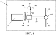
На фиг.1 схематично изображены части силовой передачи транспортного средства 1, такого как пассажирский автомобиль или тяжелое транспортное средство, например грузовик или автобус. Силовая передача содержит двигатель 10, механически присоединенный посредством вала к первому концу коробки 20 передач через сцепление 40. Коробка 20 передач также механически присоединена у ее другого конца посредством карданного вала 50 к дифференциалу 30, связанному с задним мостом. Задний мост содержит соответствующие левый и правый ведущие валы 60, которые приводят ведущие колеса транспортного средства (не изображенные на диаграмме).1 schematically shows parts of a power train of a
В этом хорошо известном устройстве механическая работа двигателя 10 передается через различные устройства трансмиссии (например, сцепление 40, коробку 20 передач, карданный вал 50, дифференциал 30 и ведущий вал 60) на ведущие колеса для перемещения транспортного средства 1. Важным устройством в силовой передаче является коробка 20 передач, которая имеет некоторое количество передач переднего хода для перемещения транспортного средства 1 вперед и обычно одну или более передач заднего хода. Количество передач переднего хода изменяется, но современные типы грузовиков обычно предусмотрены с двенадцатью передачами переднего хода.In this well-known device, the mechanical operation of the
Коробка 20 передач может быть ручного или автоматического типа (автоматическая коробка передач), но также типа автоматической ручной коробки передач (автоматизированная механическая трансмиссия (АМТ)). Автоматические коробки передач и автоматические ручные коробки передач являются системами автоматизированных коробок передач, обычно управляемыми посредством управляющего блока 10 (электронный управляющий блок (ЭУБ)), который выполнен с возможностью управления коробкой 20 передач, например во время переключения передач, выбирая передачи на определенной скорости транспортного средства с определенным сопротивлением движению. ЭУБ может измерять частоту вращения двигателя и состояние коробки 20 передач и управлять коробкой передач посредством электромагнитных клапанов, присоединенных к пневматическим устройствам. Информация о двигателе 10, например, о его частоте вращения и вращающем моменте, также посылается от двигателя 10 к ЭУБ, например, через шину CAN (локальной сети контроллеров).The
В обычных системах переключения передач управляющий блок 110 использует табулированные ограничения частоты вращения двигателя, также называемые точками переключения, которые представляют частоту вращения двигателя, на которой в коробке 20 передач должно быть осуществлено включение пониженной или повышенной передачи, то есть транспортное средство 1 переключает передачи, когда частота вращения его двигателя 10 проходит частоту вращения, представленную точкой переключения. Следовательно, точки переключения могут быть объяснены как предоставляющие информацию не только о том, когда должно происходить включение пониженной или повышенной передачи, но и о количестве шагов передачи, осуществляемых при каждом включении пониженной или повышенной передачи. Каждая точка переключения обычно содержит от одного до трех шагов передачи, но возможно больше шагов.In conventional gearshift systems, the
На фиг.2 схематично изображен пример различных табулированных точек переключения, представленных линиями SP1-SP6 на графике, на котором ось х представляет вращающий момент двигателя, и ось y представляет частоту вращения двигателя 10 в оборотах в минуту (об/мин). Пока частота вращения двигателя находится между линиями SP1 и SP4, переключение передач не происходит, но если она поднимается выше линии включения повышенной передачи, SP1-SP3, происходит включение повышенной передачи и, наоборот, происходит включение пониженной передачи, если частота вращения двигателя падает ниже линии включения пониженной передачи, SP4-SP6. В таблице 1 ниже показано несколько шагов вверх и вниз для каждой из линий SP1-SP6. Например, включение повышенной передачи за один шаг происходит, если частота вращения двигателя поднимается над линией SP1, и включение пониженной передачи за два шага происходит, если частота вращения двигателя падает ниже линии SP5.Figure 2 schematically shows an example of various tabulated switching points represented by lines SP1-SP6 in a graph in which the x axis represents the engine torque and the y axis represents the
Линии SP1-SP6 включения пониженной и повышенной передачиLow and high gear lines SP1-SP6
Выборы точки переключения влияют, в частности, на характеристики движения, ускорение, комфорт и потребление топлива транспортного средства 1, так что точки включения должны быть аккуратно откалиброваны изготовителями транспортного средства. Эта калибровка касается различных стратегий переключения передач, испытываемых в полевых условиях в разных ситуациях вождения, например, с разными количествами прилагаемого ускорения, разными уклонами дороги и различными весами нагружения транспортного средства. Затем результаты испытаний тщательно анализируются для определения соответствующих точек переключения.The selection of the switching point affects, in particular, the driving characteristics, acceleration, comfort and fuel consumption of the
Автоматизированные системы переключения передач часто содержат так называемую функцию включения пониженной передачи, посредством которой задается включение пониженной передачи, если такая функция приведена в действие. Целью является быстрое увеличение частоты вращения двигателя 10, чтобы от него было получено больше мощности, но такое включение пониженной передачи может привести к тому, что после включения пониженной передачи частота вращения двигателя будет слишком большой, таким образом вызывая необходимость включения повышенной передачи. Это означает, что увеличивается количество нежелательных переключений передач, с последующим воздействием, в частности, на комфорт движения, потребление топлива и ускорение.Automated gear shifting systems often include a so-called downshift function, by which a downshift is set if such a function is activated. The goal is to quickly increase the speed of the
На фиг.3 изображен пример педали 2 акселератора в транспортном средстве 1, причем эта педаль может поворачиваться вокруг шпинделя для управления приложенным ускорением/вращающим моментом двигателя, как изображено пунктирными стрелками на чертеже. Педаль акселератора также содержит функцию включения пониженной передачи, которая в этом примере приводится в действие, если педаль 2 акселератора нажата в ее нижнее положение, так чтобы приводилась в действие нажимная кнопка или датчик 3, после чего система переключения передач получает указание, что должна быть приведена в действие функция включения пониженной передачи, например посредством электрического сигнала, посылаемого управляющему блоку 10.Figure 3 shows an example of an accelerator pedal 2 in a
Краткое описание изобретенияSUMMARY OF THE INVENTION
Задачей настоящего изобретения является предложение альтернативной системы управления коробкой передач. Другой задачей изобретения является предложение системы управления коробкой передач, которая полностью или частично решает проблемы предшествующего уровня техники. Дополнительной задачей изобретения является предложение функции включения пониженной передачи, которая уменьшает количество нежелательных переключений передач.An object of the present invention is to provide an alternative transmission control system. Another object of the invention is to propose a transmission control system that completely or partially solves the problems of the prior art. An additional object of the invention is to propose a downshift function that reduces the number of unwanted gear changes.
Согласно особенности изобретения, упомянутые выше задачи решаются системой управления коробкой передач, которая содержит, по меньшей мере, один управляющий блок, выполненный с возможностью управления коробкой передач в транспортном средстве, содержащем двигатель, присоединенный к коробке передач с возможностью приведения, причем система выполнена с возможностью ответа на получение указания посредством выбора для коробки передач передачи, которая является одной из различных возможных передач коробки передач и которая заставляет двигатель достигать желаемой частоты ωKD вращения за более короткое время, чем на любой другой передаче из различных возможных передач.According to a particular feature of the invention, the above problems are solved by a gearbox control system, which comprises at least one control unit configured to control a gearbox in a vehicle comprising a motor attached to a gearbox with a drive, and the system is configured to a response to being instructed by selecting a transmission for the gearbox, which is one of the various possible gearboxes and which drives atel achieve the desired frequency ω KD rotation in a shorter time than any other of the various possible transmission gear.
Варианты осуществления упомянутой выше системы описаны в зависимых пунктах прилагаемой формулы изобретения. Изобретение также относится к транспортному средству, содержащему, по меньшей мере, одну описанную выше систему.Embodiments of the above system are described in the dependent claims. The invention also relates to a vehicle comprising at least one of the above systems.
Согласно другому аспекту изобретения, упомянутые выше задачи решены способом переключения передач в коробке передач транспортного средства, содержащего двигатель, присоединенный к коробке передач для ее приведения, причем способ обеспечивает возможность ответа на получение указания посредством выбора для коробки передач передачи, которая является одной из различных возможных передач коробки передач и которая заставляет двигатель достигать желаемой частоты ωKD вращения за более короткое время, чем на любой другой передаче из различных возможных передач.According to another aspect of the invention, the aforementioned problems are solved by a method of shifting gears in a gearbox of a vehicle containing an engine attached to a gearbox for driving thereof, the method providing the ability to respond to an indication by selecting a transmission for the gearbox, which is one of various gears of the gearbox and which causes the engine to reach the desired rotation frequency ω KD in a shorter time than in any other gear from various possible gears.
Также изобретение относится к компьютерной программе, содержащей программный код, которая, когда программный код выполняется в компьютере, заставляет компьютер осуществлять описанный выше способ. Также изобретение относится к компьютерному программному продукту с компьютерной программой.The invention also relates to a computer program containing program code, which, when the program code is executed in a computer, causes the computer to carry out the method described above. The invention also relates to a computer program product with a computer program.
Способ согласно изобретению может быть также изменен согласно различным вариантам осуществления описанной выше системы.The method according to the invention can also be modified according to various embodiments of the system described above.
Преимуществом изобретения является то, что приведение в действие функции включения пониженной передачи делает доступной максимальную мощность двигателя за минимально возможное время. Другим преимуществом является то, что нежелательные переключения передач уменьшены, когда используется функция включения пониженной передачи.An advantage of the invention is that the activation of the downshift function makes maximum engine power available in the shortest possible time. Another advantage is that unwanted gear changes are reduced when the downshift function is used.
Дополнительные преимущества и применения устройства и системы согласно изобретению обозначены в подробном описании, приведенном ниже.Additional advantages and applications of the device and system according to the invention are indicated in the detailed description below.
Краткое описание чертежейBrief Description of the Drawings
В подробном описании настоящего изобретения, приведенном ниже, варианты осуществления изобретения описаны со ссылкой на прилагаемые чертежи, на которых:In the detailed description of the present invention below, embodiments of the invention are described with reference to the accompanying drawings, in which:
фиг.1 - схематичный вид части силовой передачи для транспортного средства;figure 1 is a schematic view of a part of a power transmission for a vehicle;
фиг.2 - график линий включения пониженной и повышенной передачи;figure 2 - graph of the lines of inclusion of low and high gear;
фиг.3 - схематичный вид педали акселератора, содержащей функцию включения пониженной передачи;figure 3 - schematic view of the accelerator pedal containing the function of including a lower gear;
фиг.4 - блок-схема варианта осуществления изобретения; и4 is a block diagram of an embodiment of the invention; and
фиг.5 - управляющий блок, образующий часть системы согласно изобретению.5 is a control unit forming part of a system according to the invention.
Подробное описание изобретенияDETAILED DESCRIPTION OF THE INVENTION
Настоящее изобретение относится к системе управления коробкой 20 передач в транспортном средстве 1, например в грузовике или автобусе. Коробка 20 передач предпочтительно относится к типу, который образует часть автоматизированной системы переключения передач, управляемой управляющим блоком 110, например ЭУБ. В такой системе переключения передач осуществляются автоматически посредством управляющего блока 110, но также в такой системе обычно пользователь может выполнять ручные переключения передач, что известно как ручное переключение передач в автоматическом состоянии (автоматическом режиме). Коробка 20 передач также имеет множество передач, например, обычно в современных грузовиках имеется двенадцать передач переднего хода и одна или более передач заднего хода.The present invention relates to a
Для того чтобы полностью или частично исключить недостатки функций включения пониженной передачи согласно предшествующему уровню техники предложена система, которая содержит управляющий блок 101 для управления коробкой 20 передач, посредством которого для коробки 20 передач выбирается передача из различных возможных передач, когда включена функция включения пониженной передачи. Критерий выбора передачи заключается в том, что для коробки 20 передач выбирается та передача, на которой двигатель 10 достигает желаемой частоты ωKD вращения за более короткое время, чем на любой другой передаче из различных возможных передач.In order to completely or partially eliminate the disadvantages of the downshift functions, a system is proposed according to the prior art which comprises a control unit 101 for controlling a
Различными возможными передачами согласно варианту осуществления изобретения являются действующая передача, на которой работает коробка передач, или пониженная передача. Причина заключается в том, что когда приведена в действие функция включения пониженной передачи, желательной всегда является такая же или повышенная частота вращения двигателя. В случае, например, транспортного средства 1, который имеет двенадцать передач переднего хода и в данный момент работает на передаче 8, различными возможными передачами согласно этому варианту осуществления будут передачи 1-8, так что количество шагов передачи может лежать в диапазоне от 0 до 7 шагов вниз, что означает, что нулевое переключение передачи также является возможной альтернативой (то есть сохранение этой же передачи).The various possible gears according to an embodiment of the invention are the active gear on which the gearbox is operating, or a downshift. The reason is that when the downshift function is activated, the same or increased engine speed is always desirable. In the case of, for example,
Желаемая частота ωKD вращения двигателя представляет желаемую частоту вращения двигателя 10. В этом контексте следует заметить, что желаемая частота ωKD вращения двигателя лежит в диапазоне частот вращения, который содержит максимально мощную частоту вращения двигателя 10, то есть частоту вращения, при которой мощность двигателя 10 является наибольшей. Причиной является то, что целью приведения в действие функции включения пониженной передачи является быстрое получение настолько большой мощности, насколько возможно. Следовательно, желаемая частота ωKD вращения согласно варианту осуществления изобретения находится в диапазоне, определенном как максимально мощная частота вращения двигателя 10 +/-Δω, где Δω представляет собой частоту вращения двигателя в об/мин. Степень увеличения Δω предпочтительно составляет 100-300 об/мин, но диапазон, определенный как максимально мощная частота вращения +/-Δω, не должен быть обязательно симметричным вокруг максимально мощной частоты вращения двигателя 10. Обычно желаемой является частота ωKD вращения двигателя, которая немного ниже максимально мощной частоты вращения двигателя 10.The desired engine speed ω KD represents the
Как видно из блок-схемы на фиг.4, прямоугольник F1 рассчитывает, сколько времени требуется для ускорения до максимально мощной частоты ωKD вращения без включения пониженной передачи, то есть i=0, где i представляет количество шагов вниз от действующей передачи, когда включена функция включения пониженной передачи. За этим следует расчет в прямоугольнике F2, сколько времени требуется для достижения максимально мощной частоты ωKD вращения с одним шагом вниз, i=1. Затем эти два времени сравниваются. Если время достижения максимально мощной частоты ωKD вращения короче с i=0, чем с i=1, то система переключения передач выбирает не осуществлять какого-либо переключения передач. Иначе прямоугольник F3 рассчитывает время, требуемое для достижения максимально мощной частоты ωKD вращения с i шагов вниз и сравнивает его с временем, требуемым для максимально мощной частоты ωKD вращения с i-1 шагов. Этот процесс повторяется до тех пор, пока не будет достигнут шаг I вниз, который занимает больше времени, чем предыдущий шаг, то есть i-1, после чего прямоугольник F4 осуществляет i-1 шагов вниз.As can be seen from the flowchart in Fig. 4, the rectangle F1 calculates how much time it takes to accelerate to the maximum powerful rotation frequency ω KD without engaging a lower gear, i.e. i = 0, where i represents the number of steps down from the active gear when it is engaged downshift function. This is followed by a calculation in the rectangle F2, how much time is required to achieve the maximum powerful rotation frequency ω KD with one step down, i = 1. Then these two times are compared. If the time to reach the most powerful rotation frequency ω KD is shorter with i = 0 than with i = 1, then the gearshift system chooses not to make any gearshift. Otherwise, the rectangle F3 calculates the time required to reach the maximum powerful rotation frequency ω KD from i steps down and compares it with the time required for the maximum powerful rotation frequency ω KD from i-1 steps. This process is repeated until step I down is reached, which takes longer than the previous step, i.e., i-1, after which rectangle F4 carries out i-1 steps down.
Согласно варианту осуществления изобретения, время, требуемое для достижения максимально мощной частоты ωKD вращения, вычисляется с помощью уравненияAccording to an embodiment of the invention, the time required to reach the maximum powerful rotation frequency ω KD is calculated using the equation
Тмакс.мощности=Тпереключения+Тускорения T max power = T switching + T acceleration
где Тпереключения - время, которое требуется системе переключения передач для переключения от действующей передачи на одного из кандидатов передачи, которая наиболее быстро приведет двигатель к достижению максимально мощной частоты ωKD вращения, то есть передачи из различных возможных передач. Этот параметр известен системе переключения передач, так как он определяется системой. Если вычислено время для нулевого переключения передачи (то есть совсем никакого переключения передачи), этот термин очевидно равен 0. Тускорения - время, требуемое для ускорения транспортного средства 1 до максимально мощной частоты ωKD вращения после переключения передач. Тускорения может быть получено следующим образом.where T shift is the time it takes the gearshift system to switch from the current gear to one of the transmission candidates, which will most quickly lead the engine to achieve the most powerful rotation frequency ω KD , that is, gears from various possible gears. This parameter is known to the gear shift system, as it is determined by the system. If the time is calculated for a zero gear shift (that is, absolutely no gear shift), this term is obviously 0. T acceleration is the time required to accelerate the
Принимая отношения в уравнениях (1)-(3)Taking the relations in equations (1) - (3)
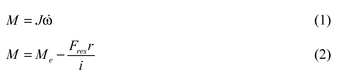
где М - ускоряющий вращающий момент, J - инерция транспортного средства, ω - частота вращения двигателя, Ме - вращающий момент маховика двигателя, Fres - сопротивление движению, r - радиус колес, i - общее передаточное число трансмиссии, m - вес транспортного средства и Ie - момент инерции двигателя; причем эти отношения выражены уравнением (4)where M is the accelerating torque, J is the inertia of the vehicle, ω is the engine speed, M e is the torque of the engine flywheel, F res is the resistance to movement, r is the radius of the wheels, i is the total gear ratio of the transmission, m is the weight of the vehicle and I e is the moment of inertia of the engine; moreover, these relations are expressed by equation (4)

что в итоге означает, чтоwhich ultimately means that

видно, что выбор передачи происходит в реальном времени посредством приведенных выше уравнений, то есть каждый раз, когда включается функция включения пониженной передачи. Расчеты предпочтительно выполняются в управляющем блоке, когда он получает указание на включение пониженной передачи, как описано выше.it can be seen that the selection of the transmission occurs in real time through the above equations, that is, each time the downshift function is turned on. The calculations are preferably carried out in the control unit when it receives an indication of the inclusion of a lower gear, as described above.
Согласно другому варианту осуществления система содержит также управляющее средство 2, выполненное с возможностью обеспечения указания того, должна ли быть включена функция включения пониженной передачи. Управляющее средство 2 предпочтительно является педалью 2 акселератора, содержащей функцию включения пониженной передачи. Как видно из фиг.3, педаль 2 акселератора может принимать множество непрерывных положений между первым крайним положением (соответствующим отсутствию приложения ускорения) и вторым крайним положением (соответствующим приложению полного ускорения). Нажимание педали акселератора в ее второе крайнее положение приведет в действие, например, нажимную кнопку или датчик 3, ведущий к включению функции включения пониженной передачи системы. Например, электрический сигнал может быть послан от кнопки или датчика 3 к управляющему блоку 110 для использования в управлении коробкой 20 передач.According to another embodiment, the system also includes control means 2, configured to provide an indication of whether the downshift function should be enabled. The control means 2 is preferably an accelerator pedal 2 comprising a downshift function. As can be seen from figure 3, the accelerator pedal 2 can take many continuous positions between the first extreme position (corresponding to the absence of acceleration application) and the second extreme position (corresponding to the full acceleration application). Pressing the accelerator pedal to its second extreme position will trigger, for example, a push button or sensor 3, leading to the inclusion of the function of turning on the low gear of the system. For example, an electrical signal may be sent from a button or sensor 3 to a
Изобретение относится также к транспортному средству 1, например грузовику или автобусу, содержащему, по меньшей мере, одну такую систему, как описанная выше.The invention also relates to a
Изобретение относится также к способу переключения передачи в коробке передач в транспортном средстве 1. Способ включает ответ на получение указания посредством выбора передачи из различных возможных передач, посредством чего двигатель 10 достигает желаемой частоты ωKD вращения за более короткое время, чем на любой другой передаче из различных возможных передач. Способ выполняет функции во всех сущностях согласно блок-схеме на фиг.4.The invention also relates to a method for shifting gears in a gearbox in a
Также следует заметить, что способ и варианты осуществления способа могут быть изменены согласно различным вариантам осуществления системы управления коробкой передач согласно изобретению.It should also be noted that the method and embodiments of the method can be changed according to various embodiments of the gearbox control system according to the invention.
Специалистам в данной области техники также будет понятно, что способ переключения передачи в коробке передач согласно настоящему изобретению также может быть осуществлен в компьютерной программе, которая при выполнении в компьютере заставляет компьютер осуществлять способ. Компьютерная программа содержится в считываемом компьютером носителе компьютерного программного продукта, который принимает форму подходящей памяти, например постоянного запоминающего устройства (ПЗУ), программируемого постоянного запоминающего устройства (ППЗУ), стираемого ППЗУ (СППЗУ), флэш-памяти, электрически программируемого ПЗУ (ЭППЗУ), жесткого диска и так далее.Those skilled in the art will also appreciate that the gear shift method in the gearbox of the present invention can also be implemented in a computer program that, when executed in a computer, causes the computer to carry out the method. The computer program is contained in a computer-readable medium of a computer program product that takes the form of a suitable memory, such as read-only memory (ROM), programmable read-only memory (EPROM), erasable EPROM (EPROM), flash memory, electrically programmable ROM (EEPROM), hard drive and so on.
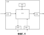
На фиг.5 схематично изображен управляющий блок 110, образующий часть системы согласно изобретению. Управляющий блок 110 содержит рассчитывающий блок 111, который может принимать форму, по существу, любого типа процессора или микропроцессора, например микросхемы для обработки цифрового сигнала (цифровой сигнальный процессор (DSP)) или микросхемы с заданной конкретной функцией (специализированная интегральная микросхема (ASIC)). Рассчитывающий блок 111 присоединен к блоку 112 памяти, который встроен в управляющий блок 110 и который предоставляет рассчитывающему блоку 111, например, хранимый код программы и/или хранимую информацию, которая требуется рассчитывающему блоку 111 для возможности осуществления расчетов. Рассчитывающий блок 111 также выполнен с возможностью хранения частичных или полных результатов расчетов в блоке 112 памяти.5 schematically shows a
Управляющий блок 110 дополнительно предусмотрен с устройствами 113, 114, 115, 116 для соответственного получения входных сигналов и посылания выходных сигналов. Эти входные и выходные сигналы могут содержать формы волны, импульсы и другие свойства, которые устройства 113, 116, получающие сигналы, могут определять как информацию и которые могут быть преобразованы в сигналы, обрабатываемые рассчитывающим блоком 111. Затем эти сигналы передаются в рассчитывающий блок 111. Устройства 114, 115, посылающие сигналы, выполнены с возможностью преобразования сигналов, полученных от рассчитывающего блока 111, для того чтобы создавать, например посредством модуляции сигналов, выходные сигналы, которые могут быть переданы к другим частям системы для определения точек включения пониженной передачи и включения повышенной передачи. Специалисту в данной области техники будет понятно, что упомянутый выше компьютер может принимать форму рассчитывающего блока 111 и что упомянутая выше память может принимать форму блока 112 памяти.The
Каждое из соединений для соответствующих устройств для соответствующего получения входных сигналов и посылания выходных сигналов может принимать форму одного или более из следующих: кабель, шина данных, например шина CAN (локальной сети контроллеров), шина передачи данных мультимедийных систем (MOST), или некоторые другие конфигурации шины, или беспроводное соединение. Соединения 70, 80, 90, 100 на фиг.1 также могут принимать форму одного или более из этих кабелей, шин или беспроводных соединений.Each of the connections for the respective devices for appropriately receiving input signals and sending output signals may take the form of one or more of the following: cable, data bus, for example CAN bus (local area network of controllers), data bus of multimedia systems (MOST), or some others bus configurations, or wireless connection. The
Наконец, настоящее изобретение не ограничено его вариантами осуществления, описанными выше, и относится к объему защиты независимого пункта прилагаемой формулы изобретения и содержит в нем все варианты осуществления.Finally, the present invention is not limited to its embodiments described above, and relates to the scope of protection of the independent claim and includes all embodiments.
Claims (14)
Тмакс.мощности=Тпереключения+Тускорения,
где Тпереключения - время, необходимое для осуществления переключения передач, а Тускорения - время, требуемое для ускорения упомянутого транспортного средства (1) до максимально мощной частоты вращения после переключения передач.8. The system according to any one of claims 1 to 3, characterized in that the transmission minimizes the time function
T max power = T switching + T acceleration ,
where T switching is the time required for gear shifting, and T acceleration is the time required to accelerate the mentioned vehicle (1) to the maximum powerful speed after gear shifting.
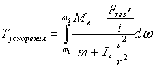
где Ме - вращающий момент маховика упомянутого двигателя (10), Ie - момент инерции упомянутого двигателя (10) и Fres, r, i и m - соответственно сопротивление движению, радиус колеса, общее передаточное число и вес транспортного средства (1).9. The system of claim 8, wherein the acceleration T is defined as
where M e is the flywheel torque of the aforementioned engine (10), I e is the moment of inertia of the aforementioned engine (10) and F res , r, i and m are the resistance to movement, the radius of the wheel, the total gear ratio and the weight of the vehicle (1) .
Applications Claiming Priority (3)
| Application Number | Priority Date | Filing Date | Title |
|---|---|---|---|
| SE0950659A SE534155C2 (en) | 2009-09-14 | 2009-09-14 | System and method for controlling a gearbox |
| SE0950659-3 | 2009-09-14 | ||
| PCT/SE2010/050963 WO2011031221A1 (en) | 2009-09-14 | 2010-09-10 | System for control of a gearbox |
Publications (2)
| Publication Number | Publication Date |
|---|---|
| RU2012114838A RU2012114838A (en) | 2013-10-27 |
| RU2525503C2 true RU2525503C2 (en) | 2014-08-20 |
Family
ID=43732684
Family Applications (1)
| Application Number | Title | Priority Date | Filing Date |
|---|---|---|---|
| RU2012114838/11A RU2525503C2 (en) | 2009-09-14 | 2010-09-10 | Transmission control system |
Country Status (7)
| Country | Link |
|---|---|
| US (1) | US9243708B2 (en) |
| EP (1) | EP2478259B1 (en) |
| CN (1) | CN102549309B (en) |
| BR (1) | BR112012004061B1 (en) |
| RU (1) | RU2525503C2 (en) |
| SE (1) | SE534155C2 (en) |
| WO (1) | WO2011031221A1 (en) |
Families Citing this family (3)
| Publication number | Priority date | Publication date | Assignee | Title |
|---|---|---|---|---|
| SE535204C2 (en) | 2009-12-17 | 2012-05-22 | Scania Cv Ab | Method for determining the driving capacity of a motor vehicle |
| CN106641225B (en) * | 2015-10-28 | 2019-02-26 | 长城汽车股份有限公司 | Shift point calibration method, device and system for automatic transmission |
| CN106402367A (en) * | 2016-11-12 | 2017-02-15 | 黄伟 | Automatic gear shifting method of electric vehicle |
Citations (3)
| Publication number | Priority date | Publication date | Assignee | Title |
|---|---|---|---|---|
| RU2080266C1 (en) * | 1990-04-04 | 1997-05-27 | Ман Нуцфарцойге АГ | Vehicle drive |
| WO2000063591A1 (en) * | 1999-04-16 | 2000-10-26 | Scania Cv Aktiebolag (Publ) | Method and apparatus for controlling an automatic gearbox |
| DE10321519A1 (en) * | 2003-05-14 | 2004-12-02 | Volkswagen Ag | Gearbox gear selection in motor vehicle involves indicating optimal gear selection suggestions for economical gear selection, selection for maximum acceleration at start of/during overtaking maneuver |
Family Cites Families (5)
| Publication number | Priority date | Publication date | Assignee | Title |
|---|---|---|---|---|
| US6067495A (en) * | 1997-06-24 | 2000-05-23 | Chrysler Corporation | Acceleration based shift strategy for an automatic transmission |
| JP2003254421A (en) * | 2002-02-28 | 2003-09-10 | Fuji Heavy Ind Ltd | Transmission control device for continuously variable transmission |
| JP4400298B2 (en) * | 2004-04-27 | 2010-01-20 | 日産自動車株式会社 | Vehicle control device |
| JP5163038B2 (en) | 2007-09-28 | 2013-03-13 | トヨタ自動車株式会社 | Control device for automatic transmission, control method, program for realizing the method, and recording medium recording the program |
| DE102008010280B4 (en) * | 2008-02-21 | 2023-02-16 | Bayerische Motoren Werke Aktiengesellschaft | Method for controlling a shifting process of automatic transmissions |
-
2009
- 2009-09-14 SE SE0950659A patent/SE534155C2/en unknown
-
2010
- 2010-09-10 EP EP10815704.1A patent/EP2478259B1/en active Active
- 2010-09-10 CN CN201080040559.7A patent/CN102549309B/en not_active Expired - Fee Related
- 2010-09-10 RU RU2012114838/11A patent/RU2525503C2/en not_active IP Right Cessation
- 2010-09-10 US US13/392,159 patent/US9243708B2/en active Active
- 2010-09-10 WO PCT/SE2010/050963 patent/WO2011031221A1/en not_active Ceased
- 2010-09-10 BR BR112012004061-8A patent/BR112012004061B1/en active IP Right Grant
Patent Citations (3)
| Publication number | Priority date | Publication date | Assignee | Title |
|---|---|---|---|---|
| RU2080266C1 (en) * | 1990-04-04 | 1997-05-27 | Ман Нуцфарцойге АГ | Vehicle drive |
| WO2000063591A1 (en) * | 1999-04-16 | 2000-10-26 | Scania Cv Aktiebolag (Publ) | Method and apparatus for controlling an automatic gearbox |
| DE10321519A1 (en) * | 2003-05-14 | 2004-12-02 | Volkswagen Ag | Gearbox gear selection in motor vehicle involves indicating optimal gear selection suggestions for economical gear selection, selection for maximum acceleration at start of/during overtaking maneuver |
Also Published As
| Publication number | Publication date |
|---|---|
| EP2478259A4 (en) | 2013-07-03 |
| CN102549309A (en) | 2012-07-04 |
| BR112012004061B1 (en) | 2020-12-01 |
| BR112012004061A2 (en) | 2016-03-08 |
| SE0950659A1 (en) | 2011-03-15 |
| SE534155C2 (en) | 2011-05-17 |
| US20120150401A1 (en) | 2012-06-14 |
| EP2478259A1 (en) | 2012-07-25 |
| US9243708B2 (en) | 2016-01-26 |
| WO2011031221A1 (en) | 2011-03-17 |
| RU2012114838A (en) | 2013-10-27 |
| EP2478259B1 (en) | 2017-03-08 |
| CN102549309B (en) | 2015-10-07 |
Similar Documents
| Publication | Publication Date | Title |
|---|---|---|
| RU2516837C2 (en) | Method of gearshift point determination | |
| US6821228B2 (en) | Control apparatus for continuously variable transmission | |
| RU2434766C2 (en) | Method of controlling automated step gearbox shifting | |
| RU2505725C2 (en) | Method of gearshift point determination | |
| CN1054343C (en) | Control system/method for self-defined starting speed ratio selection | |
| RU2525503C2 (en) | Transmission control system | |
| RU2528476C2 (en) | System for control over gearshift points | |
| US9791038B2 (en) | Control method of transmission for vehicle and control system for the same | |
| RU2509938C2 (en) | Method for determining numbers of transmission steps | |
| US20080085815A1 (en) | Method For Adapting An Operating Mode Of An Automatic Variable Speed Transmission | |
| RU2513094C2 (en) | Method of determination of gear selection steps | |
| RU2518393C2 (en) | Transmission control system | |
| US6793606B2 (en) | Shift control method for shifting an automatic transmission to a forward driving range while driving in a reverse driving range | |
| RU2540361C2 (en) | Method for determination of vehicle limit driving force | |
| US10589746B1 (en) | Declutch clunk mitigation through torque intervention | |
| RU2505726C2 (en) | Averting dual gear shifting | |
| CN104220788B (en) | For the method controlling the speed ratio shift of power unit and the system being associated | |
| EP4724721A1 (en) | Vehicle transmission control |
Legal Events
| Date | Code | Title | Description |
|---|---|---|---|
| MM4A | The patent is invalid due to non-payment of fees |
Effective date: 20160911 |