RU2525110C1 - Mechanical microwave switch - Google Patents
Mechanical microwave switch Download PDFInfo
- Publication number
- RU2525110C1 RU2525110C1 RU2013114906/08A RU2013114906A RU2525110C1 RU 2525110 C1 RU2525110 C1 RU 2525110C1 RU 2013114906/08 A RU2013114906/08 A RU 2013114906/08A RU 2013114906 A RU2013114906 A RU 2013114906A RU 2525110 C1 RU2525110 C1 RU 2525110C1
- Authority
- RU
- Russia
- Prior art keywords
- plates
- dielectric
- input
- central strip
- central
- Prior art date
Links
Images
Landscapes
- Details Of Connecting Devices For Male And Female Coupling (AREA)
Abstract
Description
Изобретение относится к технике сверхвысоких частот (СВЧ) и может быть использовано для коммутации СВЧ-сигналов в фидерных трактах различного назначения, в частности при создании переключателя фидерных трактов.The invention relates to techniques for ultra-high frequencies (microwave) and can be used for switching microwave signals in feeder paths for various purposes, in particular when creating a switch feeder paths.
При разработке устройств СВЧ возникает задача создания высокочастотного переключателя для коммутации фидерных трактов, и при этом не требуется высокое быстродействие. Для решения этой задачи часто используют механические переключатели. Механические переключатели имеют хорошее согласование, малые потери, высокий уровень рабочей мощности и малую мощность, потребляемую системой управления, так как, в отличие, например, от переключателей на полупроводниковых диодах, энергия потребляется только во время переключения.When developing microwave devices, the problem arises of creating a high-frequency switch for switching feeder paths, and high speed is not required. To solve this problem, mechanical switches are often used. Mechanical switches have good coordination, low losses, a high level of operating power and low power consumed by the control system, since, unlike, for example, switches on semiconductor diodes, energy is consumed only during switching.
Так, отдаленный аналог заявляемого изобретения - коаксиальный переключатель, содержащий установленную на торце статора переключателя входную коаксиальную фишку и расположенные по окружности статора выходные коаксиальные фишки, расположенный в роторе переключателя отрезок коаксиальной линии, изогнутой под углом 90°, причем ротор переключателя выполнен конической формы и снабжен подпружинивающим механизмом, регулирующим степень давления ротора на статор (авт.св. СССР №209553, Кл. 21а4, 72/02, 1968). Описанная конструкция позволяет добиться хорошего согласования, малых потерь и хорошего контакта в коническом переходе.So, a distant analogue of the claimed invention is a coaxial switch containing an input coaxial chip mounted on the end of the stator of the switch and output coaxial chips located around the circumference of the stator, a segment of the coaxial line bent at an angle of 90 ° located in the rotor of the switch, and the rotor of the switch is conical and equipped spring-loaded mechanism that regulates the degree of pressure of the rotor on the stator (ed. St. USSR No. 209553, Cl. 21a 4 , 72/02, 1968). The described construction allows achieving good matching, low losses and good contact in the conical transition.
Однако этому устройству присущи следующие недостатки:However, this device has the following disadvantages:
- сложность конструкции, обусловленная, например, необходимостью точного исполнения конуса ротора для обеспечения устойчивого и надежного контакта между подвижной и неподвижной частями внешнего проводника;- the complexity of the design, due, for example, the need for accurate execution of the cone of the rotor to ensure stable and reliable contact between the movable and fixed parts of the outer conductor;
- малая надежность, вызванная наличием трущихся контактов между подвижной и неподвижной частями центрального проводника коаксиальной линии;- low reliability caused by the presence of rubbing contacts between the movable and fixed parts of the central conductor of the coaxial line;
- высокая сложность изготовления контактов, обусловленная жесткими требованиями к ним, так как контакты должны обладать хорошими упругими свойствами в широком диапазоне температур, иметь небольшие размеры, чтобы не создавать дополнительных паразитных реактивностей, ухудшающих согласование, не иметь острых кромок, снижающих электропрочность устройства;- the high complexity of the manufacture of contacts due to stringent requirements for them, since the contacts must have good elastic properties in a wide temperature range, have small dimensions so as not to create additional parasitic reactances that impair coordination, and not have sharp edges that reduce the electrical strength of the device;
- малая рабочая мощность, обусловленная наличием трущихся контактов между подвижной и неподвижной частями центрального проводника коаксиальной линии. В трущихся контактах площадь соприкосновения контактных пластин подвижной части центрального проводника с ножами фидеров мала, а малая площадь соприкосновения приводит к нагреву контактов, их подгоранию, потере их пружинящих свойств, вследствие изменения при нагреве свойств материала, из которых сделаны контакты. Увеличение площади соприкосновения приводит к ухудшению согласования, росту потерь, например, за счет увеличения емкостной составляющей импеданса. Все это ограничивает рабочую мощность устройства.- low working power due to the presence of rubbing contacts between the movable and fixed parts of the central conductor of the coaxial line. In rubbing contacts, the contact area of the contact plates of the moving part of the central conductor with the feeder knives is small, and the small contact area leads to heating of the contacts, their burning, loss of their spring properties, due to a change in the properties of the material of which the contacts are made. An increase in the area of contact leads to a deterioration in coordination, an increase in losses, for example, due to an increase in the capacitive component of the impedance. All this limits the operating power of the device.
Кроме того в данном устройстве, при увеличении давления ротора на статор возможно смещение подвижной части центрального проводника таким образом, что оси центральных проводников подвижной и неподвижной частей перестанут находиться в одной плоскости, что приведет к еще большему уменьшению надежности, а при значительном расхождении осей и к ухудшению согласования.In addition, in this device, with increasing rotor pressure on the stator, it is possible to displace the movable part of the central conductor in such a way that the axes of the central conductors of the movable and fixed parts cease to be in the same plane, which will lead to an even greater decrease in reliability, and if the axes diverge significantly, worsening coordination.
Более близким аналогом, выбранным в качестве прототипа в связи со сходством выполняемой технической задачи, является контактный СВЧ переключатель на симметричной полосковой линии, содержащий ротор с центральным полоском, вращающийся в плоскости, параллельной плоскости заземляющих пластин, причем центральный полосок имеет радиус изгиба, больший радиуса ротора, и вмонтирован в диэлектрик так, что образует участок линии с диэлектрическим заполнением (авт.св. СССР №238671, Кл. 21а4, 72/02, 1969). Это устройство отличается простотой конструктивного исполнения, кроме того, в этом устройстве отсутствуют подвижные трущиеся контакты между подвижной и неподвижной частями внешнего проводника симметричной полосковой линии. Однако и этому устройству присущи те же недостатки, а именно малая надежность и малая рабочая мощность, вызванная наличием трущихся контактов между подвижной и неподвижной частями центрального проводника, низкая технологичность и высокая стоимость, обусловленная жесткими требованиями к контактным цангам.A closer analogue, selected as a prototype in connection with the similarity of the technical task being performed, is a microwave contact switch on a symmetrical strip line, containing a rotor with a central strip rotating in a plane parallel to the plane of the grounding plates, the central strip having a bending radius greater than the radius of the rotor , and mounted in a dielectric so that it forms a section of the line with dielectric filling (ed. St. USSR No. 238671, Cl. 21a 4 , 72/02, 1969). This device is characterized by simplicity of design, in addition, in this device there are no movable rubbing contacts between the movable and stationary parts of the outer conductor of the symmetrical strip line. However, this device also has the same drawbacks, namely low reliability and low working power caused by the presence of rubbing contacts between the movable and fixed parts of the central conductor, low manufacturability and high cost due to stringent requirements for contact collets.
Технический результат предлагаемого изобретения - увеличение надежности, увеличение рабочей мощности при улучшении технологичности и уменьшении стоимости.The technical result of the invention is an increase in reliability, an increase in operating power while improving manufacturability and reducing cost.
Другой технический результат - увеличение развязки.Another technical result is an increase in denouement.
Указанный технический результат достигается тем, что в механическом СВЧ переключателе, содержащем входной и выходные разъемы, центральный полосок, заземляющие пластины и диэлектрические пластины, установленные между центральным полоском и заземляющими пластинами, центральный полосок жестко связан с центральными проводниками входного и выходных разъемов, заземляющие пластины жестко связаны с внешними проводниками входного и выходных разъемов, а диэлектрические пластины выполнены подвижными и составлены, по крайней мере, из двух частей, имеющих разные эффективные диэлектрические постоянные.The specified technical result is achieved in that in a mechanical microwave switch containing input and output connectors, a central strip, grounding plates and dielectric plates installed between the central strip and grounding plates, the central strip is rigidly connected to the central conductors of the input and output connectors, grounding plates are rigidly connected to the external conductors of the input and output connectors, and the dielectric plates are movable and made up of at least two hours her having different effective dielectric constants.
Дополнительный результат достигается тем, что диэлектрические пластины, установленные между центральным полоском и заземляющими пластинами, выполнены по крайней мере, из трех составных частей, имеющие разные эффективные диэлектрические постоянные.An additional result is achieved in that the dielectric plates mounted between the center strip and the grounding plates are made of at least three components having different effective dielectric constants.
Сущность изобретения будет более понятна из приведенного описания и прилагаемых к нему чертежей, на которых изображено следующее.The invention will be more clear from the above description and the accompanying drawings, which depict the following.
На фиг.1 показана конструктивная схема предлагаемого механического СВЧ переключателя.Figure 1 shows a structural diagram of the proposed mechanical microwave switch.
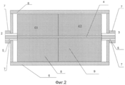
На фиг.2 показан разрез предлагаемого механического СВЧ переключателя.Figure 2 shows a section of the proposed mechanical microwave switch.
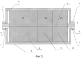
На фиг.3 показан разрез предлагаемого по п.2 механического СВЧ переключателяFigure 3 shows a section of the proposed according to claim 2 mechanical microwave switch
На чертежах и в тексте приняты следующие обозначения:In the drawings and in the text, the following notation:
1 входной разъем;1 input connector;
2, 3 выходные разъемы;2, 3 output connectors;
4 центральный полосок;4 central stripes;
5 центральные проводники входного и выходных разъемов;5 central conductors of input and output connectors;
6 заземляющие пластины;6 grounding plates;
7 внешние проводники входного и выходных разъемов;7 external conductors of input and output connectors;
8, 9, 10 - составные части диэлектрических пластин.8, 9, 10 - components of dielectric plates.
Механический СВЧ переключатель содержит входной разъем 1, выходные разъемы 2, 3, центральный полосок 4, жестко связанный с центральными проводниками 5 входного 1 и выходных разъемов 2, 3, заземляющие пластины 6, жестко связанные с внешними проводниками входного и выходных разъемов 7, и диэлектрические пластины, состоящие из двух диэлектриков 8, 9, имеющих разные эффективные диэлектрические постоянные (εэфф1 εэфф2) 5, установленные между центральным полоском 4 и заземляющими пластинами 6.A mechanical microwave switch contains an input connector 1,
Механический СВЧ переключатель работает следующим образом.Mechanical microwave switch operates as follows.
СВЧ сигнал с входа 1 поступает на центральный полосок 4, жестко связанный с центральными проводниками 5 выходных разъемов 2, 3. Конфигурация заземляющих пластин 6, диэлектрическая постоянная и размеры частей диэлектрических пластин, например, 8, подобраны таким образом, что волновое сопротивление симметричной линии (от входа 1 до выхода 2), образованной участком центрального полоска 4, заземляющими пластинами 6 и частями диэлектрических пластин 8, равно волновому сопротивлению выходного разъема 2 и присоединенному к нему ВЧ тракта.The microwave signal from input 1 enters the
Волновое сопротивление линии (от входа 1 до выхода 3), образованной участком центрального полоска 4, заземляющими пластинами 6 и частями диэлектрических пластин 9, отлично (например, больше) от волнового сопротивления выходного разъема 3 и присоединенному к нему ВЧ тракта, следовательно, СВЧ сигнал не проходит к выходному разъему 3. Таким образом, вход 1 присоединен к выходу 2, а выход 3 оказывается отключенным.The wave impedance of the line (from input 1 to output 3) formed by a section of the
Передвинув диэлектрические пластины 8,9, например, повернув их на 180° (см. Фиг.1)так, чтобы выходной разъем2 и входной разъем 1 были соединены симметричной линией, образованной участком центрального полоска 4, заземляющими пластинами 6 и частями диэлектрических пластин 9, имеющей волновое сопротивление, отличное от волнового сопротивления выходного разъема2, а выходной разъем 3 и входной разъем 1 были соединены симметричной линией, образованной участком центрального полоска 4, заземляющими пластинами 6 и частями диэлектрических пластин 8 и имеющей волновое сопротивление, равное волновому сопротивлению выходного разъема 3, подключаем к входному разъему 1 выходной разъем 3, а выходной разъем 2 отключаем от входа 1.By moving the dielectric plates 8.9, for example, rotating them through 180 ° (see FIG. 1) so that the
Из приведенного описания видно, что подвижными частями в заявляемом устройстве являются не участки центрального полоска 4, как в аналоге или в прототипе, а диэлектрические пластины, состоящие, по крайней мере, из двух диэлектриков 8, 9. Таким образом, в заявляемом устройстве отсутствуют подвижные (трущиеся) механические контакты между электропроводящими частями. Это позволяет:From the above description it is seen that the moving parts in the inventive device are not sections of the
во-первых, повысить надежность устройства, так как отсутствуют подвижные (трущиеся) механические контакты, которые вследствие механической поломки, уменьшения прижимного усилия, подгара и проч. приводят к выходу из строя всего устройства;firstly, to increase the reliability of the device, since there are no moving (rubbing) mechanical contacts, which are due to mechanical breakdown, reduction of pressing force, burning, etc. lead to the failure of the entire device;
во-вторых, увеличить рабочую мощность устройства, так как рабочая мощность определяется не размерами и свойствами контактирующих поверхностей, а свойствами ВЧ линии (размерами внутренних проводников, свойствами диэлектрика, величиной тангенса угла диэлектрических потерь, диапазоном допустимых температур и т.п.). Максимально допустимая рабочая мощность ВЧ линии, как правило, значительно превышает максимально допустимую рабочую мощность подвижных (трущихся) механических контактов.secondly, to increase the operating power of the device, since the operating power is determined not by the dimensions and properties of the contacting surfaces, but by the properties of the RF line (dimensions of the internal conductors, properties of the dielectric, value of the dielectric loss tangent, range of permissible temperatures, etc.). The maximum permissible operating power of the RF line, as a rule, significantly exceeds the maximum permissible operating power of the movable (rubbing) mechanical contacts.
Для увеличения развязки диэлектрические пластины выполнены, по крайней мере, из трех составных частей 8, 9, 10, имеющих разные эффективные диэлектрические постоянные (εэфф1 εэфф2, εэфф3,) (см. Фиг.3). Подбор соотношения диэлектрических постоянных составных частей 9,10 позволяет задать волновые сопротивления участков полосковой линии, соединяющей входной разъем 1 с выходным 2 (3) (выход 2 (3) отключен) таким образом, что ВЧ сигнал будет отражаться не только от неоднородности в месте соединения входа 1 с выходом 2(3) из-за отличного от волнового сопротивления входа 1 волнового сопротивления полосковой линии, соединяющей входной разъем 1 с отключенным выходным разъемом 2 (3), но и от неоднородности в месте стыковки составных частей 9, 10 диэлектрических пластин, имеющих различные диэлектрические постоянные, так как в этом месте происходит скачок волновых сопротивлений, вызванный различием эффективных диэлектрических постоянных (εэфф2, εэфф3) составных частей 9, 10.To increase the isolation, the dielectric plates are made of at least three
Количество составных частей, из которых составлены диэлектрические пластины, может быть различным. Увеличение количества составных частей диэлектрических пластин, имеющих разные эффективные диэлектрические постоянные (εэфф1 εэфф2), приводит за счет увеличения количества неоднородностей, от которых отражается ВЧ сигнал, к увеличению развязки.The number of components that make up the dielectric plate may vary. An increase in the number of components of dielectric plates having different effective dielectric constants (ε eff1 ε eff2 ), due to an increase in the number of inhomogeneities from which the RF signal is reflected, leads to an increase in isolation.
Предварительное макетирование показало, что механический переключатель, выполненный на симметричной полосковой линии с использованием в качестве диэлектриков материала ФЛАН-10 (диэлектрическая постоянная ε1=10) и воздуха (диэлектрическая постоянная ε2=1), может иметь КСВ не хуже 1,2 и потери СВЧ сигнала порядка 0,3 дБ, что сравнимо с параметрами механического переключателя фирмы DowKey типа 412AJ-730132, имеющего КСВ не хуже 1,25, потери 0,25 дБ, но имеющего ограничение по мощности (рабочая мощность не более 250 Вт.). Рабочая мощность предлагаемого устройства ограничивается параметрами полосковой линии. Для линии, примененной в макете переключателя (толщина центрального проводника 1 мм, расстояние между центральным полоском и заземляющими пластинами 6 мм), рабочая мощность составляет не менее 4кВт(Справочник по расчету и конструированию полосковых СВЧ устройств/ Под ред. Вольмана В.И. М.: «Радио и связь», 1982 г.)Preliminary prototyping showed that a mechanical switch made on a symmetrical strip line using FLAN-10 material (dielectric constant ε 1 = 10) and air (dielectric constant ε 2 = 1) as dielectrics can have an SWR of no worse than 1.2 and microwave signal loss of the order of 0.3 dB, which is comparable with the parameters of a mechanical switch of the DowKey type 412AJ-730132, having an SWR not worse than 1.25, loss of 0.25 dB, but having a power limit (operating power not more than 250 watts.) . The operating power of the proposed device is limited by the strip line parameters. For the line used in the model of the switch (the thickness of the central conductor is 1 mm, the distance between the central strip and the grounding plates is 6 mm), the operating power is at least 4 kW (Reference for the calculation and design of strip microwave devices / Ed. By Volman V.I. M .: “Radio and Communications, 1982)
Использование технического решения позволит увеличить надежность, повысить технологичность и уменьшить стоимость СВЧ переключателей за счет исключения неподвижных контактирующих поверхностей, а также улучшить электрические характеристики за счет использования составных диэлектрических пластин.Using a technical solution will increase reliability, improve manufacturability and reduce the cost of microwave switches by eliminating fixed contact surfaces, as well as improve electrical performance through the use of composite dielectric plates.
Claims (2)
Priority Applications (1)
| Application Number | Priority Date | Filing Date | Title |
|---|---|---|---|
| RU2013114906/08A RU2525110C1 (en) | 2013-04-02 | 2013-04-02 | Mechanical microwave switch |
Applications Claiming Priority (1)
| Application Number | Priority Date | Filing Date | Title |
|---|---|---|---|
| RU2013114906/08A RU2525110C1 (en) | 2013-04-02 | 2013-04-02 | Mechanical microwave switch |
Publications (1)
| Publication Number | Publication Date |
|---|---|
| RU2525110C1 true RU2525110C1 (en) | 2014-08-10 |
Family
ID=51355225
Family Applications (1)
| Application Number | Title | Priority Date | Filing Date |
|---|---|---|---|
| RU2013114906/08A RU2525110C1 (en) | 2013-04-02 | 2013-04-02 | Mechanical microwave switch |
Country Status (1)
| Country | Link |
|---|---|
| RU (1) | RU2525110C1 (en) |
Cited By (2)
| Publication number | Priority date | Publication date | Assignee | Title |
|---|---|---|---|---|
| RU2598180C1 (en) * | 2015-07-24 | 2016-09-20 | Акционерное общество "Научно-производственное объединение "Лианозовский электромеханический завод" (АО НПО "ЛЭМЗ") | Mechanical microwave switch |
| RU187676U1 (en) * | 2018-06-04 | 2019-03-14 | Российская Федерация, от имени которой выступает Министерство обороны Российской Федерации | MICROWAVE MATRIX SWITCH |
Citations (5)
| Publication number | Priority date | Publication date | Assignee | Title |
|---|---|---|---|---|
| RU2020659C1 (en) * | 1990-05-18 | 1994-09-30 | Саратовский государственный университет | Microwave switch |
| US5936493A (en) * | 1997-11-24 | 1999-08-10 | Raytheon Company | Low cost, one-shot switch waveguide window |
| US6483393B1 (en) * | 2001-08-23 | 2002-11-19 | Hoton How | Method and apparatus of obtaining phase shift using nonreciprocal resonator |
| US6593833B2 (en) * | 2001-04-04 | 2003-07-15 | Mcnc | Tunable microwave components utilizing ferroelectric and ferromagnetic composite dielectrics and methods for making same |
| US7042305B2 (en) * | 2002-12-20 | 2006-05-09 | Com Dev Ltd. | Transmission line termination |
-
2013
- 2013-04-02 RU RU2013114906/08A patent/RU2525110C1/en not_active IP Right Cessation
Patent Citations (5)
| Publication number | Priority date | Publication date | Assignee | Title |
|---|---|---|---|---|
| RU2020659C1 (en) * | 1990-05-18 | 1994-09-30 | Саратовский государственный университет | Microwave switch |
| US5936493A (en) * | 1997-11-24 | 1999-08-10 | Raytheon Company | Low cost, one-shot switch waveguide window |
| US6593833B2 (en) * | 2001-04-04 | 2003-07-15 | Mcnc | Tunable microwave components utilizing ferroelectric and ferromagnetic composite dielectrics and methods for making same |
| US6483393B1 (en) * | 2001-08-23 | 2002-11-19 | Hoton How | Method and apparatus of obtaining phase shift using nonreciprocal resonator |
| US7042305B2 (en) * | 2002-12-20 | 2006-05-09 | Com Dev Ltd. | Transmission line termination |
Cited By (2)
| Publication number | Priority date | Publication date | Assignee | Title |
|---|---|---|---|---|
| RU2598180C1 (en) * | 2015-07-24 | 2016-09-20 | Акционерное общество "Научно-производственное объединение "Лианозовский электромеханический завод" (АО НПО "ЛЭМЗ") | Mechanical microwave switch |
| RU187676U1 (en) * | 2018-06-04 | 2019-03-14 | Российская Федерация, от имени которой выступает Министерство обороны Российской Федерации | MICROWAVE MATRIX SWITCH |
Similar Documents
| Publication | Publication Date | Title |
|---|---|---|
| CN101689735B (en) | Coaxial connector | |
| CN101420091B (en) | High-frequency coaxial connector | |
| TWI518995B (en) | The diversity antenna combination and its dynamic adjustment of the input impedance are wide Frequency antenna | |
| RU2525110C1 (en) | Mechanical microwave switch | |
| TW201436368A (en) | Tunable antenna | |
| Datta et al. | Design of broadband power divider based on substrate-integrated waveguide technology | |
| CN109962373A (en) | Electric connector | |
| CN210778914U (en) | Central conductor and miniaturized circulator | |
| RU2509395C1 (en) | Contact microwave switch | |
| CN201518375U (en) | High-frequency coaxial connector | |
| CN112166526B (en) | Method for controlling transmission of electromagnetic wave based on light and apparatus therefor | |
| KR101401251B1 (en) | A phase shifter using metamaterial transmission line unit cells | |
| RU2683000C1 (en) | Multichannel rotary joint | |
| KR101489214B1 (en) | Coaxial cable | |
| US2597867A (en) | High-frequency attenuating device | |
| RU2598180C1 (en) | Mechanical microwave switch | |
| RU2438214C1 (en) | MICROSTRIP p-i-n-DIODE MICROWAVE SWITCH | |
| CN112216937B (en) | Faraday rotary switch | |
| RU2671339C1 (en) | Hitless super-high-frequency switch for two positions | |
| CN107689471A (en) | A kind of Finline switched feed circuits | |
| RU2456719C1 (en) | Selective protection device on reciprocal rods | |
| CN207303527U (en) | QP is from correcting blind-mating connector | |
| RU2406187C1 (en) | Super-high frequency switchboard | |
| RU2625251C1 (en) | Omnidirectional annular antenna | |
| RU156173U1 (en) | SELECTIVE PROTECTION DEVICE ON COLLECTIVE RODS |
Legal Events
| Date | Code | Title | Description |
|---|---|---|---|
| MM4A | The patent is invalid due to non-payment of fees |
Effective date: 20190403 |