RU2521489C2 - Efficient filter weight computation for mimo system - Google Patents
Efficient filter weight computation for mimo system Download PDFInfo
- Publication number
- RU2521489C2 RU2521489C2 RU2010110954/07A RU2010110954A RU2521489C2 RU 2521489 C2 RU2521489 C2 RU 2521489C2 RU 2010110954/07 A RU2010110954/07 A RU 2010110954/07A RU 2010110954 A RU2010110954 A RU 2010110954A RU 2521489 C2 RU2521489 C2 RU 2521489C2
- Authority
- RU
- Russia
- Prior art keywords
- matrix
- channel response
- spatial filter
- equation
- row vector
- Prior art date
Links
Images


Classifications
-
- H—ELECTRICITY
- H04—ELECTRIC COMMUNICATION TECHNIQUE
- H04B—TRANSMISSION
- H04B7/00—Radio transmission systems, i.e. using radiation field
- H04B7/02—Diversity systems; Multi-antenna system, i.e. transmission or reception using multiple antennas
- H04B7/04—Diversity systems; Multi-antenna system, i.e. transmission or reception using multiple antennas using two or more spaced independent antennas
- H04B7/0413—MIMO systems
-
- H—ELECTRICITY
- H04—ELECTRIC COMMUNICATION TECHNIQUE
- H04B—TRANSMISSION
- H04B7/00—Radio transmission systems, i.e. using radiation field
- H04B7/02—Diversity systems; Multi-antenna system, i.e. transmission or reception using multiple antennas
- H04B7/04—Diversity systems; Multi-antenna system, i.e. transmission or reception using multiple antennas using two or more spaced independent antennas
- H04B7/08—Diversity systems; Multi-antenna system, i.e. transmission or reception using multiple antennas using two or more spaced independent antennas at the receiving station
- H04B7/0837—Diversity systems; Multi-antenna system, i.e. transmission or reception using multiple antennas using two or more spaced independent antennas at the receiving station using pre-detection combining
- H04B7/0842—Weighted combining
- H04B7/0848—Joint weighting
- H04B7/0854—Joint weighting using error minimizing algorithms, e.g. minimum mean squared error [MMSE], "cross-correlation" or matrix inversion
-
- H—ELECTRICITY
- H04—ELECTRIC COMMUNICATION TECHNIQUE
- H04L—TRANSMISSION OF DIGITAL INFORMATION, e.g. TELEGRAPHIC COMMUNICATION
- H04L1/00—Arrangements for detecting or preventing errors in the information received
- H04L1/02—Arrangements for detecting or preventing errors in the information received by diversity reception
-
- H—ELECTRICITY
- H04—ELECTRIC COMMUNICATION TECHNIQUE
- H04L—TRANSMISSION OF DIGITAL INFORMATION, e.g. TELEGRAPHIC COMMUNICATION
- H04L25/00—Baseband systems
- H04L25/02—Details ; arrangements for supplying electrical power along data transmission lines
- H04L25/0202—Channel estimation
- H04L25/024—Channel estimation channel estimation algorithms
- H04L25/0242—Channel estimation channel estimation algorithms using matrix methods
- H04L25/0248—Eigen-space methods
-
- H—ELECTRICITY
- H04—ELECTRIC COMMUNICATION TECHNIQUE
- H04L—TRANSMISSION OF DIGITAL INFORMATION, e.g. TELEGRAPHIC COMMUNICATION
- H04L25/00—Baseband systems
- H04L25/02—Details ; arrangements for supplying electrical power along data transmission lines
- H04L25/03—Shaping networks in transmitter or receiver, e.g. adaptive shaping networks
- H04L25/03006—Arrangements for removing intersymbol interference
- H04L2025/0335—Arrangements for removing intersymbol interference characterised by the type of transmission
- H04L2025/03426—Arrangements for removing intersymbol interference characterised by the type of transmission transmission using multiple-input and multiple-output channels
-
- H—ELECTRICITY
- H04—ELECTRIC COMMUNICATION TECHNIQUE
- H04L—TRANSMISSION OF DIGITAL INFORMATION, e.g. TELEGRAPHIC COMMUNICATION
- H04L25/00—Baseband systems
- H04L25/02—Details ; arrangements for supplying electrical power along data transmission lines
- H04L25/03—Shaping networks in transmitter or receiver, e.g. adaptive shaping networks
- H04L25/03006—Arrangements for removing intersymbol interference
- H04L2025/03592—Adaptation methods
- H04L2025/03598—Algorithms
- H04L2025/03605—Block algorithms
-
- H—ELECTRICITY
- H04—ELECTRIC COMMUNICATION TECHNIQUE
- H04L—TRANSMISSION OF DIGITAL INFORMATION, e.g. TELEGRAPHIC COMMUNICATION
- H04L25/00—Baseband systems
- H04L25/02—Details ; arrangements for supplying electrical power along data transmission lines
- H04L25/03—Shaping networks in transmitter or receiver, e.g. adaptive shaping networks
- H04L25/03006—Arrangements for removing intersymbol interference
- H04L2025/03592—Adaptation methods
- H04L2025/03598—Algorithms
- H04L2025/03611—Iterative algorithms
-
- H—ELECTRICITY
- H04—ELECTRIC COMMUNICATION TECHNIQUE
- H04L—TRANSMISSION OF DIGITAL INFORMATION, e.g. TELEGRAPHIC COMMUNICATION
- H04L25/00—Baseband systems
- H04L25/02—Details ; arrangements for supplying electrical power along data transmission lines
- H04L25/0202—Channel estimation
- H04L25/024—Channel estimation channel estimation algorithms
- H04L25/0242—Channel estimation channel estimation algorithms using matrix methods
- H04L25/0246—Channel estimation channel estimation algorithms using matrix methods with factorisation
Landscapes
- Engineering & Computer Science (AREA)
- Computer Networks & Wireless Communication (AREA)
- Signal Processing (AREA)
- Physics & Mathematics (AREA)
- Mathematical Physics (AREA)
- Power Engineering (AREA)
- Radio Transmission System (AREA)
- Complex Calculations (AREA)
- Mobile Radio Communication Systems (AREA)
- Filters That Use Time-Delay Elements (AREA)
- Image Processing (AREA)
Abstract
Description
Область техники, к которой относится изобретениеFIELD OF THE INVENTION
Изобретение, в общем, относится к области связи и, более конкретно, к методикам расчета весовых коэффициентов фильтров в системе связи.The invention, in General, relates to the field of communication and, more specifically, to methods for calculating the weighting coefficients of filters in a communication system.
Уровень техникиState of the art
В системе связи с множеством входов и множеством выходов (MIMO, МВМВ) для передачи данных используется множество (T) передающих антенн передающей станции и множество (R) приемных антенн приемной станции. Канал MIMO, формируемый T передающими антеннами и R приемными антеннами, может быть разложен на S пространственных каналов, где S≤min {T, R}. S пространственных каналов можно использовать для передачи данных таким образом, чтобы достичь большей общей пропускной способности и/или более высокой надежности.In a communication system with multiple inputs and multiple outputs (MIMO, MIMO), a plurality of (T) transmit antennas of a transmitting station and a plurality of (R) receive antennas of a receiving station are used for data transmission. The MIMO channel formed by T transmit antennas and R receive antennas can be decomposed into S spatial channels, where S≤min {T, R}. S spatial channels can be used to transmit data in such a way as to achieve greater overall throughput and / or higher reliability.
Передающая станция может одновременно передавать T потоков данных через T передающих антенн. В этих потоках данных возникают искажения в соответствии с откликом канала MIMO, и их качество дополнительно ухудшается в результате воздействия шумов и взаимных помех. Приемная станция принимает передаваемые потоки данных через R приемных антенн. Принимаемый сигнал от каждой приемной антенны содержит масштабированную версию T потоков данных, переданных передающей станцией. Переданные потоки данных, таким образом, диспергированы среди R сигналов, принятых через R приемных антенн. Приемная станция затем выполняет пространственную обработку приемника для R принятых сигналов, используя матрицу пространственного фильтра, для восстановления переданных потоков данных.A transmitting station can simultaneously transmit T data streams through T transmit antennas. In these data streams, distortions occur in accordance with the response of the MIMO channel, and their quality is further deteriorated by noise and interference. A receiving station receives transmitted data streams through R receiving antennas. The received signal from each receiving antenna contains a scaled version of T data streams transmitted by the transmitting station. The transmitted data streams are thus dispersed among the R signals received through the R receive antennas. The receiving station then performs receiver spatial processing for the R received signals using the spatial filter matrix to recover the transmitted data streams.
Определение весовых коэффициентов матрицы пространственного фильтра требует объемной обработки. Это связано с тем, что матрицу пространственного фильтра обычно получают на основе функции, которая содержит обращение матрицы, и прямые расчеты обращения матрицы требуют объемных вычислений.Determining the weighting coefficients of a spatial filter matrix requires volumetric processing. This is due to the fact that the spatial filter matrix is usually obtained on the basis of a function that contains the matrix inversion, and direct calculations of the matrix inversion require volumetric calculations.
Таким образом, в данной области техники требуется разработка методики для эффективного расчета весовых коэффициентов фильтра.Thus, in the art it is necessary to develop a methodology for efficiently calculating filter weights.
Сущность изобретенияSUMMARY OF THE INVENTION
Здесь описаны методики эффективного расчета весовых коэффициентов матрицы пространственного фильтра. Эти методики позволяют исключить непосредственный расчет обращения матрицы.Techniques for efficiently calculating weight coefficients of a spatial filter matrix are described herein. These techniques eliminate the direct calculation of matrix inversion.
В первом варианте воплощения для получения матрицы М пространственного фильтра Эрмитову матрицу P итерационно получают на основе матрицы H отклика канала, и обращение матрицы опосредованно рассчитывают путем итерационного получения Эрмитовой матрицы. Эрмитова матрица может быть инициализирована до единичной матрицы. Одну итерацию затем выполняют для каждой строки матрицы отклика канала, и эффективную последовательность расчетов выполняют для каждой итерации. Для i-й итерации получают промежуточный вектор a i строки на основе вектора h i отклика канала, который представляет собой i-ю строку матрицы отклика канала. Скалярное значение r i получают на основе промежуточного вектора строки и вектора строки отклика канала. Промежуточную матрицу C i также получают на основе промежуточного вектора строки. Эрмитову матрицу затем обновляют на основе скалярного значения и промежуточной матрицы. После окончания всех итераций, получают матрицу пространственного фильтра на основе Эрмитовой матрицы и матрицы отклика канала. In the first embodiment, to obtain the spatial filter matrix M, the Hermitian matrix P is iteratively obtained based on the channel response matrix H , and the matrix inversion is indirectly calculated by iteratively obtaining the Hermitian matrix. Hermitian matrix can be initialized to a single matrix. One iteration is then performed for each row of the channel response matrix, and an effective calculation sequence is performed for each iteration. For the i-th iteration, an intermediate row vector a i is obtained based on the channel response vector h i , which is the i-th row of the channel response matrix. The scalar value r i is obtained based on the intermediate line vector and the channel response line vector. An intermediate matrix C i is also obtained based on the intermediate row vector. The Hermitian matrix is then updated based on the scalar value and the intermediate matrix. After all iterations are completed, a spatial filter matrix is obtained based on the Hermitian matrix and the channel response matrix.
Во втором варианте воплощения выполняют множество поворотов для итерационного получения первый матрицы P 1/2 и второй матрицы B для псевдообращенной матрицы отклика канала. Одну итерацию выполняют для каждой строки матрицы отклика канала. Для каждой итерации формируют матрицу Y, содержащую первую и вторую матрицы из предыдущей итерации. Множество поворотов Гивенса затем выполняют для матрицы Y для обнуления элементов в первой строке матрицы, для получения обновленных первой и второй матриц для следующей итерации. После того как все итерации будут закончены, получают матрицу пространственного фильтра на основе первой и второй матриц.In the second embodiment, many rotations are performed to iteratively obtain the first matrix P 1/2 and the second matrix B for the pseudoinverse channel response matrix. One iteration is performed for each row of the channel response matrix. For each iteration, a matrix Y is formed containing the first and second matrices from the previous iteration. Many turns of Givens are then performed for matrix Y to zero out the elements in the first row of the matrix to obtain updated first and second matrices for the next iteration. After all iterations are completed, a spatial filter matrix is obtained based on the first and second matrices.
В третьем варианте воплощения формируют матрицу X на основе матрицы отклика канала и разлагают (например, с использованием разложения по собственным значениям), для получения унитарной матрицы V и диагональной матрицы Λ. Разложение может быть получено в результате итерационного выполнения поворотов Якоби для матрицы X. Матрицу пространственного фильтра затем получают на основе унитарной матрицы, диагональной матрицы и матрицы отклика канала.In the third embodiment, a matrix X is formed based on the channel response matrix and decomposed (for example, using eigenvalue decomposition) to obtain a unitary matrix V and a diagonal matrix Λ . The decomposition can be obtained by iteratively performing Jacobi rotations for matrix X. The spatial filter matrix is then obtained based on the unitary matrix, the diagonal matrix, and the channel response matrix.
Различные аспекты и варианты выполнения изобретения более подробно описаны ниже.Various aspects and embodiments of the invention are described in more detail below.
Краткое описание чертежейBrief Description of the Drawings
Свойства и сущность настоящего изобретения будут более понятны из подробного описания, приведенного ниже, которое следует рассматривать совместно с чертежами, на которых одинаковыми номерами ссылочных позиций обозначены соответствующие элементы на всех чертежах.The properties and essence of the present invention will be better understood from the detailed description below, which should be read in conjunction with the drawings, in which the same reference numerals denote the corresponding elements in all the drawings.
На фиг.1, 2 и 3 представлены процессы, выполняемые для расчета матрицы пространственного фильтра MMSE (МСКО, минимальная среднеквадратическая ошибка), на основе первого, второго и третьего вариантов воплощения, соответственно.1, 2 and 3 show the processes performed to calculate the spatial filter matrix MMSE (ISCED, the minimum standard error), based on the first, second and third embodiments, respectively.
На фиг.4 показана блок-схема точки доступа и терминала пользователя.Figure 4 shows a block diagram of an access point and a user terminal.
Подробное описание изобретенияDETAILED DESCRIPTION OF THE INVENTION
Слово "примерный", используемое здесь, означает "используемый в качестве примера, случая или иллюстрации". Любой вариант выполнения или конструкция, описанный здесь как "примерный", необязательно следует рассматривать как предпочтительный или преимущественный по сравнению с другими вариантами выполнения или конструкциями.The word “exemplary,” as used herein, means “used as an example, occasion, or illustration.” Any embodiment or design described herein as “exemplary” is not necessarily to be construed as preferred or advantageous over other embodiments or designs.
Описанные здесь методики расчета весовых коэффициентов фильтра можно использовать для системы MIMO с одной несущей и системы MIMO с множеством несущих. Множество несущих могут быть получены с использованием мультиплексирования с ортогональным частотным разделением сигналов (OFDM), при множественном доступе с разделением частот с перемежением (IFDMA), локализованном множественном доступе с разделением частот (LFDMA), или некоторой другой методики модуляции. OFDM, IFDMA и LFDMA эффективно разделяют общую полосу пропускания системы на множество (K) ортогональных частотных подполос, которые также называются тонами, поднесущими, элементами сигнала и частотными каналами. Каждую подполосу ассоциируют с соответствующей поднесущей, которая может быть модулирована данными. В системе OFDM символы модуляции передают в области частот для всех или поднабора K подполос. В IFDMA передают символы модуляции в области времени по подполосам, которые равномерно распределены по K подполосам. В LFDMA передают символы модуляции в области времени и обычно в соседних подполосах. Для ясности большая часть следующего описания направлена на систему MIMO с одной несущей, в которой используется одна поднесущая.The techniques for calculating filter weights described herein can be used for a single-carrier MIMO system and a multi-carrier MIMO system. Multiple carriers may be obtained using orthogonal frequency division multiplexing (OFDM), interleaved multiple access (IFDMA), localized frequency division multiple access (LFDMA), or some other modulation technique. OFDM, IFDMA, and LFDMA effectively divide the overall system bandwidth into multiple (K) orthogonal frequency subbands, which are also called tones, subcarriers, signal elements, and frequency channels. Each subband is associated with a corresponding subcarrier that can be modulated with data. In the OFDM system, modulation symbols are transmitted in the frequency domain for all or a subset of K subbands. IFDMA transmits modulation symbols in the time domain into subbands that are evenly distributed across K subbands. In LFDMA, modulation symbols are transmitted in the time domain and usually in adjacent subbands. For clarity, much of the following description is directed to a single-carrier MIMO system that uses a single sub-carrier.
Канал MIMO, сформированный множеством (T) передающих антенн в передающей станции и множеством ® приемных антенн в приемной станции, может характеризоваться матрицей H отклика канала размером RxT, которая может быть задана как:A MIMO channel formed by a plurality of (T) transmit antennas at a transmitting station and a plurality of ® receive antennas at a receiving station may be characterized by a channel response matrix H of size RxT, which may be defined as:

Уравнение (1)Equation (1)
где hi,j , для i=1,...,R и j=1,...,T обозначает усиление связи или комплексное усиление канала между передающей антенной j и приемной антенной i; иwhere hi, j ,for i = 1, ..., R and j = 1, ..., T denotes communication gain or complex channel gain between transmitting antenna j and receiving antenna i; and
h i представляет собой вектор строки отклика канала размером 1×T для приемной антенны i, который представляет собой i-ю строку матрицы H. h i is the 1 × T channel response line vector for the receiving antenna i , which is the i-th row of the matrix H.
Для простоты в следующем описании предполагается, что канал MIMO имеет полный ранг и, что количество пространственных каналов (S) задается как: S=T≤R.For simplicity, the following description assumes that the MIMO channel has a full rank and that the number of spatial channels (S) is specified as: S = T≤R.
Передающая станция может передавать T символов модуляции одновременно через T передающих антенн в каждый период символа. Передающая станция может выполнять или может не выполнять пространственную обработку для символов модуляции перед передачей. Для простоты в следующем описании предполагается, что каждый символ модуляции передают через передающую антенну без какой-либо пространственной обработки.A transmitting station may transmit T modulation symbols simultaneously through T transmit antennas in each symbol period. The transmitting station may or may not perform spatial processing for modulation symbols before transmission. For simplicity, the following description assumes that each modulation symbol is transmitted through a transmit antenna without any spatial processing.
Приемная станция получает R принятых символов из R приемных антенн в каждый период символа. Принятые символы могут быть выражены как:The receiving station receives R received symbols from R receiving antennas in each symbol period. Accepted characters can be expressed as:
![]()
![]()
Уравнение (2)Equation (2)
где s представляет собой вектор размером T×1, в котором T символов модуляции переданы передающей станцией;where s is a T × 1 vector in which T modulation symbols are transmitted by a transmitting station;
r представляет собой вектор размером R×1, где R принимаемых символов получают в приемной станции через R приемных антенн; и r is an R × 1 vector, where R received symbols are received at the receiving station via R receiving antennas; and
n представляет собой вектор шумов размером R×1. n is a noise vector of size R × 1.
Для простоты можно предположить, что шумы представляют собой аддитивный белый Гауссов шум (AWGN) с нулевым средним вектором и матрицей ковариации δ2 n×I, где δ2 n представляет собой дисперсию шума и I представляет собой единичную матрицу.For simplicity, we can assume that the noises are additive white Gaussian noise (AWGN) with zero mean vector and covariance matrix δ2 n×Iwhere δ2 n represents a noise variance andI is a unit matrix.
В приемной станции могут использоваться различные методики пространственной обработки для восстановления символов модуляции, переданных передающей станцией. Например, приемная станция может выполнять пространственную обработку приемника с минимальной среднеквадратичной ошибкой (MMSE), следующим образом:At the receiving station, various spatial processing techniques may be used to recover modulation symbols transmitted by the transmitting station. For example, a receiving station may perform receiver spatial processing with a minimum mean square error (MMSE) as follows:
![]()
![]()
Уравнение (3) Equation (3)
где M представляет собой матрицу пространственного фильтра MMSE размером T×R;where M is an MMSE spatial filter matrix of size T × R;
P представляет собой Эрмитову матрицу ковариации размером T×T для ошибки оценки s-![]()
![]()
![]()
![]()
" H " обозначает сопряженную перестановку. “ H ” stands for conjugate permutation.
Матрица P ковариации может быть задана как P=E[(s-![]()
![]()
![]()
![]()
Как показано в уравнении (3), матрица М пространственного фильтра MMSE имеет расчет обращенной матрицы. Прямой расчет обращения матрицы требует выполнения большого объема компьютерных операций. Матрица пространственного фильтра MMSE может быть более эффективно получена на основе вариантов выполнения, описанных ниже, которые позволяют опосредованно рассчитывать обращение матрицы с использованием итеративного процесса, вместо непосредственного расчета обращения матрицы.As shown in equation (3), the MMSE spatial filter matrix M has an inverse matrix calculation. Direct calculation of matrix inversion requires a large amount of computer operations. The spatial filter matrix MMSE can be more efficiently obtained based on the embodiments described below, which allow indirect calculation of matrix inversion using an iterative process, instead of directly calculating matrix inversion.
В первом варианте воплощения расчета матрицы М пространственного фильтра MMSE рассчитывают Эрмитову матрицу P на основе уравнении Риккати. Эрмитова матрица P может быть выражена следующим образом:In a first embodiment of the calculation of the MMSE spatial filter matrix M, the Hermitian matrix P is calculated based on the Riccati equation. The Hermitian matrix P can be expressed as follows:

Уравнение (4)Equation (4)
Эрмитова матрица P i размером TxT может быть определена как:The Hermitian matrix P i of size TxT can be defined as:

Уравнение (5)Equation (5)
Лемма обращения матрицы может быть применена к уравнению (5) для получения следующего:The matrix inversion lemma can be applied to equation (5) to obtain the following:

Уравнение (6) Equation (6)
где r i представляет собой скалярную действительную величину. Уравнение (6) называется уравнением Риккати. Матрица P i может быть инициализирована как P 0=![]()
![]()
Уравнение (6) может быть перемножено на определенные коэффициенты для получения следующего:Equation (6) can be multiplied by certain coefficients to obtain the following:

Уравнение (7)Equation (7)
где матрицу P i инициализируют как P 0=I, и матрицу P получают как P=![]()
![]()
![]()
![]()
Каждая итерация уравнения (7) может быть выполнена следующим образом:Each iteration of equation (7) can be performed as follows:
![]()
![]()
Уравнение (8a)Equation (8a)
![]()
![]()
Уравнение (8b)Equation (8b)
![]()
![]()
Уравнение (8c)Equation (8c)
![]()
![]()
Уравнение (8d)Equation (8d)
где a i представляет собой вектор промежуточной строки размером 1×T элементов с комплексным значением; и where a i is an intermediate row vector of 1 × T elements with a complex value; and
C представляет собой промежуточную Эрмитову матрицу размером T×T. C is an intermediate Hermitian matrix of size T × T.
В системе (8) уравнений последовательность операций структурирована для эффективного расчета с помощью аппаратных средств. Скалярное значение ri рассчитывают перед матрицей C i. Разделение по ri в уравнении (7) достигается с помощью обращения и умножения. Обращение ri может быть выполнено параллельно с расчетом C i. Обращение ri достигается со сдвигом для нормализации ri и с применением справочной таблицы для получения обращенного значения ri. Нормализация ri может быть компенсирована умножением на C i.In the system of equations (8), the sequence of operations is structured for efficient calculation using hardware. The scalar value r i is calculated before the matrix C i . Separation by r i in equation (7) is achieved by inversion and multiplication. The circulation of r i can be performed in parallel with the calculation of C i . Inversion of r i is achieved with a shift to normalize r i and using the lookup table to obtain the inverse of r i . Normalization r i can be compensated by multiplying by C i .
Матрицу P i инициализируют как Эрмитову матрицу или P 0=I, и она остается Эрмитовой матрицей во всех следующих итерациях. Следовательно, только верхнюю (или нижнюю) диагональную матрицу требуется рассчитывать для каждой итерации. После окончания R итераций получают матрицу P, как P=![]()
![]()

Уравнение (9)Equation (9)
На фиг.1 показан процесс 100 расчета матрицы M пространственного фильтра MMSE, основанной на первом варианте воплощения. Матрица P i инициализирована как P 0=1 (блок 112), и индекс i используется для обозначения номера итерации, инициализируется как i=1 (блок 114). Затем выполняют R итераций уравнения Риккати.1, a
Каждую итерацию уравнения Риккати выполняют с помощью блока 120. Для i-й итерации вектор a i промежуточной строки рассчитывают на основе заявленного вектора h i отклика канала и Эрмитовой матрицы P i+1 предшествующей итерации, как показано в уравнении (8a) (блок 122). Скалярное значение ri рассчитывают на основе дисперсии δ 2 n шумов, вектора a i промежуточной строки и вектора h i строки отклика канала, как показано в уравнении (8b) (блок 124). Скалярная величина r i после этого становится обращенной (блок 126). Промежуточную матрицу C i рассчитывают на основе a i промежуточной строки, как показано в уравнении (8c) (блок 128). Матрицу P i затем обновляют на основе инвертированной скалярной величины r i и промежуточной матрицы C i, как показано в уравнении (8d) (блок 130).Each iteration of the Riccati equation is performed using
Затем определяют, были ли выполнены все R итераций (блок 132). В случае отрицательного ответа, выполняют последовательное приращение индекса i (блок 134), и процесс возвращается к блоку 122 для выполнения другой итерации. В противном случае, если все R итераций были выполнены, рассчитывают матрицу М пространственного фильтра MMSE на основе Эрмитовой матрицы P R для последней итерации, матрицы H отклика каналов и дисперсии δ 2 n шумов, как показано в уравнении (9) (блок 136). Матрицу М затем можно использовать для пространственной обработки приемника, как показано в уравнении (3).It is then determined whether all R iterations have been performed (block 132). In the case of a negative answer, perform a sequential increment of the index i (block 134), and the process returns to block 122 to perform another iteration. Otherwise, if all R iterations have been performed, the MMSE spatial filter matrix M is calculated based on the Hermitian matrixP R for the last iteration, the matricesH channel response and dispersionδ 2 n noise as shown in equation (9) (block 136). MatrixM then can be used for spatial processing of the receiver, as shown in equation (3).
Во втором варианте воплощения расчета матрицы М пространственного фильтра MMSE определяют Эрмитову матрицу P путем получения квадратного корня P, который представляет собой P 1/2, на основе итерационной процедуры. Пространственная обработка приемника в уравнении (3) может быть выражена следующим образом:In a second embodiment of the calculation of the MMSE spatial filter matrix M , the Hermitian matrix P is determined by obtaining the square root of P , which is P 1/2 , based on an iterative procedure. The spatial processing of the receiver in equation (3) can be expressed as follows:
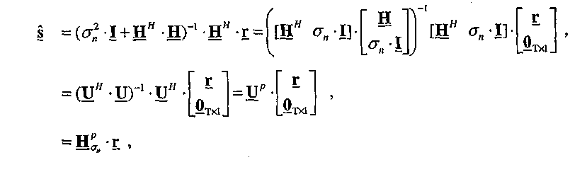
Уравнение (10) Equation (10)
где U=
U p представляет собой псевдообращенную матрицу размером T×(R+T), полученную в результате операции обращения или псевдообращения Мура-Пенроуза для U, или U p=(U H ∙ U)-1 ∙ U H; U p is a pseudo-inverse matrix of size T × (R + T) obtained as a result of the inversion or pseudo-inversion of Moore-Penrose for U , or U p = ( U H ∙ U ) -1 ∙ U H ;
0 Tx1 представляет собой вектор размером T×1, содержащий одни нули; и 0 Tx1 is a vector of size T × 1 containing one zeros; and
H p δn представляет собой подматрицу размером T×R, содержащую первые R столбцов U p. H p δn is a T × R submatrix containing the first R columns of U p .
Разложение QR может быть выполнено для матрицы с дополненным каналом следующим образом:QR decomposition can be performed for a matrix with augmented channel as follows:

Уравнение (11) Equation (11)
где Q представляет собой матрицу размером (R+T)×T с ортонормированными столбцами;where Q is a matrix of size (R + T) × T with orthonormal columns;
R представляет собой матрицу размером T×T, которая не является единичной матрицей; R is a matrix of size T × T, which is not a unit matrix;
B представляет собой матрицу размером R×T, содержащую первые R строк матрицы Q; и B is an R × T matrix containing the first R rows of the matrix Q ; and
Q 2 представляет собой матрицу размером T×T, содержащую последние T строк матрицы Q. Q 2 is a T × T matrix containing the last T rows of Q.
QR (КО, квазиобращенное) разложение в уравнении (11) разлагает матрицу дополненного канала на ортогональную матрицу Q и на не единичную матрицу R. Ортогональная матрица Q имеет следующее свойство: Q H•Q=I, что означает, что столбцы ортогональной матрицы являются ортогональными относительно друг друга, и каждый столбец имеет единичную степень. Не единичная матрица представляет собой матрицу, для которой может быть рассчитана обращенная матрица.The QR (KO, quasi-inverse) decomposition in equation (11) decomposes the augmented channel matrix into an orthogonal matrix Q and into a non-identity matrix R. The orthogonal matrix Q has the following property: Q H • Q = I , which means that the columns of the orthogonal matrix are orthogonal with respect to each other, and each column has a unit degree. A non-identity matrix is a matrix for which an inverse matrix can be calculated.
Эрмитова матрица P может быть затем выражена как:The Hermitian matrix P can then be expressed as:

Уравнение (12)Equation (12)
R представляет собой разложение Колецкого или квадратный корень матрицы P-1. Следовательно, P 1/2 равно R -1 и называется квадратным корнем матрицы P. R is the Kolecki decomposition or the square root of the matrix P -1 . Therefore, P 1/2 is equal to R -1 and is called the square root of the matrix P.
Псевдообращенная матрица в уравнении (10) затем может быть выражена как:The pseudoinverse matrix in equation (10) can then be expressed as:

Уравнение (13) Equation (13)
Подматрица H P δn, которая также представляет собой матрицу пространственного фильтра MMSE, затем может быть выражена как:The submatrix H P δn , which also represents the MMSE spatial filter matrix, can then be expressed as:
![]()
![]()
Уравнение (14) Equation (14)
Уравнение (10) затем может быть выражено как:Equation (10) can then be expressed as:
![]()
![]()
Уравнение (15) Equation (15)
Матрицы P 1/2 и B могут быть рассчитаны итерационно следующим образом:Matrices P 1/2 and B can be calculated iteratively as follows:
![]()
![]()
или Уравнение (16)or Equation (16)

Уравнение (17) Equation (17)
где Y i представляет собой матрицу размером (T+R+1)×(T+1), содержащую элементы, полученные на основе P 1/2 i-1, B i-1 и h i;where Y i is a matrix of size (T + R + 1) × (T + 1) containing elements derived from P 1/2 i-1 , B i-1 and h i ;
θ i представляет собой унитарную матрицу преобразования размером (T+1)×(T+1); θ i is a unitary transformation matrix of size (T + 1) × (T + 1);
Z i представляет собой преобразованную матрицу размером (T+R+1)×(T+1), содержащую элементы для Pi 1/2, B i и r i; Z i is a transformed matrix of size (T + R + 1) × (T + 1) containing elements for P i 1/2 , B i and r i ;
e i представляет собой вектор размером R×1 с единицей (1,0) в качестве i-го элемента и с остальными нулевыми элементами; и e i is a vector of size R × 1 with unit (1,0) as the i-th element and with the remaining zero elements; and
k i представляет собой вектор размером T×1 и I i представляет собой вектор R×1, причем оба они являются несущественными. k i is a vector of size T × 1 and I i is a vector of R × 1, both of which are non-essential.
Матрицы P 1/2 и B инициализируют как P 0 1/2=![]()
![]()
Преобразование в уравнение (17) может быть выполнено итерационно, как описано ниже. Для ясности каждую итерацию уравнения (17) называют внешней итерацией. R внешних итераций уравнения (17) выполняют для R векторов h i отклика канала для i=1,...,R. Для каждой внешней итерации унитарная матрица δ i преобразования в уравнении (17) преобразуется в трансформированную матрицу Z i, содержащую все нули в первой строке, за исключением первого элемента. Первый столбец преобразованной матрицы Z i содержит ri 1/2, k i и I i. Последние T столбцов Z i содержат обновленные P i 1/2 и B i. Первый столбец Z i не требуется рассчитывать, поскольку только P i 1/2 и B i используются в следующей итерации. P i 1/2 представляет собой верхнюю треугольную матрицу. После окончания R внешних итераций получают P R 1/2 как P 1/2, и B R получают как B. Матрица М пространственного фильтра MMSE может быть затем рассчитана на основе P 1/2 и B, как представлено в уравнении (14).The conversion to equation (17) can be performed iteratively, as described below. For clarity, each iteration of equation (17) is called an external iteration. R external iterations of equation (17) are performed for R channel response vectors h i for i = 1, ..., R. For each external iteration, the unitary transformation matrix δ i in equation (17) is transformed into a transformed matrix Z i containing all zeros in the first row, except for the first element. The first column of the transformed matrix Z i contains r i 1/2 , k i and I i . The last T columns of Z i contain updated P i 1/2 and B i . The first column Z i does not need to be calculated, since only P i 1/2 and B i are used in the next iteration. P i 1/2 represents the upper triangular matrix. After the end of R outer iterations, P R 1/2 is obtained as P 1/2 , and B R is obtained as B. The MMSE spatial filter matrix M can then be calculated based on P 1/2 and B , as presented in equation (14).
Для каждой внешней итерации i преобразование по уравнению (17) может выполняться путем последовательного обнуления одного элемента в первой строке Y i одновременно с 2×2 поворотами Гивенса. T внутренних итераций поворота Гивенса могут быть выполнены для обнуления последних T элементов в первой строке Y i.For each external iteration i, the transformation according to equation (17) can be performed by sequentially zeroing one element in the first row Y i simultaneously with 2 × 2 Givens turns. T internal Givens rotation iterations can be performed to zero out the last T elements in the first row Y i .
Для каждой внешней итерации i, матрица Y i,j может быть инициализирована как Y i1=Yi. Для каждой внутренней итерации j для j=1,...,T, внешней итерации i, первоначально формируют подматрицу Y′i,j размером (T+R+1)×2, содержащую первый и (j+1)-й столбцы Y i,j. Затем выполняют поворот Гивенса для подматрицы Y′i,j для генерирования подматрицы Y"i,j размером (T+R+1)×2, содержащей ноль во втором элементе в первой строке. Поворот Гивенса может быть выражен как:For each external iteration i, the matrix Y i, j can be initialized as Y i1 = Y i. For each internal iteration j for j = 1, ..., T, external iteration i, a submatrix Y ′ i, j of size (T + R + 1) × 2 containing the first and (j + 1) -th columns is initially formed Y i, j . Then, a Givens rotation is performed for the Y ′ i, j submatrix to generate a (T + R + 1) × 2 submatrix Y i i, j containing zero in the second element in the first row. The Givens rotation can be expressed as:
![]()
![]()
Уравнение (18) Equation (18)
где G i,j представляет собой матрицу поворота Гивенса размером 2×2 для j-й внутренней итерации i-й внешней итерации, которая описана ниже. Матрицу Y i,j+1 затем формируют вначале путем установки Y i,j+1=Y i,j, затем замены первого столбца Y i,j+1 первым столбцом Y"i,j и затем замены (j+1)-го столбца матрицы Y i,j+1 вторым столбцом Y"i,j. Поворот Гивенса, таким образом, модифицирует только два столбца Y i,j j-й внутренней итерации для получения Y i,j+1 для следующей внутренней итерации. Поворот Гивенса может быть выполнен на месте двух столбцов Y i для каждой внутренней итерации, в результате чего промежуточные матрицы Y i,j, Y′i,j, Y"i,j и Y i,j+1 не нужны и описаны выше для ясности изложения.WhereG i, jrepresents the Givens rotation matrix of
Для j-й внутренней итерации i-й внешней итерации матрица G i,j поворота Гивенса определяется на основе первого элемента (который всегда представляет собой действительную величину) и (j+1)-го элемента в первой строке матрицы Y i,j. Первый элемент может быть обозначен как α, и (j+1)-й элемент может быть обозначен как b-ejθ. Матрица G i,j поворота Гивенса затем может быть получена следующим образом:For the jth internal iteration of the ith external iteration, the matrixG i, j Givens rotation is determined based on the first element (which is always a real value) and the (j + 1) -th element in the first row of the matrixY i, j. The first element can be designated as α, and the (j + 1) -th element can be designated as b-ejθ. MatrixG i, jturning Givensa can then be obtained as follows:

Уравнение (19)Equation (19)
где c=![]()
![]()
![]()
![]()
На фиг.2 показан процесс 200, предназначенный для расчета матрицы М пространственного фильтра MMSE на основе второго варианта воплощения. Матрицу P i 1/2 инициализируют как P0 1/2=![]()
![]()
Для i-й внешней итерации вначале формируют матрицу Y i с вектором h i строки отклика канала и матрицы P i-1 1/2 и B i-1, как показано в уравнении (17) (блок 222). Матрица Y i затем обозначается как матрица Y i,j для внутренних итераций (блок 224). T внутренних итераций поворота Гивенса затем выполняют для матрицы Y i,j (блоке 230).For the ith external iteration, a matrix Y i with a vector h i of the channel response line and matrix P i-1 1/2 and B i-1 is first formed , as shown in equation (17) (block 222). The matrix Y i is then referred to as the matrix Y i, j for internal iterations (block 224). T internal Givens rotation iterations are then performed for the matrix Y i, j (block 230).
Для j-й внутренней итерации получают матрицу G i,j поворота Гивенса на основе первого и (j+1)-го элементов в первой строке Y i,j, как показано в уравнении (19) (блок 232). Матрицу G i,j поворота Гивенса затем применяют для первого и (j+1)-го столбцов Y i,j для получения Y i,j+1, как показано в уравнении (18) (блок 234). Затем определяют, были ли выполнены все T внутренние итерации (блок 236). Если ответ представляет собой "Нет", тогда индекс j увеличивают на единицу (блок 238), и обработка возвращается к блоку 232 для выполнения другой внутренней итерации.For the jth internal iteration, a Givens rotation matrix G i, j is obtained based on the first and (j + 1) th elements in the first row Y i, j , as shown in equation (19) (block 232). The Givens rotation matrix G i, j is then applied to the first and (j + 1) -th columns Y i, j to obtain Y i, j + 1 , as shown in equation (18) (block 234). It is then determined whether all T internal iterations have been performed (block 236). If the answer is “No,” then the index j is incremented by one (block 238), and the processing returns to block 232 to perform another internal iteration.
Если все T внутренние итерации были выполнены для текущей внешней итерации, и ответ представляет собой "Да" для блока 236, тогда последняя Y i,j+1 равна Z i в уравнении (17). Обновленные матрицы P i 1/2 и B i получают из последней Y i,j+1 (блок 240). Затем определяют, были ли выполнены все R внешних итераций (блок 242). Если будет получен ответ "Нет", тогда индекс i увеличивают на единицу, и индекс j повторно инициализируют как j=1 (блок 244). Обработка затем возвращается в блок 222 для выполнения другой внешней итерации с P i 1/2 и B i. В противном случае, если все R внешние итерации были выполнены, и ответ представляет собой "Да" для блока 242, тогда рассчитывают матрицу М пространственного фильтра MMSE, на основе P i 1/2 и B i, как показано в уравнении (14) (блок 246). Матрицу М можно затем использовать для пространственной обработки приемника, как показано в уравнении (15).If all T internal iterations were performed for the current external iteration, and the answer is “Yes” for
В третьем варианте воплощения расчета матрицы М пространственного фильтра MMSE выполняют разложение по собственным значениям P -1 следующим образом:In the third embodiment, the calculation of the matrix M of the spatial filter MMSE performs decomposition in eigenvalues P -1 as follows:
![]()
![]()
Уравнение (20)Equation (20)
где V представляет собой унитарную матрицу T×T собственных векторов; иwhere V is a unitary matrix T × T of eigenvectors; and
Λ представляет собой диагональную матрицу размером T×T с действительными собственными значениями вдоль диагонали. Λ is a T × T diagonal matrix with real eigenvalues along the diagonal.
Разложение по собственным значениям Эрмитовой матрицы X 2x2 размером 2×2 может быть получено с использованием разных методик. В варианте воплощения разложение по собственным значениям X 2x2 получают путем выполнения сложного поворота Якоби для X 2x2, для получения матрицы V 2x2 размером 2×2 собственных векторов X 2x2. Элементы X 2x2 и V 2x2 могут быть заданы как:The expansion in eigenvalues of the Hermitian matrix X 2x2 of size 2 × 2 can be obtained using different methods. In an embodiment, eigenvalue X 2x2 is obtained by performing a complex Jacobi rotation for X 2x2 , to obtain a V 2x2 matrix of

Уравнение (21)Equation (21)
Элементы V 2x2 могут быть рассчитаны непосредственно из элементов X 2x2 следующим образом:Elements V 2x2 can be calculated directly from the elements X 2x2 as follows:
![]()
![]()
Уравнение (22a)Equation (22a)
![]()
![]()
Уравнение (22b)Equation (22b)
![]()
![]()
Уравнение (22c)Equation (22c)
![]()
![]()
Уравнение (22d)Equation (22d)
![]()
![]()
Уравнение (22e)Equation (22e)
![]()
![]()
Уравнение (22f)Equation (22f)
![]()
![]()
Уравнение(22g)Equation (22g)
![]()
![]()
Уравнение (22h)Equation (22h)
![]()
![]()
Уравнение (22i) Equation (22i)
![]()
![]()

Уравнение (22j)Equation (22j)

Уравнение (22k)Equation (22k)
Разложение по собственным значениям Эрмитовой матрицы X размером T×T, которая больше чем 2×2, может быть выполнено в итеративном процессе. В таком итеративном процессе неоднократно используется поворот Якоби для обнуления недиагональных элементов в X. Для итеративного процесса индекс i обозначает номер итерации и инициализируется как i=1. X представляет собой Эрмитову матрицу размером T×T, которая должна быть разложена, и устанавливается как X=P -1. Матрица D i представляет собой аппроксимацию диагональной матрицы Λ в уравнении (20) и инициализируется как D 0=X. Матрица V представляет собой аппроксимацию унитарной матрицы V в уравнении (20) и инициализируется как V 0=I.The expansion in eigenvalues of the Hermitian matrix X of size T × T, which is larger than 2 × 2, can be performed in an iterative process. In such an iterative process, the Jacobi rotation is repeatedly used to nullify off-diagonal elements in X. For an iterative process, the index i denotes the iteration number and is initialized as i = 1. X is a Hermitian matrix of size T × T, which must be decomposed, and is set as X = P -1 . The matrix D i is an approximation of the diagonal matrix Λ in equation (20) and is initialized as D 0 = X. Matrix V is an approximation of the unitary matrix V in equation (20) and is initialized as V 0 = I.
Одиночная итерация поворота Якоби для обновления матриц D i и V i может быть выполнена следующим образом. Вначале Эрмитову матрицу D pq размером 2×2 формируют на основе текущей матрицы D i следующим образом:A single iteration of the Jacobi rotation to update the matrices D i and V i can be performed as follows. First, the Hermitian matrix D pq of size 2 × 2 is formed on the basis of the current matrix D i as follows:

Уравнение (23)Equation (23)
где dp,q представляет собой элемент в местоположении (p,q) матрицы D i, p![]()
![]()
![]()
![]()
Затем выполняют разложение по собственным значениям D pq, как показано в уравнении (22), для получения унитарной матрицы V pq размером 2×2 собственных векторов D pq. Для разложения по собственным значениям D pq, X 2x2 в уравнении (21) заменяют на D pq, и V 2x2 из уравнения (22j) или (22k) представляют как V pq.Then, eigenvalues D pq are expanded, as shown in equation (22), to obtain a unitary matrix V pq of size 2 × 2 eigenvectors D pq . For expansion in eigenvalues, D pq, X 2x2 in equation (21) is replaced by D pq , and V 2x2 from equation (22j) or (22k) is represented as V pq .
Матрица Tpq сложного поворота Якоби размером TxT затем формируется с V pq, T pq и представляет собой единичную матрицу с четырьмя элементами в местоположениях (p, p), (p, q), (q, p) и (q, q), которые заменены элементами v1,1, v1,2, v2,1 и v2,2, соответственно, в матрице Y pq.The matrix T pq of a complex Jacobi rotation of size TxT is then formed with V pq, T pq and is a unit matrix with four elements at the locations (p, p), (p, q), (q, p) and (q, q), which are replaced by elements v 1,1 , v 1,2 , v 2,1 and v 2,2 , respectively, in the matrix Y pq .
Матрица D i затем обновляется следующим образом:The matrix D i is then updated as follows:
![]()
![]()
Уравнение (24)Equation (24)
Уравнение (24) обнуляет два недиагональных элемента в местоположениях (p, q) и (q, p) в матрице D i. Расчет может изменять значения других недиагональных элементов в D i.Equation (24) resets two off-diagonal elements at the locations (p, q) and (q, p) in the matrixD i. The calculation can change the values of other off-diagonal elements inD i.
Матрицу V i также обновляют следующим образом:Matrix V i is also updated as follows:
![]()
![]()
Уравнение (25)Equation (25)
V i можно рассматривать как матрицу кумулятивного преобразования, которая содержит все матрицы T pq поворота Якоби, использовавшиеся для D i. V i can be considered as a cumulative transformation matrix, which contains all the Jacobi rotation matrices T pq used for D i .
Каждая итерация с поворотом Якоби обнуляет два недиагональных элемента матрицы Di. Множество итераций поворота Якоби могут быть выполнены для разных значений индексов p и q, для обнуления всех недиагональных элементов D i. Один проход по всем возможным значениям индексов p и q может быть выполнен следующим образом. Индекс p последовательно изменяется от 1 до T-1 с приращением единица. Для каждого значения p индекс q последовательно изменяется от p+1 до T с приращением единица. Поворот Якоби выполняют для каждой разной комбинации значений p и q. Множество проходов могут быть выполнены до тех пор, пока D i и V i не станут представлять достаточно точные оценки Λ и V, соответственно.Each iteration with Jacobi rotation zeroes out two off-diagonal elements of the matrix D i. Many iterations of the Jacobi rotation can be performed for different values of the indices p and q, to zero out all off-diagonal elements D i . One pass over all possible values of the indices p and q can be performed as follows. Index p changes sequentially from 1 to T-1 in increments of one. For each p value, the q index successively varies from p + 1 to T in increments of one. The Jacobi rotation is performed for each different combination of p and q. Many passes can be performed until D i and V i provide sufficiently accurate estimates of Λ and V , respectively.
Уравнение (20) может быть переписано следующим образом:Equation (20) can be rewritten as follows:
![]()
![]()
Уравнение (26)Equation (26)
где Λ -1 представляет собой диагональную матрицу, элементы которой представляют собой обращенные значения соответствующих элементов Λ. Разложение по собственным величинам X=P -1 представляет оценки Λ и V. Λ может быть инвертирована для получения Λ -1.where Λ -1 is a diagonal matrix whose elements are the inverse values of the corresponding elements of Λ . The expansion in eigenvalues X = P -1 represents the estimates of Λ and V. Λ can be inverted to obtain Λ -1 .
Матрица пространственного фильтра MMSE может быть затем рассчитана следующим образом:The spatial filter matrix MMSE can then be calculated as follows:
![]()
![]()
Уравнение (27) Equation (27)
На фиг.3 представлен процесс 300, предназначенный для расчета матрицы М пространственного фильтра MMSE, на основе третьего варианта воплощения. Эрмитову матрицу P -1 первоначально получают на основе матрицы H отклика канала, как показано в уравнении (20) (блок 312). Затем выполняют разложение по собственным величинам P -1 для получения унитарной матрицы V и диагональной матрицы Λ, как также показано в уравнении (20) (блок 314). Разложение по собственным величинам может итерационно выполняться с множеством поворотов Якоби, как описано выше. Матрицу М пространственного фильтра MMSE затем получают на основе унитарной матрицы V, диагональной матрицы Λ и матрицы H отклика канала, как показано в уравнении (27) (блок 316).FIG. 3 illustrates a
Матрица М пространственного фильтра MMSE, полученная на основе каждого из описанных выше вариантов воплощения, представляет собой смещенное решение MMSE. Смещенную матрицу М пространственного фильтра можно масштабировать с помощью диагональной матрицы D mmse для получения несмещенной матрицы MMSE M mmse пространственного фильтра. Матрица D mmse может быть получена как Dmmse=[diag[M•H]]-1, где diag[М•H] представляет собой диагональную матрицу, содержащую диагональные элементы М•H.MatrixM spatial filter MMSE obtained on the basis of each of the above embodiments is an offset MMSE solution. Offset matrixM spatial filter can be scaled using a diagonal matrixD mmsefor for receiving an unbiased MMSE matrix M mmse spatial filter.Matrix D mmsecan be obtained as Dmmse= [diag [M•H]]-onewhere diag [M•H] is a diagonal matrix containing diagonal elementsM•H.
Описанные выше расчеты также можно использовать для получения матриц пространственного фильтра для методики с обращением в нуль не значащих коэффициентов (ZF) (которая также называется методикой обращения матрицы с корреляцией канала (CCMI, ОМКК)), методики комбинирования максимального отношения (MRC, КМО) и так далее. Например, приемная станция может выполнять пространственную обработку приемника с обращением в нуль не значащих коэффициентов и MRC, следующим образом:The calculations described above can also be used to obtain spatial filter matrices for the method with vanishing non-significant coefficients (ZF) (which is also called the channel correlation matrix inversion technique (CCMI, OMCC)), the maximum ratio combining technique (MRC, CMO) and etc. For example, the receiving station may perform receiver spatial processing with vanishing non-significant coefficients and MRCs, as follows:
![]()
![]()
Уравнение (28) Equation (28)
![]()
![]()
Уравнение (29) Equation (29)
где M zf представляет собой матрицу пространственного фильтра размером T×R с обращенными в ноль не значащими коэффициентами;where M zf is a T × R spatial filter matrix with vanishing non-significant coefficients;
M mrc представляет собой матрицу пространственного фильтра MRC с размером T×R; M mrc is an MRC spatial filter matrix with a size of T × R;
P zf=(HH•H)-1 представляет собой Эрмитову матрицу размером T×T; и P zf = (H H • H) -1 is a Hermitian matrix of size T × T; and
[diag(P zf)] представляет собой диагональную матрицу размером T×T, содержащую диагональные элементы P zf.[diag ( P zf )] is a T × T diagonal matrix containing the diagonal elements of P zf .
Обращение матрицы необходимо для непосредственного расчета P zf. P zf могут быть рассчитаны с использованием вариантов воплощения, описанных выше для матрицы пространственного фильтра MMSE.Inversion of the matrix is necessary for the direct calculation of P zf . P zf can be calculated using the embodiments described above for the MMSE spatial filter matrix.
В приведенном выше описании предполагается, что T символов модуляции передают одновременно через T передающие антенны, без какой-либо пространственной обработки. Передающая станция может выполнять пространственную обработку перед передачей следующим образом:In the above description, it is assumed that T modulation symbols are transmitted simultaneously through T transmit antennas, without any spatial processing. The transmitting station may perform spatial processing before transmission as follows:
![]()
![]()
Уравнение (30) Equation (30)
где x представляет собой вектор размером T×1 с T символами передачи, которые должны быть переданы через T передающих антенн; и where x is a T × 1 vector with T transmit symbols to be transmitted through T transmit antennas; and
W представляет собой матрицу передачи размером T×S. Матрица W передачи может представлять собой (1) матрицу с правыми единичными векторами, полученными путем выполнения разложения единичного значения H, (2) матрицу собственных векторов, полученную путем выполнения разложения по собственным величинам H H H, или (3) управляющую матрицу, выбранную для пространственного распределения символов модуляции по S пространственным каналам в канале MIMO. Матрица H eff эффективного отклика канала, наблюдаемого по символам модуляции, затем может быть задана как H eff = H•W. Описанная выше комбинация может выполняться на основе H eff вместо H. W represents a transmission matrix of size T × S. MatrixW transmission can be (1) a matrix with right unit vectors obtained by performing a decomposition of a unit valueH, (2) the matrix of eigenvectors obtained by performing the expansion in eigenvaluesH H H or (3) a steering matrix selected for the spatial distribution of modulation symbols over S spatial channels in the MIMO channel. MatrixH effeffective channel response observed by modulation symbols can then be specified asH eff= H•W. The combination described above may be performed based onH eff insteadH.
Для ясности приведенного выше описания, в нем приведена система MIMO с одной несущей, с одной подполосой. Для системы MIMO с множеством несущих матрица H(k) отклика канала может быть получена для каждой подполосы k, представляющей интерес. Матрица М(k) пространственного фильтра затем может быть получена для каждой подполосы k на основе матрицы H(k) отклика канала для этой подполосы.For clarity of the above description, it provides a MIMO system with one carrier, with one subband. For a multi-carrier MIMO system, a channel response matrix H (k) can be obtained for each subband k of interest. The spatial filter matrix M (k) can then be obtained for each subband k based on the channel response matrix H (k) for that subband.
Описанные выше расчеты для матрицы пространственного фильтра могут быть выполнены с использованием процессоров различного типа, таких как процессор с плавающей запятой, процессор с фиксированной запятой, процессор цифрового компьютера поворота координат (CORDIC), таблица поиска и так далее, или их комбинации. Процессор CORDIC воплощает итеративный алгоритм, который обеспечивает возможность выполнения быстрого расчета с использованием аппаратных средств тригонометрических функций, таких как синус, косинус, магнитуда и фаза, с использованием простых аппаратных средств сдвига и сложения/вычитания. Процессор CORDIC может итерационно рассчитывать каждую из переменных r, c1 и s1 системы (22) уравнений с большим количеством итераций, что позволяет достичь более высокой точности для переменной.The calculations described above for the spatial filter matrix can be performed using various types of processors, such as a floating point processor, fixed point processor, digital coordinate rotation computer processor (CORDIC), lookup table, and so on, or combinations thereof. The CORDIC processor implements an iterative algorithm that enables fast calculation using hardware trigonometric functions such as sine, cosine, magnitude and phase, using simple hardware shift and add / subtract. The CORDIC processor can iteratively calculate each of the variables r, c 1 and s 1 of system (22) of equations with a large number of iterations, which allows to achieve higher accuracy for the variable.
На фиг.4 показана блок-схема точки 410 доступа и терминала 450 пользователя в системе 400 MIMO. Точка 410 доступа оборудована Nap антеннами, и терминал 450 пользователя оборудован Nut антеннами, где Nap>1 и Nut>1. По нисходящему каналу передачи, в точке 410 доступа процессор 414 передаваемых (TX) данных принимает данные трафика из источника 412 данных и другие данные из контроллера/процессора 430. Процессор 414 TX данных форматирует, кодирует, выполняет перемежение, модулирует данные и генерирует символы данных, которые представляют собой символы модуляции для данных. Пространственный процессор 420 TX мультиплексирует символы данных с пилотными символами, выполняет пространственную обработку с матрицей W передачи, если это применимо, и предоставляет Nap потоков передаваемых символов. Каждый модуль 422 передатчиков (TMTR) обрабатывает соответствующий поток передаваемых символов и генерирует модулированный сигнал для нисходящего канала передачи. Модулированные сигналы для нисходящего канала передачи Nap из модулей 422a-422ap передатчика передают через антенны 424a-424ap, соответственно.FIG. 4 is a block diagram of an access point 410 and a user terminal 450 in a MIMO system 400. Access point 410 is equipped with N ap antennas , and user terminal 450 is equipped with N ut antennas, where N ap > 1 and N ut > 1. On the downlink, at the access point 410, the transmit (TX) data processor 414 receives the traffic data from the data source 412 and other data from the controller / processor 430. The TX data processor 414 formats, codes, interleaves, modulates the data and generates data symbols, which are modulation symbols for the data. TX spatial processor 420 multiplexes data symbols with pilot symbols, performs spatial processing with a transmit matrix W , if applicable, and provides N ap transmit symbol streams. Each transmitter module 422 (TMTR) processes a respective stream of transmitted symbols and generates a modulated signal for the downlink transmission channel. Modulated signals for the downlink N ap from the transmitter modules 422a-422ap are transmitted via antennas 424a-424ap, respectively.
В терминале 450 пользователя Nut антенн 452a-452ut принимают переданные модулированные сигналы нисходящего канала передачи, и каждая антенна передает принятый сигнал в соответствующий модуль (RCVR) 454 приемника. Каждый модуль 454 приемника выполняет обработку, взаимодополняющую обработку, выполнявшуюся модулями 422 передачи, и предоставляет принятые пилотные символы и принятые символы данных. Блок/процессор 478 оценки канала обрабатывает принятые пилотные символы и предоставляет оценку отклика Hdn канала нисходящего канала передачи. Процессор 480 получает матрицу M dn пространственного фильтра нисходящего канала передачи на основе H dn, и используя любой из вариантов воплощения, описанных выше. Пространственный процессор 460 приемника (RX) выполняет пространственную обработку приемника (или пространственную согласованную фильтрацию) для принятых символов данных из всех Nut модулей 454a-454ut приемника с матрицей M dn пространственного фильтра нисходящего канала передачи и предоставляет детектируемые символы данных, которые являются оценками символов данных, переданных точкой 410 доступа. Процессор 470 приемника обрабатывает (например, выполняет обратное отображение символа, устраняет перемежение и декодирует) детектированные символы данных и предоставляет декодированные данные в приемник 472 данных и/или контроллер 480.In terminal 450 user Nut antennas 452a through 452ut receive the transmitted downlink modulated signals, and each antenna transmits the received signal to a respective receiver module (RCVR) 454. Each receiver module 454 performs complementary processing performed by the transmit modules 422 and provides received pilot symbols and received data symbols. Channel estimator / processor 478 processes the received pilot symbols and provides an H response estimatedn channel downlink transmission channel. The processor 480 receives the matrixM dn spatial filter downlink basedH dn, and using any of the embodiments described above. The receiver spatial processor 460 (RX) performs receiver spatial processing (or spatial matched filtering) for the received data symbols from all Nutmodules 454a-454ut receiver with matrixM dn downlink spatial filter and provides detectable data symbols, which are estimates of data symbols transmitted by access point 410. The processor 470 of the receiver processes (for example, performs symbol demapping, eliminates interleaving, and decodes) the detected data symbols and provides decoded data to the data receiver 472 and / or controller 480.
Обработка для восходящего канала передачи может быть такой же или может отличаться от обработки для нисходящего канала передачи. Данные из источника 486 данных и сигналы из контроллера 480 обрабатывают (например, кодируют, выполняют перемежение и модулируют) с помощью процессора 488 TX данных, мультиплексированных с пилотными символами и, возможно, пространственно обработанных пространственным процессором 490 TX. Символы передачи из пространственного процессора 490 TX дополнительно обрабатывают с помощью модулей 454a-454ut передатчика для генерирования Nut модулированных сигналов восходящего канала передачи, которые передают через антенны 452a-452ut.The processing for the uplink transmission channel may be the same or may be different from the processing for the downlink transmission channel. Data from a data source 486 and signals from a controller 480 are processed (eg, encoded, interleaved, and modulated) by TX data processor 488 multiplexed with pilot symbols and possibly spatially processed by TX spatial processor 490. Transmission symbols from TX spatial processor 490 are further processed by transmitter modules 454a-454ut to generate N ut modulated uplink signals that are transmitted via antennas 452a-452ut.
В точке 410 доступа модулированные сигналы восходящего канала передачи принимают с помощью антенн 424a-424ap и обрабатывают с помощью модулей 422a-422ap приемника для генерирования принятых пилотных символов и принятых символов данных, для передачи по восходящему каналу передачи. Блок/процессор 428 оценки канала обрабатывает принимаемые пилотные символы и предоставляет оценку отклика H up канала восходящей передачи. Процессор 430 получает матрицу M up пространственного фильтра восходящего канала передачи, и используя один из вариантов выполнения, описанных выше. Пространственный процессор 440 RX выполняет пространственную обработку приемника для принимаемых символов данных с матрицей M up пространственного фильтра восходящего канала передачи и предоставляет детектированные символы данных. Процессор 442 данных RX дополнительно обрабатывает детектированные символы данных и предоставляет декодированные данные в приемник 444 данных и/или контроллер 430.At access point 410, the uplink modulated signals are received by antennas 424a-424ap and processed by receiver modules 422a-422ap to generate received pilot symbols and received data symbols for transmission on the uplink transmission channel. Channel estimator / processor 428 processes the received pilot symbols and provides an uplink channel response estimate H up . The processor 430 receives an uplink spatial filter matrix M up and using one of the embodiments described above. The RX spatial processor 440 performs receiver spatial processing for the received data symbols with an uplink spatial filter matrix M up and provides detected data symbols. RX data processor 442 further processes the detected data symbols and provides decoded data to data receiver 444 and / or controller 430.
Контроллеры 430 и 480 управляют операциями в точке 410 доступа и в терминале 450 пользователя, соответственно. В модулях 432 и 482 сохраняются данные и программные коды, используемые контроллерами 430 и 480, соответственно.Controllers 430 and 480 control operations at access point 410 and at user terminal 450, respectively. Modules 432 and 482 store data and program codes used by controllers 430 and 480, respectively.
Блоки, показанные на фиг.1-4, представляют функциональные блоки, которые могут быть воплощены в виде аппаратных средств (одно или больше устройств), встроенных программ (одно или больше устройств), программного обеспечения (один или больше модулей) или их комбинации. Например, описанные здесь методики расчета весовых коэффициентов фильтра могут быть воплощены в виде аппаратных средств, встроенных программ, программного обеспечения или их комбинации. При выполнении в виде аппаратных средств модули обработки, используемые для расчета весовых коэффициентов фильтра, могут быть воплощены в одной или больше специализированных интегральных схемах (ASIC), цифровых сигнальных процессорах (DSP), устройствах обработки цифровых сигналов (DSPD), программируемых логических устройств (PLD), программируемых пользователем вентильных матриц (FPGA), процессоров, контроллеров, микроконтроллеров, микропроцессоров, электронных устройств, других электронных модулей, разработанных для выполнения описанных здесь функций, или их комбинации. Различные процессоры в точке 410 доступа на фиг.4 также могут быть воплощены с использованием одного или больше аппаратных процессоров. Аналогично, различные процессоры в терминале 450 пользователя могут быть воплощены с одними или больше аппаратных процессоров.The blocks shown in FIGS. 1-4 represent functional blocks that can be implemented in the form of hardware (one or more devices), firmware (one or more devices), software (one or more modules), or a combination thereof. For example, the techniques for calculating filter weights described herein may be embodied in hardware, firmware, software, or a combination thereof. When executed as hardware, the processing modules used to calculate filter weights can be embodied in one or more specialized integrated circuits (ASICs), digital signal processors (DSPs), digital signal processing devices (DSPDs), programmable logic devices (PLDs) ), user-programmable gate arrays (FPGAs), processors, controllers, microcontrollers, microprocessors, electronic devices, other electronic modules designed to fulfill the requirements described here functions, or combinations thereof. The various processors at the access point 410 of FIG. 4 may also be implemented using one or more hardware processors. Similarly, various processors in a user terminal 450 may be implemented with one or more hardware processors.
Для варианта воплощения с использованием встроенного программного обеспечения или программного обеспечения, методики расчета весового коэффициента фильтра могут быть воплощены с модулями (например, процедурами, функциями и так далее), которые выполняют описанные здесь функции. Программные коды могут быть сохранены в модуле памяти (например, модуле 432 или 482 памяти по фиг.4) и могут выполняться процессором (например, процессором 430 или 480). Модуль памяти может быть воплощен внутри процессора или вне процессора.For an embodiment using firmware or software, filter weight calculation techniques may be implemented with modules (eg, procedures, functions, and so on) that perform the functions described herein. Program codes may be stored in a memory module (eg, memory module 432 or 482 of FIG. 4) and may be executed by a processor (eg, processor 430 or 480). The memory module may be embodied inside the processor or outside the processor.
Приведенное выше описание раскрытых вариантов выполнения предоставлено для обеспечения возможности для специалиста в данной области техники использовать настоящее изобретение. Различные модификации этих вариантов воплощения будут понятны для специалиста в данной области техники, и общие принципы, определенные здесь, могут применяться для других вариантов воплощения, без выхода за пределы сущности или объема изобретения. Таким образом, настоящее изобретение не предназначено для ограничения вариантами воплощения, описанными здесь, но его следует понимать в самом широком объеме, который соответствует раскрытым здесь принципам и новым свойствам.The above description of the disclosed embodiments is provided to enable a person skilled in the art to use the present invention. Various modifications to these embodiments will be apparent to those skilled in the art, and the general principles defined herein may be applied to other embodiments without departing from the spirit or scope of the invention. Thus, the present invention is not intended to be limited by the embodiments described herein, but should be understood in the broadest possible scope that is consistent with the principles and new features disclosed herein.
Claims (13)
первый процессор, который во время работы получает матрицу отклика канала; и
второй процессор, который во время работы итерационно получает первую матрицу на основе матрицы отклика канала и выводит матрицу пространственного фильтра на основе первой матрицы и матрицы отклика канала, при этом второй процессор рассчитывает обращение матрицы для матрицы, полученной от матрицы отклика канала, путем итерационного получения первой матрицы.1. A device for producing a spatial filter matrix, comprising:
the first processor, which during operation receives the channel response matrix; and
the second processor, which during operation iteratively obtains the first matrix based on the channel response matrix and outputs a spatial filter matrix based on the first matrix and the channel response matrix, while the second processor calculates the matrix inversion for the matrix obtained from the channel response matrix by iteratively obtaining the first matrices.
где P i представляет собой первую матрицу для i-й итерации, h i представляет собой i-ую строку матрицы отклика канала, ri представляет собой скалярную величину, полученную на основе h i и P i-1, и "H" представляет собой сопряженную перестановку.5. The device according to claim 1, in which the second processor during operation receives the first matrix based on the following equation:
where P i represents the first matrix for the i-th iteration, h i represents the i-th row of the channel response matrix, r i represents the scalar value obtained on the basis of h i and P i-1 , and " H " is the conjugate permutation.

где P i представляет собой первую матрицу для i-й итерации, h i представляет собой i-ю строку матрицы отклика канала, a i представляет собой промежуточный вектор строки для i-й итерации, C i представляет собой промежуточную матрицу для i-й итерации, r i представляет собой скалярную величину для i-й итерации, δ2 n представляет собой дисперсию шума, и "H " представляет собой сопряженную перестановку.6. The device according to claim 1, in which the second processor during operation receives the first matrix based on the following equations:
where P i represents the first matrix for the i-th iteration, h i represents the i-th row of the channel response matrix, a i represents the intermediate row vector for the i-iteration, C i represents the intermediate matrix for the i-iteration, r i represents the scalar value for the i-th iteration, δ 2 n represents the variance of the noise, and " H " represents the conjugate permutation.
где М представляет собой матрицу пространственного фильтра, P представляет собой первую матрицу, H представляет собой матрицу отклика канала, и " H " представляет собой сопряженную перестановку.7. The device according to claim 1, in which the second processor during operation receives a spatial filter matrix based on the following equation:
where M is a spatial filter matrix, P is a first matrix, H is a channel response matrix, and " H " is a conjugate permutation.
итерационно получают первую матрицу на основе матрицы отклика канала, при этом обращение матрицы для матрицы, полученной от матрицы отклика канала, рассчитывают путем итерационного получения первой матрицы; и
получают матрицу пространственного фильтра на основе первой матрицы и матрицы отклика канала.8. A method of obtaining a spatial filter matrix, comprising stages in which:
the first matrix is iteratively obtained based on the channel response matrix, wherein the matrix inversion for the matrix obtained from the channel response matrix is calculated by iteratively obtaining the first matrix; and
a spatial filter matrix is obtained based on the first matrix and the channel response matrix.
получают промежуточный вектор строки на основе первой матрицы и вектора строки отклика канала, соответствующего строке матрицы отклика канала,
получают скалярную величину на основе вектора промежуточной строки и вектора строки отклика канала,
получают промежуточную матрицу на основе промежуточного вектора строки, и
обновляют первую матрицу на основе скалярной величины и промежуточной матрицы.10. The method of claim 8, wherein obtaining the first matrix comprises, for each of the many iterations, the steps of
an intermediate row vector is obtained based on the first matrix and the channel response row vector corresponding to the channel response matrix row,
get a scalar value based on the intermediate line vector and the channel response line vector,
receive an intermediate matrix based on the intermediate row vector, and
updating the first matrix based on the scalar value and the intermediate matrix.
средство итерационного получения первой матрицы на основе матрицы отклика канала, при этом обращение матрицы для матрицы, полученной от матрицы отклика канала, рассчитывают путем итерационного получения первой матрицы; и
средство получения матрицы пространственного фильтра на основе первой матрицы и матрицы отклика канала.11. A device for producing a spatial filter matrix, comprising:
means for iteratively obtaining a first matrix based on a channel response matrix, wherein the matrix inversion for a matrix obtained from a channel response matrix is calculated by iteratively obtaining a first matrix; and
means for obtaining a spatial filter matrix based on the first matrix and the channel response matrix.
средство получения промежуточного вектора строки на основе первой матрицы и вектора строки отклика канала, соответствующего строке матрицы отклика канала,
средство получения скалярной величины на основе промежуточного вектора строки и вектора строки отклика канала,
средство получения промежуточной матрицы на основе промежуточного вектора строки и
средство обновления первой матрицы на основе скалярной величины и промежуточной матрицы. 13. The device according to claim 11, in which the means for obtaining the first matrix contains for each of the many iterations:
means for obtaining an intermediate row vector based on the first matrix and the channel response row vector corresponding to the channel response matrix row,
means for obtaining a scalar quantity based on an intermediate row vector and a channel response row vector,
means for obtaining an intermediate matrix based on an intermediate row vector and
means for updating the first matrix based on a scalar quantity and an intermediate matrix.
Applications Claiming Priority (4)
| Application Number | Priority Date | Filing Date | Title |
|---|---|---|---|
| US69175605P | 2005-06-16 | 2005-06-16 | |
| US60/691,756 | 2005-06-16 | ||
| US11/158,586 US20060285531A1 (en) | 2005-06-16 | 2005-06-21 | Efficient filter weight computation for a MIMO system |
| US11/158,586 | 2005-06-21 |
Related Parent Applications (1)
| Application Number | Title | Priority Date | Filing Date |
|---|---|---|---|
| RU2008101671/09A Division RU2404513C2 (en) | 2005-06-16 | 2006-06-07 | Efficient filter weight computation for mimo system |
Publications (2)
| Publication Number | Publication Date |
|---|---|
| RU2010110954A RU2010110954A (en) | 2011-09-27 |
| RU2521489C2 true RU2521489C2 (en) | 2014-06-27 |
Family
ID=37570976
Family Applications (2)
| Application Number | Title | Priority Date | Filing Date |
|---|---|---|---|
| RU2008101671/09A RU2404513C2 (en) | 2005-06-16 | 2006-06-07 | Efficient filter weight computation for mimo system |
| RU2010110954/07A RU2521489C2 (en) | 2005-06-16 | 2010-03-22 | Efficient filter weight computation for mimo system |
Family Applications Before (1)
| Application Number | Title | Priority Date | Filing Date |
|---|---|---|---|
| RU2008101671/09A RU2404513C2 (en) | 2005-06-16 | 2006-06-07 | Efficient filter weight computation for mimo system |
Country Status (10)
| Country | Link |
|---|---|
| US (1) | US20060285531A1 (en) |
| EP (3) | EP2204932A3 (en) |
| JP (3) | JP4955670B2 (en) |
| KR (5) | KR20080016967A (en) |
| CN (1) | CN101243629B (en) |
| BR (1) | BRPI0612225A2 (en) |
| CA (1) | CA2612342A1 (en) |
| RU (2) | RU2404513C2 (en) |
| SG (1) | SG162800A1 (en) |
| WO (1) | WO2006138135A2 (en) |
Cited By (1)
| Publication number | Priority date | Publication date | Assignee | Title |
|---|---|---|---|---|
| RU2691587C2 (en) * | 2014-08-21 | 2019-06-14 | Зе Боинг Компани | System for combining signals for transmitting information through constant envelope |
Families Citing this family (48)
| Publication number | Priority date | Publication date | Assignee | Title |
|---|---|---|---|---|
| US7366326B2 (en) * | 2003-06-24 | 2008-04-29 | University Of Maryland, Baltimore County | Real-time implementation of field programmable gate arrays (FPGA) design in hyperspectral imaging |
| US8204149B2 (en) | 2003-12-17 | 2012-06-19 | Qualcomm Incorporated | Spatial spreading in a multi-antenna communication system |
| US7336746B2 (en) | 2004-12-09 | 2008-02-26 | Qualcomm Incorporated | Data transmission with spatial spreading in a MIMO communication system |
| US8169889B2 (en) | 2004-02-18 | 2012-05-01 | Qualcomm Incorporated | Transmit diversity and spatial spreading for an OFDM-based multi-antenna communication system |
| US8285226B2 (en) | 2004-05-07 | 2012-10-09 | Qualcomm Incorporated | Steering diversity for an OFDM-based multi-antenna communication system |
| US8923785B2 (en) | 2004-05-07 | 2014-12-30 | Qualcomm Incorporated | Continuous beamforming for a MIMO-OFDM system |
| US7978649B2 (en) | 2004-07-15 | 2011-07-12 | Qualcomm, Incorporated | Unified MIMO transmission and reception |
| US7895254B2 (en) * | 2004-11-15 | 2011-02-22 | Qualcomm Incorporated | Eigenvalue decomposition and singular value decomposition of matrices using Jacobi rotation |
| US7711762B2 (en) * | 2004-11-15 | 2010-05-04 | Qualcomm Incorporated | Efficient computation for eigenvalue decomposition and singular value decomposition of matrices |
| JP4429945B2 (en) * | 2005-03-23 | 2010-03-10 | 株式会社エヌ・ティ・ティ・ドコモ | MIMO multiplex communication apparatus and signal separation method |
| KR100928855B1 (en) * | 2005-03-28 | 2009-11-30 | 닛본 덴끼 가부시끼가이샤 | MIO decoder and MIO decoding method |
| US7602855B2 (en) * | 2005-04-01 | 2009-10-13 | Interdigital Technology Corporation | Method and apparatus for singular value decomposition of a channel matrix |
| US8737494B2 (en) * | 2006-01-09 | 2014-05-27 | Broadcom Corporation | Method and system for quantization for a general beamforming matrix in feedback information |
| WO2008110854A2 (en) * | 2007-03-14 | 2008-09-18 | Stmicroelectronics S.R.L. | A method and apparatus for multiple antenna communications, computer program product therefor |
| KR101124863B1 (en) * | 2005-07-20 | 2012-03-27 | 에스티마이크로일렉트로닉스 에스.알.엘. | Apparatus and method for processing communications from multiple sources |
| US9025689B2 (en) | 2005-07-20 | 2015-05-05 | Stmicroelectronics S.R.L. | Method and apparatus for multiple antenna communications, and related systems and computer program |
| TWI274482B (en) * | 2005-10-18 | 2007-02-21 | Ind Tech Res Inst | MIMO-OFDM system and pre-coding and feedback method therein |
| US7818357B2 (en) * | 2005-11-23 | 2010-10-19 | Rambus Inc. | Systems and methods for implementing CORDIC rotations for projectors and related operators |
| US8543070B2 (en) * | 2006-04-24 | 2013-09-24 | Qualcomm Incorporated | Reduced complexity beam-steered MIMO OFDM system |
| US8290089B2 (en) | 2006-05-22 | 2012-10-16 | Qualcomm Incorporated | Derivation and feedback of transmit steering matrix |
| JP2008067308A (en) * | 2006-09-11 | 2008-03-21 | Fuji Xerox Co Ltd | Color processing device, color processing method, and program |
| US7995457B2 (en) * | 2007-04-16 | 2011-08-09 | Broadcom Corporation | Method and system for SFBC/STBC transmission of orthogonally coded signals with angle feedback in a diversity transmission system |
| US8457265B2 (en) * | 2007-08-23 | 2013-06-04 | Qualcomm Incorporated | Method and apparatus for generating coefficients in a multi-input-multi-output (MIMO) system |
| KR101329012B1 (en) * | 2007-10-11 | 2013-11-12 | 삼성전자주식회사 | A multiple input multiple output receiver and method for detecting signal thereof |
| JP5122428B2 (en) * | 2008-02-04 | 2013-01-16 | 株式会社エヌ・ティ・ティ・ドコモ | Mobile communication system, receiving apparatus and method |
| US7986919B2 (en) * | 2008-03-19 | 2011-07-26 | Telefonaktiebolaget Lm Ericsson (Publ) | Simplified impairments matrix calculation for SINR estimation |
| US8385439B2 (en) * | 2008-05-27 | 2013-02-26 | Nec Laboratories America, Inc. | Polarization mode dispersion compensation in multilevel coded-modulation schemes using blast algorithm and iterative polarization cancellation |
| CN101621354B (en) * | 2008-07-06 | 2013-07-31 | 财团法人工业技术研究院 | Signal detecting method and receiver device using same |
| TWI381668B (en) * | 2008-07-07 | 2013-01-01 | Ind Tech Res Inst | Signal detecting method and receiver using the same |
| US8488684B2 (en) | 2008-09-17 | 2013-07-16 | Qualcomm Incorporated | Methods and systems for hybrid MIMO decoding |
| US8320510B2 (en) | 2008-09-17 | 2012-11-27 | Qualcomm Incorporated | MMSE MIMO decoder using QR decomposition |
| WO2010056069A2 (en) * | 2008-11-14 | 2010-05-20 | 엘지전자주식회사 | Method and apparatus for data transmission using a plurality of resources in a multiple antenna system |
| KR100983126B1 (en) * | 2008-12-22 | 2010-09-17 | 성균관대학교산학협력단 | Apparatus and method for channel equalizing of ofdm |
| US8488724B2 (en) | 2009-05-14 | 2013-07-16 | Silvus Technologies, Inc. | Wideband interference mitigation for devices with multiple receivers |
| CN101909031B (en) * | 2009-06-05 | 2013-06-26 | 北京信威通信技术股份有限公司 | MMSE detection method for spread-spectrum OFDMA communication system |
| US8724746B2 (en) * | 2011-03-17 | 2014-05-13 | Futurewei Technologies, Inc. | System and method for signaling and detecting in wireless communications systems |
| TW201322006A (en) * | 2011-11-18 | 2013-06-01 | Ind Tech Res Inst | Data processing method and device using the same |
| KR101319795B1 (en) * | 2011-12-23 | 2013-10-17 | 삼성전기주식회사 | Operation method of access point and wireless communication system using access point |
| CN102882579B (en) * | 2012-09-24 | 2015-01-28 | 东南大学 | Parallel matrix inversion method for multi-antenna system |
| EP2979410B1 (en) | 2013-03-28 | 2018-04-25 | Nokia Solutions and Networks Oy | Channel estimation in wireless communications with beamforming |
| CN103532890B (en) * | 2013-10-29 | 2017-03-29 | 东南大学 | A kind of SVD decomposition methods to complex channel matrix |
| US20160036561A1 (en) * | 2014-07-29 | 2016-02-04 | MagnaCom Ltd. | Orthogonal Frequency Division Multiplexing Based Communications Over Nonlinear Channels |
| US9525470B1 (en) * | 2015-10-19 | 2016-12-20 | Xilinx, Inc. | Adaptive multiple-input multiple-output (MIMO) data detection and precoding |
| CN106919537A (en) * | 2017-03-07 | 2017-07-04 | 电子科技大学 | A kind of efficient implementation method of the Jacobi conversion based on FPGA |
| WO2019141352A1 (en) * | 2018-01-17 | 2019-07-25 | Huawei Technologies Co., Ltd. | Signal decoder and method for performing hermitian matrix inversion |
| CN108512581B (en) * | 2018-03-01 | 2021-03-09 | 东南大学 | Precoding recurrence method for large-scale MIMO (multiple input multiple output) increasing and decreasing antennas |
| CN109004965B (en) * | 2018-07-26 | 2021-04-02 | 大连理工大学 | Design method and device of hybrid beam forming filter based on millimeter wave MIMO system secure communication |
| CN112596701B (en) * | 2021-03-05 | 2021-06-01 | 之江实验室 | FPGA acceleration realization method based on unilateral Jacobian singular value decomposition |
Citations (1)
| Publication number | Priority date | Publication date | Assignee | Title |
|---|---|---|---|---|
| RU2220507C2 (en) * | 1999-12-02 | 2003-12-27 | Самсунг Электроникс Ко., Лтд. | Device and method for data transmission and reception in code-division multiple access communication system |
Family Cites Families (19)
| Publication number | Priority date | Publication date | Assignee | Title |
|---|---|---|---|---|
| WO1998009385A2 (en) * | 1996-08-29 | 1998-03-05 | Cisco Technology, Inc. | Spatio-temporal processing for communication |
| US6600796B1 (en) * | 1999-11-12 | 2003-07-29 | Lucent Technologies Inc. | Method and apparatus for receiving wireless transmissions using multiple-antenna arrays |
| US6987819B2 (en) * | 2000-12-29 | 2006-01-17 | Motorola, Inc. | Method and device for multiple input/multiple output transmit and receive weights for equal-rate data streams |
| US20030012315A1 (en) * | 2001-07-06 | 2003-01-16 | John Fan | System and method for multistage error correction coding wirelessly transmitted information in a multiple antennae communication system |
| US20030125040A1 (en) * | 2001-11-06 | 2003-07-03 | Walton Jay R. | Multiple-access multiple-input multiple-output (MIMO) communication system |
| DE60206873T2 (en) * | 2002-02-14 | 2006-06-14 | Lucent Technologies Inc | Receiver and method for multiple input and multiple output iterative detection by feedback of soft decisions |
| US7076263B2 (en) * | 2002-02-19 | 2006-07-11 | Qualcomm, Incorporated | Power control for partial channel-state information (CSI) multiple-input, multiple-output (MIMO) systems |
| AU2003219882A1 (en) * | 2002-03-01 | 2003-09-16 | Cognio, Inc. | System and method for joint maximal ratio combining |
| US6636568B2 (en) * | 2002-03-01 | 2003-10-21 | Qualcomm | Data transmission with non-uniform distribution of data rates for a multiple-input multiple-output (MIMO) system |
| US6801580B2 (en) * | 2002-04-09 | 2004-10-05 | Qualcomm, Incorporated | Ordered successive interference cancellation receiver processing for multipath channels |
| US6757321B2 (en) * | 2002-05-22 | 2004-06-29 | Interdigital Technology Corporation | Segment-wise channel equalization based data estimation |
| US7613248B2 (en) * | 2002-06-24 | 2009-11-03 | Qualcomm Incorporated | Signal processing with channel eigenmode decomposition and channel inversion for MIMO systems |
| US7254192B2 (en) * | 2002-07-12 | 2007-08-07 | Texas Instruments Incorporated | Iterative detection in MIMO systems |
| US8208364B2 (en) * | 2002-10-25 | 2012-06-26 | Qualcomm Incorporated | MIMO system with multiple spatial multiplexing modes |
| US7742546B2 (en) * | 2003-10-08 | 2010-06-22 | Qualcomm Incorporated | Receiver spatial processing for eigenmode transmission in a MIMO system |
| CN1281003C (en) * | 2004-02-26 | 2006-10-18 | 上海交通大学 | Time-domain adaptive channel estimating method based on pilot matrix |
| WO2006099267A2 (en) * | 2005-03-14 | 2006-09-21 | Telcordia Technologies, Inc. | Iterative mimo receiver using group-wise demapping |
| US7602855B2 (en) * | 2005-04-01 | 2009-10-13 | Interdigital Technology Corporation | Method and apparatus for singular value decomposition of a channel matrix |
| CN101164244A (en) * | 2005-04-25 | 2008-04-16 | 科胜讯系统公司 | Beam forming systems and methods |
-
2005
- 2005-06-21 US US11/158,586 patent/US20060285531A1/en not_active Abandoned
-
2006
- 2006-06-07 RU RU2008101671/09A patent/RU2404513C2/en not_active IP Right Cessation
- 2006-06-07 CA CA002612342A patent/CA2612342A1/en not_active Abandoned
- 2006-06-07 KR KR1020087001310A patent/KR20080016967A/en not_active Application Discontinuation
- 2006-06-07 JP JP2008516943A patent/JP4955670B2/en active Active
- 2006-06-07 BR BRPI0612225-6A patent/BRPI0612225A2/en not_active Application Discontinuation
- 2006-06-07 KR KR1020107009562A patent/KR101162126B1/en active IP Right Grant
- 2006-06-07 CN CN200680029759.6A patent/CN101243629B/en active Active
- 2006-06-07 EP EP10004387A patent/EP2204932A3/en not_active Withdrawn
- 2006-06-07 KR KR1020107009561A patent/KR101162127B1/en active IP Right Grant
- 2006-06-07 KR KR1020117015071A patent/KR101078632B1/en active IP Right Grant
- 2006-06-07 EP EP06772504A patent/EP1894329A4/en not_active Withdrawn
- 2006-06-07 EP EP10004386A patent/EP2204931A3/en not_active Withdrawn
- 2006-06-07 WO PCT/US2006/022228 patent/WO2006138135A2/en active Application Filing
- 2006-06-07 KR KR1020117015072A patent/KR101078633B1/en active IP Right Grant
- 2006-06-07 SG SG201004263-8A patent/SG162800A1/en unknown
-
2010
- 2010-03-22 RU RU2010110954/07A patent/RU2521489C2/en not_active IP Right Cessation
-
2011
- 2011-02-09 JP JP2011025958A patent/JP5362754B2/en active Active
- 2011-02-09 JP JP2011025957A patent/JP5329583B2/en active Active
Patent Citations (1)
| Publication number | Priority date | Publication date | Assignee | Title |
|---|---|---|---|---|
| RU2220507C2 (en) * | 1999-12-02 | 2003-12-27 | Самсунг Электроникс Ко., Лтд. | Device and method for data transmission and reception in code-division multiple access communication system |
Cited By (1)
| Publication number | Priority date | Publication date | Assignee | Title |
|---|---|---|---|---|
| RU2691587C2 (en) * | 2014-08-21 | 2019-06-14 | Зе Боинг Компани | System for combining signals for transmitting information through constant envelope |
Also Published As
| Publication number | Publication date |
|---|---|
| KR101162126B1 (en) | 2012-07-04 |
| JP2011151812A (en) | 2011-08-04 |
| RU2008101671A (en) | 2009-07-27 |
| KR20100054879A (en) | 2010-05-25 |
| KR20100054880A (en) | 2010-05-25 |
| JP2011147143A (en) | 2011-07-28 |
| US20060285531A1 (en) | 2006-12-21 |
| KR20110084336A (en) | 2011-07-21 |
| EP2204931A3 (en) | 2010-09-29 |
| EP2204932A3 (en) | 2010-09-29 |
| EP2204932A2 (en) | 2010-07-07 |
| KR20080016967A (en) | 2008-02-22 |
| KR20110084554A (en) | 2011-07-25 |
| KR101078633B1 (en) | 2011-11-01 |
| EP1894329A2 (en) | 2008-03-05 |
| RU2010110954A (en) | 2011-09-27 |
| WO2006138135A3 (en) | 2007-10-04 |
| KR101078632B1 (en) | 2011-11-01 |
| JP4955670B2 (en) | 2012-06-20 |
| KR101162127B1 (en) | 2012-07-03 |
| SG162800A1 (en) | 2010-07-29 |
| CA2612342A1 (en) | 2006-12-28 |
| JP5329583B2 (en) | 2013-10-30 |
| RU2404513C2 (en) | 2010-11-20 |
| WO2006138135A2 (en) | 2006-12-28 |
| EP1894329A4 (en) | 2009-07-29 |
| CN101243629B (en) | 2014-04-09 |
| CN101243629A (en) | 2008-08-13 |
| BRPI0612225A2 (en) | 2010-10-26 |
| JP5362754B2 (en) | 2013-12-11 |
| EP2204931A2 (en) | 2010-07-07 |
| JP2008544644A (en) | 2008-12-04 |
Similar Documents
| Publication | Publication Date | Title |
|---|---|---|
| RU2521489C2 (en) | Efficient filter weight computation for mimo system | |
| JP4648401B2 (en) | Eigenvalue decomposition and singular value decomposition of matrix using Jacobi rotation | |
| CN1998160B (en) | Iterative eigenvector computation for a MIMO communication system | |
| US7711762B2 (en) | Efficient computation for eigenvalue decomposition and singular value decomposition of matrices | |
| US7895254B2 (en) | Eigenvalue decomposition and singular value decomposition of matrices using Jacobi rotation | |
| Petermann et al. | Multi-user pre-processing in multi-antenna OFDM TDD systems with non-reciprocal transceivers | |
| KR20070028609A (en) | Efficient computation of spatial filter matrices for steering transmit diversity in a mimo communication system | |
| CN1983910A (en) | Method for detecting signal in multi-antenna digital wireless telecommunication system | |
| WO2008032849A1 (en) | Wireless communication apparatus |
Legal Events
| Date | Code | Title | Description |
|---|---|---|---|
| MM4A | The patent is invalid due to non-payment of fees |
Effective date: 20190608 |