RU2520411C2 - Data processing apparatus and method of switching workload between first and second processing circuitry - Google Patents
Data processing apparatus and method of switching workload between first and second processing circuitry Download PDFInfo
- Publication number
- RU2520411C2 RU2520411C2 RU2012141606/08A RU2012141606A RU2520411C2 RU 2520411 C2 RU2520411 C2 RU 2520411C2 RU 2012141606/08 A RU2012141606/08 A RU 2012141606/08A RU 2012141606 A RU2012141606 A RU 2012141606A RU 2520411 C2 RU2520411 C2 RU 2520411C2
- Authority
- RU
- Russia
- Prior art keywords
- processing
- layout
- processing circuits
- circuits
- arrangement
- Prior art date
Links
- 238000012545 processing Methods 0.000 title claims abstract description 627
- 238000000034 method Methods 0.000 title claims abstract description 33
- 238000012546 transfer Methods 0.000 claims description 85
- 230000009471 action Effects 0.000 claims description 34
- 230000007246 mechanism Effects 0.000 claims description 23
- 238000007726 management method Methods 0.000 claims description 12
- 238000010438 heat treatment Methods 0.000 claims description 9
- 230000000873 masking effect Effects 0.000 claims description 9
- 230000000977 initiatory effect Effects 0.000 claims description 8
- 230000004044 response Effects 0.000 claims description 8
- 238000011084 recovery Methods 0.000 claims description 6
- 238000013500 data storage Methods 0.000 claims description 3
- 239000000284 extract Substances 0.000 claims description 2
- 230000000694 effects Effects 0.000 abstract description 3
- 239000000126 substance Substances 0.000 abstract 1
- 238000005265 energy consumption Methods 0.000 description 26
- 238000013459 approach Methods 0.000 description 18
- 230000008901 benefit Effects 0.000 description 11
- 230000008859 change Effects 0.000 description 10
- 230000008569 process Effects 0.000 description 8
- 230000007704 transition Effects 0.000 description 5
- 230000001427 coherent effect Effects 0.000 description 4
- 238000001816 cooling Methods 0.000 description 4
- 230000006870 function Effects 0.000 description 4
- 238000001514 detection method Methods 0.000 description 3
- 238000010586 diagram Methods 0.000 description 3
- 101100494729 Syncephalastrum racemosum SPSR gene Proteins 0.000 description 2
- 238000005516 engineering process Methods 0.000 description 2
- 238000007667 floating Methods 0.000 description 2
- 238000012544 monitoring process Methods 0.000 description 2
- 238000012552 review Methods 0.000 description 2
- 238000005070 sampling Methods 0.000 description 2
- 230000001960 triggered effect Effects 0.000 description 2
- 241000218657 Picea Species 0.000 description 1
- 238000009825 accumulation Methods 0.000 description 1
- 238000007792 addition Methods 0.000 description 1
- 230000005540 biological transmission Effects 0.000 description 1
- 238000004140 cleaning Methods 0.000 description 1
- 230000001419 dependent effect Effects 0.000 description 1
- 238000013461 design Methods 0.000 description 1
- 230000020169 heat generation Effects 0.000 description 1
- 239000000203 mixture Substances 0.000 description 1
- 238000012986 modification Methods 0.000 description 1
- 230000004048 modification Effects 0.000 description 1
- 238000005192 partition Methods 0.000 description 1
- 238000004321 preservation Methods 0.000 description 1
- 230000009467 reduction Effects 0.000 description 1
- 238000000926 separation method Methods 0.000 description 1
Images


Classifications
-
- G—PHYSICS
- G06—COMPUTING; CALCULATING OR COUNTING
- G06F—ELECTRIC DIGITAL DATA PROCESSING
- G06F15/00—Digital computers in general; Data processing equipment in general
- G06F15/16—Combinations of two or more digital computers each having at least an arithmetic unit, a program unit and a register, e.g. for a simultaneous processing of several programs
- G06F15/163—Interprocessor communication
- G06F15/167—Interprocessor communication using a common memory, e.g. mailbox
-
- G—PHYSICS
- G06—COMPUTING; CALCULATING OR COUNTING
- G06F—ELECTRIC DIGITAL DATA PROCESSING
- G06F1/00—Details not covered by groups G06F3/00 - G06F13/00 and G06F21/00
- G06F1/26—Power supply means, e.g. regulation thereof
- G06F1/32—Means for saving power
- G06F1/3203—Power management, i.e. event-based initiation of a power-saving mode
- G06F1/3234—Power saving characterised by the action undertaken
- G06F1/3293—Power saving characterised by the action undertaken by switching to a less power-consuming processor, e.g. sub-CPU
-
- G—PHYSICS
- G06—COMPUTING; CALCULATING OR COUNTING
- G06F—ELECTRIC DIGITAL DATA PROCESSING
- G06F9/00—Arrangements for program control, e.g. control units
- G06F9/06—Arrangements for program control, e.g. control units using stored programs, i.e. using an internal store of processing equipment to receive or retain programs
- G06F9/46—Multiprogramming arrangements
- G06F9/50—Allocation of resources, e.g. of the central processing unit [CPU]
- G06F9/5083—Techniques for rebalancing the load in a distributed system
- G06F9/5088—Techniques for rebalancing the load in a distributed system involving task migration
-
- G—PHYSICS
- G06—COMPUTING; CALCULATING OR COUNTING
- G06F—ELECTRIC DIGITAL DATA PROCESSING
- G06F9/00—Arrangements for program control, e.g. control units
- G06F9/06—Arrangements for program control, e.g. control units using stored programs, i.e. using an internal store of processing equipment to receive or retain programs
- G06F9/46—Multiprogramming arrangements
- G06F9/50—Allocation of resources, e.g. of the central processing unit [CPU]
- G06F9/5094—Allocation of resources, e.g. of the central processing unit [CPU] where the allocation takes into account power or heat criteria
-
- Y—GENERAL TAGGING OF NEW TECHNOLOGICAL DEVELOPMENTS; GENERAL TAGGING OF CROSS-SECTIONAL TECHNOLOGIES SPANNING OVER SEVERAL SECTIONS OF THE IPC; TECHNICAL SUBJECTS COVERED BY FORMER USPC CROSS-REFERENCE ART COLLECTIONS [XRACs] AND DIGESTS
- Y02—TECHNOLOGIES OR APPLICATIONS FOR MITIGATION OR ADAPTATION AGAINST CLIMATE CHANGE
- Y02D—CLIMATE CHANGE MITIGATION TECHNOLOGIES IN INFORMATION AND COMMUNICATION TECHNOLOGIES [ICT], I.E. INFORMATION AND COMMUNICATION TECHNOLOGIES AIMING AT THE REDUCTION OF THEIR OWN ENERGY USE
- Y02D10/00—Energy efficient computing, e.g. low power processors, power management or thermal management
-
- Y—GENERAL TAGGING OF NEW TECHNOLOGICAL DEVELOPMENTS; GENERAL TAGGING OF CROSS-SECTIONAL TECHNOLOGIES SPANNING OVER SEVERAL SECTIONS OF THE IPC; TECHNICAL SUBJECTS COVERED BY FORMER USPC CROSS-REFERENCE ART COLLECTIONS [XRACs] AND DIGESTS
- Y02—TECHNOLOGIES OR APPLICATIONS FOR MITIGATION OR ADAPTATION AGAINST CLIMATE CHANGE
- Y02D—CLIMATE CHANGE MITIGATION TECHNOLOGIES IN INFORMATION AND COMMUNICATION TECHNOLOGIES [ICT], I.E. INFORMATION AND COMMUNICATION TECHNOLOGIES AIMING AT THE REDUCTION OF THEIR OWN ENERGY USE
- Y02D30/00—Reducing energy consumption in communication networks
- Y02D30/50—Reducing energy consumption in communication networks in wire-line communication networks, e.g. low power modes or reduced link rate
Abstract
Description
Область техники, к которой относится изобретениеFIELD OF THE INVENTION
Настоящее изобретение относится к устройству обработки данных и способу переключения рабочей нагрузки между первой и второй компоновкой схем обработки, и в частности к способу выполнения указанного переключения для повышения эффективности использования энергии устройством обработки данных.The present invention relates to a data processing apparatus and a method for switching a workload between a first and second arrangement of processing circuits, and in particular, to a method for performing said switching to increase energy efficiency of a data processing apparatus.
Предшествующий уровень техникиState of the art
В современных системах обработки данных, различие в требовании к производительности между задачами, требующими большой производительности, например функционирование игр, и задачами, требующими малой производительности, например воспроизведение MP3-файлов, может превышать отношение 100:1. В случае использования одного процессора для всех задач, этот процессор должен иметь высокую производительность, но для микроархитектуры процессоров существует аксиома, что высокопроизводительные процессоры менее эффективно используют энергию, чем малопроизводительные процессоры. Известно, что для увеличения эффективности использования энергии на уровне процессора с использованием таких способов, как Динамическое масштабирование напряжения и частоты (Dynamic Voltage and Frequency Scaling, DVFS) или выборочная подача питания для обеспечения процессора диапазоном уровней производительности и соответствующими характеристиками потребления энергии. Однако обычно указанных способов становится недостаточно для обеспечения возможности одному процессору брать на себя задачи с указанным расхождением в требованиях к производительности.In modern data processing systems, the difference in performance requirements between tasks requiring high performance, such as the functioning of games, and tasks requiring low performance, such as playing MP3 files, may exceed 100: 1. In the case of using one processor for all tasks, this processor should have high performance, but there is an axiom for the microarchitecture of processors that high-performance processors use energy less efficiently than low-performance processors. It is known that to increase energy efficiency at the processor level using methods such as Dynamic Voltage and Frequency Scaling (DVFS) or selectively supply power to provide the processor with a range of performance levels and corresponding energy consumption characteristics. However, usually these methods become insufficient to enable one processor to take on tasks with the indicated discrepancy in performance requirements.
Соответственно, предложено использование многоядерной архитектуры для обеспечения системы с эффективным использованием энергии для выполнения таких различных задач. В то время как, с обеспечением возможности разным ядрам параллельно выполнять разные задачи для увеличения пропускной способности, многоядерные системы уже в течение некоторого времени используются для увеличения производительности, исследование того, как такие системы могут использоваться для повышения эффективности использования энергии, является последним достижением техники.Accordingly, it is proposed to use a multi-core architecture to provide a system with efficient use of energy to perform such various tasks. While multi-core systems have been able to perform different tasks in parallel to increase throughput, multi-core systems have been used to increase performance for some time, researching how such systems can be used to increase energy efficiency is the latest technology.
В статье "Towards Better Performance Per Watt in Virtual Environments on Asymmetric Single-ISA Multi-Core Systems", V Kumar и др., ACM SIGOPS Operating Systems Review, Volume 43, Issue 3 (July 2009) обсуждаются многоядерные системы с Асимметричной единой архитектурой набора команд (Asymmetric Single Instruction Set Architecture, ASISA), состоящие из нескольких ядер, предоставляющих идентичную архитектуру набора команд (ISA), но отличающихся особенностями, сложностью, потреблением энергии и производительностью. В этой статье исследуются свойства виртуализированных рабочих нагрузок для понимания того, как эти рабочие нагрузки должны планироваться в системах ASISA, чтобы улучшить производительность и потребление энергии. В этой статье указывается, что определенные задачи больше подходят для микроархитектур с высокой частотой/производительностью (обычно задачи, требующие большой вычислительной мощности), в то время как другие больше подходят для микроархитектур с меньшей частотой/производительностью, и как побочный эффект потребляют меньше энергии (обычно задачи, требующие производительности ввода/вывода). Несмотря на то что эти исследования показывают то, как можно использовать системы ASISA для выполнения различных задач при эффективном использовании энергии, по-прежнему существует потребность в обеспечении механизма для планирования отдельных задач для более подходящих процессоров, и такое управление планированием обычно является существенной нагрузкой на операционную систему.Towards Better Performance Per Watt in Virtual Environments on Asymmetric Single-ISA Multi-Core Systems, V Kumar et al., ACM SIGOPS Operating Systems Review, Volume 43, Issue 3 (July 2009) discusses multi-core systems with an asymmetric unified architecture a command set (Asymmetric Single Instruction Set Architecture, ASISA), consisting of several cores that provide an identical command set architecture (ISA), but differ in features, complexity, power consumption and performance. This article explores the properties of virtualized workloads to understand how these workloads should be planned in ASISA systems to improve performance and energy consumption. This article indicates that certain tasks are more suitable for microarchitectures with a high frequency / performance (usually tasks requiring more computing power), while others are more suitable for microarchitectures with a lower frequency / performance, and as a side effect they consume less energy ( typically tasks requiring I / O performance). Although these studies show how ASISA systems can be used to perform various tasks with energy efficiency, there is still a need to provide a mechanism for scheduling individual tasks for more suitable processors, and such scheduling management is usually a significant burden on the operating room. the system.
В статье "Single-ISA Heterogeneous Multi-Core Architectures: The Potential for Processor Power Reduction", R Kumar и др., Proceedings of the 36th International Symposium of Microarchitecture (MICRO-36'03) обсуждается многоядерная архитектура, в которой все ядра исполняют идентичный набор команд, но имеют разные возможности и уровни производительности. Во время выполнения, системное программное обеспечение оценивает требования к ресурсам приложения и выбирает ядро, которое лучше других удовлетворяет этим требованиям наряду с тем, что минимизирует потребление энергии. Как обсуждается в разделе 2 этой статьи, во время исполнения приложения, программное обеспечение операционной системы сопоставляет это приложение с разными ядрами, чтобы подобрать ядро, удовлетворяющее определенному критерию выбора, например конкретному требованию к производительности. В разделе 2.3 отмечается, что существуют затраты на переключение ядер, которые неизбежно влекут за собой ограничение степени разбиения переключения. Далее обсуждается конкретный пример, в котором, если операционная система на основе логики принимает решение о переключении, то она включает питание нового ядра, запускает сброс кэша и сохраняет все измененные данные кэша в совместно используемой структуре памяти, и после этого подает сигнал в новое ядро для запуска в предопределенной точке входа в операционной системе. Питание старого ядра может после этого быть выключено, в то время как новое ядро осуществляет выборку данных из памяти. Такой подход описывается в разделе 2.3 как обеспечивающий возможность переключения приложения между ядрами операционной системой. В остальной части статьи обсуждается то, как динамически можно выполнять указанное переключение в условиях многоядерной окружающей среды с целью сокращения потребления энергии.The article "Single-ISA Heterogeneous Multi-Core Architectures: The Potential for Processor Power Reduction", R Kumar et al., Proceedings of the 36th International Symposium of Microarchitecture (MICRO-36'03) discusses a multi-core architecture in which all cores run identical set of commands, but have different capabilities and performance levels. At run time, system software evaluates application resource requirements and selects a kernel that best meets these requirements while minimizing power consumption. As discussed in
Несмотря на то что в вышеупомянутой статье обсуждается потенциальная возможность обеспечения сокращения потребления энергии посредством неоднородных многоядерных архитектур с единой ISA, по-прежнему требуется обеспечить операционную систему достаточной функциональностью для обеспечения возможности принятия решений по планированию отдельных приложений. При переключении между экземплярами процессоров с разными архитектурными особенностями, Функция операционной системы в этом отношении становится более сложной. В связи с этим следует отметить, что ядра Alpha EV4-EV8 рассматриваются в этой статье как не полностью совместимые с ISA, как обсуждается, например, в пятом параграфе раздела 2.2.Although the aforementioned article discusses the potential for reducing energy consumption through heterogeneous multi-core architectures with a single ISA, it is still necessary to provide the operating system with sufficient functionality to enable decision-making on individual application planning. When switching between instances of processors with different architectural features, the function of the operating system in this regard becomes more complex. In this regard, it should be noted that the Alpha EV4-EV8 cores are considered in this article as not fully compatible with ISA, as discussed, for example, in the fifth paragraph of section 2.2.
Кроме того, в этой статье не решается проблема существования значительных затрат, связанных с переключением приложений между ядрами, которые могут значительно уменьшить преимущества, которые получают от указанного переключения.In addition, this article does not solve the problem of the existence of significant costs associated with switching applications between cores, which can significantly reduce the benefits that come from this switching.
Сущность изобретенияSUMMARY OF THE INVENTION
С точки зрения первого аспекта, настоящее изобретение обеспечивает устройство обработки данных, содержащее: первую компоновку схем обработки для выполнения операций обработки данных, вторую компоновку схем обработки для выполнения операций обработки данных, причем первая компоновка схем обработки является архитектурно совместимой со второй компоновкой схем обработки, так что рабочая нагрузка, выполняемая устройством обработки данных, может выполняться или на первой компоновке схем обработки, или на второй компоновке схем обработки, причем упомянутая рабочая нагрузка содержит, по меньшей мере, одно приложение и, по меньшей мере, одну операционную систему для выполнения упомянутого, по меньшей мере, одного приложения, причем первая компоновка схем обработки отличается с точки зрения микроархитектуры от второй компоновки схем обработки, так что производительность первой компоновки схем обработки отличается от производительности второй компоновки схем обработки, причем первая и вторая компоновка схем обработки сконфигурированы так, что рабочая нагрузка выполняется одной из первой компоновки схем обработки и второй компоновки схем обработки в любой момент времени, контроллер переключения, реагирующий на управляющее воздействие для переноса, для выполнения операции передачи обслуживания для переноса выполнения рабочей нагрузки из исходной компоновки схем обработки на целевую компоновку схем обработки, причем исходной компоновкой схем обработки является одна из первой компоновки схем обработки и второй компоновки схем обработки, а целевой компоновкой схем обработки является другая из первой компоновки схем обработки и второй компоновки схем обработки, причем контроллер переключения выполнен с возможностью, во время операции передачи обслуживания: (i) вызова предоставления исходной компоновкой схем обработки своего текущего состояния архитектуры целевой компоновке схем обработки, причем текущим состоянием архитектуры является то состояние, которое не доступно из совместно используемой памяти, разделяемой между первой и второй компоновкой схем обработки, в момент инициирования операции передачи обслуживания, и которое является необходимым целевой компоновке схем обработки, чтобы успешно принять на себя выполнение рабочей нагрузки из исходной компоновки схем обработки, и (ii) маскирования предопределенной конкретной для процессора информации о конфигурации от упомянутой, по меньшей мере, одной операционной системы, так что перенос рабочей нагрузки является прозрачным для упомянутой, по меньшей мере, одной операционной системы.From the point of view of the first aspect, the present invention provides a data processing apparatus, comprising: a first processing circuit arrangement for performing data processing operations, a second processing circuit arrangement for performing data processing operations, wherein the first processing circuit arrangement is architecturally compatible with the second processing circuit arrangement, so that the workload performed by the data processing device can be performed either on the first layout of the processing circuits, or on the second layout of the processing circuits, wherein said workload comprises at least one application and at least one operating system for executing said at least one application, wherein the first arrangement of processing circuits differs from the point of view of microarchitecture from the second arrangement of processing circuits, so that the performance of the first layout of the processing circuits is different from the performance of the second layout of the processing circuits, the first and second layout of the processing circuits are configured so that the workload is performed one of the first layout of the processing circuits and the second layout of the processing circuits at any time, a switching controller responsive to a control action for transferring to perform a handover operation for transferring the workload from the initial layout of the processing circuits to the target layout of the processing circuits, with the original layout processing circuits is one of the first arrangement of processing circuits and a second arrangement of processing circuits, and the target arrangement of processing circuits is another of the first assembling the processing circuits and the second arrangement of the processing circuits, the switching controller being configured, during the handover operation: (i) to invoke the initial layout of the processing circuits to provide their current state of the architecture to the target layout of the processing circuits, and the current state of the architecture is a state that is not accessible from shared memory shared between the first and second arrangement of processing circuits, at the time of the initiation of the handover operation, and which is it is necessary to target the processing circuitry in order to successfully take over the workload from the original processing circuitry configuration, and (ii) mask the predetermined processor-specific configuration information from the at least one operating system, so that the transfer of workload is transparent to said at least one operating system.
Согласно настоящему изобретению, устройство обработки данных обеспечено с первой и второй компоновкой схем обработки, которые являются архитектурно совместимыми друг с другом, но разными с точки зрения микроархитектуры. Вследствие архитектурной совместимости первой и второй компоновки схем обработки, рабочая нагрузка, состоящая не только из одного или нескольких приложений, но также включающая в себя, по меньшей мере, одну операционную систему для выполнения этих одного или нескольких приложений, может перемещаться между первой и второй компоновкой схем обработки. Кроме того, так как первая и вторая компоновки схем обработки являются разными с точки зрения микроархитектуры, то характеристики производительности (а следовательно, характеристики потребления энергии) первой и второй компоновки схем обработки отличаются.According to the present invention, a data processing apparatus is provided with a first and second arrangement of processing circuits that are architecturally compatible with each other, but different in terms of microarchitecture. Due to the architectural compatibility of the first and second layout of processing schemes, a workload consisting of not only one or more applications, but also including at least one operating system for running these one or more applications, can move between the first and second layout processing schemes. In addition, since the first and second layout of the processing circuits are different in terms of microarchitecture, the performance characteristics (and therefore the characteristics of energy consumption) of the first and second layout of the processing circuits are different.
Согласно настоящему изобретению, в любой момент времени рабочая нагрузка выполняется одной из первой или второй схем обработки, и контроллер переключения реагирует на управляющее воздействие для переноса для выполнения операции передачи обслуживания для переноса выполнения рабочей нагрузки между упомянутыми схемами обработки. При приеме управляющего воздействия для переноса, та из двух схем обработки, которая в настоящее время выполняет рабочую нагрузку, рассматривается как исходная компоновка схем обработки, а другая рассматривается как целевая компоновка схем обработки. Контроллер переключения, отвечающий за выполнение операции передачи обслуживания, вызывает предоставление текущего состояния архитектуры исходной компоновки схем обработки целевой компоновке схем обработки, а также маскирует предопределенную конкретную для процессора информацию о конфигурации от, по меньшей мере, одной операционной системы, формирующей часть рабочей нагрузки, так что перенос рабочей нагрузки является прозрачным для этой операционной системы.According to the present invention, at any time, the workload is executed by one of the first or second processing schemes, and the switching controller responds to a control action for transfer to perform a handover operation to transfer the execution of the work load between the processing schemes. When receiving the control action for the transfer, the one of the two processing circuits that currently performs the workload is considered as the initial layout of the processing circuits, and the other is considered as the target layout of the processing circuits. The switching controller responsible for performing the handover operation causes the current state of the architecture of the initial layout of the processing circuits to be provided to the target layout of the processing circuits, and also masks predefined processor-specific configuration information from at least one operating system that forms part of the workload, that workload transfer is transparent to this operating system.
С использованием настоящего изобретения можно переносить всю рабочую нагрузку с одной компоновки схем обработки на другую при маскировании этого переноса от операционной системы и при обеспечении того, что необходимое состояние архитектуры, которое не доступно в совместно используемой памяти в момент инициирования операции передачи обслуживания, предоставляется целевой компоновке схем обработки, так что она успешно может принять на себя выполнение рабочей нагрузки.Using the present invention, it is possible to transfer the entire workload from one arrangement of processing schemes to another by masking this transfer from the operating system and ensuring that the necessary state of the architecture, which is not available in shared memory at the time of initiating the handover, is provided to the target processing schemes so that it can successfully take on the execution of the workload.
При рассмотрении всей рабочей нагрузки как макроскопического объекта, который выполняется только на одной из первой и второй схем обработки в любой конкретный момент времени, способ настоящего изобретения обеспечивает возможность быстрого переключения рабочей нагрузки между первой и второй схемами обработки прозрачно для операционной системы, и в то же время обеспечивает то, что целевая схема обработки имеет всю информацию, необходимую для обеспечения ей возможности принимать на себя выполнение рабочей нагрузки. Такой подход решает ранее упомянутые проблемы, которые возникают в результате использования операционной системы для управления планированием приложений для конкретных схем обработки, и, как обнаружено, обеспечивает возможность получения значительной экономии потребления энергии.When considering the entire workload as a macroscopic object, which is performed only on one of the first and second processing schemes at any particular time, the method of the present invention provides the ability to quickly switch the workload between the first and second processing schemes transparently to the operating system, and at the same time time ensures that the target processing scheme has all the information necessary to enable it to take on the execution of the workload. This approach solves the previously mentioned problems that arise as a result of using the operating system to control the scheduling of applications for specific processing schemes, and, as it is found, provides the opportunity to obtain significant savings in energy consumption.
В одном варианте осуществления, устройство обработки данных также содержит: компоновку схем управления питанием для независимого управления питанием, обеспечиваемого первой компоновке схем обработки и второй компоновке схем обработки, причем до осуществления управляющего воздействия для переноса целевая компоновка схем обработки находится в режиме экономии энергии, а во время операции передачи обслуживания компоновка схем управления питанием вызывает выход целевой компоновки схем обработки из режима экономии энергии до того, как целевая компоновка для обработки примет на себя выполнение рабочей нагрузки. С использованием указанной компоновки схем управления питанием можно сократить энергию, потребляемую компоновкой схем обработки, которая в настоящее время не выполняет рабочую нагрузку.In one embodiment, the data processing device also comprises: arrangement of power management circuits for independent power management, provided by a first arrangement of processing circuits and a second arrangement of processing circuits, wherein, before carrying out a control action for transfer, the target arrangement of processing circuits is in energy saving mode, and during a handover operation, the layout of the power management circuits causes the target arrangement of the processing circuits to exit the power save mode before The spruce layout for processing will take over the workload. By using this arrangement of power management circuits, it is possible to reduce the energy consumed by the arrangement of processing circuits, which currently does not perform a workload.
В одном варианте осуществления, после операции передачи обслуживания, компоновка схем управления питанием вызывает переход компоновки схем обработки в режим экономии энергии. Это может происходить немедленно после операции передачи обслуживания, или в альтернативных вариантах осуществления исходная компоновка схем обработки может быть выполнена с возможностью перехода в режим экономии энергии только после истечения некоторого предопределенного периода времени, что может обеспечивать возможность предоставления данных, все еще хранящихся в памяти исходной компоновки схем обработки, целевой компоновке схем обработки с большей эффективностью использования энергии и более высокой производительностью.In one embodiment, after a handover operation, the arrangement of the power control circuits causes the arrangement of the processing circuits to enter a power save mode. This can happen immediately after the handover operation, or in alternative embodiments, the initial layout of the processing circuits can be configured to enter the power saving mode only after a certain predetermined period of time has elapsed, which may provide the possibility of providing data still stored in the memory of the original layout processing circuits, targeted layout of processing circuits with greater energy efficiency and higher productivity.
Следующей проблемой, которая существует в известном уровне техники, независимо от способа, которым выполняется переключение между разными схемами обработки, является то, как быстро и при эффективном использовании энергии перенести информацию, требуемую для того, чтобы этот перенос был успешным. В частности, необходимо предоставлять вышеупомянутое текущее состояние архитектуры целевой компоновке схем обработки. Одним способом для достижения этого является переписывание всего этого текущего состояния архитектуры в совместно используемую память как часть операции передачи обслуживания, так что целевая компоновка схем обработки может его впоследствии считать из совместно используемой памяти. Как используется в этом описании, термин "совместно используемая память" относится к памяти, к которой может осуществить прямой доступ как первая компоновка схем обработки, так и вторая компоновка схем обработки, например основной памяти, соединенной как с первой, так и со второй компоновкой схем обработки через межсоединение.The next problem that exists in the prior art, regardless of the way in which switching between different processing schemes is performed, is how quickly and with efficient use of energy to transfer the information required for this transfer to be successful. In particular, it is necessary to provide the aforementioned current architecture state to the target arrangement of processing circuits. One way to achieve this is to rewrite all of this current state of the architecture into shared memory as part of a handover operation, so that the target arrangement of processing circuits can subsequently read it from shared memory. As used in this description, the term “shared memory” refers to a memory that can be directly accessed by both the first arrangement of the processing circuits and the second arrangement of the processing circuits, for example, the main memory connected to both the first and second circuit arrangements interconnect processing.
Однако проблема, которая возникает при переписывании всего текущего состояния архитектуры в совместно используемую память, заключается в том, что указанный процесс не только занимает значительное количество времени, но также потребляет значительную энергию, что может существенно нейтрализовать потенциально возможные преимущества, которые могут быть получены с выполнением переключения.However, the problem that occurs when rewriting the entire current state of the architecture into shared memory is that this process not only takes a significant amount of time, but also consumes significant energy, which can significantly neutralize the potential benefits that can be obtained by performing switching.
Согласно одному варианту осуществления, во время операции переноса, контроллер переключения вызывает применение исходной компоновкой схем обработки ускоренного механизма для предоставления своего текущего состояния архитектуры целевой компоновке схем обработки без обращения целевой компоновки схем обработки к совместно используемой памяти для получения текущего состояния архитектуры. Следовательно, согласно указанным вариантам осуществления, обеспечен механизм, посредством которого избегают потребности в передаче состояния архитектуры через совместно используемую память для того, чтобы предоставить его целевой компоновке схем обработки. В результате не только повышается производительность во время операции переноса, но также сокращается потребление энергии, связанное с операцией переноса.According to one embodiment, during the transfer operation, the switching controller causes the initial layout of the processing circuits to apply an accelerated mechanism to provide its current architecture state to the target processing circuit layout without accessing the target processing circuit layout to the shared memory to obtain the current architecture state. Therefore, according to these embodiments, a mechanism is provided by which the need to transfer the state of the architecture through shared memory is avoided in order to provide it with a targeted arrangement of processing circuits. As a result, not only increases productivity during the transfer operation, but also reduces the energy consumption associated with the transfer operation.
В одном варианте осуществления, по меньшей мере, упомянутая исходная компоновка схем имеет ассоциированный кэш, устройство обработки данных также содержит компоновку схем управления просмотром, и ускоренный механизм содержит перенос текущего состояния архитектуры в целевую компоновку схем обработки с использованием упомянутого ассоциированного кэша и упомянутой компоновки схем управления просмотром.In one embodiment, at least said source circuit arrangement has an associated cache, the data processing device also comprises a viewing control circuit arrangement, and the accelerated mechanism comprises transferring the current state of the architecture to the target processing circuit arrangement using said associated cache and said control circuit arrangement watching.
Согласно этому способу, локальный кэш исходной компоновки схем обработки используется для сохранения текущего состояния архитектуры, которое должно предоставляться целевому процессору. Это состояние далее помечается как совместно используемое, что обеспечивает возможность просмотра этого состояния целевой компоновкой схем обработки с использованием компоновки схем управления просмотром. Следовательно, в указанном варианте осуществления, первая и вторая компоновка схем обработки выполняются с когерентными друг другу аппаратными кэшами, это сокращает количество времени, энергию и сложность аппаратного обеспечения, связанные с переключением с исходной компоновки схем обработки на целевую компоновку схем обработки.According to this method, the local cache of the original layout of the processing circuits is used to save the current state of the architecture, which should be provided to the target processor. This state is then marked as shared, which makes it possible to view this state by the target layout of the processing circuits using the layout of the viewing control circuits. Therefore, in this embodiment, the first and second layout of the processing circuits are performed with coherent hardware caches, which reduces the amount of time, energy and hardware complexity associated with switching from the initial layout of the processing circuits to the target layout of the processing circuits.
В одном конкретном варианте осуществления, ускоренный механизм является механизмом сохранения и восстановления, который вызывает сохранение исходной компоновкой схем обработки своего текущего состояния архитектуры в ассоциированном с ней кэше, и вызывает выполнение целевой компоновкой схем обработки операции восстановления, посредством которой компоновка схем управления просмотром извлекает текущее состояние архитектуры из ассоциированного кэша исходной компоновки схем обработки и обеспечивает это извлеченное текущее состояние архитектуры в целевую компоновку схем обработки. Механизм сохранения/восстановления обеспечивает особенно эффективный способ сохранения состояния архитектуры в локальном кэше исходной компоновки схем обработки и впоследствии извлечения этого состояния для целевой компоновки схем обработки.In one specific embodiment, the accelerated mechanism is a save and restore mechanism that causes the original layout of the processing circuitry to save its current state of the architecture in its associated cache, and causes the recovery circuitry to be processed by the layout circuitry of the processing, by which the layout of the viewing control circuitry retrieves the current state architecture from the associated cache of the original layout of the processing circuitry and provides this retrieved current state architecture to a target layout processing circuits. The save / restore mechanism provides a particularly effective way to save the state of the architecture in the local cache of the initial layout of the processing circuits and subsequently retrieve this state for the target layout of the processing circuits.
Такой подход может быть использован вне зависимости от того, имеет ли целевая компоновка схем обработки свой собственный ассоциированный с ней локальный кэш или нет. Каждый раз, когда компоновка схем управления просмотром принимает запрос на элемент состояния архитектуры, либо непосредственно из целевой компоновки схем обработки или из ассоциированного локального кэша целевой компоновки схем обработки в случае промаха кэша, она устанавливает то, что этот требуемый элемент состояния архитектуры хранится в локальном кэше, ассоциированном с исходной компоновкой схем, и извлекает эти данные из локального кэша исходной компоновки схем для возвращения в целевую компоновку схем обработки (либо непосредственно или через ассоциированный кэш целевой компоновки схем обработки, если он существует).This approach can be used regardless of whether the target layout of processing schemes has its own local cache associated with it or not. Each time the viewing control circuit arrangement receives a request for an architecture state element, either directly from the target processing circuit arrangement or from the associated local cache of the target processing circuit arrangement in the event of a cache miss, it establishes that this required architecture state element is stored in the local cache associated with the original circuit layout and retrieves this data from the local cache of the original circuit layout to return to the target layout of the processing circuit (or directly either through the associated cache of the target layout of the processing circuits, if one exists).
В одном конкретном варианте осуществления, целевая компоновка схем обработки имеет ассоциированный кэш, в котором переносимое состояние архитектуры, полученное компоновкой схем управления просмотром, сохраняется для обращения (к нему) целевой компоновки схем обработки.In one particular embodiment, the target processing circuit arrangement has an associated cache in which the portable architecture state obtained by the viewing control circuit arrangement is stored for accessing (accessed) the target processing circuit arrangement.
Однако подход когерентности аппаратного кэша, описанный выше, не является единственным способом, который можно использовать для обеспечения ранее упомянутого ускоренного механизма. Например, в альтернативном варианте осуществления, ускоренный механизм содержит выделенную шину между исходной компоновкой схем обработки и целевой компоновкой схем обработки, по которой исходная компоновка схем обработки обеспечивает свое текущее состояние архитектуры в целевую компоновку схем обработки. Несмотря на то что при таком подходе обычно существуют большие затраты на аппаратное обеспечение, чем при подходе когерентности кэша, он обеспечивает еще более быстрый способ выполнения переноса, от которого можно получить преимущества в определенных реализациях.However, the hardware cache coherence approach described above is not the only method that can be used to provide the previously mentioned accelerated mechanism. For example, in an alternative embodiment, the accelerated mechanism comprises a dedicated bus between the original processing circuit arrangement and the target processing circuit arrangement, in which the initial processing circuit arrangement provides its current architecture state to the target processing circuit arrangement. Although this approach usually has more hardware overhead than the cache coherence approach, it provides an even faster way to perform the transfer, from which you can benefit from certain implementations.
Контроллер переключения может принимать множество форм. Однако в одном варианте осуществления контроллер переключения содержит, по меньшей мере, программное обеспечение виртуализации, логически отделяющее, по меньшей мере, одну операционную систему от первой компоновки схем обработки и второй компоновки схем обработки. Известно использование виртуальных машин для обеспечения возможности исполнения приложений, написанных с использованием конкретного набора собственных команд, на аппаратном обеспечении, имеющем отличный набор собственных команд. Приложения исполняются в среде виртуальной машины, причем команды приложений являются собственными для виртуальной машины, но виртуальная машина реализуется программным обеспечением, исполняющимся на аппаратном обеспечении, имеющем отличный набор собственных команд. Программное обеспечение виртуализации, обеспечиваемое контроллером переключения вышеупомянутого варианта осуществления, может рассматриваться как функционирующее аналогично гипервизору в среде виртуальной машины, так как оно обеспечивает разделение между рабочей нагрузкой и лежащей в основе аппаратной платформой. В контексте настоящего изобретения, программное обеспечение виртуализации обеспечивает эффективный механизм для переноса рабочей нагрузки с одной компоновки схем обработки на другую компоновку схем обработки при маскировании конкретной для процессора информации о конфигурации от операционных(ой) систем(ы), формирующих(ей) эту рабочую нагрузку.The switching controller can take many forms. However, in one embodiment, the switch controller comprises at least virtualization software that logically separates at least one operating system from a first arrangement of processing circuits and a second arrangement of processing circuits. It is known to use virtual machines to enable the execution of applications written using a specific set of proprietary commands on hardware that has an excellent set of proprietary commands. Applications are executed in a virtual machine environment, and the application commands are proprietary to the virtual machine, but the virtual machine is implemented by software running on hardware that has an excellent set of its own instructions. The virtualization software provided by the switching controller of the aforementioned embodiment may be considered to function similarly to a hypervisor in a virtual machine environment, as it provides a separation between the workload and the underlying hardware platform. In the context of the present invention, virtualization software provides an efficient mechanism for transferring workload from one arrangement of processing circuits to another arrangement of processing circuits when masking processor-specific configuration information from the operating system (s) that form this workload .
Управляющее воздействие для переноса может генерироваться по множеству причин. Однако, в одном варианте осуществления, тайминг управляющего воздействия для переноса выбирается так, чтобы улучшить эффективность использования энергии устройством обработки данных. Это может достигаться множеством способов. Например, могут быть установлены счетчики производительности для подсчета событий, чувствительных к производительности (например, количество исполнимых команд или количество операций загрузки/сохранения). По сравнению со счетчиком циклов или системным таймером, это обеспечивает возможность идентификации того, что исполняется приложение, требующее очень большой вычислительной мощности, которое может лучше обслуживаться при переключении на компоновку схем обработки с большей производительностью, идентификации большого количества операций загрузки/сохранения, указывающие на приложение, требующее производительности IO (ввода/вывода), которые могут лучше обслуживаться на компоновке схем обработки с эффективным использованием энергии, и т.д. Альтернативным подходом является задание профиля приложений и пометка их как "большой", "маленький" или "большой/маленький", в результате чего операционная система может служить интерфейсом с контроллером переключения для перемещения рабочей нагрузки соответственно (здесь термин "большой" относится к компоновке схем обработки с большей производительностью, а термин "маленький" относится к компоновке схем обработки с эффективным использованием энергии).Control action for transfer can be generated for a variety of reasons. However, in one embodiment, the timing of the control action for the transfer is selected so as to improve the energy efficiency of the data processing device. This can be achieved in many ways. For example, performance counters can be set to count performance-sensitive events (for example, the number of executable commands or the number of load / save operations). Compared to a cycle counter or a system timer, this provides the possibility of identifying that an application is running that requires very high processing power, which can be better served when switching to a layout of processing circuits with higher performance, identifying a large number of load / save operations indicating the application requiring IO (input / output) performance, which can be better served by layout of processing schemes with energy efficiency, and t .d. An alternative approach is to set the application profile and mark them as "large", "small" or "large / small", as a result of which the operating system can serve as an interface with a switching controller to move the workload, respectively (here the term "large" refers to the layout of the schemes processing with greater productivity, and the term "small" refers to the layout of processing schemes with energy efficiency).
Состояние архитектуры, которое требуется для целевой компоновки схем обработки, чтобы успешно принять на себя выполнение рабочей нагрузки от исходной компоновки схем обработки, может принимать множество форм. Однако, в одном варианте осуществления, состояние архитектуры содержит, по меньшей мере, текущее значение одного или нескольких специальных регистров исходной компоновки схем обработки, в том числе значение счетчика команд. Наряду со значением счетчика команд, различную другую информацию, которая может храниться в специальных регистрах. Например, другие специальные регистры включают в себя регистры состояния процессора (например, CPSR и SPSR в архитектуре ARM), которые содержат в себе управляющие биты для режима процессора, маскирования прерываний, рабочего состояния и флагов. Другие специальные регистры включают в себя архитектурный надзор (регистр управления системой CP15 в архитектуре ARM), который содержит биты для изменения порядка следования байтов данных, включения или выключения MMU, включения или выключения кэшей данных/команд и т.д. В других специальных регистрах в CP15 хранится информация о состоянии и адресе исключения.The state of the architecture that is required for the target layout of processing schemes in order to successfully assume the execution of the workload from the original layout of processing schemes can take many forms. However, in one embodiment, the architecture state contains at least the current value of one or more special registers of the original layout of the processing circuits, including the value of the instruction counter. Along with the value of the command counter, various other information that can be stored in special registers. For example, other special registers include processor status registers (for example, CPSR and SPSR in the ARM architecture), which contain control bits for processor mode, masking interrupts, operating status, and flags. Other special registers include architectural supervision (the CP15 system control register in the ARM architecture), which contains bits for changing the byte order of the data, turning the MMU on or off, turning the data / command caches on or off, etc. Other special registers in CP15 store the status and address of the exception.
В одном варианте осуществления, состояние архитектуры также содержит текущие значения, хранящиеся в архитектурном регистровом файле исходной компоновки схем обработки. Специалистам в данной области техники очевидно, что архитектурный регистровый файл содержит регистры, к которым обращаются команды, исполняемые во время выполнения приложения, причем эти регистры содержат исходные операнды для вычислений и обеспечивают адреса ячеек памяти, в которых сохраняются результаты этих вычислений.In one embodiment, the architecture state also contains current values stored in the architectural register file of the original processing circuit layout. It will be apparent to those skilled in the art that the architectural register file contains registers that are accessed by instructions executed during application execution, and these registers contain the original operands for the computations and provide memory cell addresses in which the results of these computations are stored.
В одном варианте осуществления, по меньшей мере, одна из первой компоновки схем обработки и второй компоновки схем обработки содержит один блок обработки. Кроме того, в одном варианте осуществления, по меньшей мере, одна из первой компоновки схем обработки и второй компоновки схем обработки содержит группу блоков обработки с идентичной микроархитектурой. В одном конкретном варианте осуществления, первая компоновка схем обработки может содержать группу блоков обработки с идентичной микроархитектурой, в то время как вторая компоновка схем обработки содержит один блок обработки (с отличной микроархитектурой по сравнению с микроархитектурой блоков обработки в пределах группы, формирующей первую компоновку схем обработки).In one embodiment, at least one of the first arrangement of the processing circuitry and the second arrangement of the processing circuitry comprises one processing unit. In addition, in one embodiment, at least one of the first arrangement of the processing circuitry and the second arrangement of the processing circuitry comprises a group of processing units with an identical microarchitecture. In one particular embodiment, the first arrangement of processing circuits may comprise a group of processing units with identical microarchitecture, while the second arrangement of processing circuits comprises one processing unit (with excellent microarchitecture compared to the microarchitecture of processing units within the group forming the first arrangement of processing circuits )
Режим экономии энергии, в который компоновка схем управления питанием может выборочно переводить первую и вторую схемы обработки, может принимать множество форм. В одном варианте осуществления, режим экономии энергии является одним из: режима с отключенным питанием, режима частичного/полного сохранения данных или режима ожидания. Для специалиста в данной области техники такие режимы являются очевидными, и, соответственно, в данном описании более подробно не обсуждаются.The power saving mode, in which the arrangement of power management circuits can selectively translate the first and second processing circuits, can take many forms. In one embodiment, the power saving mode is one of a power off mode, a partial / full data storage mode, or a standby mode. For those skilled in the art, such modes are obvious, and accordingly, are not discussed in more detail in this description.
Существует несколько способов выполнения первой и второй схем обработки с разной микроархитектурой. В одном варианте осуществления, первая компоновка схем обработки и вторая компоновка схем обработки отличаются с точки зрения микроархитектуры наличием, по меньшей мере, одного из: разных длин исполнительного конвейера и разных исполнительных ресурсов. Различия в длине конвейера обычно в результате приводят к различиям в рабочей частоте, которые, в свою очередь, оказывают влияние на производительность. Аналогично, различия в исполнительных ресурсах оказывают влияние на пропускную способность и, следовательно, на производительность. Например, схема обработки, имеющая более значительные исполнительные ресурсы, обеспечивает возможность обработки большей информации в любой конкретный момент времени, при этом повышает пропускную способность. Дополнительно, или в качестве альтернативы, одна схема обработки может иметь больше исполнительных ресурсов, чем другая, например, большее количество арифметико-логических устройств (АЛУ, ALU), которые также повышают пропускную способность. В качестве другого примера разных исполнительных ресурсов, схема обработки с эффективным использованием энергии может быть обеспечена простым конвейером с последовательностью исполнения команд по порядку, в то время как схема обработки с более высокой производительностью может быть обеспечена суперскалярным конвейером с переупорядочением последовательности команд.There are several ways to perform the first and second processing schemes with different microarchitectures. In one embodiment, the first arrangement of the processing circuits and the second arrangement of the processing circuits differ in terms of microarchitecture by the presence of at least one of: different lengths of the execution conveyor and different execution resources. Differences in conveyor length usually result in differences in operating frequency, which, in turn, affect performance. Similarly, differences in executive resources affect throughput and, therefore, performance. For example, a processing circuit that has more significant executive resources provides the ability to process more information at any particular time, while increasing throughput. Additionally, or alternatively, one processing circuit may have more execution resources than another, for example, more arithmetic logic devices (ALUs, ALUs) that also increase throughput. As another example of different execution resources, an energy efficient processing scheme may be provided with a simple pipeline with a sequence of executing instructions in order, while a higher processing processing scheme may be provided with a superscalar pipeline with reordering of a sequence of instructions.
Следующей проблемой, которая может возникнуть при использовании высокопроизводительных схем обработки, например, функционирующих с частотами, измеряемыми в гигагерцах (ГГц), является то, что такие процессоры приближаются к пределам по нагреву, для функционирования в которых они предназначены, а иногда превышают их. Известные способы поиска решения этих проблем могут включать в себя перевод схемы обработки в режим с малым энергопотреблением для сокращения тепловыделения, что может включать в себя пропуск отдельных тактовых импульсов и/или снижение напряжения, а возможно даже полное отключение схемы обработки на некоторый период времени. Однако при внедрении способа вариантов осуществления настоящего изобретения возможна реализация альтернативного подхода для устранения превышения пределов по нагреву. В частности, в одном варианте осуществления, исходная компоновка схем обработки имеет более высокую производительность, чем целевая компоновка схем обработки, и устройство обработки данных также содержит компоновку схем текущего контроля нагрева для текущего контроля теплоотдачи исходной компоновки схем обработки и для запуска упомянутого управляющего воздействия для переноса, когда упомянутая теплоотдача достигнет предопределенного уровня. В соответствии с указанными способами, вся рабочая нагрузка может быть перемещена с компоновки схем обработки с более высокой производительностью на компоновку схем обработки с меньшей производительностью, после чего будет выделяться меньше тепла, что обеспечит возможность охлаждения исходной компоновки схем обработки. Следовательно, комплект, содержащий две схемы обработки, может охлаждаться наряду с продолжением исполнения программ, хотя и с меньшей пропускной способностью.The next problem that can arise when using high-performance processing circuits, for example, operating with frequencies measured in gigahertz (GHz), is that such processors approach the heating limits for which they are designed to operate and sometimes exceed them. Known methods for finding a solution to these problems may include switching the processing circuit to a low-power mode to reduce heat generation, which may include skipping individual clock pulses and / or reducing voltage, or even completely shutting down the processing circuit for a certain period of time. However, when implementing the method of embodiments of the present invention, it is possible to implement an alternative approach to eliminate exceeding the heating limits. In particular, in one embodiment, the initial layout of the processing circuits has a higher performance than the target layout of the processing circuits, and the data processing device also comprises a layout of current heating control circuits for monitoring heat transfer of the initial layout of processing circuits and for triggering said control action for transfer when said heat transfer reaches a predetermined level. In accordance with the above methods, the entire workload can be transferred from the layout of the processing circuits with higher productivity to the layout of the processing circuits with lower productivity, after which less heat will be generated, which will enable cooling of the initial layout of the processing circuits. Consequently, a kit containing two processing circuits can be cooled along with the continuation of the execution of programs, albeit with less bandwidth.
Устройство обработки данных может быть выполнено множеством способов. Однако в одном варианте осуществления первая компоновка схем обработки и вторая компоновка схем обработки находятся на одной интегральной схеме.A data processing device can be implemented in a variety of ways. However, in one embodiment, the first arrangement of the processing circuits and the second arrangement of the processing circuits are on the same integrated circuit.
С точки зрения второго аспекта, настоящее изобретение обеспечивает устройство обработки данных, содержащее: первое средство обработки для выполнения операций обработки данных, второе средство обработки для выполнения операций обработки данных, причем первое средство обработки является архитектурно совместимым со вторым средством обработки, так что рабочая нагрузка, выполняемая устройством обработки данных, может выполняться на любом из первого средства обработки и второго средства обработки, причем упомянутая рабочая нагрузка содержит, по меньшей мере, одно приложение и, по меньшей мере, одну операционную систему для выполнения упомянутого одного приложения, причем первое средство обработки отличается с точки зрения микроархитектуры от второго средства обработки, так что производительность первого средства обработки отличается от производительности второго средства обработки, причем первое и второе средство обработки сконфигурированы так, что рабочая нагрузка выполняется одним из первого средства обработки и второго средства обработки в любой момент времени, средство управления переносом, реагирующее на управляющее воздействие для переноса, для выполнения операции передачи обслуживания для переноса выполнения рабочей нагрузки с исходного средства обработки на целевое средство обработки, причем исходным средством обработки является одно из первого средства обработки и второго средства обработки, а целевым средством обработки является другое из первого средства обработки и второго средства обработки, причем это средство управления переносом (выполнено с возможностью), во время операции передачи обслуживания: (i) вызова предоставления исходным средством обработки своего текущего состояния архитектуры целевому средству обработки, причем текущим состоянием архитектуры является то состояние, которое не доступно из совместно используемого средства памяти, разделяемого между первым и вторым средством обработки, в момент инициирования операции передачи обслуживания, и которое является необходимым целевому средству обработки, чтобы успешно принять на себя выполнение рабочей нагрузки из исходного средства обработки, и (ii) маскирования предопределенной конкретной для процессора информации о конфигурации от упомянутой, по меньшей мере, одной операционной системы, так что передача рабочей нагрузки является прозрачной для упомянутой, по меньшей мере, одной операционной системы.From the point of view of the second aspect, the present invention provides a data processing device, comprising: first processing means for performing data processing operations, second processing means for performing data processing operations, the first processing means being architecturally compatible with the second processing means, so that the workload performed by the data processing device may be performed on any of the first processing means and the second processing means, wherein said workload is at least one application and at least one operating system for executing said one application, the first processing means being different from the point of view of microarchitecture from the second processing means, so that the performance of the first processing means is different from the performance of the second processing means, moreover, the first and second processing means are configured so that the workload is performed by one of the first processing means and the second processing means at any time, transfer control means responsive to the control action for transfer for performing a handover operation for transferring the execution of the workload from the original processing means to the target processing means, the initial processing means being one of the first processing means and the second processing means, and the target processing means is another of the first processing means and the second processing means, this transfer control means (configured to) during operation handoffs: (i) invoking the source processing unit to provide its current state of the architecture to the target processing means, the current state of the architecture being that state which is not accessible from the shared memory shared between the first and second processing means at the time of initiating the handover operation , and which is necessary for the target processing means, in order to successfully assume the fulfillment of the workload from the initial processing means, and (ii) m ask the predetermined processor-specific configuration information from said at least one operating system, so that the workload transfer is transparent to said at least one operating system.
С точки зрения третьего аспекта, настоящее изобретение обеспечивает способ функционирования устройства обработки данных, содержащего первую компоновку схем обработки для выполнения операций обработки данных и вторую компоновку схем обработки для выполнения операций обработки данных, причем первая компоновка схем обработки является архитектурно совместимой со второй компоновкой схем обработки, так что рабочая нагрузка, выполняемая устройством обработки данных, может выполняться или на первой компоновке схем обработки, или на второй компоновке схем обработки, причем упомянутая рабочая нагрузка содержит, по меньшей мере, одно приложение и, по меньшей мере, одну операционную систему для выполнения упомянутого, по меньшей мере, одного приложения, и причем первая компоновка схем обработки отличается с точки зрения микроархитектуры от второй компоновки схем обработки, так что производительность первой компоновки схем обработки отличается от производительности второй компоновки схем обработки, причем этот способ содержит шаги: выполнения, в любой момент времени, рабочей нагрузки на одной из первой компоновки схем обработки и второй компоновки схем обработки, выполнения, в ответ на управляющее воздействие для переноса, операции передачи обслуживания для переноса выполнения рабочей нагрузки с исходной компоновки схем обработки на целевую компоновку схем обработки, причем исходной компоновкой схем обработки является одна из первой компоновки схем обработки и второй компоновки схем обработки, а целевой компоновкой схем обработки является другая из первой компоновки схем обработки и второй компоновки схем обработки, во время операции передачи обслуживания: (i) вызова предоставления исходной компоновкой схем обработки своего текущего состояния архитектуры целевой компоновке схем обработки, причем текущим состоянием архитектуры является то состояние, которое не доступно из совместно используемой памяти, разделяемой между первой и второй компоновкой схем обработки, в момент инициирования операции передачи обслуживания, и которое является необходимым целевой компоновке схем обработки, чтобы успешно принять на себя выполнение рабочей нагрузки из исходной компоновки схем обработки, и (ii) маскирования предопределенной конкретной для процессора информации о конфигурации от упомянутой, по меньшей мере, одной операционной системы, так что передача рабочей нагрузки является прозрачной для упомянутой, по меньшей мере, одной операционной системы.From the point of view of the third aspect, the present invention provides a method of operating a data processing device comprising a first processing circuit arrangement for performing data processing operations and a second processing circuit arrangement for performing data processing operations, wherein the first processing circuit arrangement is architecturally compatible with the second processing circuit arrangement, so that the workload performed by the data processing device can be performed either on the first layout of the processing circuits, or on the second an arrangement of processing circuits, said workload comprising at least one application and at least one operating system for executing said at least one application, and wherein the first arrangement of processing circuits differs from the point of view of microarchitecture from the second arrangement processing circuits, so that the performance of the first arrangement of processing circuits differs from the performance of the second arrangement of processing circuits, this method comprising the steps of: executing, at any moment of time, working th load on one of the first layout of the processing circuits and the second layout of the processing circuits, execution, in response to a control action for transfer, a handover operation for transferring the execution of the workload from the initial layout of the processing circuits to the target layout of the processing circuits, the initial layout of the processing circuits being one of the first layout of the processing circuits and the second layout of the processing circuits, and the target layout of the processing circuits is the other of the first layout of the processing circuits and the second layout processing circuits during a handover operation: (i) invoking the initial layout of the processing circuits to provide their current state of the architecture to the target layout of the processing circuits, and the current state of the architecture is a state that is not accessible from the shared memory shared between the first and second circuit layout processing, at the time of initiation of the handover operation, and which is a necessary target arrangement of processing schemes in order to successfully take over the work load from the initial layout processing circuits, and (ii) masking predetermined specific processor configuration information from said at least one operating system, so that the transfer of the workload is transparent to said at least one operating system.
Краткое описание чертежейBrief Description of the Drawings
Далее настоящее изобретение описывается, только для примера, со ссылкой на его варианты осуществления, иллюстрированные на прилагаемых чертежах, в которых:The present invention will now be described, by way of example only, with reference to its embodiments illustrated in the accompanying drawings, in which:
Фиг.1 - блок-схема системы обработки данных в соответствии с одним вариантом осуществления.1 is a block diagram of a data processing system in accordance with one embodiment.
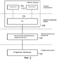
На фиг.2 схематически изображено обеспечение контроллера переключения (в этом описании также называемого контроллером переноса рабочей нагрузки) в соответствии с одним вариантом осуществления для логического отделения рабочей нагрузки, выполняемой устройством обработки данных, от конкретной аппаратной платформы внутри устройства обработки данных, используемого для выполнения этой рабочей нагрузки. 2 schematically illustrates the provision of a switch controller (also referred to as a workload transfer controller in this description) in accordance with one embodiment for logically separating the workload performed by the data processing device from a particular hardware platform within the data processing device used to perform this workload.
Фиг.3 - схема, на которой схематически изображены шаги, выполняемые как исходным процессором, так и целевым процессором в ответ на управляющее воздействие для переключения для переноса рабочей нагрузки с исходного процессора на целевой процессор, в соответствии с одним вариантом осуществления.Figure 3 is a diagram that schematically shows the steps performed by both the source processor and the target processor in response to a control action for switching to transfer workload from the source processor to the target processor, in accordance with one embodiment.
На фиг.4A схематически изображено сохранение текущего состояния архитектуры исходной компоновки схем обработки в ассоциированном с ней кэше в течение операции сохранения по фиг.3.On figa schematically depicts the preservation of the current state of the architecture of the original layout of the processing circuits in its associated cache during the save operation of figure 3.
На фиг.4B схематически изображено использование блока управления просмотром для управления переносом текущего состояния архитектуры исходной схемы обработки в целевую схему обработки во время операции восстановления по фиг.3.FIG. 4B schematically illustrates the use of the viewing control unit to control the transfer of the current state of the architecture of the original processing scheme to the target processing scheme during the recovery operation of FIG. 3.
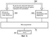
На фиг.5 изображена альтернативная структура для обеспечения ускоренного механизма для переноса текущего состояния архитектуры исходной компоновки схем обработки на целевую компоновку схем обработки во время операции переноса, в соответствии с одним вариантом осуществления.5 depicts an alternative structure for providing an accelerated mechanism for transferring the current state of the architecture of the original layout of the processing circuits to the target layout of the processing circuits during the transfer operation, in accordance with one embodiment.
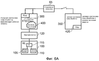
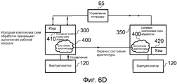
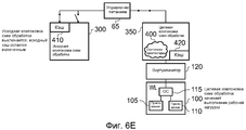
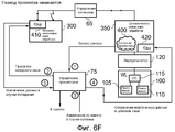
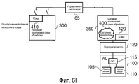
На фиг.6A-6I схематически изображены шаги выполнения переноса рабочей нагрузки с исходной схемы обработки на целевую схему обработки в соответствии с одним вариантом осуществления.6A-6I schematically illustrate steps for transferring a workload from an initial processing scheme to a target processing scheme in accordance with one embodiment.
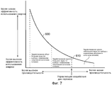
Фиг.7 - график, на котором представлено изменение эффективности использования энергии в зависимости от производительности, и на котором иллюстрируется то, как различные ядра процессора, изображенные на фиг.1, используются в различных точках вдоль этой кривой, в соответствии с одним вариантом осуществления.FIG. 7 is a graph depicting a change in energy efficiency versus performance, and which illustrates how the various processor cores of FIG. 1 are used at various points along this curve, in accordance with one embodiment.
На фиг.8A-8B схематически изображены малопроизводительный процессорный конвейер и высокопроизводительный процессорный конвейер, соответственно, используемые в одном варианте осуществления.8A-8B schematically depict a low-performance processor pipeline and a high-performance processor pipeline, respectively, used in one embodiment.
Фиг.9 - график, на котором представлено изменение в энергии, потребляемой системой обработки данных, когда выполнение рабочей нагрузки по обработке переключается между малопроизводительной схемой обработки с высокой эффективностью использования энергии и высокопроизводительной схемой обработки с малой эффективностью использования энергии.FIG. 9 is a graph showing a change in energy consumed by a data processing system when a processing workload is switched between a low-power processing circuit with high energy efficiency and a high-performance processing circuit with low energy efficiency.
Описание вариантов осуществленияDescription of Embodiments
Фиг.1 является блок-схемой, на которой схематически иллюстрируется система обработки данных в соответствии с одним вариантом осуществления. Как представлено на фиг.1, система содержит два архитектурно совместимых экземпляра схем обработки (компоновка 0 10 схем обработки и компоновка 1 50 схем обработки), но при этом эти разные экземпляры схем обработки имеют разную микроархитектуру. В частности, компоновка 10 схем обработки выполнена с возможностью функционирования с более высокой производительностью, чем компоновка 50 схем обработки, но с компромиссным решением в отношении того, что компоновка 10 схем обработки менее эффективно использует энергию, чем компоновка 50 схем обработки. Примеры микроархитектурных различий более подробно описаны ниже со ссылкой на фиг.8A-8B.1 is a block diagram schematically illustrating a data processing system in accordance with one embodiment. As shown in figure 1, the system contains two architecturally compatible instances of processing schemes (layout 0 10 processing schemes and
Каждая схема обработки может включать в себя один блок обработки (в этом описании также называемый ядром процессора), или, в качестве альтернативы, по меньшей мере, один из экземпляров схем обработки может сам содержать группу блоков обработки с идентичной микроархитектурой.Each processing scheme may include one processing unit (also referred to as a processor core in this description), or, alternatively, at least one of the processing scheme instances may itself comprise a group of processing units with identical microarchitecture.
В примере, изображенном на фиг.1, схема 10 обработки включает в себя два ядра 15, 20 процессора, которые являются идентичными как по архитектуре, так и по микроархитектуре. Напротив, схема 50 обработки содержит только одно ядро 55 процессора. В нижеследующем описании, ядра 15, 20 процессора называются "большими" ядрами, в то время как ядро 55 процессора называется "маленьким" ядром, так как ядра 15, 20 процессора обычно являются более сложными, чем ядро 55 процессора, вследствие того, что эти ядра разрабатываются с учетом (высокой) производительности, тогда как ядро 55 процессора, напротив, обычно является менее сложным вследствие разработки с учетом эффективности использования энергии.In the example shown in FIG. 1, the processing circuit 10 includes two processor cores 15, 20, which are identical in both architecture and microarchitecture. In contrast, processing circuitry 50 contains only one
На фиг.1, предполагается, что каждое из ядер 15, 20, 55 имеет свой собственный ассоциированный с ним кэш 25, 30, 60 уровня 1, соответственно, который может быть выполнен как объединенный кэш для хранения как команд, так и данных, для обращения (к нему) ассоциированного ядра или может быть выполнен с гарвардской архитектурой, обеспечивающей отдельные кэши уровня 1 команд и данных. Несмотря на то что представлено, что каждое из ядер имеет свой собственный ассоциированный с ним кэш уровня 1, это не является необходимым условием, и, в альтернативных вариантах осуществления, одно или несколько ядер могут не иметь локального кэша.Figure 1, it is assumed that each of the
В варианте осуществления, представленном на фиг.1, компоновка 10 схем обработки также включает в себя кэш 35 уровня 2, совместно используемый между ядром 15 и ядром 20, причем используется блок 40 управления просмотром для обеспечения когерентности кэша между двумя кэшами 25, 30 уровня 1 и кэшем 35 уровня 2. В одном варианте осуществления, кэш уровня 2 выполнен как инклюзивный кэш, и, следовательно, любые данные, хранящиеся в любом из кэшей 25, 30 уровня 1, также находятся в кэше 35 уровня 2. Как очевидно специалистам в данной области техники, целью блока 40 управления просмотром является обеспечение когерентности кэша между различными кэшами, так что любому ядру 15, 20 всегда может быть обеспечен доступ к самой последней версии любых данных, когда оно выдает запрос на доступ. Следовательно, только в качестве примера, если ядро 15 выдает запрос на доступ к данным, которых нет в ассоциированном кэше 25 уровня 1, то блок 40 управления просмотром перехватывает этот запрос как транслируемый далее из кэша 25 уровня 1 и устанавливает с обращением к кэшу 30 уровня 1 и/или кэшу 35 уровня 2, может ли этот запрос на доступ быть обслужен исходя из частей содержимого одного из этих других кэшей. Только если данные отсутствуют во всех упомянутых кэшах, запрос на доступ транслируется далее через межсоединение 70 в основную память 80, причем основная память 80 является памятью, которая совместно используется компоновкой 10 схем обработки и компоновкой 50 схем обработки.In the embodiment of FIG. 1, the processing circuit arrangement 10 also includes a
Блок 75 управления просмотром, обеспеченный в межсоединении 70, функционирует аналогично блоку 40 управления просмотром, но в этом случае целью является поддержка когерентности между структурой кэша, обеспеченной в компоновке 10 схем обработки, и структурой кэша, обеспеченной в компоновке 50 схем обработки. В примерах, в которых кэш 35 уровня 2 является инклюзивным кэшем, блок управления просмотром поддерживает когерентность аппаратного кэша между кэшем 35 уровня 2 компоновки 10 схем обработки и кэшем 60 уровня 1 компоновки 50 схем обработки. Однако, если кэш 35 уровня 2 выполнен как эксклюзивный кэш уровня 2, то блок 75 управления просмотром также просматривает данные, содержащиеся в кэшах 25, 30 уровня 1, для обеспечения когерентности кэша между кэшами компоновки 10 схем обработки и кэшем 60 компоновки 50 схем обработки.The
Согласно одному варианту осуществления, только одна из компоновки 10 схем обработки и компоновки 50 схем обработки активно обрабатывает рабочую нагрузку в любой момент времени. Для целей настоящей заявки можно предполагать, что рабочая нагрузка содержит, по меньшей мере, одно приложение и, по меньшей мере, одну операционную систему для выполнения этого, по меньшей мере, одного приложения, как схематически изображено по ссылочной позиции 100 на фиг.2. В этом примере приложения 105, 110 выполняются под управлением операционной системы 115, и в совокупности приложения 105, 110 и операционная система 115 формируют рабочую нагрузку 100. Можно предполагать, что приложения расположены на уровне пользователя, в то время как операционная система расположена на привилегированном уровне, и в совокупности рабочая нагрузка, формируемая приложениями и операционной системой, выполняется на аппаратной платформе 125 (представляющей вид аппаратного уровня). В любой момент времени эта аппаратная платформа обеспечивается либо компоновкой 10 схем обработки или компоновкой 50 схем обработки.According to one embodiment, only one of the layout 10 of the processing circuits and the layout 50 of the processing circuits actively processes the workload at any given time. For the purposes of this application, it can be assumed that the workload contains at least one application and at least one operating system for executing this at least one application, as schematically depicted at
Как изображено на фиг.1, компоновка 65 схем управления питанием обеспечивается для выборочного и независимого обеспечения питанием компоновки 10 схем обработки и компоновки 50 схем обработки. До переноса рабочей нагрузки с одной схемы обработки на другую, обычно только одна из упомянутых схем обработки в полной мере снабжается энергией, т.е. схема обработки, которая в настоящее время выполняет рабочую нагрузку (исходная компоновка схем обработки), а другая схема обработки (целевая компоновка схем обработки) обычно находится в режиме экономии энергии. Когда установлено, что рабочая нагрузка должна быть перенесена с одной схемы обработки на другую, во время операции переноса существует период времени, когда обе схемы обработки находятся в состоянии с включенным питанием "включено", но в некоторый момент времени после операции переноса, исходная схема обработки, с которой перенесена рабочая нагрузка, переводится в режим экономии энергии.As shown in FIG. 1, a power
Режим экономии энергии может принимать различные формы, в зависимости от реализации, и, следовательно, например, может являться одним из режима с отключенным питанием, режима частичного/полного сохранения данных, спящего режима или режима ожидания. Для специалиста в данной области техники такие режимы являются очевидными и, соответственно, в данном описании более подробно не обсуждаются.The power saving mode can take various forms, depending on the implementation, and therefore, for example, it can be one of the power-off mode, partial / full data storage mode, sleep mode, or standby mode. For a person skilled in the art such modes are obvious and, accordingly, are not discussed in more detail in this description.
Целью описанных вариантов осуществления является выполнение переключения рабочей нагрузки между схемами обработки в зависимости от требуемого уровня энергии/производительности рабочей нагрузки. Соответственно, когда рабочая нагрузка включает в себя исполнение одной или нескольких задач, требующих большой производительности, например, исполнение приложений-игр, то эта рабочая нагрузка может исполняться на высокопроизводительной схеме 10 обработки с использованием одного или обоих больших ядер 15, 20. Однако, напротив, когда рабочая нагрузка является выполнением только задач, требующих малой производительности, например, воспроизведение MP3-файлов, то вся рабочая нагрузка может быть перенесена на схему 50 обработки для получения преимущества от эффективности использования энергии, которое может быть реализовано посредством использования схемы 50 обработки.The aim of the described embodiments is to switch workload between processing circuits depending on the required energy level / productivity of the workload. Accordingly, when the workload includes the execution of one or more tasks requiring high performance, for example, the execution of application games, this workload can be executed on a high-performance processing circuit 10 using one or both large cores 15, 20. However, on the contrary when the workload is only performing tasks requiring low productivity, for example, playing MP3 files, then the entire workload can be transferred to the processing circuit 50 to obtain pre property on energy efficiency, which can be realized through the use of processing circuit 50.
Для лучшего использования указанных возможностей переключения, необходимо обеспечить механизм, который обеспечивает возможность осуществления переключения простым и эффективным способом, так что при выполнении переноса рабочей нагрузки не потребляется такое количество энергии, которое сводит на нет преимущества, полученные от переключения, а также обеспечить то, что процесс переключения является достаточно быстрым, чтобы сам он сколько-нибудь существенно не ухудшал производительность.To make better use of these switching capabilities, it is necessary to provide a mechanism that enables switching to be carried out in a simple and efficient way, so that when transferring a workload, such an amount of energy is not consumed that negates the benefits gained from switching and also ensure that the switching process is fast enough so that it itself does not significantly impair performance.
В одном варианте осуществления, указанные преимущества получены, по меньшей мере, частично посредством выполнения компоновки 10 схем обработки так, что она является архитектурно совместимой с компоновкой 50 схем обработки. Это обеспечивает возможность перемещения рабочей нагрузки с одной компоновки схем обработки на другую при обеспечении правильного функционирования. В качестве абсолютного минимума указанная архитектурная совместимость требует совместного использования обеими схемами 10 и 50 обработки идентичной архитектуры набора команд. Однако в одном варианте осуществления указанная архитектурная совместимость также влечет за собой более высокие требования к совместимости для обеспечения того, что эти два экземпляра схем обработки воспринимаются программистом как идентичные. В одном варианте осуществления, это подразумевает использование идентичных регистров архитектуры и одного или нескольких специальных регистров, в которых хранятся данные, используемые операционной системой во время исполнения приложений. С указанным уровнем совместимости архитектуры возможно маскирование от операционной системы 115 переноса рабочей нагрузки между схемами обработки, так что операционной системе абсолютно не известно то, исполняется ли рабочая нагрузка на компоновке 10 схем обработки или на компоновке 50 схем обработки.In one embodiment, these advantages are obtained, at least in part, by arranging the processing circuit arrangement 10 such that it is architecturally compatible with the processing circuit arrangement 50. This provides the ability to move the workload from one arrangement of processing schemes to another while ensuring proper functioning. As an absolute minimum, said architectural compatibility requires that both processing circuits 10 and 50 share the same instruction set architecture. However, in one embodiment, said architectural compatibility also entails higher compatibility requirements to ensure that these two instances of the processing circuitry are perceived by the programmer as identical. In one embodiment, this implies the use of identical architecture registers and one or more special registers that store data used by the operating system during application execution. With the indicated compatibility level of the architecture, it is possible to mask the workload transfer between the processing circuits from the
В одном варианте осуществления, обслуживанием переноса с одной схемы обработки на другую управляет контроллер переключения 120, изображенный на фиг.2 (также называемый там виртуализатором, а в других местах этого описания - контроллером переноса рабочей нагрузки). Контроллер переключения может быть осуществлен комбинацией аппаратных, программно-аппаратных и/или программных компонентов, но в одном варианте осуществления включает в себя программное обеспечение, аналогичное по своему характеру программному обеспечению гипервизора, которое обеспечивается в виртуальных машинах, для обеспечения возможности исполнения приложений, написанных в пределах одного набора собственных команд, на аппаратной платформе, на которой внедрен другой набор собственных команд. Вследствие архитектурной совместимости между двумя схемами 10, 50 обработки контроллер переключения 120 может маскировать перенос от операционной системы 115 только посредством маскирования одного или нескольких элементов предопределенной конкретной для процессора информации о конфигурации от операционной системы. Например, конкретная для процессора информация о конфигурации может включать в себя части содержимого регистра ID процессора CP15 и регистра типа кэша CP15.In one embodiment, transfer service from one processing circuit to another is controlled by the
В указанном варианте осуществления, контроллеру переключения тогда только необходимо обеспечить возможность того, что текущее состояние архитектуры, фиксируемое исходной схемой обработки в момент переноса, и которое не является (состоянием) в момент, когда перенос инициируется уже как доступный из совместно используемой памяти 80, является доступным для целевой схемы обработки, чтобы обеспечить возможность этой целевой схеме успешно принять на себя выполнение рабочей нагрузки. С использованием ранее описанного примера указанное состояние архитектуры обычно содержит текущие значения, сохраненные в архитектурном регистровом файле исходной компоновки схем обработки, вместе с текущими значениями одного или нескольких специальных регистров исходной компоновки схем обработки. Вследствие архитектурной совместимости схем 10, 50 обработки, если это текущее состояние архитектуры может быть перенесено из исходной схемы обработки в целевую схему обработки, то целевая схема обработки может успешно принять на себя выполнение рабочей нагрузки из исходной схемы обработки.In this embodiment, the switch controller then only needs to ensure that the current state of the architecture, fixed by the original processing scheme at the time of transfer, and which is not (state) at the time when the transfer is already initiated as available from shared
В то время как архитектурная совместимость схем 10, 50 обработки способствует переносу всей рабочей нагрузки между этими двумя схемами обработки, в одном варианте осуществления схемы 10, 50 обработки отличаются друг от друга с точки зрения микроархитектуры, так что существуют различные характеристики производительности и, следовательно, характеристики потребления энергии, ассоциированные с этими двумя схемами обработки. Как обсуждалось ранее, в одном варианте осуществления, схема 10 обработки является высокопроизводительной схемой обработки с высоким потреблением энергии, в то время как схема 50 обработки является схемой обработки с меньшей производительностью и с меньшим потреблением энергии. Эти две схемы обработки могут отличаться друг от друга с точки зрения микроархитектуры во многих отношениях, но обычно имеют, по меньшей мере, одно из разных длин исполнительного конвейера и/или разных исполнительных ресурсов. Различия в длине конвейера обычно в результате приводят к различиям в рабочей частоте, которые, в свою очередь, оказывают влияние на производительность. Аналогично различия в исполнительных ресурсах оказывают влияние на пропускную способность и, следовательно, на производительность. Следовательно, например, компоновка 10 схем обработки может иметь более значительные исполнительные ресурсы и/или больше исполнительных ресурсов, чтобы повысить пропускную способность. Кроме того, конвейеры в ядрах 15, 20 процессора могут быть выполнены с возможностью суперскалярной обработки с переупорядочением последовательности команд, в то время как более простое ядро 55 в схеме 50 обработки с эффективным использованием энергии может быть выполнено в виде конвейера с последовательностью исполнения команд по порядку. Дальнейшее обсуждение микроархитектурных различий обеспечено ниже со ссылкой на фиг.8A и фиг.8B.While the architectural compatibility of the processing circuits 10, 50 facilitates the transfer of the entire workload between the two processing circuits, in one embodiment, the processing circuits 10, 50 differ from each other in terms of microarchitecture, so that there are different performance characteristics and therefore energy consumption characteristics associated with these two processing schemes. As previously discussed, in one embodiment, the processing circuit 10 is a high-power processing circuit with a high energy consumption, while the processing circuit 50 is a processing circuit with lower productivity and lower power consumption. These two processing schemes may differ from each other in terms of microarchitecture in many respects, but usually have at least one of different lengths of the execution pipeline and / or different execution resources. Differences in conveyor length usually result in differences in operating frequency, which, in turn, affect performance. Similarly, differences in executive resources affect throughput and, therefore, performance. Therefore, for example, the arrangement 10 of the processing circuits may have more significant execution resources and / or more execution resources in order to increase throughput. In addition, the pipelines in the processor cores 15, 20 can be superscalarly processed with reordering the sequence of instructions, while the
Генерация управляющего воздействия для переноса, чтобы вызвать инициирование контроллером переключения 120 операции передачи обслуживания для переноса рабочей нагрузки с одной схемы обработки на другую, может быть запущена по множеству причин. Например, в одном варианте осуществления, может быть задан профиль приложений, и они могут быть помечены как "большой", "маленький" или "большой/маленький", в результате чего операционная система может служить интерфейсом с контроллером переключения для перемещения рабочей нагрузки соответственно. Следовательно, при таком подходе генерация управляющего воздействия для переноса может отображаться в конкретные комбинации исполняемых приложений для обеспечения того, что когда требуется высокая производительность, рабочая нагрузка исполняется на высокопроизводительной схеме 10 обработки, тогда как, когда такая производительность не требуется, вместо нее используется схема 50 обработки с эффективным использованием энергии. В одном варианте осуществления, могут исполняться алгоритмы для динамического определения того, когда запускать перенос рабочей нагрузки с одной схемы обработки на другую, на основе одного или нескольких входных значений. Например, могут быть установлены счетчики производительности для подсчета событий, чувствительных к производительности (например, количество исполнимых команд или количество операций загрузки/сохранения). По сравнению со счетчиком циклов или системным таймером, это обеспечивает возможность идентификации того, что исполняется приложение, требующее очень большой вычислительной мощности, которое может лучше обслуживаться при переключении на компоновку схем обработки с большей производительностью, или идентификации большого количества операций загрузки/сохранения, указывающие на приложение, требующее производительности IO (ввода/вывода), которые могут лучше обслуживаться на компоновке схем обработки с эффективным использованием энергии, и т.д.The generation of a transfer control action to cause the
В качестве еще одного примера того, когда может генерироваться управляющее воздействие для переноса, система обработки данных может включать в себя один или несколько термочувствительных датчиков 90 для текущего контроля температуры этой системы обработки данных во время функционирования. Это может быть в случае, когда современные высокопроизводительные схемы обработки, например, функционирующие с частотами, измеряемыми в гигагерцах (ГГц), иногда приближаются к пределам по нагреву, для функционирования в которых они предназначены, или превышают их. С использованием указанных термочувствительных датчиков 90 можно обнаруживать приближение к указанным пределам по нагреву, и в этих условиях может генерироваться управляющее воздействие для переноса для запуска переноса рабочей нагрузки на схему обработки с более эффективным использованием энергии, чтобы вызвать полное охлаждение системы обработки данных. Следовательно, при рассмотрении примера по фиг.1, в котором схема 10 обработки является высокопроизводительной схемой обработки, а схема 50 обработки является схемой обработки с меньшей производительностью, потребляющей меньше энергии, перемещение рабочей нагрузки из схема 10 обработки на схему 50 обработки при приближении к пределам по нагреву устройства вызывает последующее охлаждение этого устройства, наряду с обеспечением возможности продолжения исполнения программ, хотя и с меньшей пропускной способностью.As another example of when a control action for transfer can be generated, the data processing system may include one or more temperature-sensitive sensors 90 for monitoring the temperature of this data processing system during operation. This may be the case when modern high-performance processing schemes, for example, operating with frequencies measured in gigahertz (GHz), sometimes approach or exceed the heating limits for which they are designed to function. Using these temperature-sensitive sensors 90, it is possible to detect an approach to the specified heating limits, and under these conditions a control action can be generated to transfer to start transferring the workload to a processing circuit with more efficient use of energy in order to cause complete cooling of the data processing system. Therefore, when considering the example of FIG. 1, in which the processing circuit 10 is a high-performance processing circuit, and the processing circuit 50 is a processing circuit with lower productivity, consuming less energy, moving the workload from the processing circuit 10 to the processing circuit 50 when approaching the limits by heating the device causes subsequent cooling of this device, along with the possibility of continuing the execution of programs, albeit with less bandwidth.
Несмотря на то что на фиг.1 представлены две схемы 10, 50 обработки, очевидно, что способы вышеописанных вариантов осуществления также могут быть применены к системам, содержащим более двух разных схем обработки, с обеспечением возможности охвата системой обработки данных большего диапазона уровней энергии/производительности. В указанных вариантах осуществления, все упомянутые разные схемы обработки выполнены архитектурно совместимыми друг с другом для обеспечения возможности быстрого перемещения всей рабочей нагрузки между этими схемами обработки, но они отличается друг от друга с точки зрения микроархитектуры для обеспечения возможности выбора использования этих схем обработки в зависимости от требуемых уровней энергии/производительности.Although two processing circuits 10, 50 are shown in FIG. 1, it is obvious that the methods of the above embodiments can also be applied to systems containing more than two different processing circuits, allowing the processing system to cover a wider range of energy / performance levels . In these embodiments, all of the different processing schemes mentioned are made architecturally compatible with each other to enable fast movement of the entire workload between these processing schemes, but they differ from each other in terms of microarchitecture to allow the choice of the use of these processing schemes depending on required energy / performance levels.
Фиг.3 является схемой последовательности операций, иллюстрирующей последовательность шагов, выполняемых как на исходном процессоре, так и на целевом процессоре при переносе рабочей нагрузки из исходного процессора на целевой процессор после приема управляющего воздействия. Такое управляющее воздействие для переноса может генерироваться операционной системой 115 или виртуализатором 120 через системный программно-аппаратный интерфейс, что в результате приводит к обнаружению переключательного управляющего воздействия на шаге 200 исходным процессором (который выполняет не только рабочую нагрузку, но также и программное обеспечение виртуализатора, формирующее, по меньшей мере, часть контроллера переключения 120). Прием управляющего воздействия для переноса (в этом описании также называемого переключательным управляющим воздействием) на шаге 200 вызывает инициирование контроллером 65 управления питанием операции 205 включения питания и сброса на целевом процессоре. После указанного включения питания и сброса, на шаге 210 целевой процессор объявляет недействительным свой локальный кэш и далее на шаге 215 обеспечивает возможность просмотра. В этот момент, целевой процессор подает сигнал в исходный процессор о том, что он готов для переноса рабочей нагрузки, при этом этот сигнал вызывает исполнение исходным процессором операции сохранения состояния на шаге 225. Эта операция сохранения состояния более подробно обсуждается ниже со ссылкой на фиг.4A, но в одном варианте осуществления подразумевает, что исходная компоновка схем обработки сохраняет в своем локальном кэше свое любое текущее состояние, которое не является доступным из совместно используемой памяти во время инициирования операции передачи обслуживания, и которое является необходимым для того, чтобы целевой процессор успешно принял на себя выполнение рабочей нагрузки.FIG. 3 is a flowchart illustrating a sequence of steps performed on both the source processor and the target processor when transferring the workload from the source processor to the target processor after receiving a control action. Such a control action for transfer can be generated by the
После операции 225 сохранения состояния в целевой процессор выдается сигнал переключения состояния 230, указывающий целевому процессору на то, что он должен в данный момент начать просмотр исходного процессора для извлечения требуемого состояния архитектуры. Этот процесс происходит посредством операции 230 восстановления состояния, которая более подробно обсуждается ниже со ссылкой на фиг.4B, но которая в одном варианте осуществления подразумевает, что целевая компоновка схем обработки инициирует последовательность доступов, которые перехватываются блоком 75 управления просмотром в пределах межсоединения 70, и которая вызывает извлечение кэшированной копии состояния архитектуры в локальном кэше исходного процессора и возвращения ее в целевой процессор.After the
После шага 230, целевой процессор может принять на себя обработку рабочей нагрузки, и, соответственно, на шаге 235 начинается обычное функционирование.After
В одном варианте осуществления, после начала обычного функционирования в целевом процессоре, кэш исходного процессора может быть очищен, как указано на шаге 250, со сбросом всех измененных данных в совместно используемую память 80, и после этого питание исходного процессора может быть выключено на шаге 255. Однако, в одном варианте осуществления, для дополнительного повышения эффективности целевого процессора, исходный процессор выполнен с возможностью оставаться включенным в течение некоторого периода времени, на фиг.3 обозначенного как период просмотра. В течение этого времени, по меньшей мере, один из кэшей исходной схемы остается включенным, так что его части содержимого могут просматриваться схемой 75 управления просмотром в ответ на запрос на доступ, выдаваемый целевым процессором. После переноса всей рабочей нагрузки с использованием процесса, описанного на фиг.3, предполагается, что, по меньшей мере, в начальный период времени, после которого целевой процессор начнет оперативное управление рабочей нагрузкой, некоторые данные, требуемые во время выполнения рабочей нагрузки, остаются в кэше исходного процессора. Если исходный процессор сбросил части своего содержимого в память, и его питание выключено, то целевой процессор на этих ранних этапах будет функционировать относительно неэффективно, так как будет много промахов кэша в его локальном кэше и много выборок данных из совместно используемой памяти, что в результате существенно повлияет на производительность во время "разогрева" кэша целевого процессора, т.е. заполнения значениями данных, требуемых схеме целевого процессора для выполнения операций, задаваемых рабочей нагрузкой. Однако в результате того, что кэш исходного процессора остается включенным в течение периода просмотра, схема 75 управления просмотром может обслуживать множество этих запросов промаха кэша со ссылкой на кэш исходной схемы, что дает существенные преимущества по производительности по сравнению с извлечением этих данных из совместно используемой памяти 80.In one embodiment, after starting normal operation in the target processor, the cache of the source processor may be cleared as indicated in
Однако, как предполагается, что это преимущество по производительности длится только в течение определенного периода времени после переключения, после которого содержимое кэша исходного процессора становится устаревшим. Соответственно, в некоторый момент времени, на шаге 245, генерируется событие прекращения просмотра для блокировки просмотра, после чего, на шаге 250, очищается кэш исходного процессора, и после этого, на шаге 255, питание исходного процессора выключается. Различные сценарии, по которым может генерироваться событие прекращения просмотра, более подробно обсуждаются ниже со ссылкой на фиг.6G.However, it is assumed that this performance advantage lasts only for a certain period of time after the switchover, after which the contents of the cache of the source processor become obsolete. Accordingly, at some point in time, at
На фиг.4A схематически изображена операция сохранения, выполняемая на шаге 225 по фиг.3, в соответствии с одним вариантом осуществления. В частности, в одном варианте осуществления, состояние архитектуры, которое должно быть сохранено из исходной компоновки 300 схем обработки в локальном кэше 330, состоит из частей содержимого регистрового файла 310, к которому обращается арифметико-логическое устройство 305 (ALU, АЛУ) во время выполнения операций обработки данных, а также частей содержимого различных специальных регистров 320, идентифицирующих различные порции информации, требуемые рабочей нагрузкой для обеспечения возможности целевой схеме обработки успешно принять на себя эту рабочую нагрузку. Части содержимого специальных регистров 320 включают в себя, например, значение счетчика команд, идентифицирующего текущую исполняемую команду, а также различную другую информацию. Например, другие специальные регистры включают в себя регистры состояния процессора (например, CPSR и SPSR в архитектуре ARM), которые содержат в себе управляющие биты для режима процессора, маскирования прерываний, рабочего состояния и флагов. Другие специальные регистры включают в себя архитектурный надзор (регистр управления системой CP15 в архитектуре ARM), который содержит биты для изменения порядка следования байтов данных, включения или выключения MMU, включения или выключения кэшей данных/команд и т.д. В других специальных регистрах в CP15 хранится информация о состоянии и адресе исключения.FIG. 4A schematically illustrates a save operation performed in
Как схематически изображено на фиг.4A, исходная схема 300 обработки также обычно содержит некоторую конкретную для процессора информацию 315 о конфигурации, но эту информацию не требуется сохранять в кэше 330, так как она не относится к целевой схеме обработки. Конкретная для процессора информация 315 о конфигурации обычно является жестко закодированной в исходной схеме 300 обработки с использованием логических констант и может включать в себя, например, регистр ID процессора CP15 (который отличается для каждой схемы обработки) или части содержимого регистра типа кэша CP15 (который зависит от конфигурации кэшей 25, 30, 60, например, с указанием того, что эти кэши имеют разную длину строки). Когда операционная система 115 требует порцию конкретной для процессора информации 315 о конфигурации, то, если только процессор уже не находится в режиме гипервизора, происходит системное прерывание исполнения (и переход) в режим гипервизора. В ответ виртуализатор 120 в одном варианте осуществления может включать в себя значение требуемой информации, а в другом варианте осуществления возвращает "виртуальное" значение. В случае значения ID процессора, это виртуальное значение может выбираться идентичным как для "большого", так и для "маленького" процессоров, тем самым вызывая сокрытие фактической конфигурации аппаратного обеспечения от операционной системы 115 посредством виртуализатора 120.As shown schematically in FIG. 4A, the
Как схематически изображено на фиг.4A, во время операции сохранения, части содержимого регистрового файла 310 специальных регистров 320 сохраняются исходной компоновкой схем обработки в кэше 330 для формирования кэшированной копии. Эта кэшированная копия после этого помечается как совместно используемая, что обеспечивает возможность просмотра этого состояния целевым процессором посредством блока 75 управления просмотром.As shown schematically in FIG. 4A, during the save operation, portions of the contents of the
Операция восстановления, впоследствии выполняемая на целевом процессоре, схематически изображена на фиг.4B. В частности, целевая компоновка 350 схем обработки, в которой может существовать или отсутствовать свой собственный локальный кэш, выдает запрос на конкретный элемент состояния архитектуры, причем этот запрос перехватывается блоком 75 управления просмотром. Блок управления просмотром после этого выдает запрос на просмотр в локальный кэш 330 исходной схемы обработки для определения того, существует ли этот элемент состояния архитектуры в кэше этого источника. Вследствие шагов, выполняемых во время операции сохранения, изображенной на фиг.4A, будет обнаружено "попадание" в кэше 330 источника, что в результате приводит к возвращению этого кэшированного состояния архитектуры посредством блока 75 управления просмотром в целевую схему 350 обработки. Этот процесс может повторяться итеративно до тех пор, пока все элементы состояния архитектуры не будут извлечены посредством просмотра кэша исходной схемы обработки. Как ранее обсуждалось, любая конкретная для процессора информация о конфигурации, относящаяся к целевой схеме 350 обработки, обычно является жестко закодированной в этой целевой схеме 350 обработки. Соответственно, после завершения операции восстановления, в целевой компоновке схем обработки существует вся информация, требуемая для обеспечения ей возможности успешно принять на себя обслуживание рабочей нагрузки.The recovery operation subsequently performed on the target processor is shown schematically in FIG. 4B. In particular, the target
Кроме того, в одном варианте осуществления, вне зависимости от того, выполняется ли рабочая нагрузка 100 "большой" схемой 10 обработки, "маленькой" схемой 50 обработки, виртуализатор 120 предоставляет операционной системе 115 информацию о виртуальной конфигурации, содержащую идентичные значения, и поэтому различия в аппаратном обеспечении между "большой" и "маленькой" схемами 10, 50 обработки маскируются от операционной системы 115 виртуализатором 120. Это означает, что операционной системе 115 не известно о переносе выполнения рабочей нагрузки 100 на другую аппаратную платформу.In addition, in one embodiment, regardless of whether the
Согласно операциям сохранения и восстановления, описанным со ссылкой на фиг.4A и фиг.4B, различные экземпляры 10, 50 процессоров выполнены с когерентностью аппаратных кэшей друг другу для сокращения количества времени, энергии и сложности аппаратного обеспечения, связанных с переносом состояния архитектуры с исходного процессора на целевой процессор. В упомянутом способе используется локальный кэш исходного процессора для сохранения всего состояния, которое должно быть перенесено с исходного процессора на целевой процессор, и которое не является доступным из совместно используемой памяти во время выполнения операции переноса. Так как упомянутое состояние помечается как совместно используемое в пределах кэша исходного процессора, это обеспечивает возможность целевому процессору с когерентным аппаратным кэшем просматривать это состояние в течение операции переноса. С использованием такого способа можно переносить упомянутое состояние между экземплярами процессоров без необходимости сохранения этого состояния в основной памяти или в запоминающем элементе, отображенном в локальную память. Это, следовательно, дает существенные преимущества по производительности и потреблению энергии с увеличением множества ситуаций, в которых целесообразно переключать рабочую нагрузку с целью реализации преимуществ по потреблению энергии.According to the save and restore operations described with reference to FIGS. 4A and 4B, various processor instances 10, 50 are configured with hardware cache coherence to each other to reduce the amount of time, energy and hardware complexity associated with transferring the state of the architecture from the source processor to the target processor. The aforementioned method uses the local cache of the source processor to save all the state that must be transferred from the source processor to the target processor, and which is not accessible from shared memory during the transfer operation. Since the mentioned state is marked as shared within the cache of the source processor, this allows the target processor with a coherent hardware cache to view this state during the transfer operation. Using this method, it is possible to transfer the mentioned state between processor instances without the need to save this state in the main memory or in a storage element mapped to the local memory. This, therefore, provides significant advantages in terms of productivity and energy consumption with an increase in many situations in which it is advisable to switch the workload in order to realize the advantages in energy consumption.
Однако, несмотря на то что вышеописанный способ использования когерентности кэша обеспечивает один ускоренный механизм предоставления текущего состояния архитектуры целевому процессору без передачи текущего состояния архитектуры через совместно используемую память, он не является единственным способом, которым такой ускоренный механизм может быть реализован. Например, на фиг.5 изображен альтернативный механизм, в котором обеспечивается выделенная шина 380 между исходной компоновкой 300 схем обработки и целевой компоновкой 350 схем обработки для обеспечения возможности переноса состояния архитектуры во время операции передачи обслуживания. Следовательно, в таких вариантах осуществления, операции 225, 230 сохранения и восстановления по фиг.3 заменяются альтернативным механизмом переноса с использованием выделенной шины 380. Несмотря на то что при таком подходе обычно существуют большие затраты на аппаратное обеспечение, чем при подходе когерентности кэша (причем подход когерентности кэша обычно использует аппаратное обеспечение, уже установленное в системе обработки данных), он обеспечивает еще более быстрый способ выполнения переноса, от которого можно получить преимущества в определенных реализациях.However, despite the fact that the above method of using cache coherence provides one accelerated mechanism for providing the current state of the architecture to the target processor without transmitting the current state of the architecture through shared memory, it is not the only way such an accelerated mechanism can be implemented. For example, FIG. 5 depicts an alternative mechanism in which a
На фиг.6A-6I изображена последовательность шагов, которые выполняются для выполнения переноса рабочей нагрузки из исходной компоновки 300 схем обработки в целевую компоновку 350 схем обработки. Исходная компоновка 300 схем обработки является той из схем 10, 50 обработки, которая выполняет рабочую нагрузку до переноса, при этом целевая компоновка схем обработки является другой из схем 10, 50 обработки.FIGS. 6A-6I illustrate a series of steps that are performed to transfer a workload from source
На фиг.6A представлена система в начальном состоянии, в котором исходная компоновка 300 схем обработки снабжается энергией контроллером 65 управления питанием и выполняет рабочую нагрузку 100 по обработке, в то время как целевая компоновка 350 схем обработки находится в режиме экономии энергии. В этом варианте осуществления, режим экономии энергии является режимом с отключением питания, но, как упомянуто выше, также могут быть использованы другие типы режима экономии энергии. Рабочая нагрузка 100, включающая в себя приложения 105, 110 и операционную систему 115 для выполнения приложений 105, 110, абстрагируется от аппаратной платформы исходной компоновки 300 схем обработки посредством виртуализатора 120. Во время выполнения рабочей нагрузки 100, исходная компоновка 300 схем обработки поддерживает состояние 400 архитектуры, которое может содержать, например, части содержимого регистрового файла 310 и специальных регистров 320, как изображено на фиг.4A.FIG. 6A illustrates a system in an initial state in which the initial
На фиг.6B виртуализатор 120 обнаруживает управляющее воздействие 430 для переноса. Несмотря на то что на фиг.6B управляющее воздействие 430 для переноса представлено как внешнее событие (например, обнаружение ухода нагрева термочувствительным датчиком 90), управляющее воздействие 430 также может являться событием, запускаемым самим виртуализатором 120 или операционной системой 115 (например, операционная система 115 может быть сконфигурирована для сообщения виртуализатору 120 о том, когда должен обрабатываться конкретный тип приложения). В ответ на управляющее воздействие 430 виртуализатор 120 осуществляет управление контроллером 65 управления питанием для подачи питания в целевую компоновку 350 схем обработки для перевода ее в состояние с включенным питанием. 6B,
На фиг.6C целевая компоновка 350 схем обработки начинает исполнение виртуализатора 120. Виртуализатор 120 осуществляет управление целевой компоновкой 350 схем обработки для объявления своего кэша 420 недействительным для предотвращения ошибок при обработке, вызываемых ошибочными значениями данных, которые могут существовать в кэше 420 при включении целевой компоновки 350 схем обработки, в то время как целевой кэш 420 объявляется недействительным, исходная компоновка 350 схем обработки продолжает выполнять рабочую нагрузку 100. Когда объявление целевого кэша 420 недействительным завершается, виртуализатор 120 осуществляет управление целевой компоновкой 350 схем обработки для подачи сигнала в исходную компоновку 300 схем обработки о том, что оно готово для передачи обслуживания рабочей нагрузки 100. С продолжением обработки рабочей нагрузки 100 на исходной компоновке 300 схем обработки до тех пор, пока целевая компоновка 350 схем обработки не будет готова к операции передачи обслуживания, влияние на производительность передачи обслуживания может быть сокращено.6C, the
На следующем этапе, представленном на фиг.6D, исходная компоновка 300 схем обработки прекращает выполнение рабочей нагрузки 100. В течение этого этапа, ни исходная компоновка 300 схем обработки, ни целевая компоновка 350 схем обработки не выполняет рабочую нагрузку 100. Из исходной компоновки 300 схем обработки в целевую компоновку 350 схем обработки переносится копия состояния 400 архитектуры. Например, состояние 400 архитектуры может быть сохранено в исходном кэше 410 и восстановлено в целевой компоновке 350 схем обработки, как представлено на фиг.4A и фиг.4B, или может быть перенесено по выделенной шине, как представлено на фиг.5. Состояние 400 архитектуры содержит всю информацию, требуемую для выполнения рабочей нагрузки 100 целевой компоновкой 350 схем обработки, за исключением информации, которая уже существует в совместно используемой памяти 80.In the next step of FIG. 6D, the initial
После переноса состояния 400 архитектуры в целевую компоновку 350 схем обработки, исходная компоновка 300 схем обработки переводится в состояние экономии энергии компоновкой 65 схем управления питанием (см. Фиг.6E) за исключением того, что исходный кэш 410 продолжает снабжаться энергией. При этом целевая компоновка 350 схем обработки начинает выполнение рабочей нагрузки 100 с использованием перенесенного состояния 400 архитектуры.After the
Когда целевая компоновка 350 схем обработки начинает обработку рабочей нагрузки 100, начинается период просмотра (см. фиг.6F). В течение периода просмотра, блок 75 управления просмотром может просматривать данные, сохраняемые в исходном кэше 410, и извлекать эти данные для целевой компоновки 350 схем обработки. Когда целевая компоновка 350 схем обработки запрашивает данные, которые отсутствуют в целевом кэше 420, эта целевая компоновка 350 схем обработки запрашивает данные у блока 75 управления просмотром. После этого блок 75 управления просмотром просматривает исходный кэш 410, и если результатом этого просмотра является кэш-попадание, то блок 75 управления просмотром извлекает эти данные, полученные в результате просмотра, из исходного кэша 410 и возвращает их в целевую компоновку 350 схем обработки, в которой эти данные, полученные в результате просмотра, могут быть сохранены в целевом кэше 420. Напротив, если результатом этого просмотра является промах кэша в исходном кэше 410, то запрашиваемые данные выбираются из совместно используемой памяти 80 и возвращаются в целевую компоновку 350 схем обработки. Так как доступы к данным в исходном кэше 410 осуществляются быстрее и требуют меньше энергии, чем доступы к совместно используемой памяти 80, то просмотр исходного кэша 410 за некоторый период повышает производительность обработки и сокращает потребление энергии в течение начального периода после передачи обслуживания рабочей нагрузки 100 в целевую компоновку 350 схем обработки.When the
На шаге, представленном на фиг.6G, блок 75 управления просмотром обнаруживает событие прекращения просмотра, которое указывает на то, что поддержание исходного кэша 410 в состоянии с включенным питанием больше не является целесообразным. Событие прекращения просмотра вызывает окончание периода просмотра. Событие прекращения просмотра может быть любым из набора событий прекращения просмотра, контролируемых компоновкой 75 схем управления просмотром. Например, набор событий прекращения просмотра может включать в себя любое одно или большее количество из следующих событий:In the step of FIG. 6G, the
a) когда доля в процентах или доля попаданий при просмотре, которые в результате приводят к кэш-попаданиям в исходном кэше 410 (т.е. количество, пропорциональное "количество попаданий при просмотре"/"общее количество просмотров") падает ниже предопределенного порогового уровня после начала выполнения рабочей нагрузки 100 целевой компоновкой 350 схем обработки,a) when the percentage in percentage or the percentage of hits on viewing that result in cache hits in the original cache 410 (i.e., the amount proportional to the "number of hits on viewing" / "total views") falls below a predetermined threshold level after the start of the
b) когда количество транзакций или количество транзакций предопределенного типа (например, кэшируемых транзакций), выполненных с момента, когда целевая компоновка 350 схем обработки начала выполнение рабочей нагрузки 100, превысит предопределенный порог,b) when the number of transactions or the number of transactions of a predetermined type (for example, cached transactions) completed since the time that the
c) когда количество циклов обработки, прошедших с момента, когда целевая компоновка 350 схем обработки начала выполнение рабочей нагрузки 100, превысит предопределенный порог,c) when the number of processing cycles that have elapsed since the
d) когда к конкретной области совместно используемой памяти 80 осуществлен доступ в первый раз с момента, когда целевая компоновка 350 схем обработки начала выполнение рабочей нагрузки 100,d) when a particular area of shared
e) когда к конкретной области совместно используемой памяти 80, к которой осуществлялся доступ в течение начального периода после того, когда целевая компоновка 350 схем обработки начала выполнение рабочей нагрузки 100, не осуществляется доступ в течение предопределенного количества циклов или предопределенного периода времени,e) when a specific area of shared
f) когда целевая компоновка 350 схем обработки записывает в предопределенную ячейку памяти в первый раз с момента начала выполнения перенесенной рабочей нагрузки 100.f) when the
Эти события прекращения просмотра могут быть определены с использованием программируемых счетчиков в когерентном межсоединении 70, которое включает в себя блок 75 управления просмотром. В набор событий прекращения просмотра также могут быть включены другие типы события прекращения просмотра.These browsing termination events can be determined using programmable counters in a
При обнаружении события прекращения просмотра, блок 75 управления просмотром отправляет сигнал 440 прекращения просмотра в исходный процессор 300. Блок 75 управления просмотром прекращает просмотр исходного кэша 410 и с этого момента и далее в ответ на запросы на доступ к данным из целевой компоновки 350 схем обработки осуществляет выборку запрашиваемых данных из совместно используемой памяти 80 и возвращает выбранные данные в целевую компоновку 350 схем обработки, в которой выбранные данные могут быть помещены в кэш.Upon detection of a stop viewing event, the
На фиг.6H схема управления исходного кэша в ответ на сигнал 440 прекращения просмотра очищает кэш 410 для сохранения в совместно используемой памяти 80 всех действительных и измененных значений данных (то есть кэшируемое значение которых является более новым, чем соответствующее значение в совместно используемой памяти 80).In FIG. 6H, the source cache control circuitry in response to the
На фиг.6I питание исходного кэша 410 после этого выключается контроллером 65 управления питанием для полного перевода исходной компоновки 300 схем обработки в состояние экономии энергии. Целевая компоновка 350 схем обработки продолжает выполнять рабочую нагрузку 100. С точки зрения операционной системы 115, текущая ситуация является идентичной ситуации по фиг.6A. Операционной системе 115 не известно, что исполнение рабочей нагрузки перенесено из одной схемы обработки на другую схему обработки. Когда осуществляется еще одно управляющее воздействие для переноса, можно использовать идентичные шаги по фиг.6A-6I для переключения выполнения рабочей нагрузки обратно в первый процессор (в этом случае та из схем 10, 50 обработки, которая была "исходной компоновкой схем обработки", станет "целевой компоновкой схем обработки" и наоборот).In FIG. 6I, the power of the
В варианте осуществления по фиг.6A-6I, независимое управление питанием для кэша 410 и исходной компоновки 300 схем обработки является доступным, чтобы питание исходной компоновки 300 схем обработки, за исключением исходного кэша 410, могло быть выключено после того, как целевая компоновки 350 схем обработки начнет выполнение рабочей нагрузки (см. фиг.6E), в то время как только кэш 410 исходной компоновки 350 схем обработки остается в состоянии с включенным питанием (см. фиг.6F-6H). Далее на фиг.6I питание исходного кэша 410 выключается. Этот подход может быть полезным для экономии энергии особенно тогда, когда исходная компоновка 300 схем обработки является "большой" схемой 10 обработки.In the embodiment of FIGS. 6A-6I, independent power management for the
Однако также можно продолжать снабжать энергией всю компоновку 300 схем обработки в течение периода просмотра, и далее на фиг.6I переводить исходную компоновку 300 схем обработки в целом в состояние экономии энергии, после окончания периода просмотра и очистки исходного кэша 410. Это может быть полезным в случае, когда исходный кэш 410 является глубоко встроенным в ядро исходного процессора и не может снабжаться независимо от ядра исходного процессора. Этот подход также может являться более целесообразным, когда исходный процессор является "маленькой" схемой 50 обработки, потребление энергии которой является незначительным по сравнению с "большой" схемой 10 обработки, так как после того, как "большая" схема 10 обработки начнет обработку перенесенной рабочей нагрузки 100, то переключение "маленькой" схемы 50 обработки, отличной от кэша 60, в состояние экономии энергии в течение периода просмотра может незначительно влиять на общее потребление энергии системой. Это может означать, что дополнительная сложность аппаратного обеспечения при обеспечении отдельного управления питанием для "маленькой" схемы 50 обработки и кэша 60 "маленького" ядра может быть неоправданным.However, it is also possible to continue to power up the
В некоторых случаях, о том, что данные, сохраненные в исходном кэше 410, не потребуются целевой компоновке 350 схем обработки, когда она начнет выполнение рабочей нагрузки 100, может быть известно до переноса этой рабочей нагрузки. Например, исходная компоновка 300 схем обработки может только что завершить приложение, когда произойдет перенос, и, следовательно, данные, находящиеся в исходном кэше 410 во время переноса, относятся к завершенному приложению, а не к приложению, которое должно выполняться целевой компоновкой 350 схем обработки после переноса. В этом случае, контроллер отмены просмотра может запустить виртуализатор 120 и компоновку 75 схем управления просмотром для отмены просмотра исходного кэша 410 и для управления исходной схемой 300 обработки для очистки и выключения питания исходного кэша 410 без ожидания события прекращения просмотра для подачи сигнала окончания периода просмотра. В этом случае, способ по фиг.6A-6I выполняет переход от шага по фиг.6E сразу к шагу по фиг.6G без шага по фиг.6F, на котором данные просматриваются (и выбираются) из исходного кэша 410. Соответственно, если заранее известно, что данные в исходном кэше 410 не будут использоваться целевой компоновкой 350 схем обработки, то можно сэкономить энергию посредством перевода исходного кэша 410 и исходной компоновки 300 схем обработки в режим экономии энергии без ожидания события прекращения просмотра. Контроллер отмены просмотра может быть частью виртуализатора 120 или может быть реализован как программно-аппаратное обеспечение, исполняемое в компоновке 300 схем обработки. Контроллер отмены просмотра также может быть реализован как комбинация элементов, например, операционная система 115 может сообщать в виртуализатор 120 о том, когда заканчивается приложение, и виртуализатор 120 тогда может отменять просмотр исходного кэша 410, если перенос происходит тогда, когда приложение закончено.In some cases, that the data stored in the
Фиг.7 является графиком, на котором линия 600 иллюстрирует то, как изменяется потребление энергии в зависимости от производительности. Для различных участков этого графика, система обработки данных может быть выполнена с возможностью использования разных комбинаций ядер 15, 20, 55 процессора, изображенных на фиг.1, с целью получения подходящего оптимального соотношения между производительностью и потреблением энергии. Следовательно, например, когда должно исполняться множество очень высокопроизводительных задач, можно задействовать оба больших ядра 15, 20 схемы 10 обработки для достижения требуемой производительности. Дополнительно можно использовать способы изменения напряжения источника питания для обеспечения возможности некоторого изменения в производительности и потреблении энергии при использовании этих двух ядер.7 is a graph in which
Когда требования к производительности падают до уровня, на котором требуемая производительность может быть достигнута с использованием только одного из больших ядер, то задачи могут быть перемещены только на одно из больших ядер 15, 20, при этом питание другого ядра выключается, или оно переводится в некоторый другой режим экономии энергии. И опять же, можно использовать изменение напряжения источника питания для обеспечения возможности некоторого изменения между производительностью и потреблением энергии при использовании этого одного большого ядра. Следует отметить, что переход с двух больших ядер на одно большое ядро не требует генерации управляющего воздействия для переноса или использования вышеописанных способов переноса рабочей нагрузки, так как во всех случаях используется схема 10 обработки, а схема 50 обработки будет находиться в режиме экономии энергии. Однако, как указано пунктирной линией на фиг.7, когда производительность падает до уровня, на котором посредством небольшого ядра может быть достигнута требуемая производительность, то может генерироваться управляющее воздействие для переноса, чтобы запустить ранее описанный механизм для переноса всей рабочей нагрузки из схемы 10 обработки на схему 50 обработки, так что вся рабочая нагрузка после этого выполняется на небольшом ядре 55, при этом схема 10 обработки переводится в режим экономии энергии. И опять же, можно использовать изменение напряжения источника питания для обеспечения возможности некоторого изменения в производительности и потреблении энергии небольшого ядра 55.When performance requirements fall to a level at which the required performance can be achieved using only one of the large cores, tasks can be moved only to one of the large cores 15, 20, while the power of the other core is turned off, or it is transferred to some another energy saving mode. And again, you can use the change in the voltage of the power source to provide the possibility of some change between performance and energy consumption when using this one large core. It should be noted that the transition from two large cores to one large core does not require the generation of control action for transferring or using the above-described methods of transferring the workload, since in all cases the processing circuit 10 is used, and the processing circuit 50 will be in energy saving mode. However, as indicated by the dashed line in FIG. 7, when productivity drops to a level at which the desired performance can be achieved through a small core, a transfer control action can be generated to trigger the previously described mechanism to transfer the entire workload from processing circuit 10 to the processing circuit 50, so that the entire workload is then performed on the
На фиг.8A-8B соответственно изображены микроархитектурные различия между малопроизводительным процессорным конвейером 800 и высокопроизводительным процессорным конвейером 850 согласно одному варианту осуществления. Малопроизводительный процессорный конвейер 800 по фиг.8A подходит для маленького ядра 55 обработки данных по фиг.1, тогда как высокопроизводительный процессорный конвейер 850 по фиг.8B подходит для больших ядер 15, 20.On figa-8B, respectively, shows the microarchitectural differences between low-
Малопроизводительный процессорный конвейер 800 по фиг.8A содержит этап 810 выборки для выборки команд из памяти 80, этап 820 декодирования для декодирования выбранных команд, этап 830 выдачи для выдачи команд на исполнение и множество конвейеров исполнения, включающих в себя целочисленный конвейер 840 для выполнения целочисленных операций, конвейер 842 MAC для выполнения операций умножения с накоплением и конвейер 844 SIMD/FPU для выполнения операций SIMD (один поток команд-много потоков данных) или операций с плавающей запятой. В малопроизводительном процессорном конвейере 800, на этапе 830 выдается одна команда за раз, и команды выдаются в порядке, в котором они выбираются.The low-
Высокопроизводительный процессорный конвейер 850 по фиг.8B содержит этап 860 выборки для выборки команд из памяти 80, этап 870 декодирования для декодирования выбранных команд, этап 875 переименования для переименования регистров, заданных в декодированных командах, этап диспетчеризации для диспетчеризации команд для исполнения и множество конвейеров исполнения, включающих в себя два целочисленных конвейера 890, 892, конвейер 894 MAC и два конвейера 896, 898 SIMD/FPU. В высокопроизводительном процессорном конвейере 850, этап 880 диспетчеризации является параллельным этапу выдачи, на котором может выдаваться множество команд в различные конвейеры 890, 892, 894, 896, 898 одновременно. На этапе 880 диспетчеризации команды также могут выдаваться с изменением порядка следования. В отличие от малопроизводительного процессорного конвейера 800, длина конвейеров 896, 898 SIMD/FPU может изменяться, это означает то, что можно управлять обработкой операций, выполняемых посредством конвейеров 896, 898 SIMD/FPU, для пропуска определенных этапов. Преимущество такого подхода состоит в том, что, если все из множества конвейеров исполнения имеют разные ресурсы, то нет необходимости искусственно удлинять самый короткий конвейер для того, чтобы его длина стала идентичной длине самого длинного конвейера, а вместо этого требуется логика для того, чтобы справиться с беспорядочной сущностью результатов, выводимых разными конвейерами (например, заново все упорядочить, если произойдет исключительная ситуация при обработке).The high-
Этап 875 переименования обеспечен для отображения спецификаторов регистра, которые включены в команды программы, и идентификации конкретных регистров архитектуры, если смотреть с точки зрения модели устройства программного управления, в физические регистры, которые являются фактическими регистрами аппаратной платформы. Этап 875 переименования обеспечивает возможность обеспечения микропроцессором большего пула физических регистров, чем существует с точки зрения модели устройства программного управления на микропроцессор. Этот больший пул физических регистров является полезным в течение исполнения с изменением порядка следования команд, так как он обеспечивает возможность избегать конвейерных конфликтов, например конвейерных конфликтов запись-после-записи (WAW), посредством отображения одного регистра архитектуры, заданного в двух или нескольких разных командах, в два или несколько физических регистров, чтобы можно было параллельно исполнять разные команды. За более подробной информацией о способах переименования регистров читателю следует обратиться к заявке на патент США того же заявителя US 2008/114966 и патенту США 7590826.Renaming
Малопроизводительный конвейер 800 и высокопроизводительный конвейер 850 отличаются с точки зрения микроархитектуры по нескольким направлениям. Отличия с точки зрения микроархитектуры могут включать в себя:The low-
a) то, что конвейеры содержат разные этапы. Например, высокопроизводительный конвейер содержит этап 875 переименования, который отсутствует в малопроизводительном конвейере 800. a) that conveyors contain different stages. For example, the high-performance pipeline includes a renaming
b) то, что этапы конвейеров имеют разные возможности. Например, на этапе 830 выдачи малопроизводительного конвейера 800 команды могут выдаваться только по одной, тогда как на этапе 880 диспетчеризации высокопроизводительного конвейера 850 команды могут выдаваться параллельно. Параллельная выдача команд повышает пропускную способность обработки конвейера и, следовательно, повышает производительность.b) that conveyor stages have different capabilities. For example, in
c) то, что этапы конвейеров имеют разные длины. Например, этап 870 декодирования высокопроизводительного конвейера 850 может включать в себя три подэтапа, тогда как этап 820 декодирования малопроизводительного конвейера 800 может включать в себя один подэтап. Чем длиннее этап конвейера (большее количество подэтапов), тем больше количество команд, которые одновременно могут находиться "в полете" (в процессе обработки), и, соответственно, больше рабочая частота, с которой конвейер может функционировать, что в результате приводит к более высокому уровню производительности.c) that the stages of the conveyors have different lengths. For example, the
d) разное количество конвейеров исполнения (например, высокопроизводительный конвейер 850 содержит больше конвейеров исполнения, чем малопроизводительный конвейер 800). С обеспечением большего количества конвейеров исполнения, может быть обработано параллельно большее количество команд, и, соответственно, производительность увеличивается.d) a different number of execution conveyors (for example, high-
e) обеспечение исполнения команд по порядку (как в конвейере 800) или исполнения с изменением порядка следования команд (как в конвейере 850). Когда команды могут исполняться с изменением порядка следования, тогда производительность повышается, так как исполнение команд может планироваться динамически для оптимизации производительности. Например, в малопроизводительном конвейере 800 с последовательностью исполнения команд по порядку последовательность команд MAC должны быть исполнены конвейером 842 MAC поочередно до того, как одним из целочисленного конвейера 840 и конвейера 844 SIMD/с плавающей запятой может быть исполнена последующая команда. Напротив, в высокопроизводительном конвейере 850 команды MAC могут исполняться конвейером 894 MAC, в то время как (за исключением любых конвейерных конфликтов данных, которые не могут быть разрешены посредством переименования) последующая команда, использующая другой конвейер 890, 892, 896, 898 исполнения, может исполняться параллельно с командами MAC. Это означает, что исполнение с изменением порядка следования команд может повысить производительность обработки.e) ensuring the execution of commands in order (as in conveyor 800) or execution with a change in the sequence of commands (as in conveyor 850). When commands can be executed with a change in order, then productivity improves, since the execution of commands can be scheduled dynamically to optimize performance. For example, in a low-
Эти и другие примеры отличия микроархитектур в результате приводят к тому, что конвейер 850 обеспечивает более высокую производительность обработки, чем конвейер 800. С другой стороны, упомянутые отличия микроархитектур также вызывают большее потребление энергии конвейером 850, чем конвейером 800. Соответственно, обеспечение конвейеров 800, 850 с разными микроархитектурами дает возможность оптимизировать обработку рабочей нагрузки либо для высокой производительности (посредством использования "большой" схемы 10 обработки, содержащей высокопроизводительный конвейер 850) или для эффективности использования энергии (посредством использования "маленькой" схемы 50 обработки, содержащей малопроизводительный конвейер 800).These and other examples of differences in microarchitectures result in the
На фиг.9 изображен график, иллюстрирующий изменение потребления энергии системой обработки данных, когда выполнение рабочей нагрузки 100 переключается между большой схемой 10 обработки и маленькой схемой 50 обработки.9 is a graph illustrating a change in energy consumption of a data processing system when the execution of
В точке A фиг.9 рабочая нагрузка 100 выполняется на маленькой компоновке 50 схем обработки, и поэтому потребление энергии является низким. В точке B осуществляется управляющее воздействие для переноса, указывающее на то, что должна выполняться обработка, требующая большой производительности, и поэтому выполнение рабочей нагрузки передается в большую компоновку 10 схем обработки. Тогда потребление энергии возрастает и остается высоким в точке C, пока большая компоновка 10 схем обработки выполняет упомянутую рабочую нагрузку. В точке D предполагается, что функционируют оба больших ядра в комбинации для обработки упомянутой рабочей нагрузки. Если, однако, требования к производительности падают до уровня, когда рабочая нагрузка может обслуживаться только одним из больших ядер, то рабочая нагрузка переносится только на одно из больших ядер, а питание другого выключается, как указано, падением энергии до уровня, близкого к точке E. Однако в точке E осуществляется еще одно управляющее воздействие для переноса (указывающее на то, что требуется возврат к обработке, требующей малой производительности) для запуска переноса выполнения рабочей нагрузки обратно на маленькую компоновку 50 схем обработки.At point A of FIG. 9,
Когда маленькая компоновка 50 схем обработки начинает обработку рабочей нагрузки по обработке, большая часть большой компоновки схем обработки находится в состоянии экономии энергии, но кэш большой компоновки 10 схем обработки продолжает снабжаться энергией в течение периода просмотра (точка F на фиг.9) для обеспечения возможности извлечения данных, находящихся в кэше, для маленькой компоновки 50 схем обработки. Следовательно, кэш большой компоновки 10 схем обработки вызывает большее потребление энергии в точке F, чем в точке A, в которой снабжается энергией только маленькая компоновка 50 схем обработки. В конце периода просмотра питание кэша большой компоновки 10 схем обработки выключается, и в точке G потребление энергии возвращается на низкий уровень, когда только маленькая компоновка 50 схем обработки является активной.When the small processing circuit arrangement 50 starts processing the processing workload, most of the large processing circuit arrangement is in a power saving state, but the cache of the large processing circuit arrangement 10 continues to be energized during the viewing period (point F in FIG. 9) to enable retrieving cached data for a small layout of 50 processing circuits. Therefore, the cache of the large processing circuit arrangement 10 causes a greater energy consumption at point F than at point A, in which only the small processing circuit arrangement 50 is energized. At the end of the viewing period, the cache power of the large processing circuit arrangement 10 is turned off, and at point G, the power consumption returns to a low level when only the small processing circuit arrangement 50 is active.
Как упоминалось выше, на фиг.9 в течение периода просмотра в точке F энергии потребляется больше, чем в точке G, вследствие того, что в течение периода просмотра кэш большой компоновки схем обработки снабжается энергией. Несмотря на то что увеличение потребления энергии указывается только после перехода большой-маленький, период просмотра также может существовать после перехода маленький-большой, в течение которого данные, находящиеся в кэше маленькой компоновки 50 схем обработки, могут просматриваться для большой компоновки 10 схем обработки блоком 75 управления просмотром. Период просмотра для перехода маленький-большой не указан на фиг.9, так как энергия, потребляемая в результате того, что кэш маленькой компоновки 50 схем обработки находится в состоянии с включенным питанием в течение периода просмотра, является незначительной по сравнению с энергией, потребляемой большой схемой 10 обработки при выполнении рабочей нагрузки по обработке, и поэтому очень маленькое увеличение потребления энергии вследствие снабжения энергией кэша маленькой компоновки 50 схем обработки не заметно на графике по фиг.9.As mentioned above, in FIG. 9, more energy is consumed at point F during the viewing period than at point G, because during the viewing period, the cache of the large arrangement of processing circuits is energized. Although an increase in energy consumption is indicated only after a large-small transition, a viewing period may also exist after a small-large transition, during which data in the cache of the small processing circuit arrangement 50 can be viewed for the large processing arrangement 10 of the
В вышеописанных вариантах осуществления описывается система, содержащая два или несколько архитектурно совместимых экземпляра процессоров с микроархитектурами, оптимизированными по эффективности использования энергии или производительности. Состояние архитектуры, требуемое операционной системой и приложениями, может переключаться между экземплярами процессоров, в зависимости от требуемого уровня энергии/производительности, для обеспечения возможности переключения всей рабочей нагрузки между экземплярами процессоров. В одном варианте осуществления, только один из экземпляров процессоров выполняет рабочую нагрузку в любой данный момент времени, при этом другой экземпляр (процессора) находится в режиме экономии энергии или в процессе перехода в режим экономии энергии/выхода из него.In the above embodiments, a system is described comprising two or more architecturally compatible processors with microarchitectures optimized for energy efficiency or performance. The state of the architecture required by the operating system and applications can be switched between processor instances, depending on the required energy / performance level, to enable the entire workload to be switched between processor instances. In one embodiment, only one of the processor instances performs the workload at any given moment in time, while the other instance (processor) is in power saving mode or in the process of transitioning to / from the power saving mode.
В одном варианте осуществления, экземпляры процессоров могут быть выполнены в виде аппаратных кэшей, когерентных друг с другом, для сокращения количества времени, энергии и сложности аппаратного обеспечения, связанных с переключением состояния архитектуры с исходного процессора на целевой процессор. Это сокращает время выполнения операции переключения, что увеличивает возможности использования способов вариантов осуществления.In one embodiment, processor instances can be configured as hardware caches that are coherent with each other to reduce the amount of time, energy, and hardware complexity associated with switching the state of the architecture from the source processor to the target processor. This reduces the execution time of the switching operation, which increases the possibilities of using the methods of the embodiments.
Такие системы могут быть использованы во многих ситуациях, в которых эффективность использования энергии является важной для времени работы батареи и/или управления нагревом, и диапазон производительности является таким, что процессор с более эффективным использованием энергии может использоваться для меньших рабочих нагрузок по обработке, в то время как более высокопроизводительный процессор может использоваться для больших рабочих нагрузок по обработке.Such systems can be used in many situations in which energy efficiency is important for battery life and / or heat control, and the performance range is such that a processor with more efficient energy use can be used for lower processing workloads, while while a higher-performance processor can be used for large processing workloads.
Так как упомянутые два или несколько экземпляров (процессоров) являются архитектурно совместимыми, то с точки зрения приложения единственным различием между двумя процессорами является имеющаяся в распоряжении производительность. Посредством способов одного варианта осуществления все требуемое состояние архитектуры может перемещаться между процессорами без необходимости обращения к операционной системе, так что тогда то, на каком процессоре операционная система и приложения выполняются, является прозрачным для этой операционной системы и приложений, выполняющихся под ее управлением.Since the two or more instances (processors) mentioned are architecturally compatible, from the point of view of the application, the only difference between the two processors is the available performance. Through the methods of one embodiment, all the required state of the architecture can be moved between processors without the need to access the operating system, so then on which processor the operating system and applications are running, is transparent to this operating system and applications running under its control.
При использовании архитектурно совместимых экземпляров процессора, как описано в вышеупомянутых вариантах осуществления, общий объем состояние архитектуры, который должен быть перенесен, легко может поместиться в пределах кэша данных, и так как в современных системах обработки данных часто реализуется когерентность кэша, то при сохранении состояния архитектуры, которое должно быть переключено, внутри кэша данных, целевой процессор может быстро просмотреть это состояние при эффективном использовании энергии с использованием структур существующих схем.When using architecturally compatible processor instances, as described in the aforementioned embodiments, the total amount of state of the architecture to be transferred can easily fit within the data cache, and since modern data processing systems often implement cache coherency, maintaining the state of the architecture that needs to be switched inside the data cache, the target processor can quickly view this state with efficient use of energy using the structure existing schemes.
В одном варианте осуществления, используется механизм переключения для обеспечения пределов по нагреву, чтобы система обработки данных не была нарушена. В частности, при приближении к пределам по нагреву, вся рабочая нагрузка может быть переключена на процессор с более эффективным использованием энергии с обеспечением возможности охлаждения всей системы, в то время как продолжается исполнение программы, хотя и с более низкой пропускной способностью.In one embodiment, a switching mechanism is used to provide heating limits so that the data processing system is not disturbed. In particular, when approaching the limits for heating, the entire workload can be switched to a processor with more efficient use of energy with the possibility of cooling the entire system, while the execution of the program continues, albeit with a lower throughput.
Несмотря на то что в данном документе описывается конкретный вариант осуществления, очевидно, что изобретение не ограничивается им, и что может быть сделано множество его модификаций и дополнений к нему в рамках объема изобретения. Например, могут быть осуществлены различные комбинации признаков нижеследующих зависимых пунктов многозвенной формулы изобретения с признаками независимых пунктов формулы изобретения, не выходя за пределы объема настоящего изобретения. Although a specific embodiment is described herein, it is obvious that the invention is not limited to it, and that many modifications and additions to it can be made within the scope of the invention. For example, various combinations of features of the following dependent claims of the multi-link claims can be made with features of the independent claims without departing from the scope of the present invention.
Claims (20)
первую компоновку схем обработки для выполнения операций обработки данных,
вторую компоновку схем обработки для выполнения операций обработки данных,
причем первая компоновка схем обработки является архитектурно совместимой со второй компоновкой схем обработки, так что рабочая нагрузка, выполняемая устройством обработки данных, может выполняться или на первой компоновке схем обработки, или на второй компоновке схем обработки, причем упомянутая рабочая нагрузка содержит по меньшей мере одно приложение и по меньшей мере одну операционную систему для выполнения упомянутого по меньшей мере одного приложения,
причем первая компоновка схем обработки отличается от второй компоновки схем обработки с точки зрения микроархитектуры, так что производительность первой компоновки схем обработки отличается от производительности второй компоновки схем обработки,
причем первая и вторая компоновки схем обработки сконфигурированы так, что рабочая нагрузка выполняется одной из первой компоновки схем обработки и второй компоновки схем обработки в любой момент времени,
контроллер переключения, реагирующий на управляющее воздействие для переноса, для выполнения операции передачи обслуживания для переноса выполнения рабочей нагрузки из исходной компоновки схем обработки на целевую компоновку схем обработки, причем исходной компоновкой схем обработки является одна из первой компоновки схем обработки и второй компоновки схем обработки, а целевой компоновкой схем обработки является другая из первой компоновки схем обработки и второй компоновки схем обработки,
причем контроллер переключения выполнен с возможностью, во время операции передачи обслуживания:
(i) обеспечивать предоставление исходной компоновкой схем обработки своего текущего состояния архитектуры целевой компоновке схем обработки, причем текущим состоянием архитектуры является то состояние, которое не доступно из совместно используемой памяти, разделяемой между первой и второй компоновкой схем обработки, в момент инициирования операции передачи обслуживания, и которое является необходимым целевой компоновке схем обработки, чтобы успешно принять на себя выполнение рабочей нагрузки от исходной компоновки схем обработки, и
(ii) маскировать заранее определенную конкретную для процессора информацию о конфигурации от упомянутой по меньшей мере одной операционной системы, так что перенос рабочей нагрузки является прозрачным для упомянутой по меньшей мере одной операционной системы.1. A data processing device comprising:
a first arrangement of processing circuits for performing data processing operations,
a second arrangement of processing circuits for performing data processing operations,
moreover, the first layout of the processing circuits is architecturally compatible with the second layout of the processing circuits, so that the workload performed by the data processing device can be performed either on the first layout of the processing circuits or on the second layout of the processing circuits, said workload comprising at least one application and at least one operating system for executing said at least one application,
moreover, the first layout of the processing circuits is different from the second layout of the processing circuits in terms of microarchitecture, so that the performance of the first layout of the processing circuits differs from the performance of the second layout of the processing circuits,
moreover, the first and second layout of the processing circuits are configured so that the workload is performed by one of the first layout of the processing circuits and the second layout of the processing circuits at any time,
a switching controller responsive to the control action for transferring to perform a handover operation for transferring the execution of the workload from the initial processing circuit arrangement to the target processing circuit arrangement, the initial processing circuit arrangement being one of the first processing circuit arrangement and the second processing circuit arrangement, and the target layout of the processing circuits is another of the first layout of the processing circuits and the second layout of the processing circuits,
moreover, the switching controller is configured to, during a handover operation:
(i) ensure that the initial layout of the processing circuits provides its current state of the architecture to the target layout of the processing circuits, and the current state of the architecture is that state that is not accessible from the shared memory shared between the first and second layout of the processing circuits at the time of initiating the transfer operation, and which is a necessary target layout of the processing circuits in order to successfully assume the execution of the workload from the original layout of the processing circuits, and
(ii) masking predetermined processor-specific configuration information from said at least one operating system, so that the transfer of workload is transparent to said at least one operating system.
компоновку схем управления питанием для независимого управления питанием, подаваемым на первую компоновку схем обработки и вторую компоновку схем обработки,
причем до осуществления управляющего воздействия для переноса целевая компоновка схем обработки находится в режиме экономии энергии, а во время операции передачи обслуживания компоновка схем управления питанием вызывает выход целевой компоновки схем обработки из режима экономии энергии до того, как целевая компоновка для обработки примет на себя выполнение рабочей нагрузки.2. The data processing device according to claim 1, further comprising:
arrangement of power management circuits for independent control of power supplied to the first arrangement of processing circuits and the second arrangement of processing circuits,
moreover, before the control action is carried out for the transfer, the target arrangement of the processing circuits is in energy saving mode, and during the handover operation, the arrangement of the power control circuits causes the target arrangement of the processing circuits to exit the energy saving mode before the target arrangement for processing assumes the working load.
по меньшей мере, упомянутая исходная компоновка схем имеет ассоциированный кэш,
устройство обработки данных также содержит компоновку схем управления просмотром, и
ускоренный механизм содержит перенос текущего состояния архитектуры в целевую компоновку схем обработки с использованием ассоциированного кэша упомянутой исходной компоновки схем и упомянутой компоновки схем управления просмотром.5. The data processing device according to claim 4, in which:
at least said initial circuit arrangement has an associated cache,
the data processing device also comprises a layout of the viewing control circuits, and
the accelerated mechanism comprises transferring the current state of the architecture to the target layout of the processing circuits using the associated cache of said original circuit layout and said viewing control circuit layout.
режима с отключенным питанием,
режима частичного/полного сохранения данных,
спящего режима, или
режима ожидания.15. The data processing device according to claim 2, in which said energy saving mode is one of:
power off mode
partial / full data storage mode,
sleep mode, or
standby time.
разных длин исполнительного конвейера, или
разных исполнительных ресурсов.16. The data processing device according to one of claims 1, 2, 3, 15, in which the first layout of the processing circuits and the second layout of the processing circuits differs from the point of view of microarchitecture by the presence of at least one of:
different lengths of the executive conveyor, or
different executive resources.
компоновку схем текущего контроля нагрева для текущего контроля теплоотдачи исходной компоновки схем обработки и для запуска упомянутого управляющего воздействия для переноса, когда упомянутая теплоотдача достигнет заранее определенного уровня.17. The data processing device according to one of claims 1, 2, 3, 15, in which the initial layout of the processing circuits has a higher performance than the target layout of the processing circuits, and the data processing device further comprises:
arrangement of current heating control circuits for current control of heat transfer of the initial arrangement of processing circuits and for triggering said control action for transfer when said heat transfer reaches a predetermined level.
первое средство обработки для выполнения операций обработки данных,
второе средство обработки для выполнения операций обработки данных,
причем первое средство обработки является архитектурно совместимым со вторым средством обработки, так что рабочая нагрузка, выполняемая устройством обработки данных, может выполняться или на первом средстве обработки, или на втором средстве обработки, причем упомянутая рабочая нагрузка содержит по меньшей мере одно приложение и по меньшей мере одну операционную систему для выполнения упомянутого по меньшей мере одного приложения,
причем первое средство обработки отличается от второго средства обработки с точки зрения микроархитектуры, так что производительность первого средства обработки отличается от производительности второго средства обработки,
причем первое и второе средство обработки сконфигурированы так, что рабочая нагрузка выполняется одним из первого средства обработки и второго средства обработки в любой момент времени,
средство управления переносом, реагирующее на управляющее воздействие для переноса, для выполнения операции передачи обслуживания для переноса выполнения рабочей нагрузки из исходного средства обработки на целевое средство обработки, причем исходным средством обработки является одно из первого средства обработки и второго средства обработки, а целевым средством обработки является другое из первого средства обработки и второго средства обработки,
причем средство управления переносом выполнено с возможностью, во время операции передачи обслуживания:
(i) обеспечивать предоставление исходным средством обработки своего текущего состояния архитектуры целевому средству обработки, причем текущим состоянием архитектуры является то состояние, которое не доступно из совместно используемого средства памяти, разделяемого между первым и вторым средством обработки, в момент инициирования операции передачи обслуживания, и которое является необходимым целевому средству обработки, чтобы успешно принять на себя выполнение рабочей нагрузки от исходного средства обработки, и
(ii) маскировать заранее определенную конкретную для процессора информацию о конфигурации от упомянутой по меньшей мере одной операционной системы, так что перенос рабочей нагрузки является прозрачным для упомянутой по меньшей мере одной операционной системы.19. A data processing device comprising:
first processing means for performing data processing operations,
second processing means for performing data processing operations,
moreover, the first processing means is architecturally compatible with the second processing means, so that the workload performed by the data processing device can be performed either on the first processing means or on the second processing means, said workload comprising at least one application and at least one operating system for executing said at least one application,
moreover, the first processing means is different from the second processing means in terms of microarchitecture, so that the performance of the first processing means is different from the performance of the second processing means,
moreover, the first and second processing means are configured so that the workload is performed by one of the first processing means and the second processing means at any time,
transfer control means responsive to the control action for transfer, for performing a handover operation for transferring the execution of the workload from the original processing means to the target processing means, the initial processing means being one of the first processing means and the second processing means, and the target processing means is another from the first processing means and the second processing means,
wherein the transfer control means is configured to, during a handover operation:
(i) ensure that the initial processing means provides its current state of the architecture to the target processing means, the current state of the architecture being that state which is not accessible from the shared memory medium shared between the first and second processing means at the time of initiating the handover operation, and which is necessary for the target processing means to successfully assume the execution of the workload from the original processing means, and
(ii) masking predetermined processor-specific configuration information from said at least one operating system, so that the transfer of workload is transparent to said at least one operating system.
выполняют, в любой момент времени, рабочую нагрузку на одной из первой компоновки схем обработки и второй компоновки схем обработки,
выполняют, в ответ на управляющее воздействие для переноса, операцию передачи обслуживания для переноса выполнения рабочей нагрузки из исходной компоновки схем обработки на целевую компоновку схем обработки, причем исходной компоновкой схем обработки является одна из первой компоновки схем обработки и второй компоновки схем обработки, а целевой компоновкой схем обработки является другая из первой компоновки схем обработки и второй компоновки схем обработки,
во время операции передачи обслуживания:
(i) обеспечивают предоставление исходной компоновкой схем обработки своего текущего состояния архитектуры целевой компоновке схем обработки, причем текущим состоянием архитектуры является то состояние, которое не доступно из совместно используемой памяти, разделяемой между первой и второй компоновкой схем обработки, в момент инициирования операции передачи обслуживания, и которое является необходимым целевой компоновке схем обработки, чтобы успешно принять на себя выполнение рабочей нагрузки от исходной компоновки схем обработки, и
(ii) маскируют заранее определенную конкретную для процессора информацию о конфигурации процессора от упомянутой по меньшей мере одной операционной системы, так что передача рабочей нагрузки является прозрачной для упомянутой по меньшей мере одной операционной системы. 20. A method of operating a data processing apparatus comprising a first arrangement of processing circuits for performing data processing operations and a second arrangement of processing circuits for performing data processing operations, the first arrangement of processing circuits being architecturally compatible with the second arrangement of processing circuits, so that the workload performed by the apparatus data processing, can be performed either on the first layout of the processing circuits, or on the second layout of the processing circuits, and the said workload with holds at least one application and at least one operating system for executing said at least one application, and wherein the first layout of the processing circuits is different from the second layout of the processing circuits in terms of microarchitecture, so that the performance of the first layout of the processing circuits differs from the performance of the second arrangement of processing schemes, the method comprising the steps of:
performing, at any time, a workload on one of the first arrangement of the processing circuits and the second arrangement of the processing circuits,
performing, in response to a control action for the transfer, a handover operation for transferring the execution of the workload from the initial layout of the processing circuits to the target layout of the processing circuits, wherein the initial layout of the processing circuits is one of the first layout of the processing circuits and the second layout of the processing circuits, and the target layout processing circuitry is another of the first arrangement of processing circuitry and a second arrangement of processing circuitry,
during a handover operation:
(i) ensure that the initial layout of the processing circuits provides their current state of the architecture to the target layout of the processing circuits, and the current state of the architecture is that state that is not available from the shared memory shared between the first and second layout of the processing circuits at the time of initiating the handover operation and which is a necessary target layout of the processing circuits in order to successfully assume the execution of the workload from the original layout of the processing circuits, and
(ii) masking predetermined processor-specific processor configuration information from said at least one operating system, so that the transfer of workload is transparent to said at least one operating system.
Applications Claiming Priority (3)
| Application Number | Priority Date | Filing Date | Title |
|---|---|---|---|
| US12/659,234 US8418187B2 (en) | 2010-03-01 | 2010-03-01 | Virtualization software migrating workload between processing circuitries while making architectural states available transparent to operating system |
| US12/659,234 | 2010-03-01 | ||
| PCT/GB2011/050317 WO2011107776A1 (en) | 2010-03-01 | 2011-02-17 | A data processing apparatus and method for switching a workload between first and second processing circuitry |
Publications (2)
| Publication Number | Publication Date |
|---|---|
| RU2012141606A RU2012141606A (en) | 2014-04-10 |
| RU2520411C2 true RU2520411C2 (en) | 2014-06-27 |
Family
ID=44202159
Family Applications (1)
| Application Number | Title | Priority Date | Filing Date |
|---|---|---|---|
| RU2012141606/08A RU2520411C2 (en) | 2010-03-01 | 2011-02-17 | Data processing apparatus and method of switching workload between first and second processing circuitry |
Country Status (10)
| Country | Link |
|---|---|
| US (1) | US8418187B2 (en) |
| JP (1) | JP5823987B2 (en) |
| KR (1) | KR101802140B1 (en) |
| CN (1) | CN102782671B (en) |
| BR (1) | BR112012021102B1 (en) |
| DE (1) | DE112011100744T5 (en) |
| GB (1) | GB2490823B (en) |
| IL (1) | IL221270A (en) |
| RU (1) | RU2520411C2 (en) |
| WO (1) | WO2011107776A1 (en) |
Families Citing this family (36)
| Publication number | Priority date | Publication date | Assignee | Title |
|---|---|---|---|---|
| US8533505B2 (en) | 2010-03-01 | 2013-09-10 | Arm Limited | Data processing apparatus and method for transferring workload between source and destination processing circuitry |
| CN107608755A (en) * | 2010-07-01 | 2018-01-19 | 纽戴纳公司 | Split process between cluster by process type to optimize the use of cluster particular configuration |
| US8782645B2 (en) * | 2011-05-11 | 2014-07-15 | Advanced Micro Devices, Inc. | Automatic load balancing for heterogeneous cores |
| US8683468B2 (en) * | 2011-05-16 | 2014-03-25 | Advanced Micro Devices, Inc. | Automatic kernel migration for heterogeneous cores |
| US20130007376A1 (en) * | 2011-07-01 | 2013-01-03 | Sailesh Kottapalli | Opportunistic snoop broadcast (osb) in directory enabled home snoopy systems |
| JP6197196B2 (en) | 2011-09-06 | 2017-09-20 | インテル・コーポレーション | Power efficient processor architecture |
| GB2536825B (en) * | 2011-09-06 | 2017-08-16 | Intel Corp | Power efficient processor architecture |
| WO2013101032A1 (en) | 2011-12-29 | 2013-07-04 | Intel Corporation | Migrating threads between asymmetric cores in a multiple core processor |
| KR101975288B1 (en) * | 2012-06-15 | 2019-05-07 | 삼성전자 주식회사 | Multi cluster processing system and method for operating thereof |
| US9195285B2 (en) * | 2012-12-27 | 2015-11-24 | Intel Corporation | Techniques for platform duty cycling |
| US10162687B2 (en) * | 2012-12-28 | 2018-12-25 | Intel Corporation | Selective migration of workloads between heterogeneous compute elements based on evaluation of migration performance benefit and available energy and thermal budgets |
| US9569223B2 (en) * | 2013-02-13 | 2017-02-14 | Red Hat Israel, Ltd. | Mixed shared/non-shared memory transport for virtual machines |
| US20140269611A1 (en) * | 2013-03-14 | 2014-09-18 | T-Mobile Usa, Inc. | Communication Handovers from Networks Using Unlicensed Spectrum to Circuit-Switched Networks |
| JP6244771B2 (en) * | 2013-09-24 | 2017-12-13 | 日本電気株式会社 | Information processing system, processing apparatus, distributed processing method, and program |
| US20150095614A1 (en) * | 2013-09-27 | 2015-04-02 | Bret L. Toll | Apparatus and method for efficient migration of architectural state between processor cores |
| KR20150050135A (en) * | 2013-10-31 | 2015-05-08 | 삼성전자주식회사 | Electronic system including a plurality of heterogeneous cores and operating method therof |
| US9665372B2 (en) * | 2014-05-12 | 2017-05-30 | International Business Machines Corporation | Parallel slice processor with dynamic instruction stream mapping |
| US20150355946A1 (en) * | 2014-06-10 | 2015-12-10 | Dan-Chyi Kang | “Systems of System” and method for Virtualization and Cloud Computing System |
| US9870226B2 (en) * | 2014-07-03 | 2018-01-16 | The Regents Of The University Of Michigan | Control of switching between executed mechanisms |
| US9720696B2 (en) | 2014-09-30 | 2017-08-01 | International Business Machines Corporation | Independent mapping of threads |
| US9582052B2 (en) | 2014-10-30 | 2017-02-28 | Qualcomm Incorporated | Thermal mitigation of multi-core processor |
| US9898071B2 (en) * | 2014-11-20 | 2018-02-20 | Apple Inc. | Processor including multiple dissimilar processor cores |
| US9958932B2 (en) | 2014-11-20 | 2018-05-01 | Apple Inc. | Processor including multiple dissimilar processor cores that implement different portions of instruction set architecture |
| US9977678B2 (en) | 2015-01-12 | 2018-05-22 | International Business Machines Corporation | Reconfigurable parallel execution and load-store slice processor |
| US10133576B2 (en) | 2015-01-13 | 2018-11-20 | International Business Machines Corporation | Parallel slice processor having a recirculating load-store queue for fast deallocation of issue queue entries |
| JP6478762B2 (en) | 2015-03-30 | 2019-03-06 | ルネサスエレクトロニクス株式会社 | Semiconductor device and control method thereof |
| WO2016195274A1 (en) * | 2015-06-01 | 2016-12-08 | Samsung Electronics Co., Ltd. | Method for scheduling entity in multi-core processor system |
| US9928115B2 (en) | 2015-09-03 | 2018-03-27 | Apple Inc. | Hardware migration between dissimilar cores |
| US10775859B2 (en) * | 2016-09-23 | 2020-09-15 | Hewlett Packard Enterprise Development Lp | Assignment of core identifier |
| JP2018101256A (en) * | 2016-12-20 | 2018-06-28 | ルネサスエレクトロニクス株式会社 | Data processing system and data processing method |
| US10579575B2 (en) * | 2017-02-24 | 2020-03-03 | Dell Products L.P. | Systems and methods of management console user interface pluggability |
| US10628223B2 (en) * | 2017-08-22 | 2020-04-21 | Amrita Vishwa Vidyapeetham | Optimized allocation of tasks in heterogeneous computing systems |
| US10491524B2 (en) | 2017-11-07 | 2019-11-26 | Advanced Micro Devices, Inc. | Load balancing scheme |
| US11188379B2 (en) | 2018-09-21 | 2021-11-30 | International Business Machines Corporation | Thermal capacity optimization for maximized single core performance |
| TWI705377B (en) * | 2019-02-01 | 2020-09-21 | 緯創資通股份有限公司 | Hardware boost method and hardware boost system |
| CN110413098B (en) * | 2019-07-31 | 2021-11-16 | 联想(北京)有限公司 | Control method and device |
Citations (2)
| Publication number | Priority date | Publication date | Assignee | Title |
|---|---|---|---|---|
| RU2182353C2 (en) * | 1996-10-08 | 2002-05-10 | Арм Лимитед | Asynchronous data processing device |
| RU2006118704A (en) * | 2004-09-29 | 2007-12-20 | Сони Корпорейшн (JP) | INFORMATION PROCESSING DEVICE, PROCESS MANAGEMENT METHOD AND COMPUTER PROGRAM |
Family Cites Families (23)
| Publication number | Priority date | Publication date | Assignee | Title |
|---|---|---|---|---|
| US288748A (en) * | 1883-11-20 | John watson | ||
| US3309A (en) * | 1843-10-18 | Weaver s loom for working any number of heddles | ||
| JPH09138716A (en) * | 1995-11-14 | 1997-05-27 | Toshiba Corp | Electronic computer |
| JP3459056B2 (en) * | 1996-11-08 | 2003-10-20 | 株式会社日立製作所 | Data transfer system |
| JP3864509B2 (en) * | 1997-08-19 | 2007-01-10 | 株式会社日立製作所 | Multiprocessor system |
| JPH11203254A (en) * | 1998-01-14 | 1999-07-30 | Nec Corp | Shared process control device and machine readable recording medium for storing program |
| US6501999B1 (en) * | 1999-12-22 | 2002-12-31 | Intel Corporation | Multi-processor mobile computer system having one processor integrated with a chipset |
| US6631474B1 (en) * | 1999-12-31 | 2003-10-07 | Intel Corporation | System to coordinate switching between first and second processors and to coordinate cache coherency between first and second processors during switching |
| JP2002215597A (en) * | 2001-01-15 | 2002-08-02 | Mitsubishi Electric Corp | Multiprocessor device |
| US7100060B2 (en) | 2002-06-26 | 2006-08-29 | Intel Corporation | Techniques for utilization of asymmetric secondary processing resources |
| US20040225840A1 (en) | 2003-05-09 | 2004-11-11 | O'connor Dennis M. | Apparatus and method to provide multithreaded computer processing |
| US20050132239A1 (en) * | 2003-12-16 | 2005-06-16 | Athas William C. | Almost-symmetric multiprocessor that supports high-performance and energy-efficient execution |
| US20060064606A1 (en) * | 2004-09-21 | 2006-03-23 | International Business Machines Corporation | A method and apparatus for controlling power consumption in an integrated circuit |
| US7437581B2 (en) * | 2004-09-28 | 2008-10-14 | Intel Corporation | Method and apparatus for varying energy per instruction according to the amount of available parallelism |
| US7275124B2 (en) * | 2005-02-24 | 2007-09-25 | International Business Machines Corporation | Method and system for controlling forwarding or terminating of a request at a bus interface based on buffer availability |
| US7461275B2 (en) * | 2005-09-30 | 2008-12-02 | Intel Corporation | Dynamic core swapping |
| US20080263324A1 (en) | 2006-08-10 | 2008-10-23 | Sehat Sutardja | Dynamic core switching |
| US7624253B2 (en) | 2006-10-25 | 2009-11-24 | Arm Limited | Determining register availability for register renaming |
| US7590826B2 (en) | 2006-11-06 | 2009-09-15 | Arm Limited | Speculative data value usage |
| US7996663B2 (en) * | 2007-12-27 | 2011-08-09 | Intel Corporation | Saving and restoring architectural state for processor cores |
| US20110213947A1 (en) * | 2008-06-11 | 2011-09-01 | John George Mathieson | System and Method for Power Optimization |
| JP4951034B2 (en) * | 2009-06-25 | 2012-06-13 | 株式会社日立製作所 | Computer system and its operation information management method |
| US9367462B2 (en) * | 2009-12-29 | 2016-06-14 | Empire Technology Development Llc | Shared memories for energy efficient multi-core processors |
-
2010
- 2010-03-01 US US12/659,234 patent/US8418187B2/en active Active
-
2011
- 2011-02-17 GB GB1214368.1A patent/GB2490823B/en active Active
- 2011-02-17 DE DE112011100744T patent/DE112011100744T5/en not_active Ceased
- 2011-02-17 KR KR1020127024538A patent/KR101802140B1/en active IP Right Grant
- 2011-02-17 CN CN201180012204.1A patent/CN102782671B/en active Active
- 2011-02-17 WO PCT/GB2011/050317 patent/WO2011107776A1/en active Application Filing
- 2011-02-17 BR BR112012021102-1A patent/BR112012021102B1/en active IP Right Grant
- 2011-02-17 RU RU2012141606/08A patent/RU2520411C2/en active
- 2011-02-17 JP JP2012555487A patent/JP5823987B2/en active Active
-
2012
- 2012-08-02 IL IL221270A patent/IL221270A/en active IP Right Grant
Patent Citations (2)
| Publication number | Priority date | Publication date | Assignee | Title |
|---|---|---|---|---|
| RU2182353C2 (en) * | 1996-10-08 | 2002-05-10 | Арм Лимитед | Asynchronous data processing device |
| RU2006118704A (en) * | 2004-09-29 | 2007-12-20 | Сони Корпорейшн (JP) | INFORMATION PROCESSING DEVICE, PROCESS MANAGEMENT METHOD AND COMPUTER PROGRAM |
Also Published As
| Publication number | Publication date |
|---|---|
| DE112011100744T5 (en) | 2013-06-27 |
| WO2011107776A1 (en) | 2011-09-09 |
| RU2012141606A (en) | 2014-04-10 |
| KR20130044211A (en) | 2013-05-02 |
| GB201214368D0 (en) | 2012-09-26 |
| US8418187B2 (en) | 2013-04-09 |
| CN102782671B (en) | 2015-04-22 |
| JP2013521557A (en) | 2013-06-10 |
| CN102782671A (en) | 2012-11-14 |
| BR112012021102A2 (en) | 2017-07-11 |
| GB2490823B (en) | 2017-04-12 |
| JP5823987B2 (en) | 2015-11-25 |
| BR112012021102B1 (en) | 2020-11-24 |
| IL221270A0 (en) | 2012-10-31 |
| KR101802140B1 (en) | 2017-12-28 |
| IL221270A (en) | 2016-07-31 |
| US20110213934A1 (en) | 2011-09-01 |
| GB2490823A (en) | 2012-11-14 |
Similar Documents
| Publication | Publication Date | Title |
|---|---|---|
| RU2520411C2 (en) | Data processing apparatus and method of switching workload between first and second processing circuitry | |
| RU2550535C2 (en) | Data processing device and method of transferring workload between source and destination processing circuitry | |
| US8751833B2 (en) | Data processing system | |
| TWI494850B (en) | Providing an asymmetric multicore processor system transparently to an operating system | |
| US20110213935A1 (en) | Data processing apparatus and method for switching a workload between first and second processing circuitry | |
| US9772674B2 (en) | Performing local power gating in a processor | |
| US9442732B2 (en) | Running state power saving via reduced instructions per clock operation | |
| WO2017105638A1 (en) | Systems, methods and devices for work placement on processor cores | |
| US8612730B2 (en) | Hardware assist thread for dynamic performance profiling | |
| Gutierrez et al. | Evaluating private vs. shared last-level caches for energy efficiency in asymmetric multi-cores | |
| JP2023505459A (en) | Method of task transition between heterogeneous processors |