RU2511626C2 - Fluid batcher - Google Patents
Fluid batcher Download PDFInfo
- Publication number
- RU2511626C2 RU2511626C2 RU2012118264/12A RU2012118264A RU2511626C2 RU 2511626 C2 RU2511626 C2 RU 2511626C2 RU 2012118264/12 A RU2012118264/12 A RU 2012118264/12A RU 2012118264 A RU2012118264 A RU 2012118264A RU 2511626 C2 RU2511626 C2 RU 2511626C2
- Authority
- RU
- Russia
- Prior art keywords
- housing
- lid
- cover
- locking element
- locking
- Prior art date
Links
Images

Classifications
-
- B—PERFORMING OPERATIONS; TRANSPORTING
- B65—CONVEYING; PACKING; STORING; HANDLING THIN OR FILAMENTARY MATERIAL
- B65D—CONTAINERS FOR STORAGE OR TRANSPORT OF ARTICLES OR MATERIALS, e.g. BAGS, BARRELS, BOTTLES, BOXES, CANS, CARTONS, CRATES, DRUMS, JARS, TANKS, HOPPERS, FORWARDING CONTAINERS; ACCESSORIES, CLOSURES, OR FITTINGS THEREFOR; PACKAGING ELEMENTS; PACKAGES
- B65D50/00—Closures with means for discouraging unauthorised opening or removal thereof, with or without indicating means, e.g. child-proof closures
- B65D50/02—Closures with means for discouraging unauthorised opening or removal thereof, with or without indicating means, e.g. child-proof closures openable or removable by the combination of plural actions
- B65D50/04—Closures with means for discouraging unauthorised opening or removal thereof, with or without indicating means, e.g. child-proof closures openable or removable by the combination of plural actions requiring the combination of simultaneous actions, e.g. depressing and turning, lifting and turning, maintaining a part and turning another one
- B65D50/045—Closures with means for discouraging unauthorised opening or removal thereof, with or without indicating means, e.g. child-proof closures openable or removable by the combination of plural actions requiring the combination of simultaneous actions, e.g. depressing and turning, lifting and turning, maintaining a part and turning another one where one action elastically deforms or deflects at least part of the closure, the container or an intermediate element, e.g. a ring
- B65D50/046—Closures with means for discouraging unauthorised opening or removal thereof, with or without indicating means, e.g. child-proof closures openable or removable by the combination of plural actions requiring the combination of simultaneous actions, e.g. depressing and turning, lifting and turning, maintaining a part and turning another one where one action elastically deforms or deflects at least part of the closure, the container or an intermediate element, e.g. a ring and such deformation causes the disengagement of locking means, e.g. the release of a pawl-like element from a tooth or abutment, to allow removal of the closure by simultaneous rotation
-
- B—PERFORMING OPERATIONS; TRANSPORTING
- B65—CONVEYING; PACKING; STORING; HANDLING THIN OR FILAMENTARY MATERIAL
- B65D—CONTAINERS FOR STORAGE OR TRANSPORT OF ARTICLES OR MATERIALS, e.g. BAGS, BARRELS, BOTTLES, BOXES, CANS, CARTONS, CRATES, DRUMS, JARS, TANKS, HOPPERS, FORWARDING CONTAINERS; ACCESSORIES, CLOSURES, OR FITTINGS THEREFOR; PACKAGING ELEMENTS; PACKAGES
- B65D47/00—Closures with filling and discharging, or with discharging, devices
- B65D47/04—Closures with discharging devices other than pumps
- B65D47/06—Closures with discharging devices other than pumps with pouring spouts or tubes; with discharge nozzles or passages
- B65D47/08—Closures with discharging devices other than pumps with pouring spouts or tubes; with discharge nozzles or passages having articulated or hinged closures
- B65D47/0804—Closures with discharging devices other than pumps with pouring spouts or tubes; with discharge nozzles or passages having articulated or hinged closures integrally formed with the base element provided with the spout or discharge passage
- B65D47/0809—Closures with discharging devices other than pumps with pouring spouts or tubes; with discharge nozzles or passages having articulated or hinged closures integrally formed with the base element provided with the spout or discharge passage and elastically biased towards both the open and the closed positions
-
- B—PERFORMING OPERATIONS; TRANSPORTING
- B65—CONVEYING; PACKING; STORING; HANDLING THIN OR FILAMENTARY MATERIAL
- B65D—CONTAINERS FOR STORAGE OR TRANSPORT OF ARTICLES OR MATERIALS, e.g. BAGS, BARRELS, BOTTLES, BOXES, CANS, CARTONS, CRATES, DRUMS, JARS, TANKS, HOPPERS, FORWARDING CONTAINERS; ACCESSORIES, CLOSURES, OR FITTINGS THEREFOR; PACKAGING ELEMENTS; PACKAGES
- B65D47/00—Closures with filling and discharging, or with discharging, devices
- B65D47/04—Closures with discharging devices other than pumps
- B65D47/06—Closures with discharging devices other than pumps with pouring spouts or tubes; with discharge nozzles or passages
- B65D47/08—Closures with discharging devices other than pumps with pouring spouts or tubes; with discharge nozzles or passages having articulated or hinged closures
- B65D47/0857—Closures with discharging devices other than pumps with pouring spouts or tubes; with discharge nozzles or passages having articulated or hinged closures made separately from the base element provided with the spout or discharge passage
- B65D47/0876—Hinges without elastic bias
- B65D47/088—Hinges without elastic bias located at an edge of the base element
- B65D47/0885—Hinges without elastic bias located at an edge of the base element one part of the hinge being integral with the hinged closure and the other part with the base element, without any other additional hinge element
-
- B—PERFORMING OPERATIONS; TRANSPORTING
- B65—CONVEYING; PACKING; STORING; HANDLING THIN OR FILAMENTARY MATERIAL
- B65D—CONTAINERS FOR STORAGE OR TRANSPORT OF ARTICLES OR MATERIALS, e.g. BAGS, BARRELS, BOTTLES, BOXES, CANS, CARTONS, CRATES, DRUMS, JARS, TANKS, HOPPERS, FORWARDING CONTAINERS; ACCESSORIES, CLOSURES, OR FITTINGS THEREFOR; PACKAGING ELEMENTS; PACKAGES
- B65D2251/00—Details relating to container closures
- B65D2251/10—Details of hinged closures
- B65D2251/1016—Means for locking the closure in closed position
- B65D2251/1058—Latching mechanisms
Landscapes
- Engineering & Computer Science (AREA)
- Mechanical Engineering (AREA)
- Closures For Containers (AREA)
- Infusion, Injection, And Reservoir Apparatuses (AREA)
- Containers And Packaging Bodies Having A Special Means To Remove Contents (AREA)
- Coating Apparatus (AREA)
Abstract
Description
Область примененияApplication area
Настоящее изобретение относится к устройству для дозирования текучего материала, в частности стоматологического материала.The present invention relates to a device for dispensing a fluid material, in particular dental material.
Уровень техникиState of the art
Стоматологические материалы, как правило, выпускаются в упаковке, облегчающей приготовление из них различных составов и/или их нанесение в нужные места. Текучие стоматологические материалы часто отпускаются, например, в бутылочках с устройством для капельной дозировки, что позволяет пользователю отмерить нужное количество капель материла.Dental materials, as a rule, are available in packages that facilitate the preparation of various compositions from them and / or their application in the right places. Fluid dental materials are often dispensed, for example, in bottles with a dropping device, which allows the user to measure the required number of drops of material.
Так, например, в патенте США 5246145 описана бутылочка в сборе с системой капельной дозировки, содержащей дозирующую крышку, которая прикрепляется к бутылочке. Дозирующая крышка имеет дозирующее горлышко и отдельную крышку для закрывания горлышка. Крышка для горлышка прикреплена к дозирующей крышке с возможностью вращения относительно нее, и за счет этого его устье может быть открыто и повторно закрыто. Кроме того, данная бутылочка с устройством капельной дозировки имеет механизм фиксации крышки на устье в закрытом положении.Thus, for example, US Pat. No. 5,246,145 describes a bottle assembly with a drip dosage system comprising a metering cap that attaches to a bottle. The dispensing cap has a dispensing neck and a separate cap for closing the neck. The cap for the neck is attached to the dispensing cap for rotation relative to it, and due to this, its mouth can be opened and re-closed. In addition, this bottle with a drip dosage device has a mechanism for fixing the cap on the mouth in the closed position.
Несмотря на то, что в стоматологической практике используется большое разнообразие различных упаковок, каждая из которых обеспечивает те или иные преимущества, тем не менее остается потребность в упаковке, которая была бы легкой в использовании, относительно недорогой и обеспечивала бы относительно большой срок хранения помещенного в ней материала. Кроме того, существует особая потребность в бутылочке с капельным дозатором, которая может быть изготовлена и/или наполнена с помощью существующего оборудования, но которая обеспечивала бы определенные преимущества для пользователя в обращении с ней и которая имела бы приемлемую цену.Despite the fact that in dental practice a wide variety of different packages are used, each of which provides one or another advantage, nevertheless, there remains a need for a package that is easy to use, relatively inexpensive, and would provide a relatively long shelf life material. In addition, there is a particular need for a dropper bottle that can be manufactured and / or filled using existing equipment, but which would provide certain advantages to the user in handling it and which would have a reasonable price.
Сущность изобретенияSUMMARY OF THE INVENTION
Настоящее изобретение относится к дозирующему устройству, которое содержит корпус с выпускным патрубком и крышкой патрубка. Крышка шарнирно соединена с корпусом посредством первого шарнирного соединения так, что он может перемещаться относительно корпуса между открытым положением, в котором и выпускной патрубок открыт, и закрытым положением, в котором крышка закрывает выпускной патрубок. Кроме того, крышка и корпус выполнены с возможностью взаимной фиксации по меньшей мере в закрытом положении. Крышка имеет фиксирующий элемент, выполненный с возможностью перемещения относительно крышки между фиксирующим положением и не фиксирующим положением. Фиксирующее положение позволяет зафиксировать крышку относительно корпуса в закрытом положении, в то время как не фиксирующее положение позволяет высвободить крышку для ее перемещения из закрытого положения в открытое положение. Фиксирующий элемент имеет исполнительный механизм, предназначенный для перемещения фиксирующего элемента между фиксирующим положением и не фиксирующим положением. Кроме того, исполнительный механизм расположен относительно первого шарнирного соединения таким образом, что сила, приложенная к исполнительному механизму относительно корпуса для перемещения фиксирующего механизма в не фиксирующее положение, переводит также крышку в открытое положение. Предпочтительно, чтобы приложение силы к исполнительному механизму вызывало крутящий момент между корпусом и крышкой в направлении, обеспечивающем перевод крышки в открытое положение относительно корпуса.The present invention relates to a metering device, which comprises a housing with an outlet nozzle and a nozzle cap. The lid is pivotally connected to the casing by means of a first hinge so that it can move relative to the casing between an open position in which both the outlet pipe is open and a closed position in which the cover closes the outlet pipe. In addition, the lid and the housing are arranged to be mutually locked in at least the closed position. The lid has a locking element configured to move relative to the lid between the locking position and the non-locking position. The locking position allows the cover to be fixed relative to the housing in the closed position, while the non-locking position allows the cover to be released to move it from the closed position to the open position. The locking element has an actuator designed to move the locking element between the locking position and the non-locking position. In addition, the actuator is located relative to the first hinge so that the force applied to the actuator relative to the housing to move the locking mechanism to a non-locking position also places the cover in the open position. Preferably, the application of force to the actuator causes torque between the housing and the lid in a direction that allows the lid to move to the open position relative to the housing.
Преимуществом изобретения является то, что оно значительно облегчает работу пользователя с устройством по сравнению с аналогичными устройствами в соответствии с существующим уровнем техники. В частности, изобретение позволяет пользователю работать с дозатором одной рукой, так что он может высвобождать фиксирующий элемент и открывать дозатор в сущности одним движением в одном направлении. Кроме того, в соответствии с настоящим изобретением для вывода крышки из фиксирующего положения относительно корпуса требуется значительно меньшее усилие. Дополнительным преимуществом изобретения является то, что оно обеспечивает относительно плотное закрывание выпускного патрубка. Благодаря этому предотвращается нежелательный выход дозируемого материала через выпускной патрубок при закрытом положении дозатора. Кроме того, изобретение обеспечивает крепление крышки к устройству, в результате чего исключается возможность случайной ее потери при открытом положении дозатора. Это позволяет обеспечить достаточно длительный срок хранения дозируемого материала, так как пользователь может достаточно легко и надежно повторно закрыть дозатор. Изобретение обеспечивает также возможность относительно дешевого производства дозирующего устройства. В частности, дозатор может быть изготовлен в виде единого элемента, или по меньшей мере состоять из минимального количества деталей, что позволяет свести к минимуму затраты на его изготовление, в частности, за счет устранения этапов сборки.An advantage of the invention is that it greatly facilitates the user’s work with the device compared to similar devices in accordance with the current level of technology. In particular, the invention allows the user to work with the dispenser with one hand, so that he can release the locking element and open the dispenser in essence with one movement in one direction. In addition, in accordance with the present invention, much less force is required to bring the lid out of the locking position relative to the housing. An additional advantage of the invention is that it provides a relatively tight closure of the exhaust pipe. This prevents the undesirable exit of the dosed material through the outlet pipe when the dispenser is closed. In addition, the invention provides fastening of the cover to the device, which eliminates the possibility of accidental loss when the dispenser is open. This allows a sufficiently long shelf life of the dosed material, since the user can easily and reliably re-close the dispenser. The invention also provides the possibility of relatively cheap manufacturing of a metering device. In particular, the dispenser can be made in the form of a single element, or at least consist of a minimum number of parts, which helps to minimize the cost of its manufacture, in particular, by eliminating the assembly steps.
В одном из воплощений фиксирующий элемент упруго переводится в фиксирующее положение. Так, например, дозатор может быть изготовлен (например, сформован из пластмассы) с фиксирующим механизмом, находящимся в не фиксирующем положении (например, с крышкой, находящейся относительно корпуса в открытом положении). В данном случае дозатор должен быть изготовлен из материала, обладающего некоторой упругостью, достаточной для перевода фиксирующего элемента в фиксирующее положение. За счет этого может быть устранен дополнительный элемент конструкции, например пружина. Фиксирующий элемент может быть, например, выполнен в виде единого целого элемента с крышкой.In one of the embodiments of the locking element is elastically translated into the locking position. So, for example, the dispenser can be made (for example, molded from plastic) with a locking mechanism located in a non-locking position (for example, with a cover located relative to the housing in the open position). In this case, the dispenser should be made of a material having some elasticity sufficient to translate the locking element into the locking position. Due to this, an additional structural element, such as a spring, can be eliminated. The locking element may, for example, be made as a single unit with a cover.
В другом воплощении фиксирующий элемент имеет первый удерживающий элемент, а корпус имеет второй удерживающий элемент. Первый и второй удерживающие элементы предпочтительно выполнены таким образом, что они могут входить в зацепление друг с другом, фиксируя крышку и корпус в закрытом положении. За счет этого при закрытом положении дозатора первый и второй удерживающие элементы могут препятствовать движению крышки в сторону открытого положения. Кроме того, дозатор может быть сконструирован таким образом, что перемещение фиксирующего элемента в не фиксирующее положение при закрытом положении дозатора вызывает выход первого и второго удерживающих элементов из зацепления друг с другом. За счет этого становится возможным перемещение крышки из закрытого положения в открытое.In another embodiment, the locking member has a first holding member, and the housing has a second holding member. The first and second holding elements are preferably designed so that they can engage with each other, fixing the cover and the housing in the closed position. Due to this, when the dispenser is in the closed position, the first and second holding elements can prevent the lid from moving toward the open position. In addition, the dispenser can be designed in such a way that moving the locking element to a non-locking position when the dispenser is in the closed position causes the first and second holding elements to disengage from each other. Due to this, it becomes possible to move the cover from the closed position to the open.
В одном из воплощений фиксирующий элемент шарнирно соединен с корпусом посредством второго шарнирного соединения. За счет этого первое шарнирное соединение может обеспечивать возможность относительного вращения крышки и корпуса, в то время как второе шарнирное соединение может обеспечивать возможность относительного вращения фиксирующего элемента и крышки. В результате, например, крышка может быть выполнена с возможностью вращения относительно корпуса в первом направлении вращения для перевода крышки из закрытого положения в открытое положение при использовании изделия. В дополнение к этому фиксирующий элемент может быть выполнен с возможностью вращения относительно крышки во втором направлении вращения для перевода фиксирующего элемента из фиксирующего положения в не фиксирующее положение. Первое и второе направления вращения предпочтительно должны совпадать. За счет этого воздействие на фиксирующий элемент для освобождения крышки и корпуса друг от друга вызывает также перемещение крышки в открытое положение относительно корпуса. Это может давать особые преимущества при использовании устройства в стоматологической практике, так как в этом случае дозатором можно управлять одной рукой. Например, при лечении пациента стоматологу необходимо в одной руке держать инструмент, такой как зеркало или зонд, поэтому для дозировки материала, наносимого в полость рта пациента, у стоматолога может быть свободна только одна рука. Предлагаемое в настоящем изобретении устройство может позволять стоматологу открывать и закрывать его, а также дозировать используемый материал, обходясь одной рукой. Поэтому такой дозатор может быть очень удобным в использовании, и в стоматологической практике может обеспечивать экономию времени при лечении пациента.In one embodiment, the locking element is pivotally connected to the housing via a second pivot joint. Due to this, the first hinge joint can provide relative rotation of the cover and the housing, while the second hinge joint can provide relative rotation of the locking element and the cover. As a result, for example, the lid may be rotatable relative to the housing in a first rotation direction to translate the lid from the closed position to the open position when using the product. In addition, the locking element may be rotatable relative to the lid in the second direction of rotation to translate the locking element from the locking position to the non-locking position. The first and second directions of rotation should preferably coincide. Due to this, the action on the locking element to release the cover and the housing from each other also causes the cover to move to the open position relative to the housing. This can give particular advantages when using the device in dental practice, since in this case the dispenser can be controlled with one hand. For example, when treating a patient, the dentist needs to hold a tool in one hand, such as a mirror or a probe, therefore, for the dosage of the material applied to the patient’s oral cavity, the dentist can have only one hand free. The device proposed in the present invention can allow the dentist to open and close it, as well as to dose the material used, with one hand. Therefore, such a dispenser can be very convenient to use, and in dental practice can save time in treating a patient.
В одном из воплощений первое и второе шарнирные соединения обеспечивают возможность вращения вокруг первой оси вращения и второй оси вращения соответственно. Первая и вторая оси вращения могут быть пространственно разнесены друг от друга и могут быть протяженными в целом параллельно друг другу.In one embodiment, the first and second articulated joints allow rotation about the first axis of rotation and the second axis of rotation, respectively. The first and second axis of rotation can be spatially spaced from each other and can be extended generally parallel to each other.
Второе шарнирное соединение между фиксирующим элементом и крышкой может образовывать первую ось вращения для фиксирующего элемента. Так, например, фиксирующий элемент может иметь свободный первый конец, содержащий исполнительный механизм, и находящийся напротив него второй конец, связанный с крышкой. Соединение между фиксирующим элементом и крышкой может образовывать упругую ось вращения, в то время как фиксирующий элемент сам по себе может быть в сущности жестким. Фиксирующий элемент может дополнительно содержать упор, выполненный таким образом, что он будет упираться в крышку при переводе фиксирующего элемента из фиксирующего положения в не фиксирующее положение. Упор может быть пространственно отделен от крышки в закрытом положении. Упор может быть расположен на фиксирующем элементе между первой осью вращения и исполнительным механизмом. За счет этого упор может образовывать вторую ось вращения для фиксирующего элемента. Так, например, фиксирующий элемент при его перемещении в не фиксирующее положение может перемещаться вокруг первой оси вращения, пока упор не упрется в крышку. Как только упор упрется в крышку, фиксирующий элемент может перемещаться вокруг второй оси вращения. При этом перемещение фиксирующего элемента может иметь первый этап хода, на котором упор пространственно отделен от крышки, и последующий второй этап хода, на котором упор упирается в крышку. Как будет более подробно описано ниже, первый этап хода может быть в основном предназначен для преодоления усилия сжатия между крышкой и корпусом (предназначенного, например, для плотного закрывания выпускного патрубка крышкой), в то время как второй этап хода может обеспечивать достаточно быстрое выведение первого и второго удерживающих элементов из зацепления друг с другом. За счет этого может обеспечиваться быстрое открытие дозатора с приложением относительно малых усилий. Это в свою очередь обеспечивает удобство в обращении с устройством.The second hinge between the locking element and the cover may form a first axis of rotation for the locking element. So, for example, the locking element may have a free first end containing an actuator, and a second end located opposite it, associated with the cover. The connection between the locking element and the cover can form an elastic axis of rotation, while the locking element itself can be essentially rigid. The locking element may further comprise a stop made in such a way that it will abut against the cover when the locking element is moved from the locking position to the non-locking position. The emphasis can be spatially separated from the cover in the closed position. The emphasis may be located on the locking element between the first axis of rotation and the actuator. Due to this, the emphasis can form a second axis of rotation for the locking element. So, for example, the locking element when moving to a non-locking position can move around the first axis of rotation until the stop abuts against the cover. As soon as the stop abuts against the cover, the locking element can move around the second axis of rotation. The movement of the locking element may have a first stage of the stroke, on which the emphasis is spatially separated from the cover, and a subsequent second stage of the stroke, in which the emphasis abuts the cover. As will be described in more detail below, the first stage of the stroke can be mainly designed to overcome the compression force between the cover and the body (designed, for example, to tightly close the outlet pipe with a cover), while the second stage of the stroke can provide a sufficiently quick removal of the first and second retaining elements out of engagement with each other. Due to this, a quick opening of the dispenser with the application of relatively small efforts can be provided. This in turn provides convenience in handling the device.
В другом воплощении первый и/или второй удерживающий элементы могут иметь форму крючков. В этом случае выведение из зацепления первого и второго удерживающих элементов может толкать крышку в сторону закрытого положения во время перемещения первого и второго удерживающих элемент относительно друг друга для выведения их из зацепления друг с другом. Такая конструкция может обеспечивать более надежную фиксацию после выведения первого и второго удерживающих элементов из зацепления друг с другом.In another embodiment, the first and / or second holding elements may be in the form of hooks. In this case, disengaging the first and second holding elements may push the lid toward the closed position while the first and second holding elements are moving relative to each other to disengage them from each other. This design can provide a more reliable fixation after removing the first and second retaining elements from meshing with each other.
В одном из воплощений дозатор имеет впускной патрубок для приема дозируемого материала из контейнера. Впускной патрубок может быть расположен напротив выпускного патрубка. Впускной патрубок может, например, обеспечивать связь выпускного патрубка с контейнером, предназначенным для хранения дозируемого материала. Дозатор может иметь продольную ось. Продольная ось может быть протяженной через впускной патрубок и выпускной патрубок (например, практически через центры впускного патрубка и выпускного патрубка). Кроме того, продольная ось может быть расположена между первой и второй осями вращения. В дополнение к этому продольная ось может быть протяженной в целом перпендикулярно первой и второй осям вращения.In one embodiment, the dispenser has an inlet for receiving material to be dispensed from the container. The inlet pipe may be located opposite the outlet pipe. The inlet may, for example, provide a connection between the outlet and the container for storing the material to be dosed. The dispenser may have a longitudinal axis. The longitudinal axis can be extended through the inlet pipe and the outlet pipe (for example, practically through the centers of the inlet pipe and the outlet pipe). In addition, the longitudinal axis may be located between the first and second axes of rotation. In addition, the longitudinal axis can be extended generally perpendicular to the first and second axes of rotation.
В одном из воплощений фиксирующий элемент является в целом протяженным параллельно упомянутой продольной оси. Исполнительный элемент фиксирующего элемента может образовывать первый конец фиксирующего элемента. В данном случае фиксирующий элемент может быть ориентирован таким образом, что исполнительный элемент является протяженным в направлении, в сущности соответствующем направлению от впускного патрубка к выпускному патрубку.In one embodiment, the locking element is generally extended parallel to said longitudinal axis. The actuating element of the locking element may form the first end of the locking element. In this case, the locking element may be oriented in such a way that the actuating element is extended in a direction substantially corresponding to the direction from the inlet pipe to the outlet pipe.
Еще в одном воплощении первое соединение с возможностью вращения может быть петлей. Петля может быть расположена в непосредственной близости к первой стороне корпуса, в то время как фиксация может быть обеспечена посредством фиксатора, расположенного на второй стороне корпуса, противоположной по отношению к первой стороне корпуса. Выпускной патрубок может быть расположен между первой и второй сторонами. Крышка в закрытом положении может быть протяженной между первой и второй сторонами и тем самым закрывать выпускной патрубок. То есть крышка может быть выполнена таким образом, что в своем закрытом положении она будет закрывать выпускной патрубок своей областью, расположенной между первой и второй сторонами.In yet another embodiment, the first rotatable connection may be a loop. The hinge can be located in close proximity to the first side of the housing, while fixing can be achieved by means of a latch located on the second side of the housing, opposite to the first side of the housing. An outlet may be located between the first and second sides. The cap in the closed position can be extended between the first and second sides and thereby close the exhaust pipe. That is, the cap can be made in such a way that in its closed position, it will cover the outlet pipe with its region located between the first and second sides.
Еще в одном воплощении петля выполнена таким образом, что она автоматически переводит корпус и крышку из промежуточного положения между открытым положением и закрытым положением в открытое положение или закрытое положение. То есть петля может быть выполнена таким образом, что он будет иметь два устойчивых положения. Петля, имеющая два устойчивых положения, автоматически переходит в открытое или закрытое положение, но не будет оставаться в промежуточных положениях. Кроме того, петля может быть живой петлей, составляющей единое целое с крышкой и корпусом. Это может способствовать уменьшению себестоимости производства изделия, так как живая петля может быть сформирована на одной производственной операции вместе с крышкой и корпусом. Кроме того, петля может быть сформована способом двухэтапного инжекционного формования вместе с крышкой и корпусом. За счет этого петля опять же может составлять единое целое с крышкой и корпусом, но при этом может быть сформирована из материала, отличного от материала крышки и корпуса.In yet another embodiment, the hinge is configured such that it automatically moves the housing and cover from an intermediate position between the open position and the closed position to the open position or closed position. That is, the loop can be made in such a way that it will have two stable positions. A loop with two stable positions automatically goes into open or closed position, but will not remain in intermediate positions. In addition, the hinge can be a living loop that is integral with the lid and housing. This can help reduce the cost of production of the product, since a living loop can be formed in one production operation together with the lid and housing. In addition, the loop can be molded by a two-stage injection molding process together with a lid and a housing. Due to this, the loop can again be integral with the cover and the body, but it can be formed from a material different from the material of the cover and the body.
В одном из воплощений крышка в закрытом положении прижата к выпускному патрубку. Усилие фиксации, прижимающее крышку к выпускному патрубку, может поддерживаться находящимися в зацеплении друг с другом удерживающими элементами в закрытом положении дозатора. Усилие фиксации может быть, например, создано пользователем при переводе им крышки в закрытое положение.In one embodiment, the cap in the closed position is pressed against the exhaust pipe. The clamping force pressing the cap against the outlet pipe can be supported by the holding elements engaged with each other in the closed position of the dispenser. The fixing force can, for example, be created by the user when the lid is moved to the closed position.
В другом воплощении крышка содержит уплотнение для плотного закрывания выпускного патрубка в закрытом положении. Плотное закрытие выпускного патрубка может препятствовать нежелательному выходу дозируемого материала через патрубок. Уплотнение может быть, например, выполнено из резины. Кроме того, уплотнение может быть выполнено из мягкого термопластического материала или термопластического эластомера. Благодаря этому настоящее изобретение может обеспечивать максимальный срок хранения материалов, содержащихся в контейнере. Кроме того, при такой конструкции дозатор в закрытом положении может храниться «вверх ногами», то есть с крышкой внизу и контейнером вверху, и при этом материал не будет вытекать из контейнера.In another embodiment, the cap comprises a seal for tightly closing the outlet pipe in the closed position. Tight closure of the discharge nozzle may prevent the undesired exit of the metered material through the nozzle. The seal may, for example, be made of rubber. In addition, the seal may be made of a soft thermoplastic material or a thermoplastic elastomer. Due to this, the present invention can provide a maximum shelf life of materials contained in the container. In addition, with this design, the dispenser in the closed position can be stored upside down, that is, with the lid at the bottom and the container at the top, and the material will not leak out of the container.
В одном из воплощений дозатор содержит контейнер для помещения в него дозируемого материала. Контейнер может, например, содержать элемент соединения, сопрягающийся с ответным элементом соединения на корпусе дозатора. Такое их взаимное соединение может, например, содержать резьбу или любую другую подходящую структуру, обеспечивающую удержание корпуса дозатора на контейнере.In one embodiment, the dispenser comprises a container for containing the metered material. The container may, for example, comprise a coupling element mating with a mating coupling element on a dispenser housing. Such their mutual connection may, for example, contain a thread or any other suitable structure that ensures that the dispenser housing is held on the container.
Еще в одном воплощении исполнительный элемент и контейнер расположены относительно друг друга таким образом, что пользователь может взять контейнер в руку, положив большой палец на исполнительный механизм, так что исполнительный элемент может быть переведен в не фиксирующее положение движением большого пальца в направлении от руки пользователя, и при этом после достижения не фиксирующего положения крышка может быть переведена в открытое положение путем дальнейшего движения большого пальца в сущности в том же направлении от руки.In yet another embodiment, the actuator and the container are arranged relative to each other so that the user can take the container in his hand by placing his thumb on the actuator, so that the actuator can be moved to a non-locking position by moving the thumb in the direction from the user's hand, and in this case, after reaching the non-locking position, the lid can be moved to the open position by further movement of the thumb in essence in the same direction by hand.
В одном из воплощений контейнер образует бутылку. Стенки контейнера, образующего бутылку, могут быть прозрачными. Прозрачные стенки контейнера могут содержать светофильтр, например светофильтр, не пропускающий голубой свет. Дело в том, что голубой свет может, например, взаимодействовать с фотоинициаторами, содержащимися в материале, помещенном в контейнер, что может привести к отверждению материала или прочим нежелательным изменениям. Поэтому задержание голубого света может препятствовать преждевременному старению материала, и тем самым обеспечивать максимальный срок его хранения в контейнере.In one embodiment, the container forms a bottle. The walls of the container forming the bottle may be transparent. The transparent walls of the container may contain a filter, for example a filter that does not transmit blue light. The fact is that blue light can, for example, interact with photoinitiators contained in a material placed in a container, which can lead to curing of the material or other undesirable changes. Therefore, the retention of blue light can prevent premature aging of the material, and thereby ensure maximum shelf life in the container.
Контейнер может дополнительно содержать дозируемый материал. Материал может быть, например, адгезивом, применяемым в стоматологической практике.The container may further comprise a metered material. The material may be, for example, an adhesive used in dental practice.
Еще в одном из воплощений дозатор может содержать капельное сопло, образующее выпускной патрубок. Капельное сопло может обеспечивать точную дозировку материала.In yet another embodiment, the dispenser may comprise a drip nozzle forming an outlet. A drip nozzle can provide an accurate dosage of the material.
Краткое описание чертежейBrief Description of the Drawings
Фиг.1. Вид сбоку устройства в соответствии с одним из воплощений изобретения, в открытом положении.Figure 1. A side view of a device in accordance with one embodiment of the invention, in the open position.
Фиг.2. Вид сбоку устройства, изображенного на фиг.1, в закрытом положении.Figure 2. Side view of the device shown in figure 1, in the closed position.
Фиг.3. Аксонометрический вид устройства в соответствии с одним из воплощений изобретения, удерживаемого пользователем.Figure 3. Axonometric view of the device in accordance with one embodiment of the invention held by the user.
Фиг.4. Аксонометрический вид устройства в соответствии с еще одним из воплощений изобретения, удерживаемого пользователем.Figure 4. Axonometric view of the device in accordance with another embodiment of the invention held by the user.
Фиг.5. Аксонометрический вид дозатора в соответствии с одним из воплощений изобретения.Figure 5. Axonometric view of the dispenser in accordance with one embodiment of the invention.
Фиг.6. Местный разрез крышки с фиксирующим элементом в соответствии с одним из воплощений изобретения.6. A local section of the lid with a locking element in accordance with one embodiment of the invention.
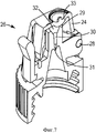
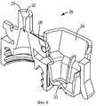
Фиг.7. Аксонометрический вид дозатора в соответствии с еще одним воплощением изобретения, в закрытом положении.7. Axonometric view of the dispenser in accordance with another embodiment of the invention, in the closed position.
Фиг.8. Аксонометрический вид дозатора, изображенного на фиг.7, в открытом положении.Fig. 8. Axonometric view of the dispenser shown in Fig.7, in the open position.
Подробное описание изобретенияDETAILED DESCRIPTION OF THE INVENTION
На фиг.1 показано устройство 1, имеющее дозатор 6 с выпускным патрубком 3 и крышкой 4, предназначенной для закрывания выпускного патрубка 3. Устройство 1 изображено в открытом положении, в котором выпускной патрубок 3 открыт. В открытом положении устройство 1 может использоваться для дозировки материала из выпускного патрубка 3 в требуемом месте.1 shows a
Дозатор 6 имеет крышку 4 и корпус 5, соединенные друг с другом с возможностью перемещения или вращения относительно друг друга. В одном из воплощений соединение крышки 4 и корпуса 5 обеспечивается посредством петли 8. Поэтому крышка 4 может быть перемещена относительно корпуса 5 в закрытое положение, в котором выпускной патрубок 3 закрыт, как показано на фиг.2. В закрытом положении выпускной патрубок плотно закрыт крышкой 4 для предотвращения нежелательного выхода дозируемого материала через выпускной патрубок.The dispenser 6 has a
Устройство 1, изображенное на фиг.1 и 2, имеет продольное измерение, протяженное в целом вдоль продольной оси А. Продольное измерение может соответствовать направлению, вдоль которого материал подается к выпускному патрубку для его дозировки. Сведущим в данной области техники будет понятно, что продольное измерение необязательно должно быть прямым, как показано на данных чертежах, но может быть также криволинейным или иметь криволинейные участки. Крышка 4 выполнена с возможностью вращения относительно корпуса 5 в сторону от продольной оси А устройства 1. Так, например, крышка 4 может быть выполнена с возможностью вращения в целом вокруг первой оси вращения, которая смещена от продольной оси А и в целом перпендикулярна продольной оси А. Такая конструкция позволяет отодвинуть крышку 4 достаточно далеко от выпускного патрубка 3, что снижает вероятность загрязнения крышки дозируемым материалом при пользовании устройством 1. С другой стороны, предотвращается утеря крышки 4, так как она остается скрепленной с корпусом 5 во время перемещения крышки 4 относительно корпуса 5.The
Кроме того, крышка 4 и корпус 5 выполнены таким образом, что они могут входить в зацепление и фиксироваться друг с другом по меньшей мере в закрытом положении. За счет этого крышка прочно удерживается, когда она находится в закрытом положении, что может быть дополнительным преимуществом при хранении и/или транспортировке устройства 1. Крышка 4 имеет фиксирующий элемент 7. Фиксирующий элемент 7 позволяет вывести крышку 4 из фиксирующего положения, так чтобы ее можно было перевести в открытое положение, например, чтобы это мог бы сделать пользователь при использовании устройства. Фиксирующий элемент в нормальном состоянии может находиться в фиксирующем положении и может быть выполнен с возможностью перемещения между фиксирующим положением и не фиксирующим положением. На фиг.2 изображено устройство 1, в котором фиксирующий элемент 7 фиксирует крышку 4 относительно корпуса 5 в закрытом положении. Фиксирующий элемент 7 из показанного положения может быть переведен в не фиксирующее положение (показанное пунктирными линями), и за счет этого обеспечивается снятие фиксации крышки относительно корпуса. В не фиксирующем положении становится возможным вращение крышки относительно корпуса из закрытого положения в открытое положение. Перемещение фиксирующего элемента 7 может быть дополнительно ограничено только перемещением между фиксирующим и не фиксирующим положением. В частности, фиксирующий элемент 7 может удерживаться от чрезмерного перемещения из фиксирующего положения в сторону не фиксирующего положения и за его пределы. Это может быть достигнуто, например, при помощи гибкой полоски, расположенной между фиксирующим элементом и крышкой. При перемещении фиксирующего элемента из фиксирующего положения в не фиксирующее положение полоска может разгибаться, но она может быть в сущности не растяжимой. За счет этого может предотвращаться неправильное обращение пользователя с устройством.In addition, the
Перевод фиксирующего элемента в не фиксирующее положение может осуществляться путем приложения силы F к фиксирующему элементу, как показано на фиг.2. Сила F предпочтительно должна быть приложена относительно корпуса 5. Так, например, корпус может удерживаться рукой пользователя при приложении силы к фиксирующему элементу 7. Подходящее направление приложения силы для перевода фиксирующего элемента из фиксирующего положения в не фиксирующее положение предопределяется расположением (например, формой и ориентацией) фиксирующего элемента, как будет более подробно описано ниже. Направление приложения силы предпочтительно предопределяется таким образом, что она будет ориентирована поперек продольной оси А. Кроме того, направление действия силы предпочтительно должно быть вдоль линии, в целом перпендикулярной первой оси вращения, например, обеспечиваемой петлей, но не должно пересекать первую ось вращения. За счет этого воздействие на фиксирующий элемент вызывает также момент силы между корпусом 5 и крышкой 4 вокруг первой оси вращения. За счет этого, когда устройство удерживают за корпус 5, сила F, приложенная к фиксирующему элементу, вызывает момент силы Т, толкающий крышку в открытое положение. При этом если сила F сохраняется вплоть до достижения не фиксирующего положения, фиксация крышки снимается, и она продолжает вращаться далее в сторону открытого положения. За счет этого выведение крышки из фиксирующего положения относительно корпуса, а также их дальнейшее относительное перемещение к открытому положению может быть сделано за один этап. Это может облегчать работу с устройством, и в частности, делает возможным его открытие одной рукой, как показано на фиг.3 и будет более подробно описано ниже.The locking element can be moved to a non-locking position by applying a force F to the locking element, as shown in FIG. The force F should preferably be applied relative to the
Устройство 1 дополнительно содержит контейнер 2. В изображенном примере контейнер 2 имеет форму бутылки. Бутылка может быть гибкой, так, чтобы пользователь мог сжать ее для дозирования материала. Контейнер 2 предпочтительно имеет отверстие, закрываемое дозатором 6. Отверстие должно быть достаточно большим, чтобы обеспечить удобное наполнение контейнера материалом в процессе производства. Дозатор 6 может обеспечивать удобную дозировку материала из контейнера при использовании устройства. Кроме того, контейнер 2 может быть использован для удержания устройства 1. А именно, пользователь может удобно держать устройство 1 за контейнер 2 для приведение в действие фиксирующего элемента и открытия крышки 4.The
На фиг.3 показано устройство 1, удерживаемое пользователем в руке. Пользователь держит устройство 1 за контейнер (не виден) так, что фиксирующий элемент 7 ориентирован в сторону большого пальца пользователя. Форма и расположение фиксирующего элемента по отношению к остальным частям устройства таковы, что приведение в действие фиксирующего элемента в целом возможно только в направлении поперек продольного измерения А устройства. Таким образом, сама конструкция устройства предопределяет направление силы F, обеспечивающей момент, переводящий крышку 4 в открытое положение.Figure 3 shows the
Как показано на фиг.4, в альтернативном воплощении фиксирующий элемент 7' устройства 1' может иметь и другую форму, которая тем не менее обеспечивает момент, достаточный для перевода крышки 4' в открытое положение. Сведущими в данной области техники могут быть предложены и другие формы и/или положения фиксирующего элемента, которые обеспечивают аналогичный и/или эквивалентный эффект, и они также входят в масштаб настоящего изобретения.As shown in FIG. 4, in an alternative embodiment, the locking element 7 'of the device 1' may also have another shape, which nonetheless provides a moment sufficient to bring the cover 4 'into the open position. Other forms and / or positions of the locking element that provide a similar and / or equivalent effect, and they are also included in the scope of the present invention, may be skilled in the art.
На фиг.5 представлен аксонометрический вид дозатора 6. Как показано на чертеже, дозатор 6 имеет корпус 5 и крышку 4, образующие единый целый элемент. В одном из воплощений корпус 5 и крышка 4 связаны друг с другом живой петлей 18. Дозатор 6 дополнительно имеет капельное сопло 9, содержащее выпускной патрубок 3. Капельное сопло 9 выступает из корпуса 5. Корпус 5 дополнительно имеет впускной патрубок 10 (не виден), предназначенный для обеспечения связи между контейнером (не показан) и выпускным патрубком. В одном из воплощений корпус 5 дозатора 6 образует крышку, принимающую верхнюю часть контейнера. Крышка корпуса может, например, содержать внутреннюю резьбу, входящую в зацепление с ответной наружной резьбой контейнера. Сведущим в данной области техники будут очевидны и другие конструкции, обеспечивающие соединение дозатора 6 с контейнером, например соединение защелкиванием, склеиванием или соединение, в котором внутренняя резьба расположена на контейнере, а внешняя резьба выполнена на дозаторе 6. Возможны также и другие типы соединений, обеспечивающие надежное удержание дозатора на контейнере.Figure 5 shows a perspective view of the dispenser 6. As shown in the drawing, the dispenser 6 has a
Капельное сопло может быть дополнительно сформировано в виде компонента, отдельного от корпуса. В таком случае капельное сопло может иметь элемент, который входит в отверстие контейнера и может выступать через отверстие в корпусе дозатора, когда изделие полностью собрано. За счет этого с корпусами, в целом имеющими аналогичную конструкцию, могут использоваться различные капельные сопла. Это может, кроме всего прочего, способствовать снижению производственных затрат, так как аналогичные дозаторы могут производится в большем количестве по сравнению с дозаторами, в которых требуются капельные сопла различной конфигурации.The drip nozzle may be further formed as a component separate from the housing. In this case, the drip nozzle may have an element that enters the opening of the container and can protrude through the hole in the dispenser housing when the product is fully assembled. Due to this, various drip nozzles can be used with housings generally having a similar design. This can, among other things, help reduce production costs, since similar dispensers can be produced in larger quantities compared to dispensers that require drip nozzles of various configurations.
На фиг.5 показан дозатор 6 с крышкой 4 в открытом положении, в котором выпускной патрубок 3 открыт. Живая петля 18 позволяет крышке 4 вращаться относительно корпуса 5. Живая петля 18 дозатора 6, как показано на данном чертеже, может иметь два устойчивых положения, так что крышка 4 и корпус 5 из промежуточных положений будут приводиться в открытое положение либо в закрытое положение. Петля 18 в данном и прочих воплощениях может обеспечивать первую ось вращения, ориентированную в сущности перпендикулярно, например, практически полностью перпендикулярно по отношению к продольной оси А' дозатора 6. Следует отметить, что живая петля, как показано, может не иметь фиксированной оси вращения, но может обеспечивать ось вращения, которая перемещается поперек продольной оси А'. Первая ось вращения предпочтительно смещена относительно продольной оси А' дозатора 6 (то есть первая ось вращения и продольная ось не пересекаются). Крышка 4 может поворачиваться примерно на 180°. За счет этого крышка в открытом положении может быть достаточно далеко отодвинута от сопла, так, что она не будет мешать расположению сопла в требуемом положении при дозировке материала.Figure 5 shows the dispenser 6 with the
Кроме того, на корпусе 5 дозатора 6 имеется первый удерживающий элемент 11, а на крышке 4 имеется второй удерживающий элемент 12. Первый и второй удерживающие элементы 11 и 12 выполнены таким образом, что они, входя в зацепление, взаимно фиксируются друг с другом и тем самым удерживают крышку и корпус в закрытом положении. То есть крышка 4 и корпус 5 могут быть зафиксированы друг с другом в закрытом положении.In addition, on the
На фиг.6 более подробно показаны фиксирующий элемент 7 и первый удерживающий элемент 11. Фиксирующий элемент 7 имеет исполнительный механизм 13. В данном воплощении исполнительный механизм представляет собой свободный конец рычага, который образует по меньшей мере часть фиксирующего элемента 7. Фиксирующий элемент 7 связан с крышкой 4, в данном случае в области 14 соединения, на противоположном конце по отношению к исполнительному механизму. На данном чертеже фиксирующий элемент изображен в фиксирующем положении. Исполнительный элемент 13 фиксирующего элемента 7 выполнен с возможностью перемещения в направлении в целом поперек продольной оси А, в не фиксирующее положение. Кроме того, фиксирующий элемент предпочтительно упруго удерживается в фиксирующем положении, например, за счет упругости материала в области 14 соединения. В данном воплощении область 14 соединения выполнена за единое целое с крышкой 4 и фиксирующим элементом 7. Между исполнительным элементом 13 и областью 14 соединения может быть расположен упор 15. В данном воплощении упор 15 расположен на фиксирующем элементе 7 и выполнен таким образом, что он упирается в крышку 4 при перемещении фиксирующего элемента 7 в сторону не фиксирующего положения. Сведущим в данной области техники будет очевидно, что упор может быть расположен и на крышке, или что могут быть выполнены два взаимодействующие друг с другом упора: один на крышке, другой на фиксирующем элементе. Поэтому далее для упрощения описания упоминается только один упор, расположенный на фиксирующем элементе, хотя подразумевается, что в масштаб изобретения должны быть включены и прочие упомянутые выше конфигурации, очевидные сведущим в данной области техники. При перемещении фиксирующего элемента в сторону не фиксирующего положения (на данном чертеже соответствует направлению слева направо) фиксирующий элемент сначала вращается вокруг области 14 соединения до тех пор, пока упор 15 не коснется крышки 4. Таким образом, область 14 соединения образует первую ось вращения для фиксирующего элемента, во время первого этапа его хода, на котором упор пространственно отделен от крышки. При дальнейшем перемещении фиксирующего элемента в сторону не фиксирующего положения фиксирующий элемент 7 начинает вращаться вокруг упора 15. Таким образом, упор 15 образует вторую ось вращения для фиксирующего элемента на втором этапе его хода, во время которого упор 15 упирается в крышку 4.Figure 6 shows in more detail the locking
Таким образом, фиксирующий элемент выполнен таким образом, что он сначала вращается вокруг первой оси, а затем вокруг второй оси при воздействии на фиксирующий элемент 7 для выведения крышки из фиксирующего положения (на данном чертеже не показано). За счет этого второй удерживающий элемент 12 фиксирующего элемента 7 на первом и втором этапах своего хода движется по различным траекториям. А именно, на втором этапе хода удерживающий элемент 12 движется по относительно большой окружности С2 вокруг упора 15. Это обеспечивает относительно большое взаимное смещение первого и второго удерживающих элементов, что позволяет вывести крышку из фиксирующего положения относительно корпуса, тогда как во время первого этапа хода удерживающий элемент 12 движется по относительно малой окружности С1 вокруг области 14 соединения. За счет этого на первом этапе хода обеспечивается перемещение первого удерживающего элемента от второго удерживающего элемента в основном в продольном направлении устройства, что позволяет снять усилие фиксации между крышкой и корпусом до того, как первый и второй удерживающие элементы начнут расходиться друг от друга в основном в поперечном направлении на втором этапе хода. Это позволяет уменьшить значение силы, требующейся для снятия фиксации между крышкой и контейнером, то есть делает обращение с фиксирующим элементом более удобным.Thus, the locking element is designed so that it first rotates around the first axis, and then around the second axis when acting on the
На фиг.7 и 8 показано еще одно воплощение дозатора 26 с крышкой 24, в закрытом и открытом положениях соответственно. Дозатор 26 и крышка 24 в целом соответствуют воплощениям, изображенным на фиг.1-6, с тем отличием, что дозатор 26 и крышка 24 представляют собой две отдельные детали, соединенные между собой сборной петлей 28. Дозатор имеет резьбу, сопрягающуюся с ответной резьбой на контейнере (не показан). Возможны также и прочие конструкции, обеспечивающие удержание дозатора на контейнере.7 and 8 show another embodiment of the
На фиг.7 и 8 более подробно показано также капельное сопло 29, в целом подобное соплам в воплощениях, изображенных на фиг.1-6. Капельное сопло 29 имеет канал 30, в котором выполнено отверстие 31. Отверстие образует барьер в канале, ограничивающий расход дозируемого материала, например жидкости, при выдавливании ее из контейнера через сопло. За счет этого может быть достигнуто точное и управляемое дозирование материала. Кроме того, канал 30 может дополнительно содержать устье 32. Устье 32 может иметь размеры и форму, обеспечивающие захождение в него выступа 33 крышки, за счет чего обеспечивается плотное закрывание канала 30. В показанном примере выступ образует бугорок, закрывающий устье 32 в закрытом положении крышки 4 по отношению к дозатору. Сведущим в данной области техники будет очевидно, что для плотного закрывания сопла могут использоваться и другие структуры, такие как, например, штырек, пробка или ровная поверхность на выступе крышки, или вместо выступа. Кроме того, в крышке может быть расположен мягкий уплотнительный элемент (например, изготовленный из резины, силикона или термопластического эластомера), который в закрытом положении зажат между соплом и крышкой, обеспечивая тем самым плотное закрывание выпускного патрубка или устья 32.FIGS. 7 and 8 also show in more detail the
Дозатор и крышка могут быть сформованы из пластического материала, выбираемого из следующих: полипропилен, полиэтилен, полиоксиметилен, полибутилентерефталат, акрилонитрил-бутадиен-стирол, полиамид. Особые преимущества дает использование полипропилена, так как определенные его виды имеют свойства, обеспечивающие высокую механическую прочность крышки и дозатора, а также износоустойчивость петли.The dispenser and lid can be molded from a plastic material selected from the following: polypropylene, polyethylene, polyoxymethylene, polybutylene terephthalate, acrylonitrile butadiene styrene, polyamide. The use of polypropylene gives particular advantages, since certain types of it have properties that provide high mechanical strength of the lid and dispenser, as well as the durability of the loop.
Контейнер может иметь заправочный объем примерно до 10 мл, предпочтительно от примерно 2 мл до примерно 8 мл.The container may have a filling volume of up to about 10 ml, preferably from about 2 ml to about 8 ml.
Claims (17)
крышка шарнирно соединена с корпусом посредством первого шарнирного соединения так, что она имеет возможность перемещения относительно корпуса между открытым положением, в котором выпускной патрубок открыт, и закрытым положением, в котором крышка закрывает выпускной патрубок;
крышка и корпус выполнены с возможностью взаимной фиксации в закрытом положении;
крышка включает фиксирующий элемент, выполненный с возможностью перемещения относительно крышки между фиксирующим положением, позволяющим зафиксировать крышку относительно корпуса в закрытом положении, и не фиксирующим положением, позволяющим высвободить крышку для ее перемещения из закрытого положения в открытое положение;
фиксирующий элемент включает исполнительный механизм для перемещения фиксирующего элемента между фиксирующим положением и не фиксирующим положением;
исполнительный механизм и корпус расположены относительного первого шарнирного соединения таким образом, что сила, приложенная к исполнительному механизму относительно корпуса для перемещения фиксирующего элемента к не фиксирующему положению, перемещает также крышку к открытому положению.1. A dispenser comprising a housing with an outlet pipe and a cap for the outlet pipe; wherein
the lid is pivotally connected to the housing by means of a first hinge so that it is movable relative to the housing between the open position in which the outlet pipe is open and the closed position in which the cover closes the outlet pipe;
the cover and the housing are mutually locked in the closed position;
the lid includes a locking element configured to move relative to the lid between the latching position, which allows the lid to be fixed relative to the housing in the closed position, and the non-latching position, which allows the lid to be released to move it from the closed position to the open position;
the locking element includes an actuator for moving the locking element between the locking position and the non-locking position;
the actuator and the housing are located relative to the first hinge so that the force applied to the actuator relative to the housing to move the locking element to the non-locking position also moves the lid to the open position.
Applications Claiming Priority (3)
| Application Number | Priority Date | Filing Date | Title |
|---|---|---|---|
| US25833309P | 2009-11-05 | 2009-11-05 | |
| US61/258,333 | 2009-11-05 | ||
| PCT/US2010/055205 WO2011056814A1 (en) | 2009-11-05 | 2010-11-03 | Device for dispensing a flowable material |
Publications (2)
| Publication Number | Publication Date |
|---|---|
| RU2012118264A RU2012118264A (en) | 2013-12-10 |
| RU2511626C2 true RU2511626C2 (en) | 2014-04-10 |
Family
ID=43970301
Family Applications (1)
| Application Number | Title | Priority Date | Filing Date |
|---|---|---|---|
| RU2012118264/12A RU2511626C2 (en) | 2009-11-05 | 2010-11-03 | Fluid batcher |
Country Status (7)
| Country | Link |
|---|---|
| US (3) | US9120606B2 (en) |
| EP (2) | EP2990351B1 (en) |
| JP (1) | JP5775088B2 (en) |
| CN (1) | CN102596745B (en) |
| BR (1) | BR112012010595B8 (en) |
| RU (1) | RU2511626C2 (en) |
| WO (1) | WO2011056814A1 (en) |
Cited By (1)
| Publication number | Priority date | Publication date | Assignee | Title |
|---|---|---|---|---|
| RU2723128C2 (en) * | 2016-11-11 | 2020-06-08 | ОП-ХЮГИЕНЕ ИП ГмбХ | Dispenser cover lift mechanism for liquids |
Families Citing this family (22)
| Publication number | Priority date | Publication date | Assignee | Title |
|---|---|---|---|---|
| RU2511626C2 (en) * | 2009-11-05 | 2014-04-10 | Зм Инновейтив Пропертиз Компани | Fluid batcher |
| US20110155765A1 (en) * | 2009-12-30 | 2011-06-30 | Vincent Properzi | Handy san systems |
| US10028894B2 (en) | 2013-09-09 | 2018-07-24 | 3M Innovative Properties Company | Dental composition containing polyoxometalates, process of production and use thereof |
| WO2015126865A1 (en) | 2014-02-18 | 2015-08-27 | 3M Innovative Properties Company | Adhesive bonding composition and use thereof |
| EP4035647B1 (en) | 2014-07-10 | 2023-10-18 | 3M Innovative Properties Company | Two-component self-adhesive dental composition, process of production and use thereof |
| FR3035647B1 (en) * | 2015-04-28 | 2019-08-02 | Nemera La Verpilliere | DEVICE FOR CLOSING A CONTAINER BY SCREWING, SECURED BY A RECOVERABLE ERGOT. |
| BR112018011683B1 (en) | 2015-12-08 | 2021-08-10 | 3M Innovative Properties Company | SELF-ADHESIVE, SELF-CURING AND SELF-CONDITIONING PARTS KIT FOR DENTAL USE AND DENTAL COMPOSITION FOR DENTAL OR ORTHODONTIC USE |
| US9815612B1 (en) | 2016-06-09 | 2017-11-14 | Avanti USA Ltd. | Flip-top bushing for aerosol canister with molded actuator spring |
| JP6767277B2 (en) * | 2017-02-08 | 2020-10-14 | 株式会社ジーシー | One-touch opening cap |
| ES2886845T3 (en) * | 2017-04-21 | 2021-12-21 | Capartis Ag | Cover cap closure |
| EP3624753B1 (en) | 2017-05-15 | 2022-03-30 | 3M Innovative Properties Company | Dental adhesive composition, preparation and use thereof |
| US20180345302A1 (en) * | 2017-06-02 | 2018-12-06 | Deere & Company | Dispensing nozzle |
| EP3649056B1 (en) | 2017-07-07 | 2023-06-21 | 3M Innovative Properties Company | A dispenser for a flowable substance |
| US11612548B2 (en) | 2017-11-08 | 2023-03-28 | 3M Innovative Properties Company | Radiopaque dental composition |
| EP3546386B1 (en) | 2018-03-28 | 2020-09-02 | 3M Innovative Properties Company | Flip-top cap for dispensing a flowable dental substance |
| EP3546170A1 (en) | 2018-03-28 | 2019-10-02 | 3M Innovative Properties Company | A method of forming a flip-top cap and a flip-top cap |
| EP3787588A2 (en) | 2018-05-02 | 2021-03-10 | 3M Innovative Properties Company | One-part dental adhesive composition for fixing dental composite materials |
| USD913101S1 (en) | 2018-05-03 | 2021-03-16 | 3M Innovative Properties Company | Dosage dispenser |
| EP3849916B1 (en) | 2018-09-13 | 2023-11-01 | AptarGroup, Inc. | Closure for a container |
| USD892628S1 (en) | 2019-01-11 | 2020-08-11 | Albert P. Caruso | Aerosol canister case with indication ring |
| USD920046S1 (en) | 2019-05-23 | 2021-05-25 | Camelbak Products, Llc | Container cap with drink vessel |
| US11059633B2 (en) | 2019-10-31 | 2021-07-13 | Cheer Pack North America | Flip-top closure for container |
Citations (3)
| Publication number | Priority date | Publication date | Assignee | Title |
|---|---|---|---|---|
| US4170315A (en) * | 1977-02-10 | 1979-10-09 | Createchnic Patent Ag | Closure for rigid and deformable containers |
| SU1326190A3 (en) * | 1981-01-21 | 1987-07-23 | Целлер Пластик Кен,Грэбнер Унд Ко (Фирма) | Non-detachable hinged joint from plastic |
| EA007677B1 (en) * | 2003-07-18 | 2006-12-29 | Креанова Аг | Hinged closure moulded in closed position |
Family Cites Families (30)
| Publication number | Priority date | Publication date | Assignee | Title |
|---|---|---|---|---|
| US3103691A (en) * | 1960-11-02 | 1963-09-17 | Morton B Stull | Roll-on dispensing cap |
| US3770153A (en) | 1972-08-04 | 1973-11-06 | Sunbeam Plastics Corp | Safety closure |
| DE2435337A1 (en) | 1974-07-23 | 1976-02-05 | Nova Handels Ag | CHILD-PROOF LOCK |
| US4022352A (en) * | 1976-04-26 | 1977-05-10 | Pehr Harold T | Container cover and safety closure |
| US4236653A (en) * | 1979-07-30 | 1980-12-02 | Sunbeam Plastics Corporation | Child-resistant dispensing closure |
| US4533058A (en) * | 1984-11-28 | 1985-08-06 | Owens-Illinois, Inc. | One-piece thermoplastic child-resistent dispensing closure |
| US4809874A (en) | 1988-02-26 | 1989-03-07 | Pehr Harold T | Hinged closure for containers |
| US4790442A (en) | 1988-04-22 | 1988-12-13 | Sunbeam Plastics Corporation | Child resistant closure |
| US5246145A (en) | 1990-05-03 | 1993-09-21 | Nalge Company | Liquid dropper spout having lockable pivoted closure cap |
| US5328058A (en) * | 1990-05-03 | 1994-07-12 | Nalge Company | Dropper bottle assembly with squeeze cap |
| US5207657A (en) * | 1991-09-18 | 1993-05-04 | Merck & Co., Inc. | Recessed tip fluid dispenser |
| GB2269809B (en) * | 1992-08-11 | 1995-09-20 | Courtaulds Packaging Ltd | Closures for containers |
| US5996859A (en) * | 1998-05-20 | 1999-12-07 | Creative Packaging Corp. | Hinged dispensing closure |
| US6321923B1 (en) * | 2000-04-26 | 2001-11-27 | Seaquist Closures Foreign, Inc. | Bistable hinge with reduced stress regions |
| DE20115488U1 (en) * | 2001-09-20 | 2001-12-06 | Seaquist Loeffler Kunststoffwerk Gmbh | Dispensing closure for containers containing flowable goods |
| US6691901B2 (en) * | 2001-12-14 | 2004-02-17 | Gateway Plastics, Inc. | Closure for a container |
| FR2848992B1 (en) * | 2002-12-23 | 2005-08-19 | Seaquist General Plastics | SHUTTERING DEVICE FOR OPENING A CONTAINER. |
| DE20304496U1 (en) * | 2003-03-20 | 2003-06-18 | Kremsmuenster Kunststoff | clasp closure |
| US7404495B2 (en) * | 2003-07-28 | 2008-07-29 | Rexam Closure Systems Inc. | Child-resistant flip-top dispensing closure and package |
| JP4390101B2 (en) | 2003-09-30 | 2009-12-24 | 株式会社吉野工業所 | Cap with lid, etc. |
| RU2006136213A (en) | 2004-03-16 | 2008-04-27 | Хенкель Коммандитгезелльшафт Ауф Акциен (DE) | FILM HINGE |
| EP1576934A1 (en) * | 2004-03-18 | 2005-09-21 | 3M Espe Ag | Package assembly for dental substances |
| FR2870215B1 (en) * | 2004-05-17 | 2007-08-10 | Valois Sas | HOOD FOR FLUID PRODUCT DISPENSING HEAD. |
| DE102004040099A1 (en) * | 2004-08-18 | 2006-02-23 | Voco Gmbh | Bearing dosing system and method for applying a flowable substance |
| US7325708B2 (en) * | 2005-01-14 | 2008-02-05 | Rory Barber | Ocular positioning droplet dispensing device with a recessed dispensing orifice |
| US7731042B2 (en) * | 2005-12-21 | 2010-06-08 | Seaquist Closures Foreign, Inc. | Closure with hinged lid and stress relief recesses |
| DE102006005608B4 (en) * | 2006-02-06 | 2007-10-11 | Heraeus Kulzer Gmbh | Dental container with evaporator-sealable dropper insert |
| WO2007103514A2 (en) * | 2006-03-07 | 2007-09-13 | Csp Technologies, Inc. | Twist and lift closure for containers |
| JP2008143543A (en) * | 2006-12-07 | 2008-06-26 | Sumitomo Bakelite Co Ltd | Biochemical container |
| RU2511626C2 (en) * | 2009-11-05 | 2014-04-10 | Зм Инновейтив Пропертиз Компани | Fluid batcher |
-
2010
- 2010-11-03 RU RU2012118264/12A patent/RU2511626C2/en active
- 2010-11-03 BR BR112012010595A patent/BR112012010595B8/en active IP Right Grant
- 2010-11-03 EP EP15188868.2A patent/EP2990351B1/en active Active
- 2010-11-03 WO PCT/US2010/055205 patent/WO2011056814A1/en active Application Filing
- 2010-11-03 EP EP10828995.0A patent/EP2496490B1/en active Active
- 2010-11-03 CN CN201080050296.8A patent/CN102596745B/en active Active
- 2010-11-03 US US13/505,612 patent/US9120606B2/en active Active
- 2010-11-03 JP JP2012537957A patent/JP5775088B2/en active Active
-
2015
- 2015-07-28 US US14/810,780 patent/US9469453B2/en active Active
-
2016
- 2016-09-26 US US15/275,816 patent/US20170008678A1/en not_active Abandoned
Patent Citations (3)
| Publication number | Priority date | Publication date | Assignee | Title |
|---|---|---|---|---|
| US4170315A (en) * | 1977-02-10 | 1979-10-09 | Createchnic Patent Ag | Closure for rigid and deformable containers |
| SU1326190A3 (en) * | 1981-01-21 | 1987-07-23 | Целлер Пластик Кен,Грэбнер Унд Ко (Фирма) | Non-detachable hinged joint from plastic |
| EA007677B1 (en) * | 2003-07-18 | 2006-12-29 | Креанова Аг | Hinged closure moulded in closed position |
Cited By (1)
| Publication number | Priority date | Publication date | Assignee | Title |
|---|---|---|---|---|
| RU2723128C2 (en) * | 2016-11-11 | 2020-06-08 | ОП-ХЮГИЕНЕ ИП ГмбХ | Dispenser cover lift mechanism for liquids |
Also Published As
| Publication number | Publication date |
|---|---|
| EP2496490A1 (en) | 2012-09-12 |
| BR112012010595B1 (en) | 2019-07-16 |
| US9120606B2 (en) | 2015-09-01 |
| WO2011056814A1 (en) | 2011-05-12 |
| RU2012118264A (en) | 2013-12-10 |
| BR112012010595A2 (en) | 2016-03-22 |
| US20150329252A1 (en) | 2015-11-19 |
| US9469453B2 (en) | 2016-10-18 |
| CN102596745B (en) | 2016-02-03 |
| EP2990351B1 (en) | 2018-02-21 |
| JP2013510051A (en) | 2013-03-21 |
| BR112012010595B8 (en) | 2019-09-03 |
| US20170008678A1 (en) | 2017-01-12 |
| BR112012010595A8 (en) | 2019-06-25 |
| EP2496490A4 (en) | 2013-12-04 |
| JP5775088B2 (en) | 2015-09-09 |
| US20120273523A1 (en) | 2012-11-01 |
| EP2496490B1 (en) | 2015-10-21 |
| EP2990351A1 (en) | 2016-03-02 |
| CN102596745A (en) | 2012-07-18 |
Similar Documents
| Publication | Publication Date | Title |
|---|---|---|
| RU2511626C2 (en) | Fluid batcher | |
| ES2545967T3 (en) | Closure with lid and sliding latch system | |
| US20070023453A1 (en) | Personal squeeze bottle dispenser | |
| EP3546386B1 (en) | Flip-top cap for dispensing a flowable dental substance | |
| ZA200403501B (en) | Dispenser for dispensing a fluid, housing for such a dispenser, storage holder destined for placement therein and arrangement for the dosed pumping of a fluid from a fluid reservoir. | |
| EP3774262B1 (en) | A method of forming a flip-top cap and a flip-top cap | |
| EP1498359A1 (en) | Slide tap | |
| BR112014010403B1 (en) | closing device, dispensing lid arrangement, dispenser, method for closing a dispenser | |
| US20130168415A1 (en) | Metering device and dispensing container | |
| US6851585B2 (en) | Self-closing lever tap | |
| US20050121472A1 (en) | Valve unit | |
| MXPA96003899A (en) | Liquid distributor with rell packaging | |
| JPH09328153A (en) | Reversely erected container | |
| CA2812066A1 (en) | Cap for a container |