RU2505458C2 - Turbojet nacelle with sliding front cowl - Google Patents
Turbojet nacelle with sliding front cowl Download PDFInfo
- Publication number
- RU2505458C2 RU2505458C2 RU2011123685/11A RU2011123685A RU2505458C2 RU 2505458 C2 RU2505458 C2 RU 2505458C2 RU 2011123685/11 A RU2011123685/11 A RU 2011123685/11A RU 2011123685 A RU2011123685 A RU 2011123685A RU 2505458 C2 RU2505458 C2 RU 2505458C2
- Authority
- RU
- Russia
- Prior art keywords
- nacelle
- air intake
- gondola
- pylon
- rails
- Prior art date
Links
Images


Classifications
-
- B—PERFORMING OPERATIONS; TRANSPORTING
- B64—AIRCRAFT; AVIATION; COSMONAUTICS
- B64D—EQUIPMENT FOR FITTING IN OR TO AIRCRAFT; FLIGHT SUITS; PARACHUTES; ARRANGEMENTS OR MOUNTING OF POWER PLANTS OR PROPULSION TRANSMISSIONS IN AIRCRAFT
- B64D29/00—Power-plant nacelles, fairings, or cowlings
- B64D29/08—Inspection panels for power plants
-
- F—MECHANICAL ENGINEERING; LIGHTING; HEATING; WEAPONS; BLASTING
- F02—COMBUSTION ENGINES; HOT-GAS OR COMBUSTION-PRODUCT ENGINE PLANTS
- F02C—GAS-TURBINE PLANTS; AIR INTAKES FOR JET-PROPULSION PLANTS; CONTROLLING FUEL SUPPLY IN AIR-BREATHING JET-PROPULSION PLANTS
- F02C7/00—Features, components parts, details or accessories, not provided for in, or of interest apart form groups F02C1/00 - F02C6/00; Air intakes for jet-propulsion plants
- F02C7/04—Air intakes for gas-turbine plants or jet-propulsion plants
-
- B—PERFORMING OPERATIONS; TRANSPORTING
- B64—AIRCRAFT; AVIATION; COSMONAUTICS
- B64D—EQUIPMENT FOR FITTING IN OR TO AIRCRAFT; FLIGHT SUITS; PARACHUTES; ARRANGEMENTS OR MOUNTING OF POWER PLANTS OR PROPULSION TRANSMISSIONS IN AIRCRAFT
- B64D33/00—Arrangements in aircraft of power plant parts or auxiliaries not otherwise provided for
- B64D33/02—Arrangements in aircraft of power plant parts or auxiliaries not otherwise provided for of combustion air intakes
- B64D2033/0266—Arrangements in aircraft of power plant parts or auxiliaries not otherwise provided for of combustion air intakes specially adapted for particular type of power plants
- B64D2033/0286—Arrangements in aircraft of power plant parts or auxiliaries not otherwise provided for of combustion air intakes specially adapted for particular type of power plants for turbofan engines
Abstract
Description
Настоящее изобретение относится к гондоле турбореактивного двигателя, содержащей воздухозаборник, выполненный с возможностью направленной подачи воздушного потока к вентилятору турбореактивного двигателя, и среднюю конструкцию, предназначенную для охвата указанного вентилятора, причем воздухозаборник прикреплен к средней конструкции.The present invention relates to a nacelle of a turbojet engine comprising an air intake configured to direct air flow to the fan of the turbojet engine, and an average structure for enclosing said fan, the air intake being attached to the middle structure.
Летательный аппарат приводится в движение при помощи одной или нескольких двигательных установок, содержащих турбореактивный двигатель, помещенный в трубчатую гондолу. Каждая двигательная установка крепится к летательному аппарату с помощью пилона крепления, расположенного, как правило, под крылом или на уровне фюзеляжа.The aircraft is propelled by one or more propulsion systems containing a turbojet placed in a tubular nacelle. Each propulsion system is attached to the aircraft using a mounting pylon, usually located under the wing or at the level of the fuselage.
Конструкция гондолы, как правило, содержит воздухозаборник, расположенный выше по потоку от двигателя, среднюю секцию, охватывающую вентилятор турбореактивного двигателя, и хвостовую секцию, расположенную ниже по потоку, вмещающую средства реверса тяги и охватывающую камеру сгорания турбореактивного двигателя, причем на конце хвостовой секции, как правило, имеется реактивное сопло, выходное отверстие которого находится ниже по потоку от турбореактивного двигателя.The nacelle’s construction, as a rule, comprises an air intake located upstream of the engine, a middle section covering the turbojet engine fan, and a tail section located downstream, containing thrust reverser and covering the combustion chamber of the turbojet engine, and at the end of the tail section, as a rule, there is a jet nozzle, the outlet of which is located downstream of the turbojet engine.
Воздухозаборник содержит входную кромку, обеспечивающую оптимальный захват и подачу к турбореактивному двигателю воздуха, необходимого для работы вентилятора и внутренних компрессоров турбореактивного двигателя, а также расположенную ниже по потоку конструкцию, на которой закреплена входная кромка и которая обеспечивает надлежащую направленную подачу воздуха на лопасти вентилятора. Указанный узел закреплен выше по потоку от кожуха вентилятора, входящего в состав средней секции гондолы.The air intake contains an inlet edge that provides optimal capture and supply of air to the turbojet engine necessary for operation of the fan and internal compressors of the turbojet engine, as well as a downstream structure on which the inlet edge is fixed and which ensures proper directed air supply to the fan blades. The specified node is fixed upstream from the fan casing, which is part of the middle section of the nacelle.
В зависимости от температурных и влажностных условий на земле или в полете может происходить обледенение поверхности входной кромки воздухозаборника, в частности, внутренней поверхности входной кромки. Обледенение может привести к нарушению механической работы неподвижных и вращающихся частей двигателя и ухудшению эксплуатационных характеристик. Чтобы устранить указанную проблему, для указанной части входной кромки разработаны противообледенительные системы, в частности, например описанные в патентных документах US 4688757 и ЕР 1495963, а также заявке с регистрационным номером FR 06/02547.Depending on the temperature and humidity conditions on the ground or in flight, icing may occur on the surface of the inlet edge of the air intake, in particular on the inner surface of the inlet edge. Icing can lead to disruption of the mechanical operation of the stationary and rotating parts of the engine and poor performance. To eliminate this problem, anti-icing systems have been developed for the indicated part of the inlet edge, in particular, for example, those described in patent documents US 4688757 and EP 1495963, as well as application with registration number FR 06/02547.
В настоящее время для обеспечения возможности проведения операций по техобслуживанию указанного оборудования, расположенного внутри воздухозаборника, конструкторам необходимо предусматривать эксплуатационные люки, обеспечивающие доступ к различным частям оборудования. Несмотря на усилия, предпринимаемые по оптимизации расположения люков и обеспечению максимально свободного доступа, иногда для осмотра внутреннего оборудования воздухозаборника требуется использовать специальные инструменты, например эндоскоп, что не вполне соответствует требованиям, предъявляемым к контролю указанного оборудования.Currently, to ensure the possibility of carrying out maintenance operations on the specified equipment located inside the air intake, designers need to provide access hatches that provide access to various parts of the equipment. Despite the efforts made to optimize the location of hatches and ensure maximum free access, sometimes it is necessary to use special tools, such as an endoscope, to inspect the internal equipment of the air intake, which does not fully comply with the requirements for monitoring this equipment.
Кроме того, в случае необходимости замены части внутреннего оборудования придется снимать весь воздухозаборник целиком, что требует использования крупногабаритного инструмента и влечет за собой временный вывод из эксплуатации двигательной установки, а значит и всего летательного аппарата.In addition, if it is necessary to replace part of the internal equipment, it will be necessary to remove the entire air intake, which requires the use of a large-sized tool and entails a temporary decommissioning of the propulsion system, and therefore the entire aircraft.
Следует также отметить, что условия эксплуатации и техобслуживания воздухозаборника требуют использования отдельных компонентов, например модульной секционной кромки и легкосъемной внешней панели, вследствие необходимости их частой замены, обусловленной непосредственным воздействием внешней среды и столкновением с различными посторонними предметами. Выполнение указанных требований приводит к существенному нарушению плавности аэродинамических обводов воздухозаборника, которое в еще большей степени усугубляется наличием эксплуатационных люков.It should also be noted that the operating and maintenance conditions of the air intake require the use of separate components, for example, a modular sectional edge and an easily removable external panel, due to the need for their frequent replacement due to direct exposure to the environment and collision with various foreign objects. The fulfillment of these requirements leads to a significant violation of the smoothness of the aerodynamic contours of the air intake, which is further compounded by the presence of access hatches.
Средства решения указанной проблемы предложены в патентном документе US 5609313 и заявке FR 06/08599, в которых для устранения указанных выше недостатков предложена гондола турбореактивного двигателя со сдвигаемым вперед воздухозаборником, позволяющим по меньшей мере частично открывать внутренность гондолы.Means for solving this problem are proposed in patent document US 5609313 and application FR 06/08599, in which, to eliminate the above disadvantages, a nacelle of a turbojet with a forward-moving air intake allowing at least partially to open the inside of the nacelle is proposed.
При этом объединение входной кромки воздухозаборника с внешней панелью с образованием единой съемной детали обеспечивает возможность выполнения демонтажа, облегчает разборку и частичную замену воздухозаборника. Кроме того, упрощение разборки дает возможность открывать воздухозаборник для доступа к внутреннему оборудованию без необходимости проведения значительного объема сложных работ или временного вывода из эксплуатации двигательной установки и, соответственно, всего летательного аппарата.At the same time, combining the inlet edge of the air intake with the external panel with the formation of a single removable part provides the ability to perform dismantling, facilitates disassembly and partial replacement of the air intake. In addition, the simplification of disassembly makes it possible to open the air intake for access to internal equipment without the need for a significant amount of complex work or temporary decommissioning of the propulsion system and, accordingly, the entire aircraft.
Указанные подвижные капотов установлены, как правило, на системе с рельсами и ползунами, содержащей множество рельсов, расположенных вокруг гондолы. В заявке FR 07/09105 предложено устанавливать подобные рельсы на кожухе вентилятора.Said movable hoods are mounted, as a rule, on a system with rails and sliders containing a plurality of rails located around the nacelle. In the application FR 07/09105 proposed to install such rails on the fan casing.
Однако используемое при этом количество направляющих устройств увеличивает массу гондолы, соответственно, существует потребность в такой усовершенствованной системе подвижного капота, в которой при сохранении необходимой целостности конструкции было бы задействовано меньше направляющих рельсов.However, the number of guiding devices used in this case increases the mass of the nacelle; accordingly, there is a need for such an improved movable hood system, which, while maintaining the necessary structural integrity, would use less guide rails.
Кроме того, описанные в указанных выше документах направляющие конструкции, как правило, в меньшей степени подходят для гондол, которые расположены на уровне фюзеляжа летательного аппарата, и для крепления которых применяется по существу горизонтальный пилон крепления.In addition, the guide structures described in the above documents are generally less suitable for nacelles which are located at the level of the aircraft fuselage and for which an essentially horizontal mount pylon is used.
Для устранения перечисленных выше недостатков известного уровня техники, согласно настоящему изобретению предложена гондола турбореактивного двигателя, содержащая воздухозаборник, выполненный с возможностью направленной подачи воздушного потока к вентилятору турбореактивного двигателя, и среднюю конструкцию, предназначенную для охвата указанного вентилятора, причем воздухозаборник прикреплен к средней конструкции с обеспечением плавности аэродинамических обводов: при этом средняя конструкция содержит кожух, предназначенный для охвата вентилятора и внешнюю конструкцию, отличающаяся тем, что воздухозаборник содержит продольную внешнюю панель, объединенную с входной кромкой воздухозаборника и охватывающую по меньшей мере часть внешней конструкции средней секции, при этом указанная продольная внешняя панель установлена с возможностью сдвига между рабочим положением, в котором внешняя панель обеспечивает плавность внешних аэродинамических обводов гондолы, и положением техобслуживания, в котором внешняя панель отстоит от внешней конструкции средней секции, и в котором входная кромка воздухозаборника отстоит от внутренней панели воздухозаборника, отличающаяся тем, что продольная внешняя панель соединена с направляющими устройствами, содержащими рельсы и ползуны, причем по меньшей мере часть указанных направляющих устройств расположена по возможности максимально близко к области соединения с пилоном крепления гондолы.To eliminate the above-mentioned disadvantages of the prior art, the present invention provides a nacelle of a turbojet engine containing an air intake configured to direct air flow to the fan of the turbojet engine, and an average structure designed to enclose the specified fan, and the air intake is attached to the middle structure with the smoothness of aerodynamic contours: while the average design contains a casing designed to I cover the fan and the external structure, characterized in that the air intake comprises a longitudinal external panel integrated with the inlet edge of the air intake and covering at least a portion of the external structure of the middle section, wherein said longitudinal external panel is mounted so that it can be shifted between the working position in which the external the panel ensures the smoothness of the external aerodynamic contours of the nacelle, and the maintenance position, in which the external panel is separated from the external structure of the middle section, wherein the front edge of the air inlet is spaced from the inner panel of the air intake, characterized in that the longitudinal outer panel is connected to the guide device comprising rails and slides, wherein at least part of said guiding device is located as close as possible to the field of compounds with pylon fastening the nacelle.
Наличие направляющих устройств, расположенных максимально близко к области соединения с пилоном крепления, существенно улучшает противодействие нагрузкам и передачу нагрузок через направляющие устройства на пилон крепления. Это позволяет использовать меньше направляющих устройств, и, соответственно, уменьшить массу гондолы в сборе. Кроме того, в случае разрыва воздушного трубопровода или возникновения внутри гондолы избыточного давления, улучшенное противодействие нагрузкам позволит существенно уменьшить деформации конструкции.The presence of guiding devices located as close as possible to the area of connection with the fastening pylon significantly improves resistance to loads and the transfer of loads through the guiding devices to the fastening pylon. This allows you to use fewer guiding devices, and, accordingly, to reduce the mass of the nacelle assembly. In addition, in the event of a rupture of the air pipeline or the occurrence of excessive pressure inside the nacelle, an improved resistance to loads will significantly reduce structural deformations.
Предпочтительно снабдить область соединения подвижной внешней панели с пилоном крепления уплотнительными средствами. В качестве уплотнительных средств можно использовать, например продольные прокладки.It is preferable to provide the connection area of the movable external panel with the mounting pylon with sealing means. As sealing means, for example, longitudinal gaskets can be used.
Предпочтительно также предусмотреть, чтобы уплотнительные средства имели покатость, обеспечивающую восстановление формы прокладки после деформаций, возникающих при выполнении действий по открыванию и закрыванию сдвижной конструкции.It is also preferable to provide that the sealing means have a slope that provides restoration of the gasket shape after deformations arising from the opening and closing of the sliding structure.
В соответствии с первым вариантом осуществления гондола содержит по меньшей мере два направляющих устройства с рельсами и ползунами, расположенных по обе стороны от области соединения с пилоном крепления, при этом не имеет значения, расположены ли указанные элементы на неподвижной конструкции или на подвижной конструкции, или наоборот.According to a first embodiment, the nacelle comprises at least two guiding devices with rails and sliders located on both sides of the connection area with the attachment pylon, it does not matter if these elements are located on a fixed structure or on a movable structure, or vice versa .
В соответствии со вторым вариантом осуществления гондола содержит одну направляющую конструкцию с рельсами и ползунами, соединенную по меньшей мере с одним средством центрирования.According to a second embodiment, the nacelle comprises one guide structure with rails and sliders connected to at least one centering means.
Предпочтительно снабдить верхний по потоку участок по меньшей мере одного рельса усиливающей соединительной штангой, соединяемой с пилоном крепления. Поскольку верхний по потоку участок направляющего устройства имеет консольное расположение относительно соответствующих средств крепления, опорная соединительная штанга оптимальным образом обеспечит опору указанного верхнего по потоку участка.It is preferable to provide the upstream portion of at least one rail with a reinforcing connecting rod connected to the mounting pylon. Since the upstream portion of the guide device has a cantilever arrangement with respect to the respective fastening means, the support connecting rod will optimally support the upstream portion.
Предпочтительно также обеспечить постоянство расстояния между по меньшей мере двумя рельсами с помощью по меньшей мере одной металлической детали, расположенной между указанными рельсами и прикрепленной к каждому из указанных рельсов.It is also preferable to ensure that the distance between the at least two rails is constant using at least one metal part located between said rails and attached to each of said rails.
Предпочтительно снабдить подвижную конструкцию средствами центрирования и позиционирования, установив их с возможностью взаимодействия с ответными средствами центрирования и позиционирования неподвижной конструкции.It is preferable to equip the movable structure with centering and positioning means, having installed them with the possibility of interaction with the response means of centering and positioning the fixed structure.
Предпочтительно также, чтобы средства центрирования и позиционирования содержали по меньшей мере один ограничитель деформаций по меньшей мере с одной металлической деталью, установленной на неподвижной конструкции или подвижной конструкции таким образом, чтобы входить между двумя металлическими деталями, установленными соответственно на подвижной конструкции или на неподвижной конструкции, причем чтобы при нахождении подвижной конструкции в закрытом положении образовывался зазор между металлической деталью, установленной на неподвижной или подвижной конструкции, и металлическими деталями, установленными соответственно на подвижной или неподвижной конструкции.It is also preferred that the centering and positioning means comprise at least one deformation limiter with at least one metal part mounted on a fixed structure or a movable structure so as to fit between two metal parts mounted respectively on a movable structure or on a fixed structure, and so that when the movable structure is in the closed position, a gap is formed between the metal part mounted on IG Petritskaya or movable structure, and the metal parts mounted respectively on a movable or fixed structure.
Таким образом, в закрытом положении металлическая деталь, установленная на неподвижной или подвижной конструкции, отстоит от металлических деталей, установленных соответственно на подвижной или неподвижной конструкции, что препятствует передаче нагрузок; при этом в открытом положении под действием, например ветра, и деформации подвижной конструкции, металлическая деталь, закрепленная на неподвижной или подвижной конструкции, будет опираться на одну из металлических деталей, установленных соответственно на подвижной или неподвижной конструкции, что позволяет обеспечить противодействие нагрузкам и уменьшить нагрузку на совокупную конструкцию.Thus, in the closed position, the metal part mounted on a fixed or movable structure is separated from the metal parts mounted respectively on a movable or fixed structure, which prevents the transfer of loads; while in the open position under the influence of, for example, wind, and the deformation of the movable structure, the metal part mounted on a fixed or movable structure will rely on one of the metal parts mounted respectively on a movable or fixed structure, which allows for resistance to loads and reduce load on the overall design.
Предпочтительно расположить ограничитель деформаций напротив области соединения с пилоном крепления.It is preferable to position the strain relief opposite the area of connection with the mounting pylon.
Предпочтительно также соединить направляющие устройства с дополнительными средствами противодействия нагрузкам, например срезными штифтами, установленными рядом с областью соединения подвижной конструкции с пилоном крепления с возможностью взаимодействия с ответными средствами противодействия нагрузкам неподвижного элемента, в частности, указанного пилона крепления.It is also preferable to connect the guiding devices with additional means of counteracting the loads, for example, shear pins installed next to the area of connection of the movable structure with the attachment pylon with the possibility of interacting with the response means of counteracting the loads of the fixed element, in particular the indicated attachment pylon.
Указанные дополнительные средства противодействия окружным нагрузкам (срезной штифт), установленные вблизи направляющих устройств, позволяют уменьшить воздействие на направляющие устройства паразитных нагрузок, возникающих в процессе эксплуатации. Рядом с отверстием внешнего капота около рельсов, проходящих у пилона крепления, установлены металлические детали, обеспечивающие опору осям противодействия нагрузкам. Ответные приемные металлические детали установлены напротив друг друга на неподвижной конструкции гондолы или пилона крепления. Следует отметить, что не имеет значения, установлены ли дополнительные средства на неподвижной конструкции или на подвижной конструкции, или наоборот.These additional means of counteracting circumferential loads (shear pin) installed near the guiding devices can reduce the impact on the guiding devices of parasitic loads that arise during operation. Near the hole of the external hood near the rails passing near the mounting pylon, metal parts are installed that provide support to the axles of counteraction to loads. Reciprocal receiving metal parts are mounted opposite each other on a fixed structure of a nacelle or a mounting pylon. It should be noted that it does not matter whether additional means are installed on a fixed structure or on a movable structure, or vice versa.
Дополнительный вариант предусматривает, что по меньшей мере часть направляющих устройств размещена внутри продольного корпуса средней конструкции.An additional option provides that at least a portion of the guiding devices are located inside the longitudinal body of the middle structure.
Другой дополнительный вариант предусматривает, что по меньшей мере у части направляющих устройств нижний по потоку участок рельс или ползунов имеет консольное расположение в области хвостовой секции гондолы.Another additional option provides that at least in part of the guiding devices, the downstream portion of the rail or slide has a cantilever arrangement in the region of the tail section of the nacelle.
В соответствии с одним из предпочтительных вариантов осуществления гондола представляет собой гондолу фюзеляжа летательного аппарата.In accordance with one preferred embodiment, the nacelle is an aircraft fuselage nacelle.
Предпочтительно гондола предназначена для крепления к по существу горизонтальному пилону крепления.Preferably, the nacelle is designed to be attached to a substantially horizontal mount pylon.
Сущность изобретения станет более понятной из последующего подробного описания с приложением сопроводительных чертежей, на которых:The invention will become more clear from the following detailed description with the accompanying drawings, in which:
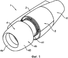
фиг.1 - схематическое аксонометрическое изображение заявляемой гондолы;figure 1 is a schematic axonometric image of the inventive nacelle;
фиг.2 - изображение, соответствующее гондоле с фиг.1, оснащенной рельсами согласно изобретению;figure 2 - image corresponding to the nacelle of figure 1, equipped with rails according to the invention;
фиг.3 - изображение гондолы с фиг.1 с подвижной конструкцией в открытом положении;figure 3 - image of the nacelle of figure 1 with a movable structure in the open position;
фиг.4 - изображение отдельно взятой подвижной конструкции;figure 4 - image of a single movable structure;
фиг.5 - вид в разрезе гондолы с фиг.1, снабженной ограничителем деформаций.figure 5 is a view in section of the nacelle of figure 1, equipped with a strain limiter.
Изображенная на фиг.1 заявляемая гондола 1 представляет собой трубчатый кожух турбореактивного двигателя 100, обеспечивающий направленную подачу воздушных потоков, создаваемых двигателем, образуя внутренние и внешние аэродинамические обводы, необходимые для достижения оптимальных эксплуатационных показателей.Depicted in figure 1, the inventive nacelle 1 is a tubular casing of a
В частности, гондола с фиг.1 предназначена для оснащения летательного аппарата административного или туристического типа. Двигательные установки летательных аппаратов указанных типов обычно закреплены на уровне фюзеляжа с помощью по существу горизонтального пилона 2 крепления.In particular, the gondola of FIG. 1 is intended to equip an aircraft of an administrative or tourist type. Propulsion systems of aircraft of these types are usually fixed at the level of the fuselage using a substantially
В общем случае конструкция гондолы 1 содержит переднюю секцию, образующую воздухозаборник 4, среднюю секцию 5, охватывающую вентилятор и корпус компрессора (не показаны) турбореактивного двигателя, и хвостовую секцию 6, выполненную с возможностью размещения в ней системы реверса тяги.In general, the structure of the nacelle 1 comprises a front section forming an air intake 4, a
Воздухозаборник 4 конструктивно разделен на две зоны: входную кромку 4а, выполненную таким образом, чтобы обеспечивать оптимальный захват и направление к турбореактивному двигателю 100 воздуха, необходимого для работы вентилятора и внутренних компрессоров турбореактивного двигателя, и расположенную ниже по потоку конструкцию 4b, которая содержит внешнюю панель 40 и внутреннюю панель 41, и на которой закреплена входная кромка 4а.The air intake 4 is structurally divided into two zones: the
В заявляемой гондоле 1 входная кромка 4а воздухозаборника объединена с внешней панелью 40 с образованием единой сдвижной детали. При этом внутренняя панель закреплена выше по потоку от кожуха вентилятора.In the inventive nacelle 1, the
Очевидно, что варианты осуществления гондолы не ограничиваются описываемым примером. В частности, одним из вариантов осуществления предусмотрена возможность того, что единая сдвижная деталь охватывает по меньшей мере участок внешней панели средней части 5 или даже внешнюю панель до хвостовой секции 6. Другим вариантом предусмотрена возможность того, что внутренняя панель 41 не является неподвижной и объединена с указанной сдвижной конструкцией.Obviously, embodiments of the gondola are not limited to the described example. In particular, one embodiment provides for the possibility that a single sliding part covers at least a portion of the outer panel of the
Следует отметить, что на внешней панели подвижной конструкции имеется вырез 10, охватывающий пилон 2 крепления при нахождении указанной сдвижной конструкции в закрытом положении, при этом обеспечена возможность помещения в указанный вырез передней части указанного пилона. Поскольку указанный вырез образует область соединения с пилоном 2 крепления, его можно снабдить кольцевыми уплотнительными прокладками 20.It should be noted that on the outer panel of the movable structure there is a
Область соединения прокладки 20 с пилоном 2 крепления предпочтительно выполнить с покатостью, обеспечивающей восстановление прокладки после деформаций, возникающих при выполнении действий по открыванию и закрыванию конструкции подвижного капота.The connection area of the
Подвижная конструкция установлена с возможностью сдвига на направляющих устройствах, в частности, на двух системах с рельсами 15 и ползунами 16, расположенных по обе стороны от пилона 2 крепления по возможности максимально близко к области соединения с указанным пилоном 2 крепления.The movable structure is mounted with the possibility of shear on guiding devices, in particular, on two systems with
Рельсы 15 жестко соединены с пилоном 2 крепления или, при необходимости, с кожухом вентилятора, при этом ползуны 16 жестко соединены с подвижной конструкцией. Разумеется, возможен также вариант с обратным расположением элементов.The
В частности, рельсы 15 прикреплены к пилону 2 крепления с помощью расположенной ниже по потоку металлической детали 34 и расположенной выше по потоку металлической детали 33, выполненных с возможностью входа и закрепления в пилоне 2 крепления.In particular, the
Тем самым системы с рельсами 15 и ползунами 16 обеспечивают улучшение противодействия нагрузкам и передачи нагрузок пилоном 2 крепления, и в значительной мере ограничивают деформации конструкции, в частности, при возникновении избыточного внутреннего давления в результате, например, разрыва трубопровода.Thus, systems with
При этом выше по потоку на обоих рельсах 15 имеется участок с консольным расположением относительно пилона 2 крепления и, соответственно, не опирающийся непосредственно на указанный пилон.Moreover, upstream on both
Для решения указанной проблемы и повышения прочности рельсов 15 при нахождении подвижного капота 4 в положении техобслуживания, расположенный выше по потоку не опорный участок каждого рельса 15 соединен с пилоном 2 крепления соединительной штангой 17, прикрепленной к передней металлической детали 33.To solve this problem and increase the strength of the
Кроме этого, для обеспечения постоянства расстояния между рельсами 15 на указанном расположенном выше по потоку не опорном участке, концы рельсов 15, расположенные выше по потоку, соединены друг с другом металлической деталью 38, которая и обеспечивает постоянство указанного расстояния.In addition, to ensure the constancy of the distance between the
Как показано на фиг.5, в конструкции предусмотрено наличие ограничителя 50 деформаций.As shown in figure 5, the design provides for the
Ограничитель 50 деформаций расположен по существу напротив пилона 2 крепления и содержит одинарную металлическую деталь 51, закрепленную на неподвижной конструкции, в частности, на внутренней панели 41, и раздвоенную металлическую деталь 52, закрепленную в подвижной конструкции, имеющей возможность сдвига, так, чтобы одинарная металлическая деталь 51 входила в раздвоенную металлическую деталь 52. При этом предусмотрено наличие зазора J, обеспечивающего отсутствие контакта между одинарной металлической деталью и раздвоенной металлической деталью при нахождении сдвижной конструкции в закрытом положении. Предусмотрен также вариант с противоположным расположением элементов, то есть с металлической деталью 51, установленной на подвижной конструкции капота, и металлической деталью 52 установленной на неподвижной конструкции.The
Дополнительно ограничитель деформаций 50 выполняет функцию средства центрирования.Additionally, the
В открытом положении, под действием, например ветра, или в результате другого воздействия, одинарная металлическая деталь 51 будет опираться на двойную металлическую деталь 52, обеспечивая тем самым противодействие нагрузкам.In the open position, under the influence of, for example, wind, or as a result of another effect, the
Несмотря на то, что для описания настоящего изобретения использован конкретный вариант осуществления, следует понимать, что настоящее изобретение ни в коей мере не ограничивается одним описанным вариантом осуществления и охватывает все технические решения, аналогичные описанным выше, а также их комбинации, не выходящие за рамки объема настоящего изобретения.Although a specific embodiment has been used to describe the present invention, it should be understood that the present invention is in no way limited to one described embodiment and covers all technical solutions similar to those described above, as well as combinations thereof, not beyond the scope of the present invention.
Claims (15)
Applications Claiming Priority (3)
| Application Number | Priority Date | Filing Date | Title |
|---|---|---|---|
| FR0806318A FR2938237B1 (en) | 2008-11-13 | 2008-11-13 | NACELLE FOR TURBOREACTOR WITH UPSTREATABLE TRANSLATABLE HOOD |
| FR08/06318 | 2008-11-13 | ||
| PCT/FR2009/001038 WO2010055216A1 (en) | 2008-11-13 | 2009-08-28 | Turbojet engine nacelle with translatable upstream cowl |
Publications (2)
| Publication Number | Publication Date |
|---|---|
| RU2011123685A RU2011123685A (en) | 2012-12-20 |
| RU2505458C2 true RU2505458C2 (en) | 2014-01-27 |
Family
ID=40679661
Family Applications (1)
| Application Number | Title | Priority Date | Filing Date |
|---|---|---|---|
| RU2011123685/11A RU2505458C2 (en) | 2008-11-13 | 2009-08-28 | Turbojet nacelle with sliding front cowl |
Country Status (8)
| Country | Link |
|---|---|
| US (1) | US9211956B2 (en) |
| EP (1) | EP2344385B8 (en) |
| CN (1) | CN102209667A (en) |
| BR (1) | BRPI0921772A2 (en) |
| CA (1) | CA2740824C (en) |
| FR (1) | FR2938237B1 (en) |
| RU (1) | RU2505458C2 (en) |
| WO (1) | WO2010055216A1 (en) |
Families Citing this family (9)
| Publication number | Priority date | Publication date | Assignee | Title |
|---|---|---|---|---|
| FR2906568B1 (en) * | 2006-10-02 | 2012-01-06 | Aircelle Sa | DEPOSITABLE AIR INTAKE STRUCTURE FOR TURBOJET NACELLE. |
| US8181905B2 (en) * | 2008-12-17 | 2012-05-22 | Rohr, Inc. | Aircraft engine nacelle with translating inlet cowl |
| US9783315B2 (en) * | 2012-02-24 | 2017-10-10 | Rohr, Inc. | Nacelle with longitudinal translating cowling and rotatable sleeves |
| FR2988778B1 (en) | 2012-03-29 | 2014-03-21 | Aircelle Sa | AIR INTAKE STRUCTURE OF LAMINAR TYPE TURBOREACTOR NACELLE AIRCRAFT |
| FR2999154B1 (en) * | 2012-12-12 | 2014-11-28 | Aircelle Sa | ASSEMBLY CENTER FOR TURBOREACTOR NACELLE |
| US10738737B2 (en) | 2016-11-18 | 2020-08-11 | Rohr, Inc. | Self-locking alignment at a nacelle interface |
| FR3094698B1 (en) | 2019-04-02 | 2022-09-09 | Safran Aircraft Engines | AIR INTAKE SLEEVE FOR A NACELLE OF AN AIRCRAFT PROPULSION ASSEMBLY |
| US11486307B2 (en) * | 2019-12-18 | 2022-11-01 | Rolls-Royce Deutschland Ltd & Co Kg | Aircraft comprising a gas turbine engine having an axially adjustable intake and a nacelle |
| FR3114849A1 (en) * | 2020-10-02 | 2022-04-08 | Airbus Operations | DOUBLE FLOW TURBOJET OF AN AIRCRAFT COMPRISING A HOOD ARTICULATED IN ROTATION AND A SYSTEM FOR DEPLOYING THE SAID HOOD |
Citations (5)
| Publication number | Priority date | Publication date | Assignee | Title |
|---|---|---|---|---|
| US5035379A (en) * | 1989-04-05 | 1991-07-30 | Societe Anonyme Dite Hispano-Suiza | Movable aircraft engine cowling |
| US5609313A (en) * | 1993-01-26 | 1997-03-11 | Short Brothers Plc | Aircraft propulsive power unit |
| SU1320997A1 (en) * | 1985-04-01 | 2004-12-20 | В.Ф. Гордеев | CASTLE OF THE AIRCRAFT |
| FR2906568A1 (en) * | 2006-10-02 | 2008-04-04 | Aircelle Sa | Nacelle for jet engine of aircraft, has acoustic shell fixed to median section to form fixed structure of nacelle, external panel connected to structure, and air inlet lip integrated to external panel so as to form unique dismountable piece |
| FR2914363A1 (en) * | 2007-03-26 | 2008-10-03 | Aircelle Sa | LOCKABLE GUIDE SYSTEM FOR MOBILE PART OF A NACELLE |
Family Cites Families (13)
| Publication number | Priority date | Publication date | Assignee | Title |
|---|---|---|---|---|
| US3460762A (en) * | 1967-07-24 | 1969-08-12 | Mc Donnell Douglas Corp | Thrust reverser roller latch |
| GB1418905A (en) * | 1972-05-09 | 1975-12-24 | Rolls Royce | Gas turbine engines |
| US4206893A (en) * | 1978-09-27 | 1980-06-10 | The Boeing Company | Seal closure for slot in engine mounting strut |
| US4555078A (en) * | 1983-12-27 | 1985-11-26 | Societe Belge D'exploitation De La Navigation Aerienne (Sabena) | Apparatus for the suspension of an aircraft engine cowling |
| US4688757A (en) | 1986-08-11 | 1987-08-25 | Dresser Industries, Inc. | Soft seat Y pattern globe valve |
| FR2757823B1 (en) * | 1996-12-26 | 1999-03-12 | Aerospatiale | LAMINARY FLOW TURBOREACTOR BASKET |
| US6340135B1 (en) * | 2000-05-30 | 2002-01-22 | Rohr, Inc. | Translating independently mounted air inlet system for aircraft turbofan jet engine |
| FR2821892B1 (en) * | 2001-03-08 | 2003-06-13 | Hispano Suiza Sa | SYSTEM FOR ACTUATING THE MOBILE COVERING OF A DRIVE INVERTER IN A TURBOJET |
| US7588212B2 (en) | 2003-07-08 | 2009-09-15 | Rohr Inc. | Method and apparatus for noise abatement and ice protection of an aircraft engine nacelle inlet lip |
| FR2898868B1 (en) | 2006-03-24 | 2008-12-12 | Aircelle Sa | STRUCTURE FOR AIR ENTRANCE LAUNCHER WITH ELECTRIC DEFROSTING |
| FR2901244B1 (en) * | 2006-05-16 | 2009-01-09 | Airbus France Sas | DEVICE FOR JOINING DOORS OF AN AIRCRAFT NACELLE AND NACELLE EQUIPPED WITH SAID ARTICULATION DEVICE |
| FR2925877B1 (en) * | 2007-12-26 | 2009-12-04 | Aircelle Sa | INSTALLATION OF GUIDING SYSTEM ON AN AIRCRAFT NACELLE. |
| US8181905B2 (en) * | 2008-12-17 | 2012-05-22 | Rohr, Inc. | Aircraft engine nacelle with translating inlet cowl |
-
2008
- 2008-11-13 FR FR0806318A patent/FR2938237B1/en not_active Expired - Fee Related
-
2009
- 2009-08-28 WO PCT/FR2009/001038 patent/WO2010055216A1/en active Application Filing
- 2009-08-28 BR BRPI0921772A patent/BRPI0921772A2/en not_active IP Right Cessation
- 2009-08-28 RU RU2011123685/11A patent/RU2505458C2/en not_active IP Right Cessation
- 2009-08-28 CA CA2740824A patent/CA2740824C/en not_active Expired - Fee Related
- 2009-08-28 CN CN2009801446888A patent/CN102209667A/en active Pending
- 2009-08-28 EP EP09737037.3A patent/EP2344385B8/en not_active Not-in-force
- 2009-08-28 US US13/129,290 patent/US9211956B2/en not_active Expired - Fee Related
Patent Citations (5)
| Publication number | Priority date | Publication date | Assignee | Title |
|---|---|---|---|---|
| SU1320997A1 (en) * | 1985-04-01 | 2004-12-20 | В.Ф. Гордеев | CASTLE OF THE AIRCRAFT |
| US5035379A (en) * | 1989-04-05 | 1991-07-30 | Societe Anonyme Dite Hispano-Suiza | Movable aircraft engine cowling |
| US5609313A (en) * | 1993-01-26 | 1997-03-11 | Short Brothers Plc | Aircraft propulsive power unit |
| FR2906568A1 (en) * | 2006-10-02 | 2008-04-04 | Aircelle Sa | Nacelle for jet engine of aircraft, has acoustic shell fixed to median section to form fixed structure of nacelle, external panel connected to structure, and air inlet lip integrated to external panel so as to form unique dismountable piece |
| FR2914363A1 (en) * | 2007-03-26 | 2008-10-03 | Aircelle Sa | LOCKABLE GUIDE SYSTEM FOR MOBILE PART OF A NACELLE |
Also Published As
| Publication number | Publication date |
|---|---|
| CA2740824A1 (en) | 2010-05-20 |
| US9211956B2 (en) | 2015-12-15 |
| WO2010055216A1 (en) | 2010-05-20 |
| FR2938237A1 (en) | 2010-05-14 |
| FR2938237B1 (en) | 2011-05-20 |
| CA2740824C (en) | 2017-01-03 |
| EP2344385B8 (en) | 2017-03-22 |
| EP2344385B1 (en) | 2016-12-21 |
| RU2011123685A (en) | 2012-12-20 |
| BRPI0921772A2 (en) | 2016-01-05 |
| US20110219783A1 (en) | 2011-09-15 |
| CN102209667A (en) | 2011-10-05 |
| EP2344385A1 (en) | 2011-07-20 |
Similar Documents
| Publication | Publication Date | Title |
|---|---|---|
| RU2505458C2 (en) | Turbojet nacelle with sliding front cowl | |
| EP2202153B1 (en) | Monolithic structure for mounting aircraft engine | |
| US8328504B2 (en) | Aeroengine drain assembly | |
| RU2440279C2 (en) | Power plant integrated with aircraft suspension | |
| US6892526B2 (en) | Cowl structure for a gas turbine engine | |
| US8668441B2 (en) | Deformable structural framework for a turbofan nacelle | |
| US8876042B2 (en) | Integrated nacelle assembly | |
| US7007890B2 (en) | Turbojet designed to be fixed onto the AFT part of the fuselage of an aircraft, in upper position | |
| EP2792597B1 (en) | Inner cowl structure for aircraft turbine engine | |
| US20080073460A1 (en) | Aeroengine mount | |
| CA2926862C (en) | Turbofan bypass air cooled oil cooler fairings | |
| RU2470839C2 (en) | System of guides for turbojet nacelle | |
| EP2718185B1 (en) | System and method for mounting an aircraft engine | |
| US20100040466A1 (en) | Bypass turbojet engine nacelle | |
| EP3112605B1 (en) | Seals for gas turbine engine core nacelle cowlings | |
| US20090165463A1 (en) | Fixing System for a Component of a Turbojet Pod | |
| US20170137134A1 (en) | Propulsion assembly for an aircraft, comprising a gas generator, two offset fans and an air inlet sleeve | |
| RU2492117C2 (en) | Turbojet fastener assembly | |
| EP3254953A1 (en) | Thermal insulaton blanket | |
| RU2509688C2 (en) | Turbojet nacelle | |
| US20110220218A1 (en) | Turbojet engine nacelle | |
| US20240026798A1 (en) | Propulsion unit for an aircraft and method for mounting same | |
| CN117940342A (en) | Nacelle for an aircraft propulsion unit comprising an access space enclosed by a tangential grip hood |
Legal Events
| Date | Code | Title | Description |
|---|---|---|---|
| MM4A | The patent is invalid due to non-payment of fees |
Effective date: 20150829 |