RU2503573C2 - Truck coupler - Google Patents
Truck coupler Download PDFInfo
- Publication number
- RU2503573C2 RU2503573C2 RU2010142927/11A RU2010142927A RU2503573C2 RU 2503573 C2 RU2503573 C2 RU 2503573C2 RU 2010142927/11 A RU2010142927/11 A RU 2010142927/11A RU 2010142927 A RU2010142927 A RU 2010142927A RU 2503573 C2 RU2503573 C2 RU 2503573C2
- Authority
- RU
- Russia
- Prior art keywords
- locking
- locking element
- bolt
- locking bolt
- actuator
- Prior art date
Links
- 230000008878 coupling Effects 0.000 claims description 29
- 238000010168 coupling process Methods 0.000 claims description 29
- 238000005859 coupling reaction Methods 0.000 claims description 29
- 230000000903 blocking effect Effects 0.000 claims description 6
- 238000005266 casting Methods 0.000 claims description 4
- 230000003993 interaction Effects 0.000 claims description 3
- 230000003287 optical effect Effects 0.000 claims description 3
- 229910000831 Steel Inorganic materials 0.000 claims description 2
- 239000002184 metal Substances 0.000 claims description 2
- 239000010959 steel Substances 0.000 claims description 2
- 230000000717 retained effect Effects 0.000 abstract description 3
- 230000000694 effects Effects 0.000 abstract 1
- 239000000126 substance Substances 0.000 abstract 1
- 230000008901 benefit Effects 0.000 description 4
- 230000006378 damage Effects 0.000 description 3
- 230000007246 mechanism Effects 0.000 description 3
- 238000000034 method Methods 0.000 description 3
- 230000008569 process Effects 0.000 description 3
- 230000004044 response Effects 0.000 description 3
- 238000012544 monitoring process Methods 0.000 description 2
- 206010010774 Constipation Diseases 0.000 description 1
- 230000004888 barrier function Effects 0.000 description 1
- 239000012634 fragment Substances 0.000 description 1
- 238000003780 insertion Methods 0.000 description 1
- 230000037431 insertion Effects 0.000 description 1
- 210000003127 knee Anatomy 0.000 description 1
- 239000000463 material Substances 0.000 description 1
- 210000000056 organ Anatomy 0.000 description 1
- 230000011664 signaling Effects 0.000 description 1
- 230000001960 triggered effect Effects 0.000 description 1
Images


Classifications
-
- B—PERFORMING OPERATIONS; TRANSPORTING
- B62—LAND VEHICLES FOR TRAVELLING OTHERWISE THAN ON RAILS
- B62D—MOTOR VEHICLES; TRAILERS
- B62D53/00—Tractor-trailer combinations; Road trains
- B62D53/04—Tractor-trailer combinations; Road trains comprising a vehicle carrying an essential part of the other vehicle's load by having supporting means for the front or rear part of the other vehicle
- B62D53/08—Fifth wheel traction couplings
- B62D53/10—Fifth wheel traction couplings with means for preventing accidental uncoupling
-
- B—PERFORMING OPERATIONS; TRANSPORTING
- B62—LAND VEHICLES FOR TRAVELLING OTHERWISE THAN ON RAILS
- B62D—MOTOR VEHICLES; TRAILERS
- B62D53/00—Tractor-trailer combinations; Road trains
- B62D53/04—Tractor-trailer combinations; Road trains comprising a vehicle carrying an essential part of the other vehicle's load by having supporting means for the front or rear part of the other vehicle
- B62D53/08—Fifth wheel traction couplings
Landscapes
- Engineering & Computer Science (AREA)
- Chemical & Material Sciences (AREA)
- Combustion & Propulsion (AREA)
- Transportation (AREA)
- Mechanical Engineering (AREA)
- Lock And Its Accessories (AREA)
- Steering-Linkage Mechanisms And Four-Wheel Steering (AREA)
- Clamps And Clips (AREA)
Abstract
Description
Изобретение относится к седельно-сцепному устройству, содержащему плиту, в которой выполнено отверстие для ввода шкворня, по меньшей мере, одно цельное запорное устройство для фиксации шкворня и воздействующий на запорное устройство фиксатор, движущийся из запирающего положения в отпирающее положение и обратно.The invention relates to a fifth wheel coupling device comprising a plate in which a hole is provided for introducing a pin, at least one integral locking device for fixing the pin and a latch acting on the locking device moving from the locking position to the unlocking position and vice versa.
Транспортные средства хозяйственного назначения состоят, как правило, из тягача и одного или нескольких прицепов. В случае сочлененного автопоезда речь идет об автомобиле с прицепом, а в случае седельного автопоезда - о тягаче и полуприцепе.Economic vehicles consist, as a rule, of a tractor and one or more trailers. In the case of an articulated road train, we are talking about a car with a trailer, and in the case of a saddle road train - about a tractor and a semi-trailer.
Припаркованные и ведомые части транспортного средства могут быть защищены от угона механическими устройствами. Моторизованные части грузового автомобиля в большинстве случаев также защищены от взлома и угона, например посредством иммобилайзеров или охранной сигнализации. Если обе части транспортного средства сцеплены между собой, то определенная защита от угона обеспечивается этими системами для всего седельного автопоезда, поскольку расцепление возможно только за счет движения обеих частей транспортного средства по отношению друг к другу.Parked and driven parts of the vehicle can be protected against theft by mechanical devices. The motorized parts of the truck in most cases are also protected from hacking and theft, for example through immobilizers or burglar alarms. If both parts of the vehicle are interlocked, a certain protection against theft is provided by these systems for the entire road train, since disengagement is possible only due to the movement of both parts of the vehicle in relation to each other.
Однако, несмотря на современные технические средства защиты, число угонов, в которых ведущее транспортное средство отделяется от прицепа или полуприцепа, который затем угоняется, непрерывно растет. Поэтому желательно создать устройства и системы, которые должны предотвратить несанкционированное отцепление полуприцепа или, по меньшей мере, затруднить этот процесс так, чтобы даже попытка угона с самого начала представлялась бесперспективной.However, despite the modern technical means of protection, the number of thefts in which the driving vehicle is separated from the trailer or semi-trailer, which is then stolen, is constantly growing. Therefore, it is desirable to create devices and systems that should prevent the unauthorized uncoupling of the semi-trailer or at least complicate this process so that even an attempt to hijack from the very beginning seems futile.
Из документа WO 03/043838 А2 известно противоугонное устройство для седельно-сцепных устройств, содержащее исполнительное устройство с блокировочным штифтом. Седельно-сцепное устройство содержит запорный крюк с предохранительным ригелем, который посредством рычажного механизма приводится в действие от руки с помощью тяги.An anti-theft device for fifth wheel coupling is known from WO 03/043838 A2, comprising an actuator with a locking pin. The fifth wheel includes a locking hook with a safety bolt, which, by means of a lever mechanism, is manually actuated by means of a rod.
Противоугонное устройство предусматривает, что блокировочный штифт вводится либо в траекторию движения предохранительного ригеля, либо в траекторию движения компонентов рычажного механизма для приведения в действие предохранительного ригеля, так что последний не может двигаться из своего запирающего положения в отпирающее положение.The anti-theft device provides that the locking pin is inserted either into the trajectory of the safety bolt or into the trajectory of the components of the link mechanism to actuate the safety bolt, so that the latter cannot move from its locking position to the unlocked position.
Противоугонное устройство содержит приемник, посредством которого можно управлять исполнительным устройством. Противоугонное устройство подключено к системе GPS тягача. Если транспортное средство движется не по заданному маршруту, то система GPS обнаруживает это и посылает приемнику сигнал на срабатывание противоугонного устройства, в ответ на что блокировочный штифт приводится в положение блокирования.The anti-theft device contains a receiver through which you can control the actuator. The anti-theft device is connected to the GPS system of the tractor. If the vehicle does not move along the specified route, the GPS system detects this and sends a signal to the receiver to activate the anti-theft device, in response to which the locking pin is set to the locking position.
Согласно другому предпочтительному варианту выполнения, противоугонным устройством можно управлять также по Интернету посредством внешнего ПК через бортовой компьютер тягача.According to another preferred embodiment, the anti-theft device can also be controlled via the Internet via an external PC via the on-board computer of the tractor.
Попытки манипулирования седельно-сцепным устройством также обнаруживаются противоугонным устройством, которое в ответ на это самопроизвольно срабатывает и, тем самым, переходит также в положение блокирования.Attempts to manipulate the fifth wheel coupling are also detected by an anti-theft device, which in response to this spontaneously triggers and, thus, also switches to the blocking position.
В документе WO 03/044627 описаны другие охранные системы, причем проверяется правомочие водителя путем ввода кода. В случае пренебрежения этим или отклонения от маршрута движения происходит автоматическое вмешательство в функции транспортного средства.Other security systems are described in document WO 03/044627, the driver’s competency being verified by entering a code. In case of neglect or deviation from the route of movement, automatic intervention in the functions of the vehicle occurs.
В документе WO 2005/028290 А1 раскрыто седельно-сцепное устройство с противоугонным устройством, в котором блокировочный штифт воздействует непосредственно на запорный крюк и фиксирует его. Посредством тяги блокировка может быть устранена. Расцепление тягача и полуприцепа силовым путем в этом случае предотвратить нельзя, поскольку при резком трогании с места седельного автопоезда с повреждением или даже разрушением противоугонного устройства запорный крюк может повернуться в отпирающее положение.WO 2005/028290 A1 discloses a fifth wheel coupling with an anti-theft device in which a locking pin acts directly on the locking hook and locks it. Through traction, the lock can be removed. The decoupling of the tractor and semitrailer by force cannot be prevented in this case, since when the truck is suddenly pulled away from the seat with damage or even destruction of the anti-theft device, the locking hook can turn into the unlocking position.
Противоугонное устройство содержит блок управления в кабине тягача, в который для отключения может быть введен числовой код. С блоком управления соединены датчики и индикаторы для контроля за седельно-сцепным устройством.The anti-theft device contains a control unit in the tractor cab, into which a numerical code can be entered for shutdown. Sensors and indicators are connected to the control unit for monitoring the fifth wheel coupling.
В документе DE 19516101 А1 описано противоугонное устройство для прицепленного полуприцепа. Для его защиты от угона в результате отцепления седельно-сцепное устройство содержит замок, посредством которого происходит управление аксиально-подвижным толкателем. Толкатель воздействует непосредственно на блокировочный элемент запорного крюка, когда тот находится в запирающем положении. Расположение противоугонного устройства выбрано так, что толкатель нагружается давлением. Блокирование приводимого в действие от руки запорного крюка имеет то преимущество, что при резкой нагрузке или перегрузке ручного привода его более слабые в сечении звенья ломаются, а блокирование запорного крюка в любом случае сохраняется. При попытке разблокирования силовым путем все детали противоугонного устройства нагружаются давлением, в результате чего относительно небольшие сечения обеспечивают требуемую функциональную надежность.DE 195 16 101 A1 describes an anti-theft device for a towed semi-trailer. To protect it from theft as a result of uncoupling, the fifth wheel coupling contains a lock, by means of which an axially movable pusher is controlled. The pusher acts directly on the locking element of the locking hook when it is in the locking position. The location of the anti-theft device is selected so that the pusher is loaded with pressure. Blocking a hand-operated locking hook has the advantage that, under a sharp load or overload of a manual drive, its weaker sections break down, and locking of the locking hook is retained in any case. When you try to unblock it by force, all parts of the anti-theft device are loaded with pressure, as a result of which relatively small sections provide the required functional reliability.
Противоугонные устройства воздействуют, как правило, на запорную систему седельно-сцепного устройства и должны блокировать ее, так что отпереть ее нельзя. Само противоугонное устройство не обеспечивает механической защиты, которая могла бы предотвратить отцепление полуприцепа. Причина заключается, в том числе, в том, что противоугонное устройство или детали, блокирующие запорную систему, выполнены недостаточно стабильными и стойкими, чтобы предотвратить ее отпирание силовым путем.Anti-theft devices act, as a rule, on the locking system of the fifth wheel coupling and must block it, so that it cannot be unlocked. The anti-theft device itself does not provide mechanical protection that could prevent the semitrailer from unhitching. The reason is, inter alia, that the anti-theft device or parts blocking the locking system are not stable and resistant enough to prevent it being unlocked by force.
Задачей изобретения является оснащение седельно-сцепного устройства предохранительным устройством, которое, при необходимости, может использоваться вместе с противоугонным устройством и обеспечивает дополнительную защиту от несанкционированного отцепления полуприцепа.The objective of the invention is to equip the fifth wheel coupling with a safety device, which, if necessary, can be used together with an anti-theft device and provides additional protection against unauthorized uncoupling of the semi-trailer.
Эта задача решается посредством седельно-сцепного устройства, охарактеризованного признаками п.1 формулы. Седельно-сцепное устройство характеризуется тем, что предусмотрено предохранительное устройство со стопорным элементом, движущимся из исходного положения в запирающее положение и обратно, причем стопорный элемент, по меньшей мере, в запирающем положении направлен в отверстие для ввода и фиксируется в этом положении, если фиксатор несанкционированным образом находится в отпирающем положении.This problem is solved by means of a fifth wheel coupling, characterized by the features of
Стопорный элемент дополнительного предохранительного устройства образует механический стопор, который блокирует выдвигание шкворня даже тогда, когда, например, противоугонное устройство было силовым путем отключено и/или отпирание запорного устройства происходит несанкционированным образом. Благодаря стопорному элементу создан дополнительный механический барьер, выполненный настолько стабильным, что он противостоит манипулированию силовым путем.The locking element of the additional safety device forms a mechanical stop that blocks the extension of the kingpin even when, for example, the anti-theft device has been disconnected by force and / or the locking device is unlocked in an unauthorized manner. Thanks to the locking element, an additional mechanical barrier is created, made so stable that it resists manipulation by force.
Фиксация стопорного элемента в его запирающем положении имеет преимущество, заключающееся в предотвращении его возврата с исходное положение за счет несанкционированного приведения в действие запорной системы, в результате чего потенциальному угонщику при определенных обстоятельствах удалось бы, тем не менее, освободить отверстие для ввода, чтобы обеспечить выдвигание шкворня.Fixing the locking element in its locking position has the advantage of preventing it from returning to its original position due to the unauthorized actuation of the locking system, as a result of which, under certain circumstances, the potential hijacker would nevertheless clear the entry hole to allow for extension king pin.
Стопорный элемент, предпочтительно, расположен скрыто внутри седельно-сцепного устройства и, тем самым, недоступен извне. Предпочтительно он может приводиться в действие не вручную.The locking element is preferably located hidden inside the fifth wheel coupling and thus is not accessible from the outside. Preferably, it may not be manually actuated.
Запорным устройством может быть поворотный запорный крюк, или оно может состоять из двух или более компонентов, которые в блокированном положении охватывают шкворень.The locking device may be a rotary locking hook, or it may consist of two or more components that, in a locked position, surround the king pin.
В качестве фиксатора, который фиксирует и, тем самым, блокирует запорное устройство в его запирающем положении, может быть предусмотрен в зависимости от выполнения запорного устройства запорный ригель или запорный зажим.Depending on the design of the locking device, a locking bolt or locking clip may be provided as a latch that locks and thereby locks the locking device in its locking position.
Согласно первому варианту выполнения, фиксатором является запорный ригель, с которым взаимодействует стопорный элемент. Последний, предпочтительно, контактирует с запорным ригелем и в случае несанкционированного приведения в действие запорной системы связан с движением запорного ригеля. Если запорный ригель несанкционированным образом движется в отпирающее положение, то стопорный элемент следует за ним и движется в свое запирающее положение.According to the first embodiment, the latch is a locking bolt with which the locking element interacts. The latter, preferably, is in contact with the locking bolt and in the case of unauthorized actuation of the locking system is associated with the movement of the locking bolt. If the locking bolt moves in the unlocking position in an unauthorized manner, then the locking element follows it and moves to its locking position.
Предпочтительно стопорный элемент расположен напротив запорного ригеля. При этом запорный ригель и стопорный элемент расположены, предпочтительно, на одной общей оси. Если запорный ригель расположен, например, по одну сторону отверстия для ввода, то стопорный элемент - по другую. В этом случае острия запорного ригеля и стопорного элемента противоположны друг другу.Preferably, the locking element is located opposite the locking bolt. The locking bolt and the locking element are preferably located on the same common axis. If the locking bolt is located, for example, on one side of the entry hole, then the locking element is on the other. In this case, the tips of the locking bolt and the locking element are opposite to each other.
Стопорный элемент выполнен, предпочтительно, в виде стопорного ригеля. Он имеет то преимущество, что представляет собой стабильный механический конструктивный элемент, который может оказывать нежелательно выдвигающемуся шкворню достаточное механическое сопротивление.The locking element is preferably made in the form of a locking bolt. It has the advantage of being a stable mechanical component that can provide undesirable retractable kingpin with sufficient mechanical resistance.
Стопорный ригель перемещается, предпочтительно, в том же направлении, что и запорный ригель. Если запорный ригель движется в отпирающее положение, то стопорный ригель входит в отверстие для ввода и занимает в нем положение запорного ригеля. Процесс движения упрощается, а занимаемое стопорным элементом или стопорным ригелем место уменьшается.The locking bolt moves preferably in the same direction as the locking bolt. If the locking bolt moves to the unlocked position, the locking bolt enters the entry hole and occupies the position of the locking bolt therein. The movement process is simplified, and the space occupied by the locking element or locking bolt is reduced.
Предпочтительно, стопорный ригель разъемно закреплен на запорном ригеле. Стопорный ригель закреплен на запорном ригеле, если тот движется несанкционированным образом. Стопорный ригель тянется запорным ригелем в положение блокирования. Стопорный ригель отделяется от запорного ригеля, если тот приводится в действие несанкционированным образом. Стопорный ригель остается тогда в своем исходном положении.Preferably, the locking bolt is detachably fixed to the locking bolt. The locking bolt is mounted on the locking bolt if it moves in an unauthorized way. The locking bolt extends with the locking bolt to the locked position. The locking bolt is separated from the locking bolt if it is actuated in an unauthorized manner. The locking bolt then remains in its original position.
Предпочтительно, острие стопорного ригеля разъемно закреплено на острие запорного ригеля.Preferably, the tip of the locking bolt is detachably fixed to the tip of the locking bolt.
Для создания такого разъемного закрепления, согласно одному предпочтительному варианту, предусмотрено, что запорный ригель и/или стопорный ригель содержит, по меньшей мере, один магнит. Сила магнита или магнитов рассчитана так, что запорный ригель может, с одной стороны, подхватывать стопорный ригель, а, с другой стороны, стопорный ригель может отделяться от запорного ригеля, если тот движется санкционированным образом, а стопорный ригель фиксирован в своем исходном положении.To create such a detachable fastening, according to one preferred embodiment, it is provided that the locking bolt and / or the locking bolt contains at least one magnet. The strength of the magnet or magnets is designed so that the locking bolt can, on the one hand, pick up the locking bolt, and, on the other hand, the locking bolt can be separated from the locking bolt if it moves in an authorized manner, and the locking bolt is fixed in its original position.
Запорный и стопорный ригели могут содержать, согласно другому предпочтительному варианту, фиксирующие органы, которые входят друг в друга, а, при необходимости, могут также снова отделяться друг от друга.The locking and locking bolts may contain, according to another preferred embodiment, the locking bodies that enter into each other, and, if necessary, can also be separated again from each other.
В качестве фиксирующих органов предусмотрены фиксирующие носики и фиксирующие крюки.As the locking organs provided locking nozzles and locking hooks.
Предпочтительно, стопорный элемент содержит пружину, которая прижимает его к запорному ригелю в запирающем положении последнего. Если запорный ригель несанкционированным образом оттягивается, то стопорный ригель непосредственно следует за ним и занимает положение запорного ригеля в отверстии для ввода.Preferably, the locking element comprises a spring which presses it against the locking bolt in the locking position of the latter. If the locking bolt is pulled out in an unauthorized way, the locking bolt immediately follows it and occupies the position of the locking bolt in the entry hole.
Стопорный элемент выполнен с возможностью фиксации в своем исходном положении. Фиксация стопорного элемента в его исходном положении необходима, чтобы запорный ригель при санкционированном приведении в действие мог отделиться от стопорного элемента.The locking element is made with the possibility of fixing in its original position. Fixing the locking element in its initial position is necessary so that the locking bolt, when authorized to act, can separate from the locking element.
Средства для фиксации и освобождения стопорного элемента включают в себя преимущественно первое исполнительное устройство с блокировочным органом и, по меньшей мере, одним актуатором. Последний представляет собой преимущественно электрический, пневматический или гидравлический актуатор.Means for fixing and releasing the locking element include primarily a first actuator with a locking member and at least one actuator. The latter is primarily an electric, pneumatic or hydraulic actuator.
В качестве блокировочного органа может быть предусмотрен блокировочный штифт или собачка.As a locking member, a locking pin or a pawl may be provided.
Блокировочный штифт, предпочтительно, перемещается перпендикулярно направлению движения стопорного элемента.The locking pin preferably moves perpendicular to the direction of movement of the locking element.
Чтобы блокировочный орган мог эффективно фиксировать стопорный элемент, предпочтительно предусмотрена, по меньшей мере, одна первая выемка, в которую может входить блокировочный орган.In order for the locking member to be able to effectively lock the locking member, at least one first recess is preferably provided in which the locking member can enter.
Чтобы исполнительное устройство можно было включить нужным образом, оно подключено к устройству управления. Последнее может содержать блок ввода, например, команд, числовых кодов и т.п. С помощью устройства управления водитель может определить, происходит ли отпирание запорного ригеля санкционированным или несанкционированным образом.So that the actuator can be turned on as needed, it is connected to the control device. The latter may contain an input unit, for example, commands, numerical codes, etc. Using the control device, the driver can determine whether the locking bolt is unlocked in an authorized or unauthorized manner.
Согласно одному особо предпочтительному варианту выполнения, устройство управления может быть подключено к устройству контроля, например устройству контроля состояния запирания седельно-сцепного устройства. В зависимости от состояния запирания эта информация может использоваться для включения предохранительного устройства.According to one particularly preferred embodiment, the control device can be connected to a control device, for example a device for monitoring the locking state of the fifth wheel coupling. Depending on the locking status, this information can be used to activate a safety device.
Устройство контроля может представлять собой или содержать противоугонное устройство, чтобы обнаружить несанкционированное отпирание запорного крюка. Такое противоугонное устройство может обычным образом воздействовать на запорный крюк и обнаруживать его несанкционированное отпирание. Поэтому противоугонное устройство содержит, предпочтительно, устройство на запорном крюке, например с блокировочным штифтом, которое связано с индикаторным блоком и/или блоком управления в кабине водителя. Речь может идти, например, о противоугонном устройстве, описанном в WO 2005/028290 А1.The control device may be or comprise an anti-theft device to detect unauthorized unlocking of the locking hook. Such an anti-theft device can normally act on the locking hook and detect its unauthorized unlocking. Therefore, the anti-theft device preferably comprises a device with a locking hook, for example with a locking pin, which is connected to an indicator unit and / or a control unit in the driver's cab. We can talk, for example, about the anti-theft device described in WO 2005/028290 A1.
Стопорный элемент может регулироваться в своем исходном положении. Регулировка может понадобиться, если запорный ригель имеет следы износа и отсутствует предусмотренный контакт между ним и стопорным элементом.The locking element can be adjusted in its original position. Adjustment may be necessary if the locking bolt has signs of wear and there is no intended contact between it and the locking element.
Предпочтительно, предусмотрено второе исполнительное устройство с блокирующим органом и актуатором для фиксации запорного ригеля в его запирающем положении. Это второе исполнительное устройство может быть, например, составной частью отдельного противоугонного устройства или может быть также подключено к устройству управления. За счет этого можно посредством устройства управления не только активировать предохранительное устройство, но и в качестве дополнительной меры блокировать запорный ригель.Preferably, a second actuator is provided with a locking member and an actuator for fixing the locking bolt in its locking position. This second actuator can, for example, be part of a separate anti-theft device or can also be connected to a control device. Due to this, it is possible not only to activate the safety device via the control device, but also to block the locking bolt as an additional measure.
Согласно другому варианту выполнения, стопорный элемент расположен на расстоянии от запорного устройства и фиксатора. При этом стопорный элемент не взаимодействует с запорным ригелем. Этот вариант имеет то преимущество, что на функцию запорного механизма не влияет предохранительное устройство. Все функции запора сохраняются.According to another embodiment, the locking element is located at a distance from the locking device and the latch. However, the locking element does not interact with the locking bolt. This option has the advantage that the safety device does not affect the function of the locking mechanism. All constipation functions are retained.
Стопорный элемент расположен внутри второй половины отверстия для ввода. Она обозначает в направлении ввода последнюю половину отверстия. В этой зоне отверстие для ввода уже сужено настолько, что не слишком большого стопорного элемента достаточно, чтобы блокировать его.The locking element is located inside the second half of the entry hole. It marks the last half of the hole in the direction of entry. In this zone, the entry hole is already narrowed so that not too large locking element is enough to block it.
Стопорный элемент, предпочтительно, удерживается в запирающем положении посредством второй пружины и движется входящим или выходящим шкворнем против ее усилия, освобождая отверстие для ввода. Стопорный элемент фиксируется в запирающем положении.The locking element is preferably held in the locked position by the second spring and moves by the inlet or outlet pin against its force, freeing the entry hole. The locking element is locked in the locking position.
В этом варианте выполнения стопорный элемент постоянно входит в отверстие для ввода, так что стопорящее и исходное положения совпадают. Запирание отверстия для ввода достигается за счет того, что в запирающем положении стопорный элемент также фиксируется и не может двигаться выходящим шкворнем. Это гарантирует защиту при несанкционированном отпирании запорной системы шкворня.In this embodiment, the locking element constantly enters the entry hole so that the locking and initial positions coincide. The locking of the entry hole is achieved due to the fact that in the locking position, the locking element is also fixed and cannot move outgoing pin. This ensures protection against unauthorized unlocking of the king pin locking system.
Также в этом варианте выполнения предпочтительно, если стопорным элементом является стопорный ригель. Он расположен с возможностью движения перпендикулярно продольной оси отверстия для ввода.Also in this embodiment, it is preferable if the locking element is a locking bolt. It is arranged to move perpendicular to the longitudinal axis of the entry hole.
Для фиксации и освобождения стопорного элемента, как и в первом варианте, предусмотрено исполнительное устройство, содержащее блокировочный орган, и, по меньшей мере, один актуатор. Этим исполнительным устройством является, предпочтительно, блокировочное устройство. Оно выполнено так, что после ввода шкворня стопорный элемент автоматически блокируется в своем запирающем положении.For fixing and releasing the locking element, as in the first embodiment, an actuator is provided comprising a locking member and at least one actuator. This actuator is preferably a locking device. It is designed so that after the pin is inserted, the locking element is automatically locked in its locking position.
Блокировочное устройство содержит блокировочный элемент и третью пружину, которая удерживает блокировочный элемент в блокирующем положении.The locking device comprises a locking element and a third spring that holds the locking element in the locking position.
Блокировочный элемент, предпочтительно, содержит актуатор, который перемещает его против усилия третьей пружины из блокирующего положения в освобождающее положение.The locking element preferably comprises an actuator which moves it against the force of the third spring from the locking position to the released position.
Стопорный элемент, предпочтительно, содержит собачку, взаимодействующую с блокировочным элементом. Эта собачка фиксирует блокировочный элемент против усилия третьей пружины. Если стопорный элемент за счет вводимого шкворня движется обратно против усилия третьей пружины, то натяженный ею блокировочный элемент отпускается собачкой, в результате чего он может быть прижат к стопорному элементу. Блокировочный элемент движется преимущественно перпендикулярно направлению движения стопорного элемента.The locking element preferably comprises a dog cooperating with the locking element. This dog locks the locking element against the efforts of the third spring. If the locking element moves back against the force of the third spring due to the inserted king pin, then the locking element tensioned by it is released by the dog, as a result of which it can be pressed against the locking element. The locking element moves mainly perpendicular to the direction of movement of the locking element.
Предпочтительно, если актуатор блокировочного устройства также подключен к устройству управления, чтобы управлять им нужным образом.Preferably, if the actuator of the locking device is also connected to the control device in order to control it as needed.
Предпочтительно, по меньшей мере, одно из исполнительных устройств расположено на седельно-сцепном устройстве, так что видно извне. Дополнительно исполнительное устройство может содержать оптическое и/или акустическое устройство. Эти меры должны указывать потенциальным угонщикам на наличие предохранительного устройства и, тем самым, удержать их от кражи полуприцепа.Preferably, at least one of the actuators is located on the fifth wheel coupling, so that it is visible from the outside. Additionally, the actuator may include an optical and / or acoustic device. These measures should indicate to potential hijackers the presence of a safety device and, thereby, prevent them from stealing the semi-trailer.
Исполнительное устройство или устройства расположены соответственно в корпусе, причем он в одном варианте привинчен к верхней стороне плиты седельно-сцепного устройства. Отвинтить винты невозможно, если полуприцеп прицеплен.The actuator or devices are respectively located in the housing, and in one embodiment it is screwed to the upper side of the plate of the fifth wheel coupling. It is not possible to unscrew the screws if the trailer is attached.
Корпус может быть приварен или приклепан к плите седельно-сцепного устройства. В качестве материала корпуса служит преимущественно отливка, стальная отливка, высокопрочный легкий металл или высокопрочный пластик, чтобы предотвратить разрушение корпуса в результате силового воздействия.The housing can be welded or riveted to the fifth wheel plate. The material of the casing is mainly casting, steel casting, high-strength light metal or high-strength plastic to prevent destruction of the casing as a result of force.
В качестве актуаторов подходят, в частности, катушки, цилиндры, серводвигатели или гидроприводы.As actuators, in particular, coils, cylinders, servomotors or hydraulic drives are suitable.
Изобретение поясняется чертежами, на которых представлено следующее:The invention is illustrated by drawings, which represent the following:
- фиг.1: схематично тягач;- figure 1: schematically tractor;
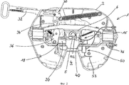
- фиг.2: вид снизу седельно-сцепного устройства;- figure 2: bottom view of the fifth wheel coupling device;
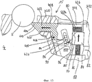
- фиг.3-9: увеличенные фрагменты вида снизу седельно-сцепного устройства по фиг.2 для пояснения различных положений запорного ригеля и стопорного элемента, а также для пояснения различных вариантов;- figure 3-9: enlarged fragments of a bottom view of the fifth wheel coupling of figure 2 to explain the different positions of the locking bolt and locking element, as well as to explain the various options;
- фиг.10: схематичный вид внизу седельно-сцепного устройства в другом варианте выполнения;- figure 10: a schematic bottom view of the fifth wheel coupling in another embodiment;
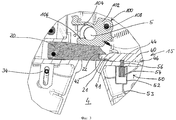
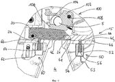
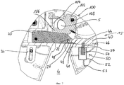
- фиг.11-14: предохранительное устройство в четырех различных положениях, в увеличенном масштабе.- 11-14: safety device in four different positions, on an enlarged scale.
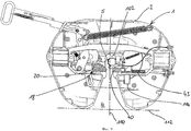
На фиг.1 показан тягач 10, содержащий седельно-сцепное устройство 1. Оно оснащено дополнительным предохранительным устройством 15, из которого на фиг.1 показано только первое исполнительное устройство 50, соединенное электрическим проводом 53а с устройством управления 70 в кабине 12.Figure 1 shows a
Исполнительное устройство 50 размещено на нижней стороне плиты 2 седельно-сцепного устройства 1 таким образом, что оно видно извне. Дополнительное оптическое устройство 58 может, например, мигать, сигнализируя о том, что предохранительное устройство 15 активировано. Эти меры должны с самого начала отпугнуть потенциальных угонщиков от отцепления полуприцепа (не показан) от тягача 10.
С помощью устройства управления 70 можно включать и выключать предохранительное устройство 15. Для этого может быть встроен соответствующий блок ввода, например кода.Using the
Устройство управления 70 может быть подключено также к устройству контроля 72, которое связано с запорной системой седельно-сцепного устройства электрическим проводом 53b (штрихпунктирная линия) и определяет состояние блокирования седельно-сцепного устройства. При этом речь может идти о противоугонном устройстве 74 с устройством 75а на запорном крюке и с индикаторным блоком и/или блоком управления 75b, который, например, образует устройство контроля 72 или встроен в него. Эта информация может использоваться для активирования или деактивирования предохранительного устройства 15 соответствующим предусмотренным образом посредством устройства управления 70.The
Такое устройство контроля может быть также противоугонным устройством или содержать противоугонное устройство, которое также воздействует на запорную систему седельно-сцепного устройства и при срабатывании блокирует ее. Также эта информация может использоваться для активирования или деактивирования предохранительного устройства 15.Such a control device can also be an anti-theft device or contain an anti-theft device, which also acts on the locking system of the fifth wheel coupling and, when triggered, blocks it. This information can also be used to activate or deactivate the
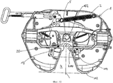
На фиг.2 представлен вид снизу седельно-сцепного устройства 1. Для ввода шкворня 5 плита 2 седельно-сцепного устройства имеет отверстие 4.Figure 2 presents a bottom view of the
Седельно-сцепное устройство 1 располагает запорной системой 18, содержащей запорное устройство 100 в виде запорного крюка 102 (фиг.3), запорный ригель 20 и рычажную систему 30 из тяги 32 и рычагов 34, 36. В своем запирающем положении запорный крюк 102 охватывает введенный шкворень 5. За счет закрывающей рамы 6 части запорной системы закрыты, так что взаимодействия отдельных компонентов запорной системы не видно. Положение отдельных компонентов соответствует положению на фиг.5.The
Чтобы переместить запорный ригель 20 в его запирающее положение, смещается тяга 32, причем это движение передается на него через рычаги 34, 36.To move the locking
По сравнению с запорным ригелем 20 стопорный элемент 40 выполнен в виде стопорного ригеля и в качестве составной части предохранительного устройства 15, принцип действия которого подробно поясняется в связи с фиг.3-9.Compared with the locking
За стопорным ригелем 40 расположен регулировочный винт 76, с помощью которого может регулироваться его исходное положение.Behind the locking
На фиг.3 представлен увеличенный подробный вид, показывающий взаимодействие запорного 20 и стопорного 40 ригелей.Figure 3 presents an enlarged detailed view showing the interaction of the locking 20 and locking 40 bolts.
Запорный крюк 102, образующий запорное устройство 100, поворачивается на оси 108 и имеет два колена 104, 106, которые охватывают шкворень 5 в запирающем положении. Чтобы фиксировать запорный крюк 102 в его запирающем положении, запорный ригель 20 смещен по стрелке перед запорным крюком, так что запорный ригель 20 оказывается в отверстии 4 для ввода. При этом колено 106 запорного крюка 102 прилегает к запорному ригелю, что предотвращает проворачивание запорного крюка 102.The
Напротив запорного ригеля 20 по другую сторону расположен стопорный ригель 40. В данном варианте выполнения запорный ригель 20 находится по одну сторону отверстия 4 для ввода, а стопорный ригель 40 - по другую. Стопорный ригель 40 имеет на своем переднем конце 41 соединительный элемент 42, входящий с зажатием в соответствующую выемку 22 на переднем конце 21 запорного ригеля 20. Посредством соединительного элемента 42 и выемки 22 создается разъемное соединение стопорного 40 и запорного 20 ригелей.Opposite the locking
Стопорный ригель 40 имеет на одной из своих обеих продольных сторон две выемки 44, 46. В его показанном здесь исходном положении в выемку 44 входит блокировочный штифт 56 первого исполнительного устройства 50. Этот блокировочный штифт 56 движется посредством актуатора 54. Последний расположен в корпусе 52. Актуатор 54 связан электрическим соединительным проводом 53 с устройством управления 70 (фиг.1).The locking
Исполнительное устройство 50 расположено таким образом, что блокировочный штифт 56 движется перпендикулярно направлению движения стопорного ригеля 40. В исходном положении стопорного ригеля 40 блокировочный штифт 56 входит в выемку 44, тем самым, блокируя его.The
Если запорный ригель 20 для отпирания санкционированным образом запорного крюка движется по стрелке влево (фиг.4), то запорный ригель 20 отделяется от стопорного ригеля 4, освобождая, тем самым, отверстие 4 для ввода. Запорный крюк может повернуться в отпирающее положение, в результате чего шкворень 5 может выйти.If the locking
Если же запорный ригель 20 приводится в действие несанкционированным образом, то исполнительное устройство 50 включается так, что блокировочный штифт 56 не входит в выемку 44. Блокировочный штифт 56 находится в отведенном положении и удерживается в нем. Стопорный ригель 40 движется, тем самым, свободно и захватывается запорным ригелем 20, так что последний тянет стопорный ригель 40 в запирающее положение. В этом положении передний конец с соединительным элементом 42 находится в отверстии 4 седельно-сцепного устройства (фиг.5). Только в этом положении запорный ригель 20 отделяется от стопорного ригеля 40.If the locking
Чтобы стопорный ригель 40 в результате смещения назад запорного ригеля 20 не мог снова сместиться обратно в свое исходное положение, блокировочный штифт 56 выдвинут, так что он входит в выемку 46. За счет этого стопорный ригель 40 фиксируется в своем запирающем положении. В этом положении запорный крюк может двигаться лишь ограниченно, причем он не отпускает шкворень. Это гарантирует то, что при несанкционированном приведении в действие запорного ригеля 20 не произойдет расцепки полуприцепа и тягача 10. Это обеспечивается находящимся в запирающем положении стопорным ригелем 40.So that the locking
Только за счет отпускания посредством устройства управления 70 блокировочный штифт 56 выходит из выемки 46, так что стопорный ригель 40 может быть снова смещен обратно в свое исходное положение на фиг.4.Only by releasing by means of the
На фиг.6 изображен другой вариант, в котором предусмотрено второе исполнительное устройство 60, в корпусе 62 которого расположен актуатор 64 с блокировочным штифтом 66. С его помощью обеспечивается блокировка запорного ригеля 20. Блокировочный штифт 66 входит в соответствующую выемку 24 запорного ригеля 20, когда тот находится в запирающем положении на фиг.6. Если происходит насильственное отпирание запорного ригеля 20, то он сначала фиксируется в своем положении. При насильственном отпирании блокировочный штифт 66 может быть поврежден, что обнаруживается соответствующим устройством. В этом случае соответствующий сигнал подается на устройство управления 70, которое в ответ на это оттягивает блокировочный штифт 66, так что стопорный ригель 40 освобождается и может свободно двигаться. За счет этого при смещении запорного ригеля 20, как это описано в связи с фиг.3-5, стопорный ригель 40 может переместиться в свое запирающее положение.FIG. 6 shows another embodiment in which a
На фиг.7 представлен особо предпочтительный вариант разъемного соединения стопорного 40 и запорного 20 ригелей. В соединительном элементе 42 стопорного ригеля 40 находится магнит 48, который незначительно выступает относительно соединительного элемента 42 и взаимодействует с запорным ригелем 20.7 shows a particularly preferred embodiment of the detachable connection of the locking 40 and locking 20 bolts. In the connecting
Другой вариант показан на фиг.8, причем запорный ригель 20 имеет фиксирующий носик 26, взаимодействующий с фиксирующим крюком 49 стопорного ригеля 40. Оба фиксирующих органа выполнены так, что при фиксации стопорного ригеля 40 запорный ригель 20 может отделяться от него. В то же время фиксирующие органы выполнены так, что возможен захват стопорного ригеля 40, если он освобожден, а запорный ригель несанкционированным образом движется в свое отпирающее положение.Another embodiment is shown in FIG. 8, wherein the locking
На фиг.9 представлен другой вариант, в котором стопорный ригель 40 приводится в действие пружиной 43. Запорный ригель 20 находится в своем отпирающем положении, так что запорный крюк 102 может двигаться в свое отпирающее положение. За счет того, что стопорный ригель 40 смещается пружиной 43, которая воздействует на его обратную сторону, в отверстие 4, запорный крюк 102 блокируется, в результате чего он не может быть полностью отперт.Fig. 9 shows another embodiment in which the
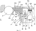
На фиг.10 изображен другой вариант, в котором стопорный ригель 400 расположен на расстоянии от запорной системы 18 седельно-сцепного устройства 1. Отверстие 4 проходит от внешней ограничительной линии 112 до запорной системы 18, причем линия 114 обозначает середину. Стопорный ригель 400 находится в направлении ввода в задней половине между средней линией 114 и запорной системой 18. Стопорный ригель 400 находится сбоку отверстия 4 с возможностью перемещения, так что он может перемещаться также перпендикулярно продольной оси 110 отверстия 4.Figure 10 shows another embodiment in which the
Стопорный ригель 400 (фиг.11) имеет выступ, так что образуется опорная поверхность 106, прилегающая к боковой стенке 424 плиты 2 седельно-сцепного устройства.The locking bolt 400 (FIG. 11) has a protrusion, so that a supporting
Стопорный ригель 400 направляется на своей продольной стороне 408 направляющим ребром 420, а на противоположной стороне 409 - ребром 425 боковой стенки 424 и находится в камере 500, имеющей сбоку дополнительную меньшую камеру 502, в которой расположена вторая пружина 80.The
Эта пружина 80 опирается на направляющее ребро 422 и давит на стопорный ригель 400 в положение на фиг.11.This
Стопорный ригель 400 содержит собачку 90, снабженную на своей верхней стороне пальцем 98, установленным в седельно-сцепном устройстве с возможностью вращения. Стопорный ригель 400 содержит палец 94, входящий в паз 92 собачки 90, так что последняя может перемещаться в своем продольном направлении.The
Передний конец собачки 90 имеет острие 96, воздействующее на носик 85 блокировочного элемента 84 блокировочного устройства 82. Блокировочный элемент 84 расположен также подвижно. Направление его движения перпендикулярно направлению движения стопорного ригеля 400.The front end of the
Блокировочный элемент 84 содержит пружину 86, которая движет его в направлении стопорного ригеля 400. За счет собачки блокировочный элемент 84 удерживается в своем отпертом положении, так что стопорный ригель 400 может перемещаться против усилия пружины 80.The locking
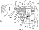
На фиг.12 представлен процесс ввода шкворня 5. Он воздействует на вводной скос 410 острия 404 стопорного ригеля 400 и перемещает последний по стрелке, т.е. внутрь камеры 500, против усилия пружины 80. При этом собачка 90 приводится в действие пальцем 94 и поворачивается вокруг пальца 98, в результате чего острие 96 собачки отделяется от носика 85 блокировочного элемента 84. Вследствие этого блокировочный элемент 84 прижимается пружиной 86 к стопорному ригелю 400.12 shows the input process of the
На фиг.12 блокировочный элемент 84 своим скосом 87 упирается в угол стопорного ригеля 400. Как только шкворень 5 будет полностью введен, пружина 86 вдавливает стопорный ригель 400 в отверстие 4 для ввода, в результате чего он занимает свое запирающее положение. За счет этого стопорный ригель 400 освобождает блокировочный элемент 84, так что тот входит в свободное пространство 504 за стопорным ригелем 400, пока не упрется в выступ 426 направляющего ребра 422.12, the locking
Движение стопорного ригеля 400 против стрелки на фиг.13 больше невозможно, поскольку между ребром 422 и ним расположен блокировочный элемент 84. Это обеспечивает защиту, которая препятствует повторному выходу шкворня 5.The movement of the
Если шкворень должен быть освобожден, то блокировочный элемент 84 смещается посредством актуатора 88 по стрелке против усилия пружины 86 (фиг.14), так что стопорный ригель 400 снова получает возможность свободного движения. При выдвигании шкворня 5 он движет стопорный ригель 400 по стрелке против усилия пружины 80, причем в то же время собачка 90 поворачивается таким образом, что ее острие 96 входит в носик 85 блокировочного элемента 84, блокируя его в его исходном положении.If the king pin is to be released, then the locking
Claims (40)
Applications Claiming Priority (3)
| Application Number | Priority Date | Filing Date | Title |
|---|---|---|---|
| DE102008000799.4 | 2008-03-20 | ||
| DE102008000799A DE102008000799A1 (en) | 2008-03-20 | 2008-03-20 | fifth wheel |
| PCT/EP2009/053254 WO2009115576A1 (en) | 2008-03-20 | 2009-03-19 | Fifth-wheel coupling |
Publications (2)
| Publication Number | Publication Date |
|---|---|
| RU2010142927A RU2010142927A (en) | 2012-04-27 |
| RU2503573C2 true RU2503573C2 (en) | 2014-01-10 |
Family
ID=40637043
Family Applications (1)
| Application Number | Title | Priority Date | Filing Date |
|---|---|---|---|
| RU2010142927/11A RU2503573C2 (en) | 2008-03-20 | 2009-03-19 | Truck coupler |
Country Status (11)
| Country | Link |
|---|---|
| US (1) | US8616575B2 (en) |
| EP (1) | EP2257460B9 (en) |
| CN (1) | CN102046453B (en) |
| BR (1) | BRPI0909129B1 (en) |
| CA (1) | CA2718874C (en) |
| DE (1) | DE102008000799A1 (en) |
| ES (1) | ES2451512T3 (en) |
| MX (1) | MX2010010206A (en) |
| RU (1) | RU2503573C2 (en) |
| WO (1) | WO2009115576A1 (en) |
| ZA (1) | ZA201006527B (en) |
Cited By (1)
| Publication number | Priority date | Publication date | Assignee | Title |
|---|---|---|---|---|
| RU2730809C1 (en) * | 2018-08-01 | 2020-08-26 | Йост-Верке Дойчланд Гмбх | Fifth-wheel coupling connecting plate |
Families Citing this family (9)
| Publication number | Priority date | Publication date | Assignee | Title |
|---|---|---|---|---|
| US9126464B2 (en) * | 2012-06-12 | 2015-09-08 | Saf-Holland, Inc. | Fifth wheel assembly with automatic lockouts |
| DE102012214413B4 (en) | 2012-08-14 | 2016-08-11 | Jost-Werke Gmbh | FIFTH WHEEL |
| BR102013028578A2 (en) * | 2013-11-06 | 2016-02-02 | Naira Hosana Silvestrini Maschio | fifth wheel handle lever remote lock |
| CN103754279B (en) * | 2014-02-12 | 2017-02-22 | 中国重汽集团济南动力有限公司 | Anti-locking saddle locking mechanism |
| CN106347464B (en) * | 2016-10-17 | 2018-08-03 | 湖北华舟重工应急装备股份有限公司 | Without bridge semi-trailer frame tail portion cross-connecting apparatus |
| US10807564B2 (en) * | 2019-03-18 | 2020-10-20 | Honda Motor Co., Ltd. | Seat haptic system and method of deterring vehicle theft |
| US20210125433A1 (en) * | 2019-10-23 | 2021-04-29 | Brandon Gonzalez | Safety system for coupling truck and trailer |
| DE102020112815B4 (en) | 2020-05-12 | 2025-10-16 | Saf-Holland Gmbh | Fifth wheel coupling with safety device |
| KR20240002020A (en) * | 2022-06-28 | 2024-01-04 | 현대자동차주식회사 | Container swapable vehicle and its control meth |
Citations (3)
| Publication number | Priority date | Publication date | Assignee | Title |
|---|---|---|---|---|
| US3876239A (en) * | 1974-08-05 | 1975-04-08 | Southwest Wheel & Mfg | Fifth wheel safety device |
| SU1384460A1 (en) * | 1986-10-10 | 1988-03-30 | Специальное конструкторское бюро "СКБ-Мосстрой" | Vehicle fifth-wheel traction coupling |
| US20040145150A1 (en) * | 2001-11-19 | 2004-07-29 | Yeakel Willard Supplee | Remote locking fifth wheel |
Family Cites Families (10)
| Publication number | Priority date | Publication date | Assignee | Title |
|---|---|---|---|---|
| GB1234962A (en) * | 1968-06-12 | 1971-06-09 | John Greenwood Slaven | Improvements in vehicle couplers |
| GB2281057A (en) * | 1993-04-28 | 1995-02-22 | Wolverhampton Enterprise Limit | Trailer security system |
| US5472223A (en) | 1993-11-30 | 1995-12-05 | Amsted Industries Incorporated | Air operated fifth wheel |
| DE19516101A1 (en) | 1995-05-05 | 1996-11-07 | Diehl Remscheid Gmbh & Co | Anti-theft device for coupled semi-trailer |
| US5876055A (en) * | 1998-03-04 | 1999-03-02 | Fontaine; John P. K. | Automatic tolerance reducing greaseless fifth wheel using a wedge and jaw locking system that eliminates squirting |
| GB2343433B (en) * | 1999-10-01 | 2000-09-27 | Vbg Limited | Fifth wheel coupling |
| AU2002365976A1 (en) | 2001-11-19 | 2003-06-10 | Volvo Trucks North America Inc. | Remote locking fifth wheel |
| US6873909B2 (en) | 2001-11-19 | 2005-03-29 | Volvo Trucks North America, Inc. | System for preventing unauthorized trailer uncoupling |
| DE10241904B9 (en) * | 2002-09-06 | 2008-12-18 | Jost-Werke Gmbh | Sensor for kingpin |
| DE10341019B4 (en) | 2003-09-03 | 2013-01-31 | Saf-Holland Verkehrstechnik Gmbh | Fifth wheel with anti-theft device |
-
2008
- 2008-03-20 DE DE102008000799A patent/DE102008000799A1/en not_active Withdrawn
-
2009
- 2009-03-19 RU RU2010142927/11A patent/RU2503573C2/en not_active IP Right Cessation
- 2009-03-19 CN CN200980118145.9A patent/CN102046453B/en not_active Expired - Fee Related
- 2009-03-19 CA CA2718874A patent/CA2718874C/en not_active Expired - Fee Related
- 2009-03-19 WO PCT/EP2009/053254 patent/WO2009115576A1/en not_active Ceased
- 2009-03-19 US US12/933,262 patent/US8616575B2/en not_active Expired - Fee Related
- 2009-03-19 MX MX2010010206A patent/MX2010010206A/en active IP Right Grant
- 2009-03-19 ES ES09722694.8T patent/ES2451512T3/en active Active
- 2009-03-19 BR BRPI0909129 patent/BRPI0909129B1/en active IP Right Grant
- 2009-03-19 EP EP09722694.8A patent/EP2257460B9/en active Active
-
2010
- 2010-09-13 ZA ZA2010/06527A patent/ZA201006527B/en unknown
Patent Citations (3)
| Publication number | Priority date | Publication date | Assignee | Title |
|---|---|---|---|---|
| US3876239A (en) * | 1974-08-05 | 1975-04-08 | Southwest Wheel & Mfg | Fifth wheel safety device |
| SU1384460A1 (en) * | 1986-10-10 | 1988-03-30 | Специальное конструкторское бюро "СКБ-Мосстрой" | Vehicle fifth-wheel traction coupling |
| US20040145150A1 (en) * | 2001-11-19 | 2004-07-29 | Yeakel Willard Supplee | Remote locking fifth wheel |
Cited By (1)
| Publication number | Priority date | Publication date | Assignee | Title |
|---|---|---|---|---|
| RU2730809C1 (en) * | 2018-08-01 | 2020-08-26 | Йост-Верке Дойчланд Гмбх | Fifth-wheel coupling connecting plate |
Also Published As
| Publication number | Publication date |
|---|---|
| CA2718874C (en) | 2016-08-30 |
| EP2257460B1 (en) | 2014-02-26 |
| EP2257460A1 (en) | 2010-12-08 |
| RU2010142927A (en) | 2012-04-27 |
| CA2718874A1 (en) | 2009-09-24 |
| BRPI0909129A2 (en) | 2015-11-24 |
| ES2451512T3 (en) | 2014-03-27 |
| CN102046453A (en) | 2011-05-04 |
| BRPI0909129B1 (en) | 2019-11-26 |
| ZA201006527B (en) | 2011-05-25 |
| US20110025020A1 (en) | 2011-02-03 |
| DE102008000799A1 (en) | 2009-10-01 |
| MX2010010206A (en) | 2010-10-05 |
| EP2257460B9 (en) | 2014-09-10 |
| US8616575B2 (en) | 2013-12-31 |
| CN102046453B (en) | 2014-04-02 |
| WO2009115576A1 (en) | 2009-09-24 |
Similar Documents
| Publication | Publication Date | Title |
|---|---|---|
| RU2503573C2 (en) | Truck coupler | |
| RU2467896C2 (en) | Antitheft device for automotive coupling device | |
| CN101395048A (en) | System for automatically actuating a parking brake on a vehicle | |
| US20010050509A1 (en) | Trailer locking device | |
| US4838570A (en) | Method, control system and equipment to prevent the theft of an articulated vehicle and/or a trailer to be connected with a drawing vehicle | |
| US8371600B2 (en) | Fifth wheel with anti-theft protection device | |
| NL1014376C1 (en) | Locking device for protecting the hydraulic circuit, called hydralock, usually for trucks. | |
| EP4286257B1 (en) | Tractor-trailer combination with emergency locking kingpin | |
| EP0152277A1 (en) | Goods vehicle locking arrangement | |
| EP1322506B1 (en) | Locking device for a semitrailer | |
| EP1409271A1 (en) | Trailer locking device | |
| CA2548801A1 (en) | Trailer anti-theft device | |
| SK85597A3 (en) | Anti-theft mechanical safety device for a vehicle |
Legal Events
| Date | Code | Title | Description |
|---|---|---|---|
| MM4A | The patent is invalid due to non-payment of fees |
Effective date: 20200320 |