RU2503125C2 - Control of power consumption of receiving module - Google Patents
Control of power consumption of receiving module Download PDFInfo
- Publication number
- RU2503125C2 RU2503125C2 RU2010136978/07A RU2010136978A RU2503125C2 RU 2503125 C2 RU2503125 C2 RU 2503125C2 RU 2010136978/07 A RU2010136978/07 A RU 2010136978/07A RU 2010136978 A RU2010136978 A RU 2010136978A RU 2503125 C2 RU2503125 C2 RU 2503125C2
- Authority
- RU
- Russia
- Prior art keywords
- receiving module
- power consumption
- module
- receiving
- wireless
- Prior art date
Links
Images


Classifications
-
- H—ELECTRICITY
- H04—ELECTRIC COMMUNICATION TECHNIQUE
- H04W—WIRELESS COMMUNICATION NETWORKS
- H04W52/00—Power management, e.g. TPC [Transmission Power Control], power saving or power classes
- H04W52/02—Power saving arrangements
- H04W52/0209—Power saving arrangements in terminal devices
- H04W52/0261—Power saving arrangements in terminal devices managing power supply demand, e.g. depending on battery level
- H04W52/0274—Power saving arrangements in terminal devices managing power supply demand, e.g. depending on battery level by switching on or off the equipment or parts thereof
- H04W52/028—Power saving arrangements in terminal devices managing power supply demand, e.g. depending on battery level by switching on or off the equipment or parts thereof switching on or off only a part of the equipment circuit blocks
-
- Y—GENERAL TAGGING OF NEW TECHNOLOGICAL DEVELOPMENTS; GENERAL TAGGING OF CROSS-SECTIONAL TECHNOLOGIES SPANNING OVER SEVERAL SECTIONS OF THE IPC; TECHNICAL SUBJECTS COVERED BY FORMER USPC CROSS-REFERENCE ART COLLECTIONS [XRACs] AND DIGESTS
- Y02—TECHNOLOGIES OR APPLICATIONS FOR MITIGATION OR ADAPTATION AGAINST CLIMATE CHANGE
- Y02D—CLIMATE CHANGE MITIGATION TECHNOLOGIES IN INFORMATION AND COMMUNICATION TECHNOLOGIES [ICT], I.E. INFORMATION AND COMMUNICATION TECHNOLOGIES AIMING AT THE REDUCTION OF THEIR OWN ENERGY USE
- Y02D30/00—Reducing energy consumption in communication networks
- Y02D30/70—Reducing energy consumption in communication networks in wireless communication networks
Abstract
Description
ОБЛАСТЬ ТЕХНИКИ, К КОТОРОЙ ОТНОСИТСЯ ИЗОБРЕТЕНИЕFIELD OF THE INVENTION
Изобретение относится к устройству для управления энергопотреблением принимающего модуля. Изобретение так же относится к дополнительному устройству, системе и способу.The invention relates to a device for power management of a receiving module. The invention also relates to an additional device, system and method.
Примерами таких принимающих модулей являются модули для приема беспроводных или небеспроводных сигналов управления функционированием для управления приборами, такими как лампы и другие приборы и изделия, в ответ на прием этих беспроводных или небеспроводных сигналов управления функционированием.Examples of such receiving modules are modules for receiving wireless or non-wireless operation control signals for controlling devices, such as lamps and other devices and products, in response to receiving these wireless or non-wireless operation control signals.
ПРЕДШЕСТВУЮЩИЙ УРОВЕНЬ ТЕХНИКИBACKGROUND OF THE INVENTION
US 2006/0154598 раскрывает способ конфигурирования и эксплуатации радиосистемы, использующей радиостандарт ZigBee. Способ дает возможность группе радиоустройств, которые логически соединены с другим радиоустройством, реагировать на сообщение с малым временем ожидания. Способ содержит группу идентификаторов, сформированных и выпущенных логически соединенными устройствами, подробности которых предоставлены в заранее установленной связующей таблице. Во время работы, радиосообщение от устройства, которое логически соединено с другим, принимается средством координирования устройства, которое затем транслирует сообщение со сформированным идентификатором группы. Только те устройства, которые предварительно приняли согласующий группу идентификатор, реагируют на сообщение трансляции. Так как трансляции не требуют подтверждения, достигается быстрая реакция системы.US 2006/0154598 discloses a method for configuring and operating a radio system using a ZigBee radio standard. The method enables a group of radio devices that are logically connected to another radio device to respond to a message with a short waiting time. The method comprises a group of identifiers generated and issued by logically connected devices, the details of which are provided in a predefined link table. During operation, a radio message from a device that is logically connected to another is received by the device coordinator, which then transmits a message with the generated group identifier. Only those devices that have previously received the identifier matching group respond to the broadcast message. Since the broadcasts do not require confirmation, a quick response of the system is achieved.
US 5.081.402 раскрывает систему управления и беспроводной передачи данных с низким энергопотреблением, которая используется для того, чтобы автоматически координировать экран посредством использования передаваемого сигнала команд. Система содержит в себе приемник/модуль обнаружения, который выборочно приводится в действие только на определенные интервалы времени, тем самым позволяя, главным образом, принять все ранее переданные сигналы, при этом снижая энергию, потребляемую модулем обнаружения во время периодов, в которых сигналы отсутствуют.US 5.081.402 discloses a low-power control and wireless data transmission system that is used to automatically coordinate a screen by using a transmitted command signal. The system contains a receiver / detection module, which is selectively activated only for certain time intervals, thereby allowing, mainly, to receive all previously transmitted signals, while reducing the energy consumed by the detection module during periods in which there are no signals.
ЗАДАЧА И КРАТКОЕ ОПИСАНИЕ СУЩНОСТИ ИЗОБРЕТЕНИЯSUMMARY AND SUMMARY OF THE INVENTION
Задачей изобретения является предоставить устройство для управления энергопотреблением принимающего модуля.The objective of the invention is to provide a device for energy management of the receiving module.
Дополнительными задачами являются предоставить дополнительное устройство, систему и способ.Additional tasks are to provide an additional device, system and method.
В соответствии с первым аспектом, предоставлено устройство для управления энергопотреблением принимающего модуля, который выполнен с возможностью управлять прибором, при этом принимающий модуль является беспроводным или небеспроводным принимающим модулем для управления прибором, в ответ на прием беспроводного или не беспроводного сигнала управления функционированием от передающего модуля, при этом прибор содержит изделие, которое удаленно управляется посредством комбинации передающего модуля и принимающего модуля, причем устройство содержит модуль управления, который в ответ на определение состояния прибора управляет энергопотреблением принимающего модуля для снижения его среднего энергопотребления, при этом устройство дополнительно содержит приемник, для приема сигнала управления функционированием, и устройство выполнено с возможностью выключать принимающий модуль, когда прибор включен или выключен, или находится в другом состоянии, и обратно включать принимающий модуль, в качестве реакции на прием сигнала управления функционированием.In accordance with a first aspect, an apparatus is provided for controlling power consumption of a receiving module, which is configured to control a device, the receiving module being a wireless or non-wireless receiving module for controlling the device, in response to receiving a wireless or non-wireless operation control signal from the transmitting module, wherein the device contains a product that is remotely controlled by a combination of a transmitting module and a receiving module, moreover, your device contains a control module that, in response to determining the status of the device, controls the power consumption of the receiving module to reduce its average power consumption, while the device further comprises a receiver for receiving the operation control signal, and the device is configured to turn off the receiving module when the device is on or off, or is in a different state, and turn the receiving module back on, in response to receiving the operation control signal.
Состоянием может быть, например, текущее состояние прибора, указывающее, например, что прибор включен или выключен. Модуль управления управляет энергопотреблением принимающего модуля в зависимости от обнаруженного состояния этого прибора для снижения среднего энергопотребления принимающего модуля. Например, когда прибор включен (выключен) и когда модуль управления знает, что в течение предопределенного интервала времени нет необходимости выключать (включать) прибор, принимающий модуль может быть выключен на этот предопределенный интервал времени. Это снижает среднее энергопотребление принимающего модуля.The state may be, for example, the current state of the device, indicating, for example, that the device is on or off. The control module controls the power consumption of the receiving module depending on the detected state of this device to reduce the average power consumption of the receiving module. For example, when the device is turned on (off) and when the control module knows that during a predetermined time interval there is no need to turn off (turn on) the device, the receiving module can be turned off for this predetermined time interval. This reduces the average power consumption of the receiving module.
Вместо двух состояний, прибор может иметь три и более состояния. Не исключаются состояния, отличные от текущих состояний и включенных/выключенных состояний. Для снижения среднего энергопотребления принимающего модуля вместо информации о предопределенном интервале времени может использоваться другая информация.Instead of two states, the device can have three or more states. States other than current states and on / off states are not excluded. To reduce the average power consumption of the receiving module, other information may be used instead of information about a predetermined time interval.
В одном варианте осуществления, устройство выполнено с возможностью управлять энергопотреблением дополнительным принимающим модулем, который выполнен с возможностью управлять дополнительным прибором, в ответ на обнаружение состояния дополнительного прибора, при этом модуль управления выполнен с возможностью управлять энергопотреблением дополнительного принимающего модуля для снижения его среднего энергопотребления. Дополнительно, повышается общая эффективность, если одно устройство управляет энергопотреблением двух или более принимающих модулей, и, в расчете на единицу устройства, может быть снижено большее среднее энергопотребление.In one embodiment, the device is configured to control the power consumption of the additional receiving module, which is configured to control the additional device, in response to detecting the state of the additional device, while the control module is configured to control the power consumption of the additional receiving module to reduce its average power consumption. Additionally, overall efficiency is improved if one device controls the power consumption of two or more receiving modules, and, per unit of the device, a higher average power consumption can be reduced.
В дополнительном варианте осуществления, принимающий модуль образует часть привода лампы, и/или лампу содержит прибор. Модуль обнаружения для обнаружения состояния прибора может содержать, или может быть связан с, например, фоторезистором или фотодиодом или солнечным элементом и может обнаруживать, что лампа, например, включена или выключена или находится в режиме подсветки. Такой модуль обнаружения может формировать часть устройства.In a further embodiment, the receiving module forms part of the lamp drive, and / or the lamp comprises a device. The detection module for detecting the status of the device may contain, or may be associated with, for example, a photoresistor or a photodiode or a solar cell, and may detect that the lamp, for example, is turned on or off or is in backlight mode. Such a detection module may form part of the device.
В другом варианте осуществления, модуль управления осуществляет связь через беспроводной или небеспроводной интерфейс для управления энергопотреблением принимающего модуля беспроводным или небеспроводным образом, и/или модуль управления осуществляет связь через физический и/или логический интерфейс для управления энергопотреблением принимающего модуля физически и/или логически. Модуль управления может управлять, например, энергопотреблением принимающего модуля беспроводным образом посредством беспроводного сигнал управления питанием, и в этом случае принимающий модуль должен содержать средство для приема такого беспроводного сигнала управления питанием. Беспроводной сигнал управления питанием и беспроводной сигнал управления функционированием может быть определен посредством либо того же самого, либо отличного стандарта. Модуль управления может управлять, например, энергопотреблением принимающего модуля небеспроводным образом посредством небеспроводного сигнала управления питанием, в таком случае принимающий модуль должен содержать средство для приема такого небеспроводного сигнала управления питанием. Небеспроводной сигнал управления питанием и небеспроводной сигнал управления функционированием могут быть определены посредством либо того же самого, либо отличного стандарта. Как сигнал управления питанием, так и сигнал управления функционированием могут быть беспроводными или небеспроводными сигналами, или один из них может быть беспроводным сигналом, при этом другой является небеспроводным сигналом. Модуль управления может содержать, например, физический интерфейс для физического управления энергопотреблением принимающего модуля, например, путем управления, протекающим электрическим током, и/или подаваемым напряжением к принимающему модулю. Модуль управления может содержать, например, логический интерфейс, для управления энергопотреблением принимающего модуля логически, например, путем отправки принимающему модулю команды управления питанием.In another embodiment, the control module communicates via a wireless or non-wireless interface to control the power consumption of the receiving module wirelessly or non-wirelessly, and / or the control module communicates through the physical and / or logical interface to control the power consumption of the receiving module physically and / or logically. The control module may control, for example, the power consumption of the receiving module wirelessly by means of a wireless power control signal, in which case the receiving module must include means for receiving such a wireless power control signal. The wireless power control signal and the wireless operation control signal can be determined by either the same or a different standard. The control module may control, for example, the power consumption of the receiving module in a non-wireless manner through a non-wireless power control signal, in which case the receiving module should include means for receiving such a non-wireless power control signal. The non-wireless power control signal and the non-wireless operation control signal can be determined by either the same or a different standard. Both the power control signal and the operation control signal may be wireless or non-wireless signals, or one of them may be a wireless signal, the other being a non-wireless signal. The control module may comprise, for example, a physical interface for physically controlling the power consumption of the receiving module, for example, by controlling the flow of electric current and / or the voltage supplied to the receiving module. The control module may comprise, for example, a logical interface for logically controlling the power consumption of the receiving module, for example, by sending a power management command to the receiving module.
И, кроме того, в дополнительном варианте осуществления, устройство дополнительно содержит регистратор для отслеживания энергопотребления, и/или протекающего электрического тока, и/или подаваемого напряжения к принимающему модулю и/или прибору. Таким образом, устройство может получать текущую информацию о принимающем модуле и/или о приборе.And, in addition, in a further embodiment, the device further comprises a recorder for monitoring power consumption and / or flowing electric current and / or voltage supplied to the receiving module and / or device. Thus, the device can receive current information about the receiving module and / or the device.
Принимающий модуль является беспроводным или небеспроводным принимающим модулем для управления прибором в ответ на прием беспроводного или небеспроводного сигнала управления функционированием от передающего модуля. Принимающий модуль может управлять прибором в соответствии с любым беспроводным или небеспроводным стандартом.The receiving module is a wireless or non-wireless receiving module for controlling the device in response to receiving a wireless or non-wireless operation control signal from the transmitting module. The receiving module can control the device in accordance with any wireless or non-wireless standard.
Устройство дополнительно содержит приемник для приема сигнала управления функционированием. Таким образом, устройство может воспринимать сигнал управления функционированием и может получать дополнительную информацию о принимающем модуле и/или о приборе.The device further comprises a receiver for receiving a function control signal. Thus, the device can perceive the operation control signal and can receive additional information about the receiving module and / or the device.
В дополнительном варианте осуществления, устройство так же содержит модуль обнаружения, для обнаружения состояния прибора, в ответ на прием сигнала управления функционированием. В этом случае, состояние прибора является дополнительным состоянием, в которое прибор должен быть вскоре приведен.In a further embodiment, the device also comprises a detection module for detecting a state of the device in response to receiving a function control signal. In this case, the state of the device is an additional state in which the device should be brought back soon.
В дополнительном варианте осуществления, устройство так же содержит передатчик для передачи, и/или ретрансляции сигнала управления функционированием к принимающему модулю. В соответствии с этой опцией, устройство переадресует сигнал управления функционированием принимающему модулю. Это может быть сделано сразу после приема, или после окончания или прекращения интервала времени, или после того, как оно убедится, что на принимающий модуль подается питание и/или он способен принять этот сигнал управления функционированием. Передача сигнала управления функционированием может содержать передачу сигнала, единичную ретрансляцию и/или повторную ретрансляцию и т.д.In a further embodiment, the device also comprises a transmitter for transmitting and / or relaying a function control signal to the receiving module. According to this option, the device forwards the operation control signal to the receiving module. This can be done immediately after reception, or after the end or termination of the time interval, or after it is convinced that the receiving module is supplied with power and / or it is capable of receiving this operation control signal. The transmission of the operation control signal may comprise signal transmission, a single relay and / or retransmission, etc.
И, кроме того, в дополнительном варианте осуществления, устройство содержит модуль преобразования для преобразования сигнала управления функционированием в преобразованный сигнал и устройство содержит передатчик для передачи и/или ретрансляции преобразованного сигнала принимающему модулю. В соответствии с этой опцией, устройство преобразует сигнал управления функционированием и затем передает преобразованный сигнал принимающему модулю. Это может быть сделано сразу после преобразования, или после окончания или прекращения интервала времени, или после того, как оно убедится, что на принимающий модуль подается питание и/или он способен принять этот преобразованный сигнал. Передача преобразованного сигнала может содержать единичную передачу, единичную ретрансляцию и/или повторную ретрансляцию и т.д.And, in addition, in a further embodiment, the device comprises a conversion module for converting the operation control signal into a converted signal, and the device comprises a transmitter for transmitting and / or relaying the converted signal to the receiving module. According to this option, the device converts the operation control signal and then transmits the converted signal to the receiving module. This can be done immediately after the conversion, or after the end or termination of the time interval, or after it is convinced that the receiving module is supplied with power and / or it is able to receive this converted signal. Transmission of the converted signal may comprise a single transmission, a single relay and / or retransmission, etc.
В другом варианте осуществления, модуль управления связывается через передатчик для управления энергопотреблением принимающего модуля посредством преобразованного сигнала. В этой высокоэффективной ситуации, преобразованный сигнал соответствует сигналу управления питанием, и модуль управления управляет энергопотреблением принимающего модуля посредством передачи принимающему модулю преобразованного сигнала.In another embodiment, the control module communicates through a transmitter to control the power consumption of the receiving module through the converted signal. In this highly efficient situation, the converted signal corresponds to a power control signal, and the control module controls the power consumption of the receiving module by transmitting the converted signal to the receiving module.
В другом варианте осуществления, устройство так же содержит память для хранения сигнала управления функционированием и/или преобразованного сигнала.In another embodiment, the device also comprises a memory for storing the operation control signal and / or the converted signal.
И, кроме того, в другом варианте осуществления, устройство дополнительно содержит процессор, который в ответ на анализ трафика, обмен которым осуществляется через принимающий модуль, и/или анализ энергопотребления, и/или протекающего электрического тока, и/или подаваемого напряжения к принимающему модулю и/или прибору, формирует статистику и/или сообщение, и/или приспосабливает поведение устройства. Устройство может быть объединено, или дополнительно содержать память для хранения такой статистики, сообщений и/или поведения.And, in addition, in another embodiment, the device further comprises a processor, which in response to the analysis of traffic exchanged through the receiving module and / or the analysis of energy consumption and / or the flowing electric current and / or voltage supplied to the receiving module and / or the instrument, generates statistics and / or message, and / or adapts the behavior of the device. The device may be combined, or further comprise a memory for storing such statistics, messages and / or behavior.
В соответствии со вторым аспектом, дополнительно предоставлено устройство для управления энергопотреблением устройства, как определено выше, при этом дополнительное устройство содержит дополнительный модуль управления, который в ответ на обнаружение состояния устройства и/или принимающего модуля и/или прибора управляет энергопотреблением устройства для снижения его среднего энергопотребления. Таким образом, создается иерархическая система. Прибор и принимающий модуль могут находиться на самом нижнем уровне, устройство может находиться на среднем уровне, а дополнительное устройство может находиться на наивысшем уровне. В качестве альтернативы, прибор может находиться на самом нижнем уровне, принимающий модуль может находиться на более низком среднем уровне, устройство может находиться на более высоком среднем уровне, а дополнительное устройство может находиться на наивысшем уровне. Не должны исключаться дополнительные и другие уровни.In accordance with a second aspect, an apparatus for controlling energy consumption of a device as defined above is further provided, wherein the additional device comprises an additional control module that, in response to detecting a state of the device and / or the receiving module and / or device, controls the energy consumption of the device to reduce its average power consumption. Thus, a hierarchical system is created. The device and the receiving module can be at the lowest level, the device can be at the middle level, and the additional device can be at the highest level. Alternatively, the device may be at the lowest level, the receiving module may be at a lower average level, the device may be at a higher average level, and the accessory device may be at the highest level. Additional and other levels should not be excluded.
В одном варианте осуществления, дополнительное устройство так же содержит приемник, для приема сигнала управления функционирования, при этом дополнительное устройство выполнено с возможностью выключать устройство, когда прибор включен или выключен или находится в другом состоянии, и/или когда принимающий модуль включен или выключен или находится в другом состоянии, и/или когда устройство включено или находится в другом состоянии и для того, чтобы обратно включить устройство, в качестве реакции на прием сигнала управления функционированием.In one embodiment, the accessory device also comprises a receiver for receiving an operation control signal, wherein the accessory device is configured to turn off the device when the device is turned on or off or is in a different state, and / or when the receiving module is turned on or off or is in a different state, and / or when the device is turned on or in a different state and in order to turn the device back on, in response to receiving a control signal Niemi.
В соответствии с третьим аспектом, предоставлена система, содержащая, по меньшей мере, одно устройство, как определено выше, при этом система дополнительно содержит, по меньшей мере, одно, дополнительное устройство, как определено выше, и/или, по меньшей мере, один принимающий модуль и/или, по меньшей мере, один прибор. Такой системой, например, может быть здание, содержащее дополнительное устройство из расчета на этаж, для управления этажом и содержащее, из расчета на этаж, устройство из расчета на помещение, для управления помещением.In accordance with a third aspect, a system is provided comprising at least one device as defined above, the system further comprising at least one additional device as defined above and / or at least one a receiving module and / or at least one device. Such a system, for example, can be a building containing an additional device per floor for controlling the floor and containing, per floor, a device per room for controlling the room.
В соответствии с четвертым аспектом, предоставлен способ для управления энергопотреблением принимающего модуля, который выполнен с возможностью управления прибором, при этом принимающий модуль является беспроводным или небеспроводным принимающим модулем для управления прибором, в ответ на прием беспроводного или не беспроводного сигнала управления функционированием от передающего модуля, при этом прибор содержит изделие, которое удаленно управляется посредством комбинации передающего модуля и принимающего модуля, при этом способ содержит этап управления, в ответ на обнаружение статуса прибора, энергопотреблением принимающего модуля для снижения его среднего энергопотребления, при этом способ дополнительно содержит этап приема сигнала управления функционированием, и при этом способ дополнительно содержит этапы выключения принимающего модуля, когда прибор включен или выключен, или находится в другом состоянии, и обратного включения принимающего модуля, в качестве реакции на прием сигнала управления функционированием.According to a fourth aspect, there is provided a method for controlling power consumption of a receiving module that is configured to control a device, the receiving module being a wireless or non-wireless receiving module for controlling the device, in response to receiving a wireless or non-wireless operation control signal from the transmitting module, wherein the device comprises an article that is remotely controlled by a combination of a transmitting module and a receiving module, the method comprises a control step, in response to detecting the status of the device, by the power consumption of the receiving module to reduce its average power consumption, the method further comprising the step of receiving the operation control signal, and the method further comprises the steps of turning off the receiving module when the device is on or off, or is in another state, and reverse the receiving module, in response to the reception of the operation control signal.
Изобретение может быть основано на распознавании того, что должна быть введена (большая) иерархия. Основная идея могла бы состоять в том, что устройство должно быть предоставлено с модулем управления, который, в ответ на обнаружение состояния прибора, управляет энергопотреблением принимающего модуля, который управляет прибором для снижения среднего энергопотребления принимающего модуля.The invention may be based on the recognition that a (large) hierarchy should be introduced. The main idea could be that the device should be provided with a control module that, in response to detecting the status of the device, controls the power consumption of the receiving module, which controls the device to reduce the average power consumption of the receiving module.
В соответствии с изобретением, устройство имеет преимущество, которое заключается в том, что может быть снижено энергопотребление.According to the invention, the device has the advantage that energy consumption can be reduced.
Эти и другие аспекты изобретения очевидны и будут объяснены со ссылкой на описанные ниже варианты осуществления.These and other aspects of the invention are obvious and will be explained with reference to the embodiments described below.
КРАТКИЙ ПЕРЕЧЕНЬ ФИГУР ЧЕРТЕЖЕЙBRIEF LIST OF FIGURES OF DRAWINGS
В чертежах:In the drawings:
Фиг.1 показывает устройство, управляющее тремя принимающими модулями,Figure 1 shows a device that controls three receiving modules,
Фиг.2 показывает дополнительное устройство, управляющее двумя устройствами,Figure 2 shows an additional device that controls two devices,
Фиг.3 показывает первый вариант осуществления устройства,Figure 3 shows a first embodiment of a device,
Фиг.4 показывает второй вариант осуществления устройства,Figure 4 shows a second embodiment of the device,
Фиг.5 показывает третий вариант осуществления устройства,5 shows a third embodiment of a device,
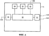
Фиг.6 показывает первый вариант осуществления дополнительного устройства,6 shows a first embodiment of an additional device,
Фиг.7 показывает второй вариант осуществления дополнительного устройства,7 shows a second embodiment of an additional device,
Фиг.8 показывает третий вариант осуществления дополнительного устройства,Fig. 8 shows a third embodiment of an additional device,
ОПИСАНИЕ ВАРИАНТОВ ОСУЩЕСТВЛЕНИЯDESCRIPTION OF EMBODIMENTS
Фиг.1 показывает устройство 1 для управления энергопотреблением первого (второго, третьего) принимающего модуля 3 (5, 7) через беспроводное или небеспроводное соединение 103 (105, 107). Первый (второй, третий) принимающий модуль 3 (5, 7) управляет первым (вторым, третьим) прибором 4 (6, 8) через обычное небеспроводное или наоборот беспроводное соединение 104 (106, 108). Передающий модуль 2 управляет первым (вторым, третьим) принимающим модулем 3 (5, 7) через обычное беспроводное или, наоборот, небеспроводное соединение 100 (101, 102), путем отправки сигнала управления функционированием через соединение 100 (101, 102). Модуль 9 обнаружения обнаруживает состояние первого (второго, третьего) прибора 4 (6, 8) через соединение 110 (111, 112) обнаружения и информирует устройство 1 через информационное соединение 109.Figure 1 shows a
Прибор 4 (6, 8) содержит, например, лампу, прибор или другое изделие, которое удаленно управляется посредством комбинации передающего модуля 2 и принимающего модуля 3 (5, 7), в зависимости от состояния прибора 4 (6, 8). Этим состоянием может быть состояние «включено», состояние «выключено», состояние подсветки или любой другой вид состояния. Модуль 9 обнаружения может содержать, например, фоторезистор, фотодиод или солнечный элемент, или он может быть выполнен с возможностью обнаруживать энергопотребление, и/или протекающий электрический ток и/или подаваемое напряжение к принимающему модулю 3 (5, 7) и/или прибору 4 (6, 8).The device 4 (6, 8) contains, for example, a lamp, a device or other product that is remotely controlled by a combination of a transmitting module 2 and a receiving module 3 (5, 7), depending on the state of the device 4 (6, 8). This state can be an on state, an off state, a backlight state, or any other kind of state. The detection module 9 may contain, for example, a photoresistor, a photodiode, or a solar cell, or it may be configured to detect power consumption and / or a flowing electric current and / or supplied voltage to the receiving module 3 (5, 7) and / or the device 4 (6, 8).
Когда, например, прибор 4 (6, 8) включен (выключен) и когда устройство 1 знает, что в предопределенный интервал времени нет необходимости выключать (включать) прибор, принимающий модуль 3 (5, 7) может быть выключен на этот предопределенный интервал времени. Это снижает среднее энергопотребление принимающего модуля 3 (5, 7). Среднее энергопотребление является энергопотреблением в единицу интервала времени, такого как час, день, неделя, месяц или год, не исключая другие интервалы времени.When, for example, the device 4 (6, 8) is turned on (off) and when the
Фиг.2 показывает дополнительное устройство 11 для управления энергопотреблением устройства 1 через беспроводное или небеспроводное соединение 113 и для управления энергопотреблением другого устройства 21, аналогичного устройству 1, через беспроводное или небеспроводное соединение 213. Устройство 1, уже описанное со ссылкой на Фиг.1, управляет энергопотреблением трех принимающих модулей 3, 5 и 7 через соединения 103, 105 и 107. Для пользы ясности, три принимающих модуля 3, 5 и 7 указаны здесь в комбинации с тремя приборами 4, 6 и 8, при этом передающий модуль 2 и модуль 9 обнаружения были опущены; показано только соединение 109. Аналогично устройству 1, устройство 21 управляет энергопотреблением трех принимающих модулей 23, 25 и 27 через соединения 203, 205 и 207. Для пользы ясности, три принимающих модуля 23, 25 и 27 указаны здесь в комбинации с тремя приборами 24, 26 и 28, при этом передающий модуль, аналогичный передающему модулю 2, и модуль обнаружения, аналогичный модулю 9 обнаружения, опущены; показано только соединение 209. Энергопотребление дополнительного устройства 11 может управляться через беспроводное или небеспроводное соединение 313.Figure 2 shows an
В минимальной ситуации, устройство 1 (21) будет управлять энергопотреблением одного принимающего модуля 3 (5, 7), а дополнительное устройство 11 будет управлять энергопотреблением одного устройства 1 (21). В более общей ситуации, устройство 1 (21) будет управлять энергопотреблением более чем одного принимающего устройства 3 (5, 7), а дополнительное устройство 11 будет управлять энергопотреблением более чем одного устройства 1 (21).In a minimal situation, device 1 (21) will control the power consumption of one receiving module 3 (5, 7), and
Фиг.3 показывает первый вариант осуществления устройства 1. Устройство 1 содержит контроллер (30) для управления энергопотреблением принимающих модулей 3, 5, и 7 через интерфейс 31 и соединения 103, 105 и 107, в ответ на обнаружение состояний приборов 4, 6 и 8. С этой стороны, устройство 1 дополнительно содержит, например, интерфейс 32 для согласования соединения 109. Устройство 1 так же содержит, например, регистратор 33, для отслеживания энергопотребления, и/или протекающего электрического тока, и/или подаваемого напряжения к принимающим модулям 3, 5 и 7 и/или к приборам 4, 6 и 8 так, чтобы получать информацию о состоянии приборов 4, 6 и 8. В качестве альтернативы, регистратор 33 может быть интегрирован в модуль 9 обнаружения или модуль 9 обнаружения может быть интегрирован в регистратор 33. Устройство 1 дополнительно содержит, например, процессор 34, который, в ответ на анализ энергопотребления, и/или протекающего электрического тока, и/или подаваемого напряжения к принимающим модулям 3, 5 и 7 и/или к приборам 4, 6 и 8, формирует статистику и/или сообщение и приспосабливает поведение устройства 1. Такой анализ может выполняться процессором 34 или может выполняться за пределами устройства 1. Более того, устройство 1 содержит, например, интерфейс 35 для согласования соединения 113.Figure 3 shows the first embodiment of the
Интерфейс 31 может быть беспроводным или небеспроводным интерфейсом 31 для управления энергопотреблением принимающих модулей 3, 5 и 7 беспроводным или небеспроводным образом. Интерфейс 31 может быть физическим и/или логическим интерфейсом 31 для управления энергопотреблением принимающих модулей 3, 5 и 7 физически (посредством переключения) и/или логически (посредством передачи команд).The
Фиг.4 показывает второй вариант осуществления устройства 1. Это устройство 1 отличается от того, что показано на Фиг.3 тем, что в этом случае устройство 1 дополнительно содержит интерфейс 37, для согласования линии 38 питания. Линия 38 питания подает питание к устройству 1, а интерфейс 37 объединен с интерфейсом 31 посредством линии 36 питания. В этом случае, интерфейс 31 является небеспроводным и физическим интерфейсом 31 и, в зависимости от результатов обнаружения, либо подает, либо не подает питание через небеспроводные соединения 103, 105 и 107 к принимающим модулям 3, 5 и 7.FIG. 4 shows a second embodiment of the
Фиг.5 показывает третий вариант осуществления устройства 1. Устройство 1 содержит контроллер (30) и интерфейс 35, уже описанные выше со ссылкой на Фиг.3. Это устройство 1 дополнительно содержит приемник 40, для приема сигналов управления функционированием, которыми обмениваются (обычно беспроводным или наоборот небеспроводным образом) между собой передающий модуль 2 и принимающие модули 3, 5 и 7. Устройство 1 дополнительно содержит детектор (41), для обнаружения состояния приборов 4, 6 и 8, в ответ на прием этих сигналов управления функционированием. Этот детектор (41) может работать в добавление к модулю 9 обнаружения, показанному на Фиг.1, или он может работать вместо этого модуля 9 обнаружения. Устройство 1 может дополнительно содержать модуль 42 преобразования, для преобразования сигнала управления функционированием в преобразованный сигнал, и/или устройство 1 дополнительно содержит передатчик 43, для передачи сигналов управления функционированием или преобразованных сигналов к принимающим модулям 3, 5 и 7. Устройство 1 дополнительно может содержать память 44 для хранения сигналов управления функционированием и/или преобразованных сигналов. Сигналы управления функционированием и/или преобразованные сигналы могут передаваться сразу после приема и/или преобразования, или после окончания или завершения интервала времени, или после того, как оно убедится, что к принимающим модулям 3, 5 и 7 подведено питание и/или они способны к приему этих сигналов управления функционированием и/или преобразованных сигналов. Передача сигналов управления функционированием и/или преобразованных сигналов может содержать однократную передачу, однократную ретрансляцию и/или повторную ретрансляцию и т.д. Контроллер (30), предпочтительно, связывается через передатчик 23, для управления энергопотреблением принимающих модулей 3, 5 и 7 посредством преобразованных сигналов. Устройство 1 дополнительно может быть предоставлено с процессором, который, в ответ на анализ трафика, обмен которым осуществляется через каждый принимающий модуль 3, 5 и 7, например, между передающим модулем 2 и каждым принимающим модулем 3, 5 и 7, формирует статистику и/или сообщение и приспосабливает поведение устройства 1. Такой анализ может быть выполнен процессором или может быть выполнен за пределами устройства 1.FIG. 5 shows a third embodiment of the
Когда прибор 4 (6, 8) включен или выключен или находится в другом состоянии, его принимающий модуль 3 (5, 7) может быть выключен посредством устройства 1 для снижения энергопотребления, либо при условии, что устройство 1 знает как долго этот принимающий модуль 3 (5, 7) может оставаться выключенным, либо при условии, что устройство 1 имеет доступ к информации, которой обмениваются между собой передающий модуль 2 и принимающий модуль 3 (5, 7), так что устройство 1 может реагировать на новую информацию, которой обмениваются между собой передающий модуль 2 и принимающий модуль 3 (5, 7), такую как новый сигнал управления функционированием, и затем обратно включить принимающий модуль 3 (5, 7).When the device 4 (6, 8) is turned on or off or is in a different state, its receiving module 3 (5, 7) can be turned off by means of a
Фиг.6 показывает первый вариант осуществления дополнительного устройства 11. Дополнительное устройство 11 содержит контроллер (50), для управления энергопотреблением устройств 1 и 21 через интерфейс 51 и соединения 113 и 213, в ответ на обнаружение состояния устройства 1 и 21 и/или принимающих модулей 3, 5 и 7 и/или приборов 4, 6 и 8. С этой стороны, дополнительное устройство 11 так же содержит, например, интерфейс 52 для согласования соединения 309. Соединение 309 может соответствовать соединению 109 или оно может быть отличным соединением для связи устройств 1 и 21 с дополнительным устройством 11. Дополнительное устройство 11 так же содержит, например, регистратор 53, для отслеживания энергопотребления, и/или протекающего электрического тока, и/или поданного напряжения к устройству 1 и 21 и/или принимающим модулям 3, 5 и 7 и/или приборам 4, 6 и 8 для получения информации о состоянии устройств 1 и 21 и/или принимающих модулей 3, 5 и 7 и/или приборов 4, 6 и 8. В качестве альтернативы, регистратор 53 может быть интегрирован в модуль 9 обнаружения или модуль 9 обнаружения может быть интегрирован в регистратор 53. Дополнительное устройство 1 так же содержит, например, процессор 54, который, в ответ на анализ энергопотребления, и/или протекающего электрического тока, и/или подаваемого напряжения к устройствам 1 и 21 и/или принимающим модулям 3, 5 и 7 и/или приборам 4, 6 и 8, формирует статистику и/или сообщение и/или приспосабливает поведение дополнительного устройства 11. Такой анализ может быть выполнен процессором 54 или может быть выполнен за пределами дополнительного устройства 11. Дополнительное устройство 11 так же содержит, например, интерфейс 55 для согласования соединения 313.6 shows a first embodiment of the
Интерфейс 51 может быть беспроводным или небеспроводным интерфейсом 51 для управления энергопотреблением устройств 1 и 21 беспроводным или небеспроводным образом. Интерфейс 51 может быть физическим и/или логическим интерфейсом 51 для управления энергопотреблением устройств 1 и 21 физически (посредством переключения) и/или логически (посредством передачи команд).
Фиг.7 показывает вариант осуществления дополнительного устройства 11. Это дополнительное устройство 11 отличается от того, что показано на Фиг.6 тем, что в этом случае, дополнительное устройство 11 так же содержит интерфейс 57 для согласования линии 58 питания. Линия 58 питания подает питание дополнительному устройству 11 и интерфейс 57 объединен с интерфейсом 51 посредством линии 56 питания. В этом случае, интерфейс 51 является небеспроводным и физическим интерфейсом 51 и, в зависимости от результатов обнаружения, либо проводит, либо не проводит питание через небеспроводные соединения 113 и 213 к устройствам 1 и 21.FIG. 7 shows an embodiment of the
Фиг.8 показывает третий вариант осуществления дополнительного устройства 11. Это дополнительное устройство 11 содержит контроллер (50) и интерфейс 55, уже описанные выше со ссылкой на Фиг. 6. Это дополнительное устройство 11 так же содержит приемник 60, для приема сигналов управления функционированием, которыми обмениваются (обычно беспроводным или наоборот небеспроводным образом) между собой передающий модуль 2 и принимающие модули 3, 5 и 7. Дополнительное устройство 11 может так же содержать модуль 61 обнаружения, для обнаружения состояния приборов 4, 6 и 8, в ответ на прием этих сигналов управления функционированием. Этот модуль 61 обнаружения может работать в добавление к модулю 9 обнаружения, показанному на Фиг. 1, или он может работать вместо этого модуля 9 обнаружения. Модуль 61 обнаружения может работать в добавление к модулю 41 обнаружения, показанному на Фиг. 5, или он может работать вместо этого модуля 41 обнаружения. Дополнительное устройство 11 может так же содержать модуль 62 преобразования, для преобразования сигналов управления функционированием в преобразованные сигналы, и/или оно может так же содержать передатчик 63, для передачи сигналов управления функционированием или преобразованных сигналов к устройствам 1 и 21 или к принимающим модулям 3, 5 и 7, возможно, через устройства 1 и 21. Дополнительное устройство 11 может так же содержать память 64, для хранения сигналов управления функционированием и/или преобразованных сигналов. Сигналы управления функционированием и/или преобразованные сигналы могут передаваться сразу после получения и/или преобразования или после окончания или прекращения интервала времени, или после того, как оно убедится, что к устройствам 1, 21 и/или к принимающим модулям 3, 5, 7 подано питание и/или, что они имеют возможность приема этих сигналов управления функционированием и/или преобразованных сигналов. Передача сигналов управления функционированием и/или преобразованных сигналов может содержать однократную передачу, однократную ретрансляцию и/или повторную ретрансляцию и т.д. Контроллер (50) предпочтительно связывается через передатчик 63, для управления энергопотреблением устройств 1 и 21 посредством преобразованных сигналов. Дополнительное устройство 11 может быть так же снабжено процессором, который в ответ на анализ трафика, обмен которым осуществляется через принимающий модуль 3, 5 и 7, между, например, передающим модулем 2 и каждым принимающим модулем 3, 5 и 7, формирует статистику и/или сообщение и приспосабливает поведение дополнительного устройства 11 и/или устройств 1 и 21. Такой анализ может быть выполнен посредством процессора или может быть выполнен за пределами дополнительного устройства 11.FIG. 8 shows a third embodiment of the
Когда прибор 4 (6, 8) включен или выключен, или находится в другом состоянии, и/или его принимающий модуль 3 (5, 7) включен или выключен, или находится в другом состоянии, и/или когда его устройство 1 включено или находится в другом состоянии, это устройство 1 может быть выключено посредством дополнительного устройства 11 для снижения энергопотребления, либо при условии, что дополнительное устройство 11 знает, как долго это устройство 1 может оставаться выключенным, либо при условии, что дополнительное устройство 11 имеет доступ к информации, которой обмениваются передающий модуль 2 и принимающий модуль 3 (5, 7) так, что дополнительное устройство 11 может отреагировать на новую информацию, которой обмениваются передающий модуль 2 и принимающий модуль 3 (5, 7), такую как новый сигнал управления функционированием, и затем обратно включить устройство 1.When the device 4 (6, 8) is turned on or off, or is in a different state, and / or its receiving module 3 (5, 7) is turned on or off, or is in a different state, and / or when its
Когда система содержит, например, дополнительное устройство из расчета на этаж здания, для управления этажом, и, из расчета на этаж, устройство из расчета на помещение, для управления помещением, питание распределяется на уровне этаж-к-помещению и, в конечном счете, к приборам. Эти приборы содержат, например, модуль освещения, объединенный с принимающими модулями с интегрированными балластными сопротивлениями под управлением ZigBee. Все оборудование связывается, например, посредством интерфейсов ZigBee. Каждое устройство может хранить список идентификаторов (например, 16-битные адреса ZigBee) модулей освещения, чье энергопотребление управляется посредством каждого устройства. Список модулей, управляемых посредством каждого устройства, может быть заранее сконфигурирован, например, используя механизм Непосредственного Соединения уровня сети ZigBee (ZigBee-NWK-layer DirectJoin) и/или механизм Связывания уровня Поддержки Приложения ZigBee (ZigBee-APS-layer Binding), механизма ZigBee Group или любого другого пригодного механизма приложения. В предпочтительном варианте осуществления, устройства автоматически узнают о модулях, которым они подают питание посредством одновременного анализа трафика управления ZigBee и результирующего текущего потребления на линиях питания. На этом этапе изучения, устройства только отслеживают энергопотребление, не отключая энергоснабжение. Таким образом, так же возможно обнаружение эксплуатационного/в режиме ожидания энергопотребления и/или обнаружение топологий линии питания, отличных от единственной «линия питания + переключение питания/передающий модуль» из расчета на модуль освещения.When the system contains, for example, an additional device based on the floor of the building, for floor management, and, based on the floor, the device based on the room, for room management, the power is distributed at the floor-to-room level and, ultimately, to appliances. These devices include, for example, a lighting module combined with receiving modules with integrated ballasts under ZigBee control. All equipment is connected, for example, through ZigBee interfaces. Each device can store a list of identifiers (for example, 16-bit ZigBee addresses) of lighting modules, whose power consumption is controlled by each device. The list of modules controlled by each device can be preconfigured, for example, using the ZigBee Direct-Link Network Layer (ZigBee-NWK-layer DirectJoin) mechanism and / or the ZigBee Application Support Level Linking (ZigBee-APS-layer Binding) mechanism, ZigBee mechanism Group or any other suitable application engine. In a preferred embodiment, the devices automatically recognize the modules to which they are powered by simultaneously analyzing ZigBee control traffic and the resulting current consumption on the power lines. At this stage of the study, devices only monitor power consumption without turning off the power supply. Thus, it is also possible to detect operational / standby power consumption and / or to detect power line topologies other than a single “power line + power switch / transmitting module” based on the lighting module.
Сами по себе устройства, по умолчанию, могут всегда оставаться включенными для отслеживания трафика управления ZigBee. Если модуль освещения выключен, устройство выключает энергоснабжение этого модуля. Когда сообщение управления затем, посредством ZigBee, посылается к одному из модулей освещения (который в текущий момент отключен от питания) устройства, устройство снова подает питание к этому модулю.Devices per se, by default, can always remain on to monitor ZigBee management traffic. If the lighting module is turned off, the device turns off the power to this module. When a control message is then sent via ZigBee to one of the lighting modules (which is currently disconnected from the power supply) of the device, the device again supplies power to this module.
Функционал устройств может быть скрыт в других компонентах. Передающий модуль может быть сконфигурирован для того, чтобы отправлять сообщения управления, посредством ZigBee, непосредственно управляемым принимающим модулям. Устройство просто работает как «модуль проверки текущего состояния» ZigBee, прослушивая сообщения, отправленные непосредственно модулям и делая выводы, на основании трафика управления и энергопотребления, о том, чтобы включить или выключить энергоснабжение конкретного модуля освещения.Functionality of devices may be hidden in other components. The transmitting module can be configured to send control messages, via ZigBee, to the directly controlled receiving modules. The device simply acts as a ZigBee “current state checking module”, listening to messages sent directly to the modules and drawing conclusions, based on control traffic and power consumption, about turning the power supply on or off for a particular lighting module.
Чтобы ограничить энергопотребление самим устройством, устройству, предпочтительно, необходимо всего лишь предоставить возможность вещания после того, как один из его модулей освещения был выключен. В то время как все модули освещения включены и к ним подается питание, устройство управления может полагаться исключительно на анализ энергопотребления (до тех пор, пока энергопотребление в режиме ожидания не обнаружено для конкретного модуля освещения).To limit the power consumption of the device itself, the device, preferably, it is only necessary to provide the possibility of broadcasting after one of its lighting modules has been turned off. While all lighting modules are turned on and powered, the control unit can rely solely on energy consumption analysis (until standby power consumption is detected for a particular lighting module).
Устройство может работать как модуль доступа. Оно может принимать трафик от передающего модуля и переадресовывать трафик модулям освещения после того, как удостоверится, что к ним подается питание. В этом случае, может потребоваться, чтобы трафик был сохранен, например, временно.The device can operate as an access module. It can receive traffic from the transmitting module and forward the traffic to the lighting modules after making sure that they are powered. In this case, it may be necessary that the traffic be saved, for example, temporarily.
Такая функциональность может быть выполнена явным образом, если устройство несет в себе Объект Приложения средства управления типа LON. Это так же может быть реализовано неявным образом, если модули освещения, так же как и принимающие модули, управляющие ими, сконфигурированы в качестве ZED-потомка устройства, являющегося маршрутизатором ZigBee.Such functionality can be performed explicitly if the device carries an Application Object of an LON-type management tool. This can also be implemented implicitly if the lighting modules, as well as the receiving modules controlling them, are configured as the ZED descendant of the device that is the ZigBee router.
Чтобы обеспечить оптимальную производительность, сообщения ZigBee модулям освещения предпочтительно должны быть «замещены» посредством устройства только когда модули освещения выключены и могут быть непосредственно приняты модулями освещения, когда они включены.To ensure optimum performance, ZigBee messages to the lighting modules should preferably be “replaced” by the device only when the lighting modules are turned off and can be directly received by the lighting modules when they are turned on.
Устройство может работать по отношению к модулям освещения как интеллектуальный модуль доступа. Оно может быть сконфигурировано с дополнительными логическими компонентами для того, чтобы анализировать команды управления, которые были только что приняты от передающего модуля, и принимать решение, подавать ли снова питание к модулю освещения. Это может помочь ограничить как энергопотребление, так и величину трафика управления ZigBee, например, в случае зашумленных или сломанных датчиков (освещения).The device can operate with respect to lighting modules as an intelligent access module. It can be configured with additional logic components in order to analyze the control commands that have just been received from the transmitting module and decide whether to apply power to the lighting module again. This can help limit both power consumption and the amount of ZigBee control traffic, for example, in the case of noisy or broken sensors (lighting).
Таким образом, необходимо подводить питание только устройствам. Все другие узлы ZigBee находятся полностью выключенными в течение времени простоя и не потребляют энергию.Therefore, only devices must be powered up. All other ZigBee nodes are completely off during downtime and do not consume power.
Устройства могут создавать физическую или логическую иерархию энергоснабжения. В физической иерархии энергоснабжения, устройства физически отсекают питание, подаваемое контролируемым ими модулям (модули освещения или другой уровень устройств, если используется), например, посредством использования реле. В логической иерархии энергоснабжения, устройства только посылают команды включения питания/выключения питания к контролируемым ими модулям.Devices can create a physical or logical hierarchy of power supply. In the physical hierarchy of power supply, devices physically cut off the power supplied to the modules they control (lighting modules or another level of devices, if used), for example, by using a relay. In the logical hierarchy of power supply, devices only send power-on / power-off commands to the modules they control.
После того как все модули освещения одного устройства управляются в режиме ожидания, устройство само переходит в режим ожидания, и дополнительное устройство, которое является следующим выше в иерархии, может его выключить. Могут поддерживаться несколько уровней иерархии энергоснабжения.After all the lighting modules of one device are controlled in standby mode, the device itself goes into standby mode, and the additional device, which is the next higher in the hierarchy, can turn it off. Several levels of the power supply hierarchy can be supported.
Команды включения от передающих модулей в каждом помещении должны быть приняты дополнительным устройством, управляющим этажом так, что оно может принять их и подать питание соответствующему устройству, управляющему помещением, так же как и подать питание соответствующим модулям освещения. Дополнительное устройство, управляющее этажом, может иметь необходимость хранить информацию о том, какой передающий модуль управляет модулями освещения какого устройства. Эта информация может быть собрана дополнительным устройством или может быть выяснена заранее, и т.д.The switching commands from the transmitting modules in each room must be received by an additional device that controls the floor so that it can receive them and supply power to the corresponding device that controls the room, as well as supply power to the corresponding lighting modules. An additional device that controls the floor may need to store information about which transmitter module controls the lighting modules of which device. This information can be collected by an additional device or can be found out in advance, etc.
Устройствам нет необходимости получать их команды посредством ZigBee, но они могут получать их посредством проводной связи (например, Ethernet) и иметь узел управления ZigBee, который транслирует команды, передаваемые проводным образом, в команды ZigBee.Devices do not need to receive their commands via ZigBee, but they can receive them via wired communication (for example, Ethernet) and have a ZigBee control node that translates wired commands to ZigBee commands.
Устройство может узнать о нормальном энергопотреблении присоединенных модулей освещения и сформировать сообщения диагностики или сигналы всякий раз, когда энергопотребление радикально меняется, что может быть признаком сломанных или неисправных источников освещения. Это сообщение так же может быть выпущено, если заранее записанное поведение, такое как, время пуска ламп, таких как разрядная лампа высокой интенсивности, вышло за пределы допуска, или когда лампе необходим многократный запуск, чтобы начать свечение, и т.д., указывающие на то, что скоро необходимо поменять лампу.The device can learn about the normal power consumption of the connected lighting modules and generate diagnostic messages or signals whenever the power consumption changes dramatically, which may be a sign of broken or faulty light sources. This message can also be issued if a pre-recorded behavior, such as the start-up time of lamps, such as a high-intensity discharge lamp, is out of tolerance, or when the lamp needs to be repeatedly started to start glowing, etc., indicating that soon you need to change the lamp.
Точно такой же механизм так же может использоваться для других типов приборов, а могут использоваться отличные беспроводные или небеспроводные технологии. Технология ZigBee является, таким образом, только примером, и альтернативные технологии не исключаются.Exactly the same mechanism can also be used for other types of devices, and excellent wireless or non-wireless technologies can be used. ZigBee technology is thus only an example, and alternative technologies are not excluded.
Каждый интерфейс может быть простым подсоединением или объединяющим, более комплексный пассивный или активный преобразователь, или быть высокоструктурированным интерфейсом, содержащим свой собственный процессор. Каждый модуль управления может быть простым не программируемым модулем управления, более комплексным программируемым модулем управления или высокоструктурированным модулем управления со способностью к обучению. Каждый модуль обнаружения и регистратор может быть простым устройством сравнения, более комплексным фильтром/вычислительной машиной или высокоструктурированным анализатором.Each interface can be a simple connection or a unifying, more complex passive or active converter, or a highly structured interface containing its own processor. Each control module can be a simple non-programmable control module, a more complex programmable control module, or a highly structured learning module with learning ability. Each detection module and recorder can be a simple comparison device, a more complex filter / computer, or a highly structured analyzer.
Подводя итог вышесказанному, среднее энергопотребление принимающих модулей 3, 5, 7 для управления приборами 4, 6, 8 в ответ на сигналы управления функционированием от передающего модуля 2 может быть снижено посредством ввода устройств 1, 21 для управления энергопотреблением принимающих модулей 3, 5, 7 в ответ на обнаружение состояний приборов 4, 6, 8. Устройства 1 могут содержать контроллеры (30), для управления энергопотреблением беспроводным, небеспроводным, физическим и/или логическим образом. Устройства 1 могут содержать регистраторы 33, для отслеживания энергопотребления, электрических токов и/или напряжения на принимающих модулях 3, 5, 7 и/или приборах 4, 6, 8. Устройства 1 могут содержать приемники 40, детекторы 41, модули 42 преобразования и передатчики 43 для приема сигналов управления функционированием, обнаружения состояний приборов 4, 6, 8, преобразования сигналов управления функционированием в преобразованные сигналы, и передачи сигналов управления функционированием или преобразованных сигналов к принимающим модулям 3, 5, 7 для управления энергопотреблением принимающих модулей 3, 5, 7 посредством переданных сигналов, при этом переданные сигналы соответствуют сигналам управления питанием.To summarize the above, the average power consumption of the receiving
В то время как изобретение было проиллюстрировано и подробно описано в чертежах и вышеизложенном описании, такая иллюстрация и описание должны рассматриваться как пояснительные или в качестве примеров, которые не являются ограничивающими; изобретение не ограничено раскрытыми вариантами осуществления. Например, возможно выполнить изобретение в вариантах осуществления, при этом различные части различных раскрытых вариантов осуществления объединены в новый вариант осуществления.While the invention has been illustrated and described in detail in the drawings and the foregoing description, such illustration and description should be construed as illustrative or as examples, which are not limiting; the invention is not limited to the disclosed embodiments. For example, it is possible to carry out the invention in embodiments, while various parts of the various disclosed embodiments are combined in a new embodiment.
Другие варианты раскрытых вариантов осуществления могут быть поняты и осуществлены специалистами в соответствующей области в практическом применении заявленного изобретения, из изучения чертежей, раскрытия и приложенной формулы изобретения. В формуле изобретения, использование глагола «содержать» и его спряжений не исключает других элементов или этапов, а предлоги единственного числа не исключают множество. Единственный процессор или другой модуль может выполнять функции нескольких пунктов, перечисленных в формуле изобретения. Всего лишь факт того, что определенные меры перечислены во взаимно отличных зависимых пунктах формулы изобретения, не указывает на то, что комбинация этих мер не может быть использована для получения преимущества. Компьютерная программа может храниться/распространяться на пригодном носителе, таком как оптический носитель данных, или твердотельном носителе, поставляемом совместно с или как часть другого аппаратного средства, но может так же распространяться в других формах, таких как через Интернет или другие проводные или беспроводные телекоммуникационные системы. Любые ссылочные символы в формуле изобретения не должны толковаться как ограничивающие объем.Other embodiments of the disclosed embodiments may be understood and practiced by those skilled in the art in the practice of the claimed invention, from a study of the drawings, disclosure and appended claims. In the claims, the use of the verb “contain” and its conjugations does not exclude other elements or steps, and the prepositions of the singular do not exclude a plurality. A single processor or other module may fulfill the functions of several items listed in the claims. The mere fact that certain measures are listed in mutually different dependent claims does not indicate that a combination of these measures cannot be used to take advantage. The computer program may be stored / distributed on a suitable medium, such as an optical data medium, or a solid state medium, supplied with or as part of other hardware, but may also be distributed in other forms, such as via the Internet or other wired or wireless telecommunication systems . Any reference characters in the claims should not be construed as limiting the scope.
Claims (15)
Applications Claiming Priority (3)
| Application Number | Priority Date | Filing Date | Title |
|---|---|---|---|
| EP08101293 | 2008-02-05 | ||
| EP08101293.2 | 2008-02-05 | ||
| PCT/IB2009/050403 WO2009098628A1 (en) | 2008-02-05 | 2009-02-02 | Controlling the power consumption of a receiving unit |
Publications (2)
| Publication Number | Publication Date |
|---|---|
| RU2010136978A RU2010136978A (en) | 2012-03-20 |
| RU2503125C2 true RU2503125C2 (en) | 2013-12-27 |
Family
ID=40627483
Family Applications (1)
| Application Number | Title | Priority Date | Filing Date |
|---|---|---|---|
| RU2010136978/07A RU2503125C2 (en) | 2008-02-05 | 2009-02-02 | Control of power consumption of receiving module |
Country Status (6)
| Country | Link |
|---|---|
| US (1) | US9357497B2 (en) |
| EP (1) | EP2241014B1 (en) |
| JP (1) | JP6009734B2 (en) |
| CN (1) | CN101939920B (en) |
| RU (1) | RU2503125C2 (en) |
| WO (1) | WO2009098628A1 (en) |
Cited By (1)
| Publication number | Priority date | Publication date | Assignee | Title |
|---|---|---|---|---|
| RU2690750C1 (en) * | 2017-12-07 | 2019-06-05 | Гига-Байт Текнолоджи Ко., Лтд. | Method for powering the system and its computer system |
Families Citing this family (3)
| Publication number | Priority date | Publication date | Assignee | Title |
|---|---|---|---|---|
| DE102009050170B4 (en) * | 2009-10-21 | 2013-08-01 | Diehl Ako Stiftung & Co. Kg | Home automation and home information system |
| CN103380602B (en) * | 2011-02-28 | 2017-07-14 | 飞利浦灯具控股公司 | Operation and the method for the device in debugging ZigBee-network |
| US9319249B2 (en) | 2014-08-27 | 2016-04-19 | eTopus Technology Inc. | Receiver for high speed communication channel |
Citations (10)
| Publication number | Priority date | Publication date | Assignee | Title |
|---|---|---|---|---|
| EP0426452A2 (en) * | 1989-11-01 | 1991-05-08 | Nec Corporation | Battery saving system for interrupting power supplies at intervals variable with traffic pattern |
| US5081402A (en) * | 1991-02-22 | 1992-01-14 | Comfortex Corporation | Low power consumption wireless data transmission and control system |
| GB2271691A (en) * | 1992-09-21 | 1994-04-20 | Oconnor P J | Synchronisation of a radio telemetry system |
| GB2347300A (en) * | 1999-02-26 | 2000-08-30 | Kim Seong Soo | Cellular phone with lamps |
| GB2379365A (en) * | 2001-07-23 | 2003-03-05 | Nec Corp | Reducing power consumption in a mobile station with a short range link |
| WO2005117389A1 (en) * | 2004-05-24 | 2005-12-08 | Koninklijke Philips Electronics N.V. | Device abstraction layer for local networking system |
| US20060154598A1 (en) * | 2003-06-11 | 2006-07-13 | Rudland Philip A | Configuring a radio network for selective broadcast |
| US20060215345A1 (en) * | 2005-03-14 | 2006-09-28 | The Regents Of The University Of California | Wireless network control for building lighting system |
| WO2007082017A2 (en) * | 2006-01-11 | 2007-07-19 | Fisher-Rosemount Systems, Inc. | Control system with predictive field device response time over a wireless network |
| RU2313123C2 (en) * | 2002-05-08 | 2007-12-20 | Майкрософт Корпорейшн | Method and system for controlling power consumption of network interface module in a wireless computing device |
Family Cites Families (43)
| Publication number | Priority date | Publication date | Assignee | Title |
|---|---|---|---|---|
| US3987398A (en) * | 1974-07-05 | 1976-10-19 | Premier Cablevision Limited | Remote disconnect-reconnect tap for cable television systems |
| US4737851A (en) * | 1987-04-24 | 1988-04-12 | Rca Corporation | On/off control circuitry for television |
| US4734771A (en) * | 1987-04-24 | 1988-03-29 | Rca Corporation | Start-up control circuitry for a television apparatus |
| US4955038A (en) * | 1988-12-09 | 1990-09-04 | Dallas Semiconductor Corporation | Low-power RF receiver |
| US5448756A (en) * | 1992-07-02 | 1995-09-05 | Motorola, Inc. | High frequency battery saver for a radio receiver |
| US5606728A (en) * | 1995-06-05 | 1997-02-25 | Motorola, Inc. | Method and apparatus for reducing power consumption in a selective call radio |
| US5794137A (en) * | 1995-07-17 | 1998-08-11 | Ericsson Inc. | Method for increasing stand-by time in portable radiotelephones |
| US5760558A (en) * | 1995-07-24 | 1998-06-02 | Popat; Pradeep P. | Solar-powered, wireless, retrofittable, automatic controller for venetian blinds and similar window converings |
| US6211627B1 (en) * | 1997-07-29 | 2001-04-03 | Michael Callahan | Lighting systems |
| US7064498B2 (en) * | 1997-08-26 | 2006-06-20 | Color Kinetics Incorporated | Light-emitting diode based products |
| US6211626B1 (en) * | 1997-08-26 | 2001-04-03 | Color Kinetics, Incorporated | Illumination components |
| JP3792066B2 (en) * | 1999-03-31 | 2006-06-28 | シャープ株式会社 | Low power consumption peripherals |
| US6360085B1 (en) * | 1999-09-30 | 2002-03-19 | Conexant Systems, Inc. | System and method for receiving a signal |
| US7058833B1 (en) * | 2000-01-18 | 2006-06-06 | Paradyne Corp. | System and method for minimized power consumption for frame and cell data transmission systems |
| JP3994615B2 (en) * | 2000-03-15 | 2007-10-24 | ソニー株式会社 | Remote control receiving apparatus and method |
| KR100376131B1 (en) * | 2000-09-22 | 2003-03-15 | 삼성전자주식회사 | Consumption power saving apparatus and controlling method in a stand-by mode |
| JP4472886B2 (en) | 2001-03-27 | 2010-06-02 | 富士通株式会社 | Image reading apparatus, image reading system, image reading method, computer-readable recording medium storing program, and program |
| FI20010760A0 (en) * | 2001-04-11 | 2001-04-11 | Nokia Corp | Method for receiving a radio frequency (RF) signal and RF receiver |
| US7027796B1 (en) * | 2001-06-22 | 2006-04-11 | Rfmd Wpan, Inc. | Method and apparatus for automatic fast locking power conserving synthesizer |
| JP2003110716A (en) * | 2001-09-27 | 2003-04-11 | Teac Corp | Electric appliance monitor system |
| US7421257B1 (en) * | 2001-11-30 | 2008-09-02 | Stragent, Llc | Receiver scheduling in ad hoc wireless networks |
| JP3675394B2 (en) * | 2001-11-30 | 2005-07-27 | ソニー株式会社 | Communication device |
| AU2002366405A1 (en) * | 2001-12-14 | 2003-06-30 | Koninklijke Philips Electronics N.V. | Wireless data communication bus system |
| US6993393B2 (en) * | 2001-12-19 | 2006-01-31 | Cardiac Pacemakers, Inc. | Telemetry duty cycle management system for an implantable medical device |
| US6943667B1 (en) * | 2002-02-25 | 2005-09-13 | Palm, Inc. | Method for waking a device in response to a wireless network activity |
| GB0205236D0 (en) * | 2002-03-06 | 2002-04-17 | Koninkl Philips Electronics Nv | Radio apparatus system and method of operation |
| AU2003303008A1 (en) | 2002-12-16 | 2004-07-09 | Koninklijke Philips Electronics N.V. | System and method for lighting control network recovery from master failure |
| US7340615B2 (en) * | 2003-01-31 | 2008-03-04 | Microsoft Corporation | Method and apparatus for managing power in network interface modules |
| US7929985B2 (en) * | 2003-05-01 | 2011-04-19 | Telefonaktiebolaget Lm Ericsson (Publ) | Multiple antenna receiver |
| MXPA06000121A (en) * | 2003-07-02 | 2006-04-27 | Johnson & Son Inc S C | Lamp and bulb for illumination and ambiance lighting. |
| US7319867B2 (en) * | 2003-09-15 | 2008-01-15 | Atheros Communications, Inc. | Method and apparatus for wake on wireless systems |
| US8024584B2 (en) * | 2003-10-01 | 2011-09-20 | Ati Technologies Ulc | Remote connection system capable of generating a wake-up command and method thereof |
| US6990362B2 (en) * | 2003-12-16 | 2006-01-24 | Motorola, Inc. | Communication unit energy conservation apparatus and method |
| WO2006040390A1 (en) * | 2004-10-15 | 2006-04-20 | Nokia Corporation | Reduction of power consumption in wireless communication terminals |
| US7860527B2 (en) * | 2005-05-12 | 2010-12-28 | Qualcomm Incorporated | Method and apparatus for receiving data and paging from multiple wireless communication systems |
| US7881755B1 (en) * | 2005-05-26 | 2011-02-01 | Marvell International Ltd. | Wireless LAN power savings |
| KR20080026126A (en) | 2005-06-02 | 2008-03-24 | 코닌클리즈케 필립스 일렉트로닉스 엔.브이. | Lighting system and method for controlling a lighting system |
| KR100736044B1 (en) * | 2005-09-01 | 2007-07-06 | 삼성전자주식회사 | Method and apparatus for managing power in wireless device |
| JP4704877B2 (en) | 2005-10-03 | 2011-06-22 | 三菱電機株式会社 | Terminal and terminal communication method |
| US7590432B2 (en) * | 2005-10-06 | 2009-09-15 | Broadcom Corporation | Mobile communication device with low power receiver for signal detection |
| US7504952B2 (en) * | 2005-12-28 | 2009-03-17 | Sandlinks Ltd. | Wide band RFID system with tag on flexible label |
| US20070238437A1 (en) * | 2006-04-10 | 2007-10-11 | Nokia Corporation | Delayed host wakeup for wireless communications device |
| CN100446603C (en) * | 2006-07-07 | 2008-12-24 | 华为技术有限公司 | Mobile terminal power consumption control system and method |
-
2009
- 2009-02-02 JP JP2010544838A patent/JP6009734B2/en active Active
- 2009-02-02 WO PCT/IB2009/050403 patent/WO2009098628A1/en active Application Filing
- 2009-02-02 RU RU2010136978/07A patent/RU2503125C2/en not_active IP Right Cessation
- 2009-02-02 EP EP09707497.5A patent/EP2241014B1/en active Active
- 2009-02-02 CN CN200980104302.0A patent/CN101939920B/en active Active
- 2009-02-02 US US12/865,438 patent/US9357497B2/en active Active
Patent Citations (10)
| Publication number | Priority date | Publication date | Assignee | Title |
|---|---|---|---|---|
| EP0426452A2 (en) * | 1989-11-01 | 1991-05-08 | Nec Corporation | Battery saving system for interrupting power supplies at intervals variable with traffic pattern |
| US5081402A (en) * | 1991-02-22 | 1992-01-14 | Comfortex Corporation | Low power consumption wireless data transmission and control system |
| GB2271691A (en) * | 1992-09-21 | 1994-04-20 | Oconnor P J | Synchronisation of a radio telemetry system |
| GB2347300A (en) * | 1999-02-26 | 2000-08-30 | Kim Seong Soo | Cellular phone with lamps |
| GB2379365A (en) * | 2001-07-23 | 2003-03-05 | Nec Corp | Reducing power consumption in a mobile station with a short range link |
| RU2313123C2 (en) * | 2002-05-08 | 2007-12-20 | Майкрософт Корпорейшн | Method and system for controlling power consumption of network interface module in a wireless computing device |
| US20060154598A1 (en) * | 2003-06-11 | 2006-07-13 | Rudland Philip A | Configuring a radio network for selective broadcast |
| WO2005117389A1 (en) * | 2004-05-24 | 2005-12-08 | Koninklijke Philips Electronics N.V. | Device abstraction layer for local networking system |
| US20060215345A1 (en) * | 2005-03-14 | 2006-09-28 | The Regents Of The University Of California | Wireless network control for building lighting system |
| WO2007082017A2 (en) * | 2006-01-11 | 2007-07-19 | Fisher-Rosemount Systems, Inc. | Control system with predictive field device response time over a wireless network |
Cited By (1)
| Publication number | Priority date | Publication date | Assignee | Title |
|---|---|---|---|---|
| RU2690750C1 (en) * | 2017-12-07 | 2019-06-05 | Гига-Байт Текнолоджи Ко., Лтд. | Method for powering the system and its computer system |
Also Published As
| Publication number | Publication date |
|---|---|
| US20100325456A1 (en) | 2010-12-23 |
| RU2010136978A (en) | 2012-03-20 |
| JP6009734B2 (en) | 2016-10-19 |
| JP2011512615A (en) | 2011-04-21 |
| WO2009098628A1 (en) | 2009-08-13 |
| EP2241014A1 (en) | 2010-10-20 |
| CN101939920B (en) | 2016-01-06 |
| EP2241014B1 (en) | 2016-11-02 |
| CN101939920A (en) | 2011-01-05 |
| US9357497B2 (en) | 2016-05-31 |
Similar Documents
| Publication | Publication Date | Title |
|---|---|---|
| US10034340B2 (en) | Electrical lighting system power control | |
| JP2018186089A (en) | Device for supplying power to electricity consumption apparatus via data connection | |
| RU2530664C2 (en) | Method for controlling transmissions from resource-restricted device and batteryless device | |
| US10986575B2 (en) | System for communication with devices on a network to minimize power consumption | |
| JP6801005B2 (en) | Scheduled communication with resource providers and home area networks | |
| WO2017165906A1 (en) | Method and apparatus for a network and device discovery | |
| RU2503125C2 (en) | Control of power consumption of receiving module | |
| US20090135753A1 (en) | Power-conserving network device for advanced metering infrastructure | |
| WO2016166735A1 (en) | Smart batteries | |
| CN104394465A (en) | Method for waking up stand-by state and equipment | |
| JP2022508471A (en) | Signal repeater device capable of operating in low power repeater operating mode | |
| JP2018151880A (en) | Sensor device and sensor network system | |
| JP2013017264A (en) | Electric power supply apparatus, electric power management system, electric power management method, and electric power management program | |
| JP2008166249A (en) | Control device of electric equipment and its power source socket | |
| WO2011118100A1 (en) | Base station apparatus | |
| JP2012074847A (en) | Communication device, start-up node and system | |
| CN114222330A (en) | Wireless sensor network communication system | |
| JP6303062B1 (en) | Sensor device | |
| CN117155466B (en) | Control method, system, medium and equipment of optical fiber communication equipment | |
| US20220150826A1 (en) | Method for operating a wireless field-device network | |
| JP6303061B1 (en) | Sensor device | |
| KR20230124198A (en) | Local network based smart plug system for data sharing | |
| JP3829796B2 (en) | Communication adapter device | |
| JP2019071781A (en) | Management system, management method, apparatus, and control unit | |
| KR20170014859A (en) | Apparatus and method for bidirectional communication using low power |
Legal Events
| Date | Code | Title | Description |
|---|---|---|---|
| PD4A | Correction of name of patent owner | ||
| PC41 | Official registration of the transfer of exclusive right |
Effective date: 20170315 |
|
| MM4A | The patent is invalid due to non-payment of fees |
Effective date: 20210203 |