RU2496609C2 - Axially adjusted tool holder - Google Patents
Axially adjusted tool holder Download PDFInfo
- Publication number
- RU2496609C2 RU2496609C2 RU2009134157/02A RU2009134157A RU2496609C2 RU 2496609 C2 RU2496609 C2 RU 2496609C2 RU 2009134157/02 A RU2009134157/02 A RU 2009134157/02A RU 2009134157 A RU2009134157 A RU 2009134157A RU 2496609 C2 RU2496609 C2 RU 2496609C2
- Authority
- RU
- Russia
- Prior art keywords
- main body
- movable part
- adjusting ring
- tool holder
- tool
- Prior art date
Links
Images
Classifications
-
- B—PERFORMING OPERATIONS; TRANSPORTING
- B23—MACHINE TOOLS; METAL-WORKING NOT OTHERWISE PROVIDED FOR
- B23B—TURNING; BORING
- B23B31/00—Chucks; Expansion mandrels; Adaptations thereof for remote control
- B23B31/02—Chucks
- B23B31/028—Chucks the axial positioning of the tool being adjustable
-
- B—PERFORMING OPERATIONS; TRANSPORTING
- B23—MACHINE TOOLS; METAL-WORKING NOT OTHERWISE PROVIDED FOR
- B23B—TURNING; BORING
- B23B31/00—Chucks; Expansion mandrels; Adaptations thereof for remote control
- B23B31/02—Chucks
- B23B31/10—Chucks characterised by the retaining or gripping devices or their immediate operating means
- B23B31/107—Retention by laterally-acting detents, e.g. pins, screws, wedges; Retention by loose elements, e.g. balls
- B23B31/1075—Retention by screws
-
- Y—GENERAL TAGGING OF NEW TECHNOLOGICAL DEVELOPMENTS; GENERAL TAGGING OF CROSS-SECTIONAL TECHNOLOGIES SPANNING OVER SEVERAL SECTIONS OF THE IPC; TECHNICAL SUBJECTS COVERED BY FORMER USPC CROSS-REFERENCE ART COLLECTIONS [XRACs] AND DIGESTS
- Y10—TECHNICAL SUBJECTS COVERED BY FORMER USPC
- Y10T—TECHNICAL SUBJECTS COVERED BY FORMER US CLASSIFICATION
- Y10T279/00—Chucks or sockets
- Y10T279/17—Socket type
- Y10T279/17111—Fluid-conduit drill holding
-
- Y—GENERAL TAGGING OF NEW TECHNOLOGICAL DEVELOPMENTS; GENERAL TAGGING OF CROSS-SECTIONAL TECHNOLOGIES SPANNING OVER SEVERAL SECTIONS OF THE IPC; TECHNICAL SUBJECTS COVERED BY FORMER USPC CROSS-REFERENCE ART COLLECTIONS [XRACs] AND DIGESTS
- Y10—TECHNICAL SUBJECTS COVERED BY FORMER USPC
- Y10T—TECHNICAL SUBJECTS COVERED BY FORMER US CLASSIFICATION
- Y10T279/00—Chucks or sockets
- Y10T279/17—Socket type
- Y10T279/17931—Screw threaded
- Y10T279/17941—Nut lock
- Y10T279/17948—Threaded sleeve
-
- Y—GENERAL TAGGING OF NEW TECHNOLOGICAL DEVELOPMENTS; GENERAL TAGGING OF CROSS-SECTIONAL TECHNOLOGIES SPANNING OVER SEVERAL SECTIONS OF THE IPC; TECHNICAL SUBJECTS COVERED BY FORMER USPC CROSS-REFERENCE ART COLLECTIONS [XRACs] AND DIGESTS
- Y10—TECHNICAL SUBJECTS COVERED BY FORMER USPC
- Y10T—TECHNICAL SUBJECTS COVERED BY FORMER US CLASSIFICATION
- Y10T279/00—Chucks or sockets
- Y10T279/17—Socket type
- Y10T279/17991—Adjustable length or size
-
- Y—GENERAL TAGGING OF NEW TECHNOLOGICAL DEVELOPMENTS; GENERAL TAGGING OF CROSS-SECTIONAL TECHNOLOGIES SPANNING OVER SEVERAL SECTIONS OF THE IPC; TECHNICAL SUBJECTS COVERED BY FORMER USPC CROSS-REFERENCE ART COLLECTIONS [XRACs] AND DIGESTS
- Y10—TECHNICAL SUBJECTS COVERED BY FORMER USPC
- Y10T—TECHNICAL SUBJECTS COVERED BY FORMER US CLASSIFICATION
- Y10T409/00—Gear cutting, milling, or planing
- Y10T409/30—Milling
- Y10T409/30952—Milling with cutter holder
Landscapes
- Engineering & Computer Science (AREA)
- Mechanical Engineering (AREA)
- Jigs For Machine Tools (AREA)
- Gripping On Spindles (AREA)
- Cutting Tools, Boring Holders, And Turrets (AREA)
- Processing Of Stones Or Stones Resemblance Materials (AREA)
Abstract
Description
Изобретение относится к области изготовления моноблочных, модульных или других держателей инструментов, применяемых в многошпиндельных многопостовых станках для абсолютно одинаковой установки инструментов на таких станках, в частности к держателю инструмента с осевой регулировкой.The invention relates to the manufacture of monoblock, modular or other tool holders used in multi-spindle multi-post machines for exactly the same installation of tools on such machines, in particular to a tool holder with axial adjustment.
Как правило, осевую регулировку инструментов осуществляют при помощи регулировочных втулок, установленных в держателях инструментов.As a rule, the axial adjustment of the tools is carried out using the adjusting sleeves installed in the tool holders.
Инструменты, используемые на многошпиндельных станках для одновременного изготовления идентичных деталей, требуют исключительно точной осевой регулировки, чтобы строго соблюдать операции обработки различных деталей, а именно операции фрезеровки, расточки, контурной обработки и т.д.The tools used on multi-spindle machines for the simultaneous manufacture of identical parts require extremely precise axial adjustment in order to strictly observe the processing operations of various parts, namely the operations of milling, boring, contouring, etc.
В таких станках каждый инструмент необходимо предварительно идеально отрегулировать по длине и абсолютно идентично от одного шпинделя к другому, то есть с одинаковой точностью.In such machines, each tool must first be perfectly adjusted in length and absolutely identical from one spindle to another, that is, with the same accuracy.
В документе FR 2590819 описано устройство, содержащее патрон с посадочным приспособлением типа стандартного американского конуса, конуса Морзе или конуса с цилиндрическим хвостовиком и других типов для установки в шпиндели станка, в конец которого, противоположный посадочному приспособлению, заходит подвижная деталь моноблочного или модульного типа, предназначенная для установки в ней инструмента. В этом устройстве приемное гнездо подвижной детали патрона выполнено в виде двух отверстий разного диаметра, большее из которых выполнено от передней стороны патрона и соединено с меньшим отверстием внутри указанного патрона, причем эти отверстия имеют такую длину, которая обеспечивает длинную центровку подвижной детали. Кроме того, на уровне большего отверстия патрон оборудован с одной стороны по меньшей мере двумя винтами блокировки и регулировки подвижной детали, взаимодействующими с направленными в противоположные стороны наклонными пазами сферической формы, а с другой стороны - по меньшей мере одним направляющим элементом, выступающим в одно из отверстий и взаимодействующим с соответствующим пазом подвижной детали.The document FR 2590819 describes a device comprising a chuck with a landing gear such as a standard American cone, Morse taper or cone with a cylindrical shank and other types for installation in the machine spindles, at the end of which, opposite the landing gear, a movable piece of a monoblock or modular type is inserted, designed to install a tool in it. In this device, the receiving socket of the moving part of the cartridge is made in the form of two holes of different diameters, the larger of which is made from the front side of the cartridge and connected to a smaller hole inside the specified cartridge, and these holes are of such length that provides a long alignment of the moving part. In addition, at the level of the larger hole, the cartridge is equipped on the one hand with at least two locking and adjustment screws for the movable part, interacting with the spherical shaped inclined grooves directed in opposite directions, and on the other hand, with at least one guide element protruding into one of holes and interacting with the corresponding groove of the moving part.
Это устройство позволяет существенно повысить точность установки, но является относительно сложным, поэтому установка и регулировка инструмента занимают относительно большое время, что приводит к увеличению времени подготовки, в частности, для оборудования многошпиндельных и многопостовых станков.This device can significantly increase the accuracy of the installation, but is relatively complicated, so the installation and adjustment of the tool takes a relatively long time, which leads to an increase in the preparation time, in particular, for the equipment of multi-spindle and multi-post machines.
Из документа CA 972943 известен также держатель быстросъемного инструмента для сверления и зенковки, в котором быструю смену осуществляют при помощи нескольких удерживающих шариков, которые можно привести в положение высвобождения инструмента путем перемещения муфты, но которые не могут производить затягивание хвостовика инструмента, поскольку они не обеспечивают достаточную жесткость установки.A holder of a quick-detachable tool for drilling and countersink is also known from document CA 972943, in which a quick change is carried out with the help of several holding balls, which can be brought into the position of release of the tool by moving the coupling, but which cannot tighten the tool shaft, since they do not provide sufficient rigidity of installation.
Действительно, такое затягивание хвостовика инструмента при помощи устройства быстрой смены не совместимо с жесткой установкой, так как невозможно производить регулировку при помощи гайки, жестко соединенной с обоймой, в которой находятся шарики.Indeed, such a tightening of the tool shank with a quick change device is not compatible with a rigid installation, since it is impossible to make adjustments using a nut rigidly connected to a holder in which the balls are located.
В этом документе CA 972943 абсолютно не предусмотрено зажимное приспособление, которое могло бы взаимодействовать с соответствующей частью подвижной детали. Действительно, зажимной винт держателя муфты средства быстрой смены не может служить для блокировки подвижной детали после регулировки. Этот винт предназначен исключительно для удержания держателя, на котором установлена муфта, обеспечивающая быструю установку и снятие, и этот винт не предназначен для затягивания хвостовика инструмента, который стал бы несъемным.In this document CA 972943 there is absolutely no provision for a clamping device that could interact with the corresponding part of the movable part. Indeed, the clamping screw of the quick change coupler clutch holder cannot serve to lock the movable part after adjustment. This screw is intended solely to hold the holder on which the sleeve is mounted for quick installation and removal, and this screw is not intended to tighten the tool shank, which would become non-removable.
Кроме того, в документе FR 1595136 описано устройство регулировки, в котором средство перемещения инструмента в держателе не связано в поступательном движении с корпусом держателя инструмента и регулировку можно производить только в одном направлении путем более или менее сильного затягивания этого средства на хвостовике инструмента. В результате регулировка получается менее точной, в частности, по причине полной независимости этого средства перемещения от держателя инструмента.In addition, document FR 1595136 describes an adjustment device in which the tool moving means in the holder is not connected in translational motion with the tool holder body and the adjustment can be made in only one direction by more or less tightening this tool on the tool shank. As a result, the adjustment is less accurate, in particular, due to the complete independence of this means of movement from the tool holder.
Настоящее изобретение направлено на устранение этих недостатков путем создания держателя инструмента с осевой регулировкой, имеющего простую конструкцию и обеспечивающего быструю установку.The present invention addresses these drawbacks by providing an axially adjustable tool holder with a simple structure and quick installation.
Поставленная задача решается тем, что в держателе инструмента с осевой регулировкой, содержащем основной корпус с патроном, в гнезде которого установлена с возможностью скольжения подвижная деталь для установки инструмента, согласно изобретению подвижная деталь для установки инструмента установлена с возможностью поступательного перемещения при взаимодействии с регулировочным кольцом, выполненным в виде втулки с внутренней резьбой и установленным посредством шарикового подшипника на конце основного корпуса, на котором имеется гнездо для установки указанной подвижной детали, с возможностью свободного вращения без поступательного перемещения, при этом шариковый подшипник имеет гарантированный рабочий люфт, обеспечивающий при затягивании подвижной детали прижатие ближней стороны регулировочной втулки к соответствующему дальнему наружному опорному заплечику основного корпуса, при этом подвижная деталь выполнена с возможностью фиксации в рабочем положении после регулировки посредством по меньшей мере одного зажимного приспособления, взаимодействующего с соответствующей частью подвижной детали.The problem is solved in that in the tool holder with axial adjustment, containing the main body with a cartridge, in the socket of which a movable part for installing the tool is mounted with sliding possibility, according to the invention, the mobile part for installing the tool is mounted with the possibility of translational movement when interacting with the adjustment ring, made in the form of a sleeve with an internal thread and installed by means of a ball bearing at the end of the main body, on which there is a it is suitable for mounting said movable part, with the possibility of free rotation without translational movement, while the ball bearing has a guaranteed working play, which ensures that, while tightening the movable part, the near side of the adjusting sleeve is pressed against the corresponding distant outer supporting shoulder of the main body, while the movable part is made with the possibility of fixation in working position after adjustment by means of at least one clamping device interacting with relevant part of the moving part.
Изобретение будет более понятно из нижеследующего описания предпочтительного варианта его осуществления, представленного в качестве неограничивающего примера со ссылками на прилагаемые схематичные чертежи.The invention will be more apparent from the following description of a preferred embodiment, presented by way of non-limiting example with reference to the accompanying schematic drawings.
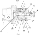
На фиг.1 показан держатель инструмента в соответствии с настоящим изобретением, вид в перспективе с пространственным разделением деталей;1 shows a tool holder in accordance with the present invention, a perspective view with a spatial separation of the parts;
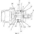
на фиг.2 - держатель инструмента в установленном положении в разрезе по зажимному приспособлению;figure 2 - tool holder in the installed position in the context of the clamping device;
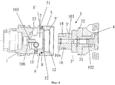
на фиг.3 - то же, что на фиг.2, но в разрезе по элементам, обеспечивающим возможность поступательного перемещения без вращения подвижной детали;figure 3 is the same as in figure 2, but in the context of the elements, providing the possibility of translational movement without rotation of the moving part;
на фиг.4 - держатель инструмента в разрезе, как на фиг.3, но разобранном виде.figure 4 is a tool holder in section, as in figure 3, but in a disassembled form.
Держатель инструмента с осевой регулировкой содержит основной корпус 1 с патроном, в гнезде 2 которого установлена с возможностью поступательного перемещения подвижная деталь 3 для установки инструмента 4.The tool holder with axial adjustment comprises a
Подвижная деталь 3 для установки инструмента 4 взаимодействует с регулировочным кольцом 5, установленным при помощи шарикового подшипника 8 на конце основного корпуса 1, содержащего гнездо 2, с возможностью свободного вращения без осевого перемещения. Кольцо 5 выполнено в виде втулки с внутренней резьбой 5', а шариковый подшипник 8 имеет гарантированный осевой зазор, обеспечивающий во время затягивания подвижной детали 3 прижатие ближней стороны 51 регулировочного кольца 5 к соответствующему дальнему наружному опорному заплечику 1' основного корпуса 1. При этом после регулировки подвижная деталь 3 фиксируется в рабочем положении посредством по меньшей мере одного зажимного приспособления 6, взаимодействующего с соответствующей частью 7 подвижной детали 3 (фиг.1 и 2).The
Установка кольца 5 на конце основного корпуса 1 с возможностью вращения с исключением поступательного перемещения посредством шарикового подшипника 8 с гарантированным зазором обеспечивает при затягивании подвижной детали 3 достаточное поступательное перемещение регулировочного кольца 5 для прижатия его ближней стороны 51 к соответствующему дальнему наружному опорному заплечику 1' основного корпуса 1. За счет этого регулировку инструмента можно производить исключительно точно, поскольку во время затягивания подвижной детали 3 выбираются любые зазоры.The installation of the
Кроме того, между ближней стороной 51 регулировочного кольца 5 и соответствующим наружным опорным заплечиком 1' основного корпуса 1 установлено круглое уплотнительное кольцо 9. В результате обеспечивается хорошее уплотнение между главным корпусом 1 и соответствующей стороной регулировочного кольца 5, препятствующее любой протечке смазочно-охлаждающей жидкости.In addition, a round O-
Кроме того, предпочтительно регулировочное кольцо 5 имеет нониус 10, взаимодействующий с соответствующим указателем 11, выполненным на главном корпусе 1.In addition, it is preferable that the adjusting
Подвижная деталь 3, содержащая посадочную часть 3' для установки в гнездо 2 основного корпуса 1 и несущая на своем противоположном конце инструмент 4, содержит также резьбовую секцию 3'', диаметр которой соответствует диаметру внутренней резьбы 5' регулировочного кольца 5. Кроме того, подвижная деталь 3 между инструментом 4 и резьбовой секцией 3'' содержит заплечик 31 с уплотнительным кольцом 32. Указанный заплечик 31 в рабочем положении направляется в соответствующее зенкованное отверстие 12, выполненное на свободном конце регулировочного кольца 5. Таким образом, в рабочем положении держателя инструмента подвижная деталь 3 удерживается в гнезде 2 основного корпуса 1, а значит и в основном корпусе 1, за счет взаимодействия внутренней резьбы 5' кольца с резьбовой секцией 3'', при этом заплечик 31 заходит в зенкованное отверстие 12, обеспечивая за счет наличия уплотнительного кольца 32 переднее уплотнение держателя инструмента.The
Как показано, в частности, на фиг.3 и 4, поступательное перемещение без вращения подвижной детали 3 обеспечивается при помощи радиального штифта 13, взаимодействующего с продольным пазом 14, выполненным на участке длины посадочной части 3'. При этом винт 15, проходящий через стенку гнезда 2 по существу диаметрально к радиальному штифту 13, взаимодействует с глухим пазом 16, выполненным на указанной посадочной части 3' для ограничения хода подвижной детали 3. Таким образом, подвижную деталь можно идеально позиционировать в радиальном направлении со свободой осевого перемещения в гнезде 2 с целью ее окончательной регулировки по положению и фиксации посредством зажимного приспособления 6, при этом радиальный штифт 13 способен также передавать вращение.As shown, in particular, in FIGS. 3 and 4, translational movement without rotation of the
Предпочтительно зажимное приспособление 6 (фиг.1 и 2) выполнено в виде по меньшей мере одного винта со сферическим концом, проходящего в радиальном направлении через стенку гнезда 2 основного корпуса 1 и взаимодействующего с по меньшей мере одной соответствующей частью 7 подвижной детали 3. Предпочтительно эта часть 7 подвижной детали 3 выполнена в виде удлиненной выемки, наклоненной в направлении резьбового участка 3'', начиная от свободного конца посадочной части 3', и заканчивающейся сферическим участком.Preferably, the clamping device 6 (FIGS. 1 and 2) is made in the form of at least one screw with a spherical end extending radially through the wall of the
Таким образом, во время затягивания винта со сферическим концом, образующим зажимное приспособление 6, этот винт стремится переместиться в сторону дна выемки, образующей часть 7 в посадочной части 3' подвижной детали 3, в результате чего последняя стремится переместиться в сторону дна гнезда 2 основного корпуса 1, и любой зазор между регулировочным кольцом 5 и резьбовым участком 3' подвижной детали 3 выбирается за счет поглощения зазора шариковым подшипником 8. Предпочтительно для обеспечения равномерного затягивания подвижной детали 3 в основном корпусе 1 устройство имеет по меньшей мере два зажимных приспособления 6, смещенных в угловом направлении. Разумеется, можно также установить три приспособления 6, расположенных через равные интервалы в 120° относительно друг друга.Thus, while tightening the screw with the spherical end forming the clamping device 6, this screw tends to move towards the bottom of the
Регулировочное кольцо 5 со стороны посадки на соответствующий конец основного корпуса 1 содержит внутренний заплечик 52, отстоящий от дальнего конца 51 кольца 5 и ограничивающий в положении установки на основном корпусе 1 вместе с соответствующей стороной последнего продольный зазор 110. Резьбовой участок 3'' подвижной детали 3 имеет длину, не превышающую длину внутренней резьбы регулировочного кольца 5, при этом заплечик 31, продолжающий этот резьбовой участок 3'', смещен относительно последнего на величину зазора 130, немного меньшего зазора 110 между внутренним заплечиком регулировочного кольца 5 и соответствующей стороной основного корпуса 1 (фиг.2 и 3).The adjusting
Выполнение этих зазоров различными позволяет во всех случаях избежать того, чтобы во время регулировки положения инструмента 4 при помощи регулировочного кольца 5 подвижная деталь 3 входила своим резьбовым участком 3'' в контакт с соответствующим концом основного корпуса 1, на котором установлено указанное регулировочное кольцо 5. Таким образом, продольную регулировку инструмента 4 можно производить практически по максимальной длине резьбового участка 3''.The implementation of these gaps in various ways allows avoiding, in all cases, during adjustment of the position of the
Как известно, держатели инструментов этого типа, как правило, оборудованы средствами для смазки режущего инструмента, выполненными в виде центрального канала 100, проходящего через основной корпус 1 и продолженного в подвижной детали 3 центральным каналом 101, доходя до радиальных, продольных или других распределительных каналов 102, выполненных вблизи конца подвижной детали 3, в который заходит инструмент 4.As is known, tool holders of this type are generally equipped with lubricants for cutting tools made in the form of a
Для обеспечения постоянной герметичности центрального канала 100, образующего средство для смазки, предпочтительно между основным корпусом 1 и центральным каналом 101 подвижной детали 3 имеется соединительная трубка 103, закрепленная при помощи клея или запрессованная в части центрального канала основного корпуса 1. Поступательное перемещение соединительной трубки 103 обеспечивается при помощи уплотнительного кольца 104. Таким образом, независимо от отрегулированного положения подвижной детали 3 и инструмента относительно основного корпуса 1, смазка инструмента 4 всегда происходит в условиях полной герметичности.To ensure constant tightness of the
Установку подвижной детали 3 в гнездо 2 основного корпуса 1 осуществляют путем подведения посадочной части 3' к гнезду 2, при этом продольную ось паза 14 указанной части 3' выравнивают по оси радиального штифта 13. После введения части 3' в гнездо 2 и прихода резьбового участка 3'' в положение упора в конец внутренней резьбовой части регулировочного кольца 5 кольцо 5 вращают на указанном участке 3'' таким образом, чтобы подвижная деталь 3 принудительно перемещалась внутрь гнезда 2. После дополнительного введения, соответствующего дополнительному вращению кольца 5, приводят в действие винт 15, так чтобы его конец вошел в глухой паз 16 и чтобы ограничить тем самым ход подвижной детали 3 и избежать его нежелательного выхода из основного корпуса 1.The installation of the
В этом случае окончательную регулировку положения инструмента 4 можно произвести очень точно путем приведения в действие регулировочного кольца 5, при этом перемещение можно проверять по нониусу 10 относительно указателя 11.In this case, the final adjustment of the position of the
После достижения необходимого положения инструмента 4 по отношению к основному корпусу 1 это положение достаточно зафиксировать путем затягивания винта или винтов, образующих зажимное приспособление 6.After reaching the required position of the
Благодаря изобретению можно получить держатель инструмента с осевой регулировкой, обеспечивающий исключительно точное позиционирование инструмента, а при использовании идентичных инструментов на многошпиндельных и/или многопостовых станках - абсолютно идентичное позиционирование инструментов.Thanks to the invention, it is possible to obtain a tool holder with axial adjustment that provides extremely accurate tool positioning, and when using identical tools on multi-spindle and / or multi-post machines, absolutely identical tool positioning.
Разумеется, изобретение не ограничивается вариантом его осуществления, описанным со ссылками на прилагаемые чертежи, и в него могут быть внесены изменения, в частности, состава различных элементов или их замены техническими эквивалентами, не выходя при этом за объем изобретения.Of course, the invention is not limited to the embodiment described with reference to the accompanying drawings, and it may be modified, in particular, the composition of various elements or their replacement with technical equivalents, without departing from the scope of the invention.
Claims (15)
Applications Claiming Priority (2)
| Application Number | Priority Date | Filing Date | Title |
|---|---|---|---|
| FR0856145A FR2935917B1 (en) | 2008-09-12 | 2008-09-12 | AXIAL ADJUSTMENT TOOL HOLDER |
| FR0856145 | 2008-09-12 |
Publications (2)
| Publication Number | Publication Date |
|---|---|
| RU2009134157A RU2009134157A (en) | 2011-03-20 |
| RU2496609C2 true RU2496609C2 (en) | 2013-10-27 |
Family
ID=40651720
Family Applications (1)
| Application Number | Title | Priority Date | Filing Date |
|---|---|---|---|
| RU2009134157/02A RU2496609C2 (en) | 2008-09-12 | 2009-09-11 | Axially adjusted tool holder |
Country Status (10)
| Country | Link |
|---|---|
| US (1) | US8474831B2 (en) |
| EP (1) | EP2168703B1 (en) |
| JP (1) | JP2010064244A (en) |
| KR (1) | KR20100031484A (en) |
| CN (1) | CN101670524A (en) |
| BR (1) | BRPI0903796A2 (en) |
| CA (1) | CA2675493A1 (en) |
| FR (1) | FR2935917B1 (en) |
| RU (1) | RU2496609C2 (en) |
| TW (1) | TW201014677A (en) |
Families Citing this family (15)
| Publication number | Priority date | Publication date | Assignee | Title |
|---|---|---|---|---|
| DE102010028678B4 (en) * | 2010-05-06 | 2012-01-19 | Trumpf Werkzeugmaschinen Gmbh + Co. Kg | Tool holder, machine tool with such a tool holder and method for fixing a machining tool to a tool holder of a machine tool |
| US8702351B2 (en) | 2011-02-24 | 2014-04-22 | Kennametal Inc. | Cutter body and locking screw therefor |
| CN103567776A (en) * | 2012-07-23 | 2014-02-12 | 张勇毅 | Location locking assembly |
| FR2997328B1 (en) * | 2012-10-25 | 2015-05-15 | Seco Epb | TIGHTENING AND FASTENING ASSEMBLY OF MALE AND FEMALE PIECES EMMANCHEES |
| CN104139202A (en) * | 2014-06-20 | 2014-11-12 | 哈尔滨汽轮机厂有限责任公司 | Auxiliary supporting and adjusting sleeve for milling machine |
| CN104625787A (en) * | 2014-12-19 | 2015-05-20 | 苏州路路顺机电设备有限公司 | Tool clamp |
| DE102016005081A1 (en) * | 2016-04-27 | 2017-11-02 | KARL SCHÜSSLER GmbH & Co. KG | shrink fit chucks |
| CN108655432A (en) * | 2017-03-28 | 2018-10-16 | 上海大学 | A kind of combined type boring cutter |
| CN107127383A (en) * | 2017-05-31 | 2017-09-05 | 惠州市柯帝士科技有限公司 | Milling attachment and its drive connection component |
| CN107262752B (en) * | 2017-08-11 | 2023-08-29 | 天津市扬帆科技开发有限公司 | Knife rest for automatic electrode grinding device |
| CN108526951A (en) * | 2018-06-14 | 2018-09-14 | 肇庆高新区国专科技有限公司 | A kind of mechanical clamp |
| CN110449987B (en) * | 2019-08-21 | 2024-06-18 | 湖南江滨机器(集团)有限责任公司 | Milling machine and milling cutter auxiliary tool setting device |
| CN112916932A (en) * | 2021-03-03 | 2021-06-08 | 铣立(上海)切削技术有限公司 | Plane milling back chipping combined tool |
| CN113458499B (en) * | 2021-06-11 | 2022-07-01 | 无锡拉尔夫刀具有限公司 | Combined reamer for hole machining |
| CN113843641B (en) * | 2021-10-27 | 2024-09-20 | 中国航发贵州黎阳航空动力有限公司 | Ring class piece location frock of radial positioning tang adjustable |
Citations (4)
| Publication number | Priority date | Publication date | Assignee | Title |
|---|---|---|---|---|
| SU358105A1 (en) * | ||||
| SU126006A1 (en) * | 1959-02-28 | 1959-11-30 | И.Г. Жарков | Device for adjusting axial distance in sets of disk mills |
| FR1595136A (en) * | 1968-12-16 | 1970-06-08 | ||
| SU733880A1 (en) * | 1977-09-23 | 1980-05-15 | Краматорский Научно-Исследовательский И Проектно-Технологический Институт Машиностроения | Arrangement for adjusting axial spacing in milling cutter sets |
Family Cites Families (22)
| Publication number | Priority date | Publication date | Assignee | Title |
|---|---|---|---|---|
| US1253149A (en) * | 1917-03-02 | 1918-01-08 | William R Childers | Drilling-tool joint. |
| US1477931A (en) * | 1919-11-04 | 1923-12-18 | Texas Reclaim Oil Ass | Drill bit |
| US1973943A (en) * | 1932-09-16 | 1934-09-18 | Joseph F Buhr | Socket-collet structure |
| US1975215A (en) * | 1933-04-24 | 1934-10-02 | Eclipse Counterbore Company | Tool holder |
| US2078192A (en) * | 1935-05-24 | 1937-04-20 | Buhr Machine Tool Company | Tool holder |
| US2182411A (en) * | 1938-06-11 | 1939-12-05 | Scully Jones & Company | Tool holder |
| US2849902A (en) * | 1955-11-18 | 1958-09-02 | De Vlieg Machine Co | Presetting boring bar and tool holder |
| US2990188A (en) * | 1959-12-21 | 1961-06-27 | Scully Jones & Co | Tool holder-rotary locking type |
| USRE28662E (en) * | 1967-04-27 | 1975-12-23 | Quick-change chuck with adjustable tool-holding socket | |
| US3743333A (en) * | 1971-07-27 | 1973-07-03 | Bendix Corp | Adjustable connection for a quick change adapter |
| US4063843A (en) * | 1976-06-21 | 1977-12-20 | Kennametal Inc. | Adjustable boring bar |
| JPS563116A (en) * | 1979-06-16 | 1981-01-13 | Kuroda Precision Ind Ltd | Quick change holder |
| DE8420617U1 (en) * | 1984-07-10 | 1985-11-07 | Komet Stahlhalter- Und Werkzeugfabrik Robert Breuning Gmbh, 7122 Besigheim | Tool holder for a, in particular rotating, tool with an axial adjustment device |
| DE3509161A1 (en) * | 1985-03-14 | 1986-09-18 | Montanwerke Walter GmbH, 7400 Tübingen | Mandrel, in particular for rotating tools, for example cutter heads |
| FR2590819B1 (en) | 1985-12-02 | 1989-09-08 | Pfalzgraf Emile | AXIAL ADJUSTMENT DEVICE FOR MACHINE TOOLS |
| CN1076646A (en) * | 1993-02-05 | 1993-09-29 | 姜世远 | Toothed-disc positioned tool post |
| CN2215961Y (en) * | 1994-12-28 | 1995-12-27 | 烟台机床附件厂 | Economic NC revolving tool box saddle |
| EP1410863A1 (en) * | 2002-10-17 | 2004-04-21 | Coincheck Electronics Limited | A micro-adjustable tool chuck |
| EP1597007B2 (en) * | 2003-02-20 | 2017-06-21 | Gühring KG | Tool holder |
| DE102004021082A1 (en) * | 2004-04-29 | 2005-11-17 | Bilz Werkzeugfabrik Gmbh & Co. Kg | Quick-change insert for tools, especially for taps |
| DE102005007708A1 (en) * | 2005-02-18 | 2006-08-31 | Zettl GmbH CNC Präzisions- und Sonderwerkzeuge | Taps recording |
| DE102005031683A1 (en) * | 2005-07-05 | 2007-01-25 | Dihart Ag | machine tools |
-
2008
- 2008-09-12 FR FR0856145A patent/FR2935917B1/en active Active
-
2009
- 2009-08-19 CA CA002675493A patent/CA2675493A1/en not_active Abandoned
- 2009-09-04 EP EP09305813.9A patent/EP2168703B1/en not_active Not-in-force
- 2009-09-10 TW TW098130499A patent/TW201014677A/en unknown
- 2009-09-11 BR BRPI0903796-9A patent/BRPI0903796A2/en not_active IP Right Cessation
- 2009-09-11 US US12/584,804 patent/US8474831B2/en not_active Expired - Fee Related
- 2009-09-11 KR KR1020090085818A patent/KR20100031484A/en not_active Application Discontinuation
- 2009-09-11 JP JP2009210999A patent/JP2010064244A/en active Pending
- 2009-09-11 CN CN200910173733A patent/CN101670524A/en active Pending
- 2009-09-11 RU RU2009134157/02A patent/RU2496609C2/en not_active IP Right Cessation
Patent Citations (4)
| Publication number | Priority date | Publication date | Assignee | Title |
|---|---|---|---|---|
| SU358105A1 (en) * | ||||
| SU126006A1 (en) * | 1959-02-28 | 1959-11-30 | И.Г. Жарков | Device for adjusting axial distance in sets of disk mills |
| FR1595136A (en) * | 1968-12-16 | 1970-06-08 | ||
| SU733880A1 (en) * | 1977-09-23 | 1980-05-15 | Краматорский Научно-Исследовательский И Проектно-Технологический Институт Машиностроения | Arrangement for adjusting axial spacing in milling cutter sets |
Also Published As
| Publication number | Publication date |
|---|---|
| US8474831B2 (en) | 2013-07-02 |
| RU2009134157A (en) | 2011-03-20 |
| EP2168703B1 (en) | 2017-10-25 |
| TW201014677A (en) | 2010-04-16 |
| JP2010064244A (en) | 2010-03-25 |
| FR2935917B1 (en) | 2011-08-26 |
| CN101670524A (en) | 2010-03-17 |
| US20100066037A1 (en) | 2010-03-18 |
| EP2168703A1 (en) | 2010-03-31 |
| EP2168703A8 (en) | 2010-09-22 |
| BRPI0903796A2 (en) | 2010-07-20 |
| CA2675493A1 (en) | 2010-03-12 |
| FR2935917A1 (en) | 2010-03-19 |
| KR20100031484A (en) | 2010-03-22 |
Similar Documents
| Publication | Publication Date | Title |
|---|---|---|
| RU2496609C2 (en) | Axially adjusted tool holder | |
| US9649696B2 (en) | Chuck | |
| US9566650B2 (en) | Hydro-expansion chuck | |
| JP2774539B2 (en) | Coupling device | |
| US20080185793A1 (en) | Tool Holder | |
| US4813831A (en) | Coupling system for cutting shank tools | |
| US7429049B2 (en) | Clamping apparatus for fixing a collet to a chuck | |
| KR101230076B1 (en) | Work piece carrier and clamping apparatus | |
| KR101611395B1 (en) | Tool holder | |
| US10076791B2 (en) | Precision clamping system | |
| US20150115549A1 (en) | Modular tool retainer | |
| GB2381225A (en) | Drilling device | |
| US7494307B2 (en) | Tool adapter | |
| US10213843B2 (en) | Stop for a drilling, milling or countersinking tool | |
| US6974287B2 (en) | Tool clamping device | |
| US8403733B2 (en) | Method of coupling a honing tool to a honing spindle, honing spindle, honing tool and honing device | |
| JP2007054948A (en) | Diaphragm chuck | |
| US20030047891A1 (en) | Collet adapter | |
| KR20140013011A (en) | Clamping system for detachably connecting two preferably rotationally symmetrical parts | |
| JPH06507844A (en) | Fixing device for milling cutting tools applicable to various holders | |
| US11938550B2 (en) | Drill head for chambering non-cylindrical inner contours | |
| US5228813A (en) | Tool for use in machine tools | |
| KR101098270B1 (en) | Interface of a tool | |
| US11584001B2 (en) | Bearing assembly | |
| US20220305566A1 (en) | Multi-Part Modular Tool |
Legal Events
| Date | Code | Title | Description |
|---|---|---|---|
| MM4A | The patent is invalid due to non-payment of fees |
Effective date: 20140912 |