RU2493888C2 - Safe luer connector - Google Patents
Safe luer connector Download PDFInfo
- Publication number
- RU2493888C2 RU2493888C2 RU2010101617/14A RU2010101617A RU2493888C2 RU 2493888 C2 RU2493888 C2 RU 2493888C2 RU 2010101617/14 A RU2010101617/14 A RU 2010101617/14A RU 2010101617 A RU2010101617 A RU 2010101617A RU 2493888 C2 RU2493888 C2 RU 2493888C2
- Authority
- RU
- Russia
- Prior art keywords
- connector
- male
- male connector
- female
- female connector
- Prior art date
Links
- 0 *C1[C@@](C2)C2=CC1 Chemical compound *C1[C@@](C2)C2=CC1 0.000 description 1
Images
Classifications
-
- F—MECHANICAL ENGINEERING; LIGHTING; HEATING; WEAPONS; BLASTING
- F16—ENGINEERING ELEMENTS AND UNITS; GENERAL MEASURES FOR PRODUCING AND MAINTAINING EFFECTIVE FUNCTIONING OF MACHINES OR INSTALLATIONS; THERMAL INSULATION IN GENERAL
- F16L—PIPES; JOINTS OR FITTINGS FOR PIPES; SUPPORTS FOR PIPES, CABLES OR PROTECTIVE TUBING; MEANS FOR THERMAL INSULATION IN GENERAL
- F16L37/00—Couplings of the quick-acting type
- F16L37/24—Couplings of the quick-acting type in which the connection is made by inserting one member axially into the other and rotating it to a limited extent, e.g. with bayonet action
- F16L37/244—Couplings of the quick-acting type in which the connection is made by inserting one member axially into the other and rotating it to a limited extent, e.g. with bayonet action the coupling being co-axial with the pipe
- F16L37/248—Bayonet-type couplings
-
- A—HUMAN NECESSITIES
- A61—MEDICAL OR VETERINARY SCIENCE; HYGIENE
- A61M—DEVICES FOR INTRODUCING MEDIA INTO, OR ONTO, THE BODY; DEVICES FOR TRANSDUCING BODY MEDIA OR FOR TAKING MEDIA FROM THE BODY; DEVICES FOR PRODUCING OR ENDING SLEEP OR STUPOR
- A61M39/00—Tubes, tube connectors, tube couplings, valves, access sites or the like, specially adapted for medical use
- A61M39/10—Tube connectors; Tube couplings
-
- F—MECHANICAL ENGINEERING; LIGHTING; HEATING; WEAPONS; BLASTING
- F16—ENGINEERING ELEMENTS AND UNITS; GENERAL MEASURES FOR PRODUCING AND MAINTAINING EFFECTIVE FUNCTIONING OF MACHINES OR INSTALLATIONS; THERMAL INSULATION IN GENERAL
- F16L—PIPES; JOINTS OR FITTINGS FOR PIPES; SUPPORTS FOR PIPES, CABLES OR PROTECTIVE TUBING; MEANS FOR THERMAL INSULATION IN GENERAL
- F16L37/00—Couplings of the quick-acting type
- F16L37/08—Couplings of the quick-acting type in which the connection between abutting or axially overlapping ends is maintained by locking members
- F16L37/10—Couplings of the quick-acting type in which the connection between abutting or axially overlapping ends is maintained by locking members using a rotary external sleeve or ring on one part
- F16L37/107—Bayonet-type couplings
-
- A—HUMAN NECESSITIES
- A61—MEDICAL OR VETERINARY SCIENCE; HYGIENE
- A61M—DEVICES FOR INTRODUCING MEDIA INTO, OR ONTO, THE BODY; DEVICES FOR TRANSDUCING BODY MEDIA OR FOR TAKING MEDIA FROM THE BODY; DEVICES FOR PRODUCING OR ENDING SLEEP OR STUPOR
- A61M39/00—Tubes, tube connectors, tube couplings, valves, access sites or the like, specially adapted for medical use
- A61M39/10—Tube connectors; Tube couplings
- A61M2039/1027—Quick-acting type connectors
-
- A—HUMAN NECESSITIES
- A61—MEDICAL OR VETERINARY SCIENCE; HYGIENE
- A61M—DEVICES FOR INTRODUCING MEDIA INTO, OR ONTO, THE BODY; DEVICES FOR TRANSDUCING BODY MEDIA OR FOR TAKING MEDIA FROM THE BODY; DEVICES FOR PRODUCING OR ENDING SLEEP OR STUPOR
- A61M39/00—Tubes, tube connectors, tube couplings, valves, access sites or the like, specially adapted for medical use
- A61M39/10—Tube connectors; Tube couplings
- A61M2039/1033—Swivel nut connectors, e.g. threaded connectors, bayonet-connectors
-
- A—HUMAN NECESSITIES
- A61—MEDICAL OR VETERINARY SCIENCE; HYGIENE
- A61M—DEVICES FOR INTRODUCING MEDIA INTO, OR ONTO, THE BODY; DEVICES FOR TRANSDUCING BODY MEDIA OR FOR TAKING MEDIA FROM THE BODY; DEVICES FOR PRODUCING OR ENDING SLEEP OR STUPOR
- A61M39/00—Tubes, tube connectors, tube couplings, valves, access sites or the like, specially adapted for medical use
- A61M39/10—Tube connectors; Tube couplings
- A61M2039/1094—Tube connectors; Tube couplings at least partly incompatible with standard connectors, e.g. to prevent fatal mistakes in connection
-
- A—HUMAN NECESSITIES
- A61—MEDICAL OR VETERINARY SCIENCE; HYGIENE
- A61M—DEVICES FOR INTRODUCING MEDIA INTO, OR ONTO, THE BODY; DEVICES FOR TRANSDUCING BODY MEDIA OR FOR TAKING MEDIA FROM THE BODY; DEVICES FOR PRODUCING OR ENDING SLEEP OR STUPOR
- A61M2205/00—General characteristics of the apparatus
- A61M2205/60—General characteristics of the apparatus with identification means
- A61M2205/6045—General characteristics of the apparatus with identification means having complementary physical shapes for indexing or registration purposes
Landscapes
- Health & Medical Sciences (AREA)
- Engineering & Computer Science (AREA)
- Heart & Thoracic Surgery (AREA)
- General Engineering & Computer Science (AREA)
- Anesthesiology (AREA)
- Veterinary Medicine (AREA)
- Hematology (AREA)
- Life Sciences & Earth Sciences (AREA)
- Animal Behavior & Ethology (AREA)
- General Health & Medical Sciences (AREA)
- Public Health (AREA)
- Biomedical Technology (AREA)
- Pulmonology (AREA)
- Mechanical Engineering (AREA)
- Infusion, Injection, And Reservoir Apparatuses (AREA)
- Quick-Acting Or Multi-Walled Pipe Joints (AREA)
- Details Of Connecting Devices For Male And Female Coupling (AREA)
- Connector Housings Or Holding Contact Members (AREA)
Abstract
Description
Область техники, к которой относится изобретениеFIELD OF THE INVENTION
Раскрытые варианты выполнения относятся к медицинскому коннекторному устройству и, конкретнее, к охватываемому и охватывающему коннекторному устройству, которое может быть использовано для инфузионной терапии, например, для внутривенного введения жидкости.The disclosed embodiments relate to a medical connector device, and more particularly, to a male and female connector device that can be used for infusion therapy, for example, for intravenous administration of a liquid.
Коннекторы Люэера представляют собой стандартные устройства для крепления друг к другу различных медицинских устройств, таких как шприцы, катетеры и линии для внутривенного вливания. Эти линии затем, в общем, подключают к пациенту с помощью катетера. В стандартных коннекторах Люэра охватываемые и охватывающие коннекторы состыковывают для образования и фиксации соединения. Коннекторы Люэра широко используются в медицине, поскольку их можно быстро и легко собрать.Luer connectors are standard devices for attaching various medical devices to each other, such as syringes, catheters and intravenous lines. These lines are then generally connected to the patient using a catheter. In standard Luer connectors, male and female connectors dock to form and hold the connection. Luer connectors are widely used in medicine because they can be quickly and easily assembled.
Однако при таком использовании существует высокий риск ошибки. Например, в соединениях высокого риска, таких как эпидуральные линии, присоединение ненадлежащей линии может иметь серьезные последствия для пациента, включая смертельный исход. Существует высокий риск случайного подсоединения ненадлежащих линий, поскольку стандартные коннекторы Люэра используют как для внутривенного вливания жидкости, так и для эпидуральной инфузии. Кроме того, дополнительные линии обычно находятся рядом с местами у постели пациентов, требующих медицинского наблюдения при различных болезнях. Таким образом, охватываемый коннектор, предназначенный для использования в линии для внутривенного вливания, может быть легко перепутан с охватываемым коннектором, предназначенным для использования в эпидуральной линии. Эта путаница может стать причиной неправильного соединения, имеющего своим результатом ошибочную подачу медикамента или воздуха в ненадлежащее место, что ведет к серьезным осложнениям.However, with such use, there is a high risk of error. For example, in high-risk compounds such as epidural lines, joining an inappropriate line can have serious consequences for the patient, including death. There is a high risk of accidentally connecting improper lines, as standard Luer connectors are used for both intravenous fluid infusion and epidural infusion. In addition, additional lines are usually located near places at the bedside of patients requiring medical supervision for various diseases. Thus, a male connector intended for use in an intravenous infusion line can be easily confused with a male connector intended for use in an epidural line. This confusion can cause an improper connection, resulting in an erroneous supply of medication or air to an inappropriate place, which leads to serious complications.
В настоящее время предупредительные меры в отношении неправильных соединений включают двойную проверку перед соединением коннекторов Люэра. Как вариант, разные коннекторы и линии, к которым их присоединяют, могут быть специально промаркированы. Маркировка может выполняться с помощью размещения цветной ленты на системе или размещения маркера с цветной кодировкой на самих коннекторах. Несмотря на попытки с помощью этих предупредительных мер решить проблемы неправильных соединений, все эти предупредительные меры требуют активных действий, смягчающих последствия. Это может оказаться проблематичным и непрактичным для медицинских сестер и врачей, которые зачастую работают при чрезвычайных обстоятельствах и не имеют комфортных условий для выполнения предупредительных действий, требующих продолжительного времени.Currently, precautionary measures for incorrect connections include double checking before connecting Luer connectors. Alternatively, the various connectors and lines to which they are attached can be specially marked. Marking can be done by placing a colored tape on the system or placing a marker with color coding on the connectors themselves. Despite attempts to solve the problems of improper connections with these precautionary measures, all these preventive measures require proactive mitigating actions. This can be problematic and impractical for nurses and doctors, who often work in emergency situations and do not have comfortable conditions for taking preventive actions that take a long time.
Таким образом, существует необходимость в безопасном соединении коннекторов Люэра, при котором имеется минимальный риск, или риск отсутствует, неправильного соединения охватываемых и охватывающих коннекторов Люэра и при котором от персонала больницы не требуется никаких дополнительных действий с целью не допустить неправильные соединения.Thus, there is a need for a safe connection of the Luer connectors, at which there is minimal risk or no risk, incorrect connection of the male and female Luer connectors and in which no additional steps are required from the hospital staff to prevent incorrect connections.
Вышеуказанным и другим требованиям удовлетворяют раскрытые варианты выполнения, которые предлагают устройство, содержащее охватываемый коннектор, который включает в себя корпус с удаленным концом и ближним концом и выступ. Выступ имеет отверстие, расположенное на удаленном конце выступа. Отверстие находится в жидкостной связи с каналом для жидкости, расположенным в корпусе. Выступ имеет длину L1. Устройство, кроме того, содержит охватывающий коннектор, содержащий корпус, удаленный конец и ближний конец. Канал для жидкости расположен в корпусе. Охватывающий коннектор включает в себя элемент, перпендикулярный каналу для жидкости в корпусе и расположенный на длине L2 от ближнего конца охватывающего коннектора и препятствующий вставлению выступа за элементом. Длина L1 приблизительно равна L2, так что только охватываемый коннектор с выступом, имеющим длину L1, можно полностью вставить в охватывающий коннектор. Это будет препятствовать вставлению стандартных охватываемых коннекторов.The foregoing and other requirements are satisfied by the disclosed embodiments, which offer a device comprising a male connector, which includes a housing with a remote end and a proximal end and a protrusion. The protrusion has an opening located at the distal end of the protrusion. The hole is in fluid communication with the fluid channel located in the housing. The protrusion has a length L1. The device also comprises a female connector comprising a housing, a remote end and a proximal end. The fluid channel is located in the housing. The female connector includes an element perpendicular to the fluid channel in the housing and located at a length L2 from the proximal end of the female connector and preventing the protrusion from being inserted behind the element. The length L1 is approximately equal to L2, so that only a male connector with a protrusion having a length L1 can be fully inserted into the female connector. This will prevent the insertion of standard male connectors.
Другим требованиям удовлетворяют раскрытые варианты выполнения, которые предлагают устройство, содержащее охватываемый коннектор, включающий в себя выступ с пазом. Устройство также включает в себя охватывающий коннектор, содержащий штифт, перпендикулярный каналу для жидкости в корпусе. Штифт выполнен так, чтобы входить в зацепление с соответствующим пазом выступа во время вставления охватываемого коннектора в охватывающий коннектор и препятствовать вставлению выступа охватываемого коннектора без паза в охватывающий коннектор.Other requirements are met by the disclosed embodiments, which offer a device comprising a male connector including a protrusion with a groove. The device also includes a female connector comprising a pin perpendicular to the fluid channel in the housing. The pin is designed to engage with the corresponding groove of the protrusion during insertion of the male connector into the female connector and to prevent the protrusion of the male connector without the groove into the female connector.
Ранее указанным требованиям и другим требованиям удовлетворяют другие раскрытые варианты выполнения, которые предлагают устройство, содержащее охватываемый коннектор, который включает в себя корпус, по меньшей мере, с одним зубцом. Охватываемый коннектор, кроме того, содержит полость для системы трубок с отклонителями. Отклонители выполнены таким образом, чтобы обеспечивать протекание жидкости через удаленный от центра проход полости для системы трубок. Охватываемый коннектор также включает в себя, по меньшей мере, один компонент крепления. Устройство также содержит охватывающий коннектор, включающий в себя корпус, по меньшей мере, с одной канавкой. Канавка соответствует зубцу охватываемого коннектора и выравнивает охватываемый коннектор при его вставлении в охватывающий коннектор. Охватывающий коннектор включает в себя край, который взаимодействует с компонентом крепления охватываемого коннектора для его крепления в охватывающем коннекторе. Охватывающий коннектор, кроме того, включает в себя полость для системы трубок с отклонителями.The previously described requirements and other requirements are satisfied by the other disclosed embodiments, which offer a device containing a male connector, which includes a housing with at least one tooth. The male connector also contains a cavity for a tube system with deflectors. The diverters are designed in such a way as to allow fluid to flow through a cavity passageway remote from the center for the tube system. The male connector also includes at least one mounting component. The device also comprises a female connector including a housing with at least one groove. The groove corresponds to the tooth of the male connector and aligns the male connector when it is inserted into the female connector. The female connector includes an edge that cooperates with a fastening component of the male connector for mounting it in the female connector. The female connector also includes a cavity for a tube system with deflectors.
Вышеуказанные и другие характеристики, аспекты и преимущества раскрытых вариантов выполнения будут более понятными из следующего подробного описания и приложенных чертежей.The above and other characteristics, aspects and advantages of the disclosed embodiments will be more apparent from the following detailed description and the attached drawings.
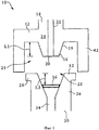
Фиг.1 - вид в разрезе охватываемого коннектора и охватывающего коннектора по первому варианту выполнения устройства в несоединенном состоянии;Figure 1 is a view in section of a male connector and female connector according to the first embodiment of the device in an unconnected state;
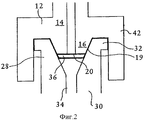
фиг.2 - вид в разрезе охватываемого коннектора и охватывающего коннектора устройства по фиг.1 в соединенном состоянии;figure 2 is a view in section of a male connector and female connector of the device of figure 1 in a connected state;
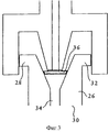
фиг.3 - вид в разрезе охватывающего коннектора устройства по фиг.1 и стандартного охватываемого коннектора Люэра;figure 3 is a sectional view of the female connector of the device of figure 1 and the standard male Luer connector;
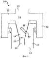
фиг.4 - вид в разрезе охватываемого коннектора и охватывающего коннектора по другому варианту выполнения устройства в несоединенном состоянии;4 is a sectional view of a male connector and female connector according to another embodiment of the device in an unconnected state;
фиг.5 - вид в разрезе охватываемого коннектора и охватывающего коннектора устройства по фиг.4 в частично соединенном состоянии;5 is a sectional view of the male connector and female connector of the device of FIG. 4 in a partially connected state;
фиг.6 - вид в разрезе охватываемого коннектора и охватывающего коннектора устройства по фиг.4 в соединенном состоянии;FIG. 6 is a sectional view of the male connector and female connector of the device of FIG. 4 in a connected state; FIG.
фиг.7 - увеличенный частичный перспективный вид паза и штифта устройства по фиг.4 в частично соединенном состоянии;Fig.7 is an enlarged partial perspective view of the groove and pin of the device of Fig.4 in a partially connected state;
фиг.8 - перспективный вид охватываемого коннектора и охватывающего коннектора устройства;Fig. 8 is a perspective view of a male connector and female device connector;
фиг.9 - вид сбоку фиг.8;Fig.9 is a side view of Fig.8;
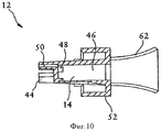
фиг.10 - вид в разрезе фиг.9;figure 10 is a view in section of figure 9;
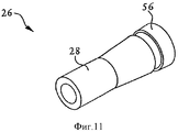
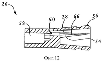
фиг.11 - перспективный вид охватывающего коннектора устройства из фиг.8; фиг.12 - вид в разрезе фиг.12;11 is a perspective view of the female connector of the device of FIG. 12 is a sectional view of FIG. 12;
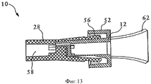
фиг.13 - вид в разрезе охватываемого и охватывающего коннекторов по фиг.8 и 11 в соединенном состоянии;Fig. 13 is a sectional view of the male and female connectors of Figs. 8 and 11 in a connected state;
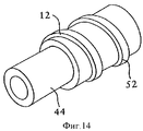
фиг.14 - перспективный вид охватываемого коннектора по другому варианту выполнения устройства;Fig is a perspective view of a male connector according to another embodiment of the device;
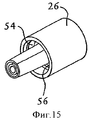
фиг.15 - перспективный вид охватывающего коннектора устройства по фиг.14; иFig - perspective view of the female connector of the device of Fig; and
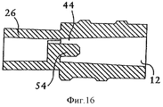
фиг.16 - вид в разрезе охватываемого и охватывающего коннекторов по фиг.14 и 15 в соединенном состоянии.FIG. 16 is a sectional view of the male and female connectors of FIGS. 14 and 15 in a connected state.
Предполагается, что описанный здесь объект изобретения может быть осуществлен во многих формах. Соответственно, варианты выполнения, подробно описанные ниже, к настоящему времени являются предпочтительными вариантами выполнения и не должны рассматриваться как ограничения.It is contemplated that the subject matter described herein may be practiced in many forms. Accordingly, the embodiments described in detail below are currently preferred embodiments and should not be construed as limitations.
Раскрытые варианты выполнения касаются проблем, относящихся к неправильному соединению охватываемого и охватывающего коннектоов Люэра, и губительным последствиям, которые могут вызвать неправильные соединения при критических ситуациях. Раскрытые варианты выполнения решают эти проблемы, по меньшей мере, частично, предлагая устройство, содержащее охватываемый коннектор, который включает в себя корпус с удаленным концом и ближним концом и выступ от корпуса, имеющий отверстие, расположенное на удаленном конце выступа. Отверстие находится в жидкостной связи с каналом для жидкости, расположенным в корпусе. Выступ имеет длину L1. Устройство, кроме того, содержит охватывающий коннектор, содержащий корпус, удаленный конец и ближний конец, канал для жидкости расположенный в корпусе, и элемент, перпендикулярный каналу для жидкости в корпусе. Элемент расположен на длине L2 от ближнего конца охватывающего коннектора и препятствует вставлению выступа за элементом, при этом длина L1 приблизительно равна L2, так что только охватываемый коннектор с выступом, имеющим длину L1, можно полностью вставить в охватывающий коннектор. Это будет препятствовать вставлению стандартных охватываемых коннекторов.The disclosed embodiments relate to problems related to improper connection of male and female Luer connectors, and the disastrous consequences that may cause incorrect connections in critical situations. The disclosed embodiments solve these problems, at least in part, by providing a device comprising a male connector that includes a housing with a distal end and a proximal end and a protrusion from the housing having an opening located at a distal end of the protrusion. The hole is in fluid communication with the fluid channel located in the housing. The protrusion has a length L1. The device further comprises a female connector comprising a housing, a distal end and a proximal end, a fluid channel located in the housing, and an element perpendicular to the fluid channel in the housing. The element is located at a length L2 from the proximal end of the female connector and prevents insertion of the protrusion behind the element, while the length L1 is approximately equal to L2, so that only a male connector with a protrusion having a length L1 can be fully inserted into the female connector. This will prevent the insertion of standard male connectors.
Проблемы также рассматриваются в раскрытых вариантах выполнения, которые предлагают устройство, содержащее охватываемый коннектор, включающий в себя выступ с пазом. Устройство также включает в себя охватывающий коннектор, содержащий штифт, перпендикулярный каналу для жидкости в корпусе. Штифт выполнен так, чтобы входить в зацепление с соответствующим пазом выступа во время вставления охватываемого коннектора в охватывающий коннектор и препятствовать вставлению выступа охватываемого коннектора без паза в охватывающий коннектор устройства, содержащего охватываемый коннектор, включающий в себя паз. Устройство также включает в себя охватывающий коннектор, содержащий штифт. Штифт выполнен так, чтобы входить в зацепление с соответствующим пазом охватываемого коннектора. Штифт расположен так, чтобы обеспечивать только полное вставление специально предназначенного охватываемого коннектора в охватывающий коннектор.Problems are also addressed in the disclosed embodiments that provide a device comprising a male connector including a protrusion with a groove. The device also includes a female connector comprising a pin perpendicular to the fluid channel in the housing. The pin is designed to engage with the corresponding groove of the protrusion during insertion of the male connector into the female connector and to prevent the protrusion of the male connector without groove from being inserted into the female connector of the device containing the male connector including the groove. The device also includes a female connector containing a pin. The pin is designed to engage with the corresponding groove of the male connector. The pin is positioned to only fully insert the specially designed male connector into the female connector.
Другие раскрытые варианты выполнения предлагают устройство, содержащее охватываемый коннектор, который включает в себя корпус, по меньшей мере, с одним зубцом. Охватываемый коннектор, кроме того, включает в себя полость для системы трубок с отклонителями. Отклонители выполнены таким образом, чтобы обеспечивать протекание жидкости через удаленный от центра проход полости для системы трубок. Охватываемый коннектор также включает в себя, по меньшей мере, один компонент крепления. Устройство также содержит охватывающий коннектор, включающий в себя корпус, по меньшей мере, с одной канавкой. Канавка соответствует зубцу охватываемого коннектора и выравнивает охватываемый коннектор при его вставлении в охватывающий коннектор. Охватывающий коннектор включает в себя край, который взаимодействует с компонентом крепления охватываемого коннектора для его крепления в охватывающем коннекторе. Охватывающий коннектор, кроме того, включает в себя полость для системы трубок с отклонителями.Other disclosed embodiments provide a device comprising a male connector that includes a housing with at least one prong. The male connector also includes a cavity for a tube system with deflectors. The diverters are designed in such a way as to allow fluid to flow through a cavity passageway remote from the center for the tube system. The male connector also includes at least one mounting component. The device also comprises a female connector including a housing with at least one groove. The groove corresponds to the tooth of the male connector and aligns the male connector when it is inserted into the female connector. The female connector includes an edge that cooperates with a fastening component of the male connector for mounting it in the female connector. The female connector also includes a cavity for a tube system with deflectors.
Фиг.1 показывает устройство 10. Устройство содержит охватываемый коннектор 12, который включает в себя корпус 14. Корпус 14 имеет удаленный конец 16 и ближний конец 18. Следует отметить, что термин «удаленный» относится к направлению к пациенту. Термин «ближний» относится к направлению от пациента или к шприцу или другому устройству сбора проб или дозирования, например, пакету, для внутривенного вливания. Охватываемый коннектор 12 имеет, в общем, чашеобразную конструкцию, как показано на фиг.1, с полостью 21, выполненной так, чтобы сопрягаться с охватывающим коннектором. Выступ 19 продолжается в полости 21 к удаленному концу 16 корпуса 14. Выступ 19 расположен внутри сопрягаемого участка охватывающего коннектора, как будет описано далее. Выступ 19 включает в себя отверстие 20, находящееся в жидкостной связи с каналом 22 для жидкости. Таким образом, жидкость может беспрепятственно протекать через канал 22 для жидкости и вытекать из отверстия 20.1 shows a
Охватываемый коннектор 12 выполнен так, чтобы плотно сопрягаться с охватывающим коннектором 26, показанным на фиг.1. при этом охватывающий коннектор не может плотно сопрягаться с другими охватываемыми коннекторами. Как показано на фиг.1, устройство 10, кроме того, содержит охватывающий коннектор 26. Охватывающий коннектор 26 включает в себя корпус 28. Корпус 28 имеет удаленный конец 30 и ближний конец 32. Канал 34 для жидкости расположен в корпусе 28. Охватываемый коннектор 12 из фиг.1 может быть вставлен в охватывающий коннектор 26 так, что бы каналы 22, 34 для жидкости были сцентрированы друг с другом. Каналы 22, 34 для жидкости имеют такие размеры, чтобы в них можно было поместить систему для внутривенных инфузий стандартных размеров. Однако другие типы охватываемых коннекторов не могут быть полностью вставлены в охватывающий коннектор 26.The
Охватывающий коннектор 26 включает в себя элемент 36. Элемент 36 расположен неподвижно перпендикулярно каналу 34 для жидкости охватывающего коннектора 26. Элемент 36 расположен неглубоко, так что он не находится непосредственно рядом с удаленным концом 30 охватывающего коннектора 26. Элемент 36 расположен внутри канала 34 для жидкости, так что только специально предназначенный охватываемый коннектор 12 может быть полностью вставлен в охватывающий коннектор 26, как показано на фиг.2. Длина L1 выступа 19, по существу, равна длине L2 между ближним отверстием 23 охватывающего коннектора 26 и элементом 36. Стандартный охватываемый коннектор включает в себя выступы, которые являются более длинными, так чтобы выступы продолжались до удаленного конца охватываемого коннектора.The
Фиг.3 показывает попытку вставить стандартный охватываемый коннектор Люэра в охватывающий коннектор 26. При вставлении ненадлежащего охватываемого коннектора в охватывающий коннектор 26 элемент 36 будет препятствовать надлежащему сопряжению коннекторов 12, 26. В отличие от этого, при использовании коннекторов по фиг.2 со специально предназначенными охватываемым коннектором 12 и охватывающим коннектором 26 может быть образовано герметичное уплотнение после соединения охватываемого и охватывающего коннекторов 12, 26. Элемент 36 не позволяет полностью вставить ненадлежащий охватываемый коннектор, что могло бы привести к потенциально опасной ситуации для пациента со смертельным исходом.Figure 3 shows an attempt to insert a standard male Luer connector into
В некоторых вариантах выполнения охватываемый коннектор 12 включает в себя резьбовую стопорную втулку 42 и корпус 28 охватывающего коннектора 26, который также имеет резьбу. Таким образом, стопорная втулка 42 может быть навинчена вокруг корпуса 26 охватывающего коннектора, скрепляя охватываемый и охватывающий коннекторы 12, 26.In some embodiments,
Как описано выше, элемент 36 охватывающего коннектора 26 препятствует вставлению ненадлежащего охватываемого коннектора 12. Кроме того, охватывающий коннектор 26 визуально не имеет стандартных стопорных втулок, которые встречаются на стандартных охватывающих коннекторах. Это должно служить дополнительным указанием на то, что раскрытый охватывающий коннектор 26 не должен использоваться со стандартными охватываемыми коннекторами Люэра.As described above, the
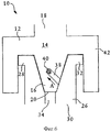
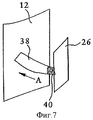
В некоторых других вариантах выполнения, как показано на фиг.4-7, охватываемый коннектор 12 включает в себя паз 38. Паз 38 может быть вырезан с поворачиванием вокруг наружной стороны корпуса 14 охватываемого коннектора 12. Как показано на фиг.4-7, охватывающий коннектор 26 включает в себя штифт 40, который может иметь цилиндрическую форму или может иметь другие формы, выполненные для взаимодействия с пазом. Штифт 40 выполнен для зацепления с пазом 38 охватываемого коннектора 12 при его вставлении в охватывающий коннектор 26.In some other embodiments, as shown in FIGS. 4-7, the
Как показано на фиг.5-7, поскольку охватываемый коннектор 12 вставляют в охватывающий коннектор 26, штифт 40 входит в зацепление с концом паза 38. Штифт 40 расположен неглубоко на охватывающем коннекторе 26. Положение штифта 40 препятствует полному вставлению и зацеплению стандартного охватываемого коннектора Люэра. Положение штифта 40 таково, что он входит в зацепление с пазом 38, когда охватываемый коннектор 12 вставлен только частично, как показано на фиг.5. Охватываемый коннектор 12 затем поворачивают, когда его полностью вставляют в охватывающий коннектор 26, так что штифт 40 перемещается вверх и далее в паз 38 в направлении А, как показано на фиг.6 и 7.As shown in FIGS. 5-7, since the
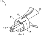
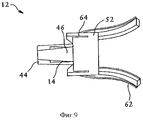
Фиг.8-10 показывают устройство 10, содержащее охватываемый коннектор 12, в котором корпус 14 имеет, по меньшей мере, один зубец 44. Как показано на фиг.8, охватываемый коннектор 12 включает в себя полость 46 для системы трубок с отклонителями 48. Отклонители 48 выполнены таким образом, чтобы обеспечивать протекание жидкости через охватываемый коннектор 12 и протекать через удаленный от центра проход 50 полости 46 для системы трубок. Таким образом, жидкость будет иметь более прямой проход через охватываемый коннектор 12. Охватываемый коннектор 12, кроме того, включает в себя, по меньшей мере, один элемент 52 крепления. Элемент 52 крепления может быть защелкивающимся элементом 52 защелкивающегося коннекторы.Figs. 8-10 show a
Устройство 10, кроме того, включает в себя охватывающий коннектор 26, показанный на фиг.11 - 12, в котором охватывающий коннектор 26 включает в себя, по меньшей мере, одну канавку 54 (фиг.12). Канавка 54 образована между некоторым количеством ребер 66, расположенных в охватывающем коннекторе 26. Канавка 54 соответствует зубцу 44 охватываемого соединителя 12. При вставлении охватываемого коннектора 12 в охватывающий коннектор 26 канавка 54 и зубец 44 при сопряжении входят в зацепление, выравнивая охватываемый коннектор 12 внутри охватывающего коннектора 26, как показано на фиг 13. Канавка 54 сходит на конус, так что зубец 44 будет более легко выравниваться по канавке 54. Охватываемый коннектор 12 может поворачиваться до тех пор, пока зубец 44 не войдет в зацепление с канавкой 54. Несмотря на то, что может быть показан только один зубец 44, предполагается, что охватываемый коннектор 12 содержит некоторое количество зубцов 44, которые входят в зацепление с некоторым количеством соответствующих канавок 54. Наличие зубца 44 и канавки 54 препятствует совместимости устройства 10 со стандартными охватываемыми и охватывающими коннекторами Люэра по ISO. Таким образом, устройство обеспечивает условия, при которых ненадлежащий коннектор и линия не будут подключены к пациенту.The
Охватывающий коннектор 26 также включает в себя край 56, показанный на фиг.11 и 12. Край 56 взаимодействует с защелкивающимся элементом 52 охватываемого коннектора 12, как показано на фиг.8. Таким образом, как показано на фиг.13, для коннекторы охватываемого и охватывающего коннекторов 12, 26 защелкивающийся элемент 52 защелкивается на краю 56. Это позволяет соединить коннекторы 12, 26 и может образовать герметичное уплотнение. Корпусы 14, 28 охватываемого и охватывающего коннекторов 12, 26, в общем, имеют цилиндрическую форму, так что они могут легко сопрягаться. Однако корпусы 14, 28 также могут иметь другую геометрию формы.The
Как показано на фиг.12, охватывающий коннектор 26, кроме того, включает в себя полость 58 для системы трубок с отклонителями 60. Полости 46, 58 для системы трубок имеют такие размеры, чтобы в них можно было разместить систему для внутривенных инфузий стандартных размеров. Отклонители 48, 60 защищают систему в полостях 46, 58 для системы трубок от образования уплотнения у основания полости для системы трубок. Это препятствует протеканию жидкости через устройство 10 и к пациенту или приемнику жидкости.As shown in FIG. 12,
Охватываемый коннектор 12 также может включать в себя, по меньшей мере, одно крыло 62 и корпус 14 может иметь прорезь 64. Крыло 62 имеет такую форму, чтобы продолжаться наружу от корпуса 14, как показано на фиг.8-10. Прорезь 64 предназначена для независимой гибкости крыла 62. Сжатие крыла 63 выводит его из зацепления с защелкивающимся элементом 52 охватываемого коннектора 12. Прорезь 64 позволяет крылу свободно изгибаться и отходить от корпуса 14 охватываемого коннектора 12. Это обеспечивает удаление охватываемого коннектора 12 из охватывающего коннектора 26. Предполагается, что охватываемый коннектор 12 может включать в себя некоторое количество крыльев 62.The
Элемент 52 крепления охватываемого коннектора 12 может иметь резьбу и край 56 охватывающего коннектора 26 может иметь резьбу. Таким образом, для коннекторы охватываемого и охватывающего коннекторов 12, 26 охватываемый коннектор 12 может быть навинчен на охватывающий коннектор 26.The
В другом варианте выполнения, показанном на фиг.14-16, зубец 44 охватываемого коннектора 12 может быть кольцевым. Зубец 44, показанный на фиг.16, может быть полым внутри своей окружности, так чтобы он все же мог входить в зацепление с канавкой 54 охватывающего коннектора 26. Канавка 54 охватывающего коннектора 26, показанная на фиг.15, также может иметь кольцевую форму, чтобы в ней мог поместиться зубец 44 охватываемого коннектора 12. Кроме того, как показано на фиг.14-15, элемент 52 крепления охватываемого коннектора 12 может иметь резьбу и край 56 охватывающего коннектора 25 может иметь резьбу. Таким образом, для соединения охватываемого и охватывающего коннекторов 12, 26 охватываемый коннектор 12 может быть навинчен на охватывающий коннектор 26, как показано на фиг.16.In another embodiment, shown in Fig.14-16, the
В общем, предлагается устройство, имеющее охватываемый коннектор. Охватывающий коннектор будет принимать только специально предназначенный охватываемый коннектор, таким образом, препятствуя неправильному соединению с ненадлежащим охватываемым коннектором. В некоторых вариантах выполнения элемент препятствует полному вставлению в охватывающий коннектор охватываемых коннекторов, не относящихся к специально предназначенному охватываемому коннектору. В некоторых других вариантах выполнения штифт препятствует полному вставлению в охватывающий коннектор охватываемых коннекторов Люэра, не относящихся к специально предназначенному охватываемому коннектору, включающему в себя паз. Кроме того, в некоторых других вариантах выполнения группа зубцов в охватываемом коннекторе и соответствующие канавки в охватывающем коннекторе обеспечивают надлежащее соединение. После вставления охватываемого коннектора и его крепления в охватывающем коннекторе, образуется герметичное уплотнение между охватываемым коннектором и охватывающим коннектором. Раскрытые варианты выполнения, таким образом, предотвращают неправильное соединение охватываемых и охватывающих коннекторов Люэра без необходимости для медицинского персонала выполнять дополнительные предупредительные действия.In general, a device having a male connector is provided. The female connector will only accept a specially designed male connector, thus preventing improper connection with an improper male connector. In some embodiments, the element prevents the male connectors from being fully inserted into the female connector, not related to the specially designed male connector. In some other embodiments, the pin prevents full insertion into the female connector of male Luer connectors that are not related to the specially designed male connector, including a groove. In addition, in some other embodiments, the group of teeth in the male connector and the corresponding grooves in the female connector provide the proper connection. After the male connector is inserted and secured in the female connector, a tight seal is formed between the male connector and the female connector. The disclosed embodiments thus prevent improper connection of male and female Luer connectors without the need for additional preventative actions by medical personnel.
Несмотря на то, что раскрытые варианты выполнения были подробно описаны и проиллюстрированы, должно быть понятно, что они приведены только в качестве пояснения и примера и не должны считаться ограничением.Although the disclosed embodiments have been described in detail and illustrated, it should be understood that they are provided only as an explanation and example and should not be considered a limitation.
Claims (32)
охватываемый коннектор, имеющий корпус с удаленным концом и ближним концом и выступ от корпуса, имеющий наружную коническую поверхность с конусом Люэра и отверстие, расположенное на удаленном конце выступа и находящееся в жидкостной связи с каналом для жидкости, расположенным в корпусе охватываемого коннектора, при этом выступ имеет длину L1; и
охватывающий коннектор, имеющий корпус с удаленным концом и ближним концом и внутренний канал для жидкости, имеющий внутреннюю коническую поверхность с конусом Люэра, предназначенным для герметичного сопряжения с внутренней конической поверхностью охватываемого коннектора, и элемент, выступающий во внутренний канал для жидкости от внутренней конической поверхности; элемент расположен на длине L2 от ближнего конца охватывающего коннектора и препятствует вставлению выступа за элемент при L1=L2, так что наружная коническая поверхность охватываемого коннектора Люэра с выступом, имеющим длину, превышающую длину L1, не может герметично сопрягаться с внутренней конической поверхностью охватывающего коннектора.1. A connector containing
male connector having a housing with a remote end and a proximal end and a protrusion from the body, having an outer conical surface with a Luer cone and an opening located at the remote end of the protrusion and in fluid communication with a fluid channel located in the housing of the male connector, the protrusion has a length of L1; and
a female connector having a housing with a distal end and a proximal end and an internal fluid channel having an inner conical surface with a Luer cone for tightly mating with the inner conical surface of the male connector, and an element protruding into the inner fluid channel from the inner conical surface; the element is located at a length L2 from the proximal end of the female connector and prevents the protrusion from pasting the element at L1 = L2, so that the outer conical surface of the male Luer connector with a protrusion having a length exceeding the length L1 cannot hermetically mate with the inner conical surface of the female connector.
охватываемый коннектор, содержащий корпус с резьбовой стопорной втулкой, дальний конец, ближний конец и выступ с наружной конической поверхностью с конусом Люэра и отверстием, расположенным у дальнего конца выступа; отверстие находится в жидкостной связи с каналом для жидкости, расположенным в корпусе, при этом выступ имеет паз, и
охватывающий коннектор, содержащий корпус, дальний конец и ближний конец и канал для жидкости, расположенный в корпусе, имеющем внутреннюю коническую поверхность с конусом Люэра, предназначенным для герметичного сопряжения с наружной конической поверхностью охватываемого коннектора; охватывающий коннектор дополнительно содержит штифт, выступающий в канал для жидкости охватывающего коннектора в переходной точке ближнего конца и дальнего конца внутренней конической поверхности; штифт предназначен для зацепления с пазом выступа во время вставления охватываемого коннектора в охватывающий коннектор, в котором наружная коническая поверхность охватываемого коннектора Люэра без паза не может герметично сопрягаться с внутренней конической поверхностью охватывающего коннектора.3. A connector containing
a male connector comprising a housing with a threaded locking sleeve, a distal end, a proximal end and a protrusion with an outer conical surface with a Luer cone and an opening located at the far end of the protrusion; the hole is in fluid communication with the fluid channel located in the housing, while the protrusion has a groove, and
a female connector comprising a housing, a distal end and a proximal end and a fluid channel located in a housing having an inner conical surface with a Luer cone for tightly mating with the outer conical surface of the male connector; the female connector further comprises a pin protruding into the fluid channel of the female connector at a transition point of the proximal end and the distal end of the inner conical surface; the pin is designed to engage with the groove of the protrusion during insertion of the male connector into the female connector, in which the outer conical surface of the male Luer connector without a groove cannot hermetically mate with the inner conical surface of the female connector.
охватываемый коннектор, имеющий корпус с удаленным концом и ближним концом, отверстие, расположенное на дальнем конце корпуса, находящееся в жидкостной связи с каналом для жидкости, расположенным в корпусе; при этом охватываемый коннектор включает в себя выступ с пазом; и
охватывающий коннектор, содержащий корпус с удаленным концом и ближним концом, канал для жидкости, расположенный в корпусе; при этом охватывающий коннектор содержит штифт, перпендикулярный каналу для жидкости в корпусе, входящий в зацепление с пазом выступа во время вставления охватываемого коннектора в охватывающий коннектор.4. A connector containing
a male connector having a housing with a distal end and a proximal end, an opening located at a distal end of the housing, in fluid communication with a fluid channel located in the housing; wherein the male connector includes a protrusion with a groove; and
a female connector comprising a housing with a distal end and a proximal end; a fluid channel located in the housing; wherein the female connector comprises a pin perpendicular to the fluid channel in the housing, engaged with a groove of the protrusion during insertion of the male connector into the female connector.
охватываемый коннектор, имеющий корпус, по меньшей мере, с одним зубцом и полость для системы трубок с отклонителями, выполненными с возможностью протекания жидкости через удаленный от центра проход полости для системы трубок; при этом охватываемый коннектор включает в себя, по меньшей мере, один элемент крепления;
и охватывающий коннектор, имеющий корпус, по меньшей мере, с одной канавкой, соответствующей зубцу охватываемого коннектора и выравнивающей охватываемый коннектор при его вставлении в охватывающий коннектор; охватывающий коннектор включает в себя край, взаимодействующий с элементом крепления охватываемого коннектора для крепления охватываемого коннектора в охватывающем коннекторе; при этом охватывающий коннектор включает в себя полость для системы трубок с отклонителями.11. A connector containing
a male connector having a body with at least one tooth and a cavity for a tube system with deflectors configured to allow fluid to flow through a cavity of the tube system that is remote from the center; wherein the male connector includes at least one fastener;
and a female connector having a housing with at least one groove corresponding to a tooth of the male connector and aligning the male connector when it is inserted into the female connector; the female connector includes an edge cooperating with a male connector fastener for attaching a male connector in the female connector; wherein the female connector includes a cavity for a tube system with deflectors.
охватываемый коннектор, содержащий корпус с множеством зубцов, предназначенных для совместного образования выступа из корпуса с внешней конической поверхностью с конусом Люэра с пазами, отделяющими зубцы, по меньшей мере, для участка длины выступа, при этом каждый зубец связи с каналом для жидкости, расположенным в корпусе охватываемого коннектора; и
охватывающий коннектор, содержащий корпус с полостью, имеющей внутреннюю коническую поверхность, имеющую конус Люэра с множеством канавок во внутренней конической поверхности, соответствующих зубцам охватываемого коннектора, при этом каждая канавка связана с каналом для жидкости, расположенным в корпусе охватывающего коннектора; канавки разделены ребрами, которые вставлены в пазы охватываемого коннектора, когда охватываемый коннектор сопрягается с охватывающим коннектором, так что наружная коническая поверхность охватываемого коннектора Люэра без зубцов не может герметично сопрягаться с внутренней конической поверхностью охватывающего коннектора.23. A connector containing
a male connector comprising a housing with a plurality of teeth intended for jointly forming a protrusion from the housing with an external conical surface with a Luer cone with grooves separating the teeth, at least for a portion of the length of the protrusion, each tooth linking to a fluid channel located in the housing of the male connector; and
a female connector comprising a body with a cavity having an internal conical surface having a Luer cone with a plurality of grooves in the internal conical surface corresponding to the teeth of the male connector, wherein each groove is associated with a fluid channel located in the body of the female connector; the grooves are separated by ribs that are inserted into the grooves of the male connector when the male connector mates with the female connector, so that the outer conical surface of the male Luer connector without teeth cannot hermetically mate with the inner conical surface of the female connector.
охватываемый коннектор с дальним концом и ближним концом, содержащий первую полость для трубок, предназначенную для размещения трубки, и несколько зубцов, каждый из которых имеет отверстие у дальнего конца, связанное с первой полостью для трубок, и
охватывающий коннектор с дальним концом и ближним концом, содержащий вторую полость для трубок, предназначенную для размещения трубки, и полость, содержащую несколько канавок, предназначенную для зацепления с несколькими зубцами охватываемого коннектора.24. A connector containing
a male connector with a distal end and a proximal end, comprising a first tube cavity for receiving the tube, and several teeth, each of which has a hole at the far end associated with the first tube cavity, and
a female connector with a distal end and a proximal end, comprising a second tube cavity for receiving the tube, and a cavity containing several grooves for engaging with several teeth of the male connector.
Applications Claiming Priority (3)
| Application Number | Priority Date | Filing Date | Title |
|---|---|---|---|
| US11/765,894 | 2007-06-20 | ||
| US11/765,894 US8070189B2 (en) | 2007-06-20 | 2007-06-20 | Safety luer connection |
| PCT/US2008/067734 WO2008157788A2 (en) | 2007-06-20 | 2008-06-20 | Safety luer connection |
Publications (2)
| Publication Number | Publication Date |
|---|---|
| RU2010101617A RU2010101617A (en) | 2011-07-27 |
| RU2493888C2 true RU2493888C2 (en) | 2013-09-27 |
Family
ID=39672995
Family Applications (1)
| Application Number | Title | Priority Date | Filing Date |
|---|---|---|---|
| RU2010101617/14A RU2493888C2 (en) | 2007-06-20 | 2008-06-20 | Safe luer connector |
Country Status (11)
| Country | Link |
|---|---|
| US (3) | US8070189B2 (en) |
| EP (1) | EP2170453B1 (en) |
| JP (2) | JP5406832B2 (en) |
| CN (3) | CN102512755A (en) |
| AU (1) | AU2008265597B2 (en) |
| BR (2) | BRPI0812861B8 (en) |
| CA (1) | CA2691182C (en) |
| ES (1) | ES2960903T3 (en) |
| RU (1) | RU2493888C2 (en) |
| WO (1) | WO2008157788A2 (en) |
| ZA (1) | ZA200908903B (en) |
Families Citing this family (38)
| Publication number | Priority date | Publication date | Assignee | Title |
|---|---|---|---|---|
| US6695817B1 (en) | 2000-07-11 | 2004-02-24 | Icu Medical, Inc. | Medical valve with positive flow characteristics |
| AU2005304987B2 (en) | 2004-11-05 | 2011-08-11 | Icu Medical, Inc. | Medical connector having high flow rate characteristics |
| US8414554B2 (en) | 2008-05-14 | 2013-04-09 | J & J Solutions, Inc. | Systems and methods for safe medicament transport |
| EP2140905B1 (en) * | 2008-06-30 | 2011-08-17 | Tyco Healthcare Group LP | Discriminating Oral Tip Adaptor |
| US8454579B2 (en) | 2009-03-25 | 2013-06-04 | Icu Medical, Inc. | Medical connector with automatic valves and volume regulator |
| US8684979B2 (en) * | 2009-05-11 | 2014-04-01 | Covidien Lp | Discriminating fluid connection system |
| US8950789B2 (en) | 2009-12-18 | 2015-02-10 | Rain Bird Corporation | Barbed connection for use with irrigation tubing |
| US8567696B2 (en) | 2009-12-18 | 2013-10-29 | Rain Bird Corporation | Nozzle body for use with irrigation devices |
| US9205248B2 (en) * | 2010-02-24 | 2015-12-08 | Becton, Dickinson And Company | Safety Drug delivery connectors |
| US9056163B2 (en) * | 2010-02-24 | 2015-06-16 | Becton, Dickinson And Company | Safety drug delivery system |
| USD644731S1 (en) | 2010-03-23 | 2011-09-06 | Icu Medical, Inc. | Medical connector |
| US8758306B2 (en) | 2010-05-17 | 2014-06-24 | Icu Medical, Inc. | Medical connectors and methods of use |
| AU2011258371B2 (en) | 2010-05-27 | 2014-09-18 | J&J Solutions, Inc. | Closed fluid transfer system |
| US8465461B2 (en) | 2010-07-27 | 2013-06-18 | Becton, Dickinson And Company | Blunt needle safety drug delivery system |
| DE102011011762B4 (en) * | 2011-02-18 | 2019-02-21 | Geuder Aktiengesellschaft | Luer connection as a connection system for medical cables |
| US20130079754A1 (en) * | 2011-09-26 | 2013-03-28 | General Electric Company | Connection system |
| WO2014033793A1 (en) * | 2012-08-31 | 2014-03-06 | テルモ株式会社 | Connector, and tube connection structure using same |
| US10207096B2 (en) | 2013-02-27 | 2019-02-19 | Fresenius Medical Care Holdings, Inc. | Fluid line connectors |
| US20160030729A1 (en) * | 2013-03-12 | 2016-02-04 | Ultradent Products, Inc. | Luer connector |
| US20140290061A1 (en) * | 2013-03-28 | 2014-10-02 | Uop Llc | Apparatus for a Radial-Flow Reactor and Method for Assembly Thereof |
| US20140290062A1 (en) * | 2013-03-28 | 2014-10-02 | Uop Llc | Apparatus for a Radial-Flow Reactor and Method for Assembly Thereof |
| MX371346B (en) | 2013-08-02 | 2020-01-27 | J&J Solutions Inc D/B/A Corvida Medical | Compounding systems and methods for safe medicament transport. |
| DE102013018639A1 (en) | 2013-11-06 | 2014-07-24 | Fresenius Medical Care Deutschland Gmbh | Connector for connecting bag and hose system for providing e.g. medical solution during extraporal blood treatment for patient, has cone only opening sealing element when projection of one part is inserted in retainer of other part |
| CA2932124C (en) | 2013-12-11 | 2023-05-09 | Icu Medical, Inc. | Check valve |
| USD786427S1 (en) | 2014-12-03 | 2017-05-09 | Icu Medical, Inc. | Fluid manifold |
| USD793551S1 (en) | 2014-12-03 | 2017-08-01 | Icu Medical, Inc. | Fluid manifold |
| CN104491982B (en) * | 2014-12-31 | 2017-04-12 | 郑州迪奥医学技术有限公司 | Safe high-flow drainage connecting tube |
| AU2016256176B2 (en) * | 2015-04-30 | 2020-12-24 | Gambro Lundia Ab | A male fluid connector, a female fluid connector and a fluid connection system comprising the same |
| US10888496B2 (en) | 2015-09-17 | 2021-01-12 | Corvida Medical, Inc. | Medicament vial assembly |
| US10894317B2 (en) | 2015-10-13 | 2021-01-19 | Corvida Medical, Inc. | Automated compounding equipment for closed fluid transfer system |
| WO2018030354A1 (en) * | 2016-08-09 | 2018-02-15 | 日機装株式会社 | Blood circuit adapter set and blood circuit |
| EP3583965B1 (en) | 2016-08-09 | 2024-01-24 | Nikkiso Co., Ltd. | Blood purification device configured for priming purposes |
| US11272946B2 (en) * | 2018-03-09 | 2022-03-15 | Acclarent, Inc. | Fluid fitting for dilation instrument |
| CN108853691A (en) * | 2018-05-15 | 2018-11-23 | 因诺唯特(武汉)科技有限公司 | A kind of central venous catheter |
| CN110364857A (en) * | 2019-07-18 | 2019-10-22 | 内蒙古电力(集团)有限责任公司乌海电业局 | A kind of 0.4kV low-voltage cable transition joint attachment device |
| US11472691B2 (en) * | 2020-02-21 | 2022-10-18 | Timothy Ohara | Assembly for providing a passageway for a beverage line connected between a beverage vessel contained in a cabinet, and a beverage tap secured to a tabletop accessory |
| CN111805142B (en) * | 2020-07-14 | 2021-11-23 | 南京佩尔哲汽车内饰系统有限公司 | Pressing mechanism with pressure head structure capable of being replaced quickly |
| CN112984240B (en) * | 2021-04-07 | 2024-08-16 | 宏岳塑胶集团股份有限公司 | Quick-inserting pipe fitting |
Citations (7)
| Publication number | Priority date | Publication date | Assignee | Title |
|---|---|---|---|---|
| DE29818311U1 (en) * | 1998-10-13 | 1999-01-28 | Noebel, Eberhard, 34497 Korbach | Connector for medical infusion systems |
| GB2356148A (en) * | 1999-11-09 | 2001-05-16 | Kci Medical Ltd | Wound drainage apparatus |
| RU2180600C2 (en) * | 1995-06-07 | 2002-03-20 | Айку Медикал, Инк. | Medical connector |
| US6422607B1 (en) * | 1998-06-01 | 2002-07-23 | Micron Technology, Inc. | Ramp-lock fitting device |
| RU2197285C2 (en) * | 1996-11-26 | 2003-01-27 | Бакстер Интернэшнл Инк. | Multilumen device for making surgical access |
| WO2007047845A2 (en) * | 2005-10-20 | 2007-04-26 | Richmond Frank M | Conversion device |
| WO2008049568A1 (en) * | 2006-10-25 | 2008-05-02 | Fresenius Kabi Deutschland Gmbh | Connection piece for an enteral transfer system |
Family Cites Families (35)
| Publication number | Priority date | Publication date | Assignee | Title |
|---|---|---|---|---|
| US803127A (en) * | 1904-08-11 | 1905-10-31 | Charles T Palmer | Hose-coupling. |
| US4116903A (en) * | 1977-03-02 | 1978-09-26 | P.R.A. Laboratories Incorporated | Alkyd-supported emulsion interpolymers and methods for preparation |
| WO1981000053A1 (en) | 1979-07-04 | 1981-01-22 | Travenol Lab Pty Ltd | Sterile fluid line coupling members |
| US4600015A (en) * | 1980-10-28 | 1986-07-15 | Antec Systems Limited | Patient monitoring apparatus and method |
| US4369781A (en) | 1981-02-11 | 1983-01-25 | Sherwood Medical Industries Inc. | Luer connector |
| SE455470B (en) | 1981-06-23 | 1988-07-18 | Terumo Corp | CONNECTING TWO HOSE FOR MEDICAL, THERAPEUTICAL USE HOSE |
| DE3267330D1 (en) * | 1981-12-29 | 1985-12-12 | Akzo Nv | Aqueous, oxidatively drying coating composition |
| US4511359A (en) * | 1982-09-29 | 1985-04-16 | Manresa, Inc. | Sterile connection device |
| US4619640A (en) | 1984-08-17 | 1986-10-28 | Potolsky Abraham I | Blood transfusion connector assembly |
| CA1330285C (en) * | 1987-12-22 | 1994-06-21 | Geoffrey S. Martin | Triple lumen catheter |
| US5964785A (en) * | 1988-01-25 | 1999-10-12 | Baxter International Inc. | Bayonet look cannula for pre-slit y-site |
| ATE127894T1 (en) * | 1990-01-18 | 1995-09-15 | Oneil Alexander G B | FLUID CONNECTOR. |
| US5059170A (en) * | 1990-02-02 | 1991-10-22 | Mallinckrodt Medical, Inc. | Connection adapter for catheters |
| AU646666B2 (en) * | 1990-05-14 | 1994-03-03 | Colin Nates | Surgical apparatus |
| US5603706A (en) * | 1992-09-29 | 1997-02-18 | Wyatt; Philip | Infusion apparatus |
| WO1994023775A1 (en) * | 1993-03-23 | 1994-10-27 | Abbott Laboratories | Securing collar for cannula connector |
| US5624402A (en) * | 1994-12-12 | 1997-04-29 | Becton, Dickinson And Company | Syringe tip cap |
| IT1281248B1 (en) * | 1995-11-16 | 1998-02-17 | Pier Luigi Delvigo | MEDICAL SAFETY DEVICE FOR TRANSFUSIONS. |
| US5810792A (en) * | 1996-04-03 | 1998-09-22 | Icu Medical, Inc. | Locking blunt cannula |
| US5782505A (en) * | 1996-08-29 | 1998-07-21 | Becton, Dickinson And Company | Catheter adapter assembly |
| US6402207B1 (en) | 1997-06-09 | 2002-06-11 | Qd Enterprises, Llc | Safety indexed medical connectors |
| US6651851B2 (en) * | 1999-09-15 | 2003-11-25 | Technical Concepts, Llc | System and method for dispensing soap |
| JP2001299906A (en) | 2000-04-25 | 2001-10-30 | Terumo Corp | Connector assembly |
| US6745998B2 (en) | 2001-08-10 | 2004-06-08 | Alaris Medical Systems, Inc. | Valved male luer |
| DE10140292A1 (en) | 2001-08-16 | 2003-03-06 | Ruesch Willy Gmbh | Connecting element attached to closure element has elliptical ends, with first and second detent elements and pressure elements |
| FR2836832B1 (en) | 2002-03-08 | 2005-02-04 | Optis France Sa | CONNECTION ASSEMBLY FOR MEDICAL USE FOR THE TRANSFER OF FLUIDS |
| AU2002329802B2 (en) * | 2002-08-22 | 2008-01-17 | Cardinal Health 529, Llc | Sliding seal adapter for a feeding system |
| IL152950A0 (en) * | 2002-11-19 | 2003-06-24 | Biometrix Ltd | A fluid administrating manifold |
| US7393339B2 (en) * | 2003-02-21 | 2008-07-01 | C. R. Bard, Inc. | Multi-lumen catheter with separate distal tips |
| US20050090805A1 (en) * | 2003-10-28 | 2005-04-28 | Shaw Scott R. | Reconnectable disconnect device for fluid transfer line |
| FR2863162B1 (en) | 2003-12-05 | 2006-12-08 | Vygon | MALE FITTINGS AND FEMALE FITTINGS FOR REALIZING LIQUID TRANSMISSION CONNECTIONS, IN PARTICULAR FOR ENTERALE NUTRITION LINES |
| JP4621029B2 (en) * | 2004-02-19 | 2011-01-26 | テルモ株式会社 | connector |
| US20070060898A1 (en) | 2005-09-07 | 2007-03-15 | Shaughnessy Michael C | Enteral medical treatment assembly having a safeguard against erroneous connection with an intravascular treatment system |
| DE102005049402A1 (en) * | 2005-10-13 | 2007-04-19 | Basf Ag | Aqueous binder composition |
| GB0604952D0 (en) | 2006-03-13 | 2006-04-19 | Renishaw Plc | A fluid connector for fluid delivery apparatus |
-
2007
- 2007-06-20 US US11/765,894 patent/US8070189B2/en active Active
-
2008
- 2008-06-20 CA CA2691182A patent/CA2691182C/en active Active
- 2008-06-20 CN CN2011104008738A patent/CN102512755A/en active Pending
- 2008-06-20 WO PCT/US2008/067734 patent/WO2008157788A2/en active Application Filing
- 2008-06-20 JP JP2010513458A patent/JP5406832B2/en active Active
- 2008-06-20 ES ES08771634T patent/ES2960903T3/en active Active
- 2008-06-20 AU AU2008265597A patent/AU2008265597B2/en active Active
- 2008-06-20 CN CN2011104008649A patent/CN102430197A/en active Pending
- 2008-06-20 EP EP08771634.6A patent/EP2170453B1/en active Active
- 2008-06-20 RU RU2010101617/14A patent/RU2493888C2/en active
- 2008-06-20 BR BRPI0812861A patent/BRPI0812861B8/en active IP Right Grant
- 2008-06-20 CN CN2008800246146A patent/CN101784301B/en active Active
- 2008-06-20 BR BR122019006499A patent/BR122019006499B8/en active IP Right Grant
-
2009
- 2009-12-14 ZA ZA200908903A patent/ZA200908903B/en unknown
-
2011
- 2011-11-01 US US13/287,043 patent/US9550054B2/en active Active
-
2013
- 2013-04-10 JP JP2013081940A patent/JP5680693B2/en active Active
-
2017
- 2017-01-13 US US15/405,837 patent/US10920915B2/en active Active
Patent Citations (7)
| Publication number | Priority date | Publication date | Assignee | Title |
|---|---|---|---|---|
| RU2180600C2 (en) * | 1995-06-07 | 2002-03-20 | Айку Медикал, Инк. | Medical connector |
| RU2197285C2 (en) * | 1996-11-26 | 2003-01-27 | Бакстер Интернэшнл Инк. | Multilumen device for making surgical access |
| US6422607B1 (en) * | 1998-06-01 | 2002-07-23 | Micron Technology, Inc. | Ramp-lock fitting device |
| DE29818311U1 (en) * | 1998-10-13 | 1999-01-28 | Noebel, Eberhard, 34497 Korbach | Connector for medical infusion systems |
| GB2356148A (en) * | 1999-11-09 | 2001-05-16 | Kci Medical Ltd | Wound drainage apparatus |
| WO2007047845A2 (en) * | 2005-10-20 | 2007-04-26 | Richmond Frank M | Conversion device |
| WO2008049568A1 (en) * | 2006-10-25 | 2008-05-02 | Fresenius Kabi Deutschland Gmbh | Connection piece for an enteral transfer system |
Also Published As
| Publication number | Publication date |
|---|---|
| ES2960903T3 (en) | 2024-03-07 |
| AU2008265597B2 (en) | 2013-05-09 |
| BRPI0812861B8 (en) | 2021-06-22 |
| BR122019006499B8 (en) | 2021-06-22 |
| BRPI0812861B1 (en) | 2019-12-31 |
| US20080318456A1 (en) | 2008-12-25 |
| CN101784301B (en) | 2012-06-13 |
| US10920915B2 (en) | 2021-02-16 |
| US9550054B2 (en) | 2017-01-24 |
| CA2691182A1 (en) | 2008-12-24 |
| RU2010101617A (en) | 2011-07-27 |
| CA2691182C (en) | 2015-02-10 |
| AU2008265597A1 (en) | 2008-12-24 |
| CN101784301A (en) | 2010-07-21 |
| BR122019006499B1 (en) | 2019-12-31 |
| CN102512755A (en) | 2012-06-27 |
| BRPI0812861A2 (en) | 2014-12-09 |
| JP5680693B2 (en) | 2015-03-04 |
| JP2010530789A (en) | 2010-09-16 |
| EP2170453C0 (en) | 2023-10-25 |
| JP5406832B2 (en) | 2014-02-05 |
| EP2170453A2 (en) | 2010-04-07 |
| EP2170453B1 (en) | 2023-10-25 |
| US20170120029A1 (en) | 2017-05-04 |
| US20120046650A1 (en) | 2012-02-23 |
| US8070189B2 (en) | 2011-12-06 |
| CN102430197A (en) | 2012-05-02 |
| WO2008157788A2 (en) | 2008-12-24 |
| ZA200908903B (en) | 2010-09-29 |
| WO2008157788A3 (en) | 2009-04-09 |
| JP2013150868A (en) | 2013-08-08 |
Similar Documents
| Publication | Publication Date | Title |
|---|---|---|
| RU2493888C2 (en) | Safe luer connector | |
| JP4299464B2 (en) | Safely aligned medical connector | |
| EP2251061B1 (en) | Discriminating fluid connection system | |
| US11918796B2 (en) | Syringe adapter with secure connection | |
| CA2872434C (en) | Piercing member protection device | |
| US20210212902A1 (en) | Lockable adapter assembly |