RU2492785C2 - Tool holder - Google Patents
Tool holder Download PDFInfo
- Publication number
- RU2492785C2 RU2492785C2 RU2010137834/12A RU2010137834A RU2492785C2 RU 2492785 C2 RU2492785 C2 RU 2492785C2 RU 2010137834/12 A RU2010137834/12 A RU 2010137834/12A RU 2010137834 A RU2010137834 A RU 2010137834A RU 2492785 C2 RU2492785 C2 RU 2492785C2
- Authority
- RU
- Russia
- Prior art keywords
- tool holder
- section
- wall
- bracket
- combination according
- Prior art date
Links
Images


Classifications
-
- F—MECHANICAL ENGINEERING; LIGHTING; HEATING; WEAPONS; BLASTING
- F16—ENGINEERING ELEMENTS AND UNITS; GENERAL MEASURES FOR PRODUCING AND MAINTAINING EFFECTIVE FUNCTIONING OF MACHINES OR INSTALLATIONS; THERMAL INSULATION IN GENERAL
- F16M—FRAMES, CASINGS OR BEDS OF ENGINES, MACHINES OR APPARATUS, NOT SPECIFIC TO ENGINES, MACHINES OR APPARATUS PROVIDED FOR ELSEWHERE; STANDS; SUPPORTS
- F16M13/00—Other supports for positioning apparatus or articles; Means for steadying hand-held apparatus or articles
- F16M13/02—Other supports for positioning apparatus or articles; Means for steadying hand-held apparatus or articles for supporting on, or attaching to, an object, e.g. tree, gate, window-frame, cycle
-
- A—HUMAN NECESSITIES
- A47—FURNITURE; DOMESTIC ARTICLES OR APPLIANCES; COFFEE MILLS; SPICE MILLS; SUCTION CLEANERS IN GENERAL
- A47F—SPECIAL FURNITURE, FITTINGS, OR ACCESSORIES FOR SHOPS, STOREHOUSES, BARS, RESTAURANTS OR THE LIKE; PAYING COUNTERS
- A47F5/00—Show stands, hangers, or shelves characterised by their constructional features
- A47F5/08—Show stands, hangers, or shelves characterised by their constructional features secured to the wall, ceiling, or the like; Wall-bracket display devices
- A47F5/0807—Display panels, grids or rods used for suspending merchandise or cards supporting articles; Movable brackets therefor
- A47F5/0846—Display panels or rails with elongated channels; Sliders, brackets, shelves, or the like, slidably attached therein
-
- B—PERFORMING OPERATIONS; TRANSPORTING
- B25—HAND TOOLS; PORTABLE POWER-DRIVEN TOOLS; MANIPULATORS
- B25H—WORKSHOP EQUIPMENT, e.g. FOR MARKING-OUT WORK; STORAGE MEANS FOR WORKSHOPS
- B25H3/00—Storage means or arrangements for workshops facilitating access to, or handling of, work tools or instruments
- B25H3/04—Racks
Abstract
Description
Настоящее изобретение относится к держателю инструмента, выполненному с возможностью крепления к подвесному кронштейну, который содержит стенку и на каждом ее краю полку, которая загнута к центральной части стенки, содержащему крюковое средство или тому подобное для подвешивания инструмента, элемента спортивного инвентаря или другого объекта, и крепежное устройство, которое позволяет разъемное крепление крюкового средства к подвесному кронштейну.The present invention relates to a tool holder adapted to be attached to a hanging bracket that comprises a wall and at each edge of a shelf that is bent to a central part of the wall containing hook means or the like for hanging a tool, item of sports equipment or other object, and a mounting device that allows detachable fastening of the hook means to the suspension bracket.
Более конкретно, изобретение относится к принципу хранения, то есть, системе для подвешивания различных объектов на стенах помещения для хранения, например, гаража, так чтобы как можно меньше затрагивать площадь пола. Один или более подвесных кронштейнов прикручиваются к стене (стенам) помещения для хранения в горизонтальном положении, и объекты подвешиваются на стене посредством крюков или других подвесных приспособлений, прикрепленных к подвесному кронштейну. Альтернативно, подвесные кронштейны могут быть (разъемно) прикреплены к вертикально направленным колоннам или подвесным стойкам. Подвесные кронштейны, которые подходят для использования с настоящим изобретением, могут быть найдены в брошюре «Inspirerande idéer för välordnad vardag» (Вдохновляющие идеи, которые помогут вам организовать вашу повседневную жизнь) компании «Elfa» и магазине «the Container Store».More specifically, the invention relates to the storage principle, that is, a system for hanging various objects on the walls of a storage room, for example, a garage, so as to as little as possible affect the floor area. One or more hanging brackets are screwed to the wall (s) of the storage room in a horizontal position, and objects are hung on the wall using hooks or other hanging devices attached to the hanging bracket. Alternatively, the hanging brackets may (detachably) be attached to vertically directed columns or hanging racks. Suspension brackets suitable for use with the present invention can be found in the Inspirerande idéer för välordnad vardag brochure (Inspirational Ideas to Help You Organize Your Everyday Life) by Elfa and the Container Store.
Брошюра «Резиновая, быстромонтируемая гаражная система» показывает пример такой системы. Система содержит подвесной кронштейн, состоящий из стенки и пары дугообразных полок, которые продолжаются от стенки. Пластиковый кожух рейки сдвигается на смонтированный горизонтально подвесной кронштейн. Металлические или пластиковые крепежные устройства, имеющие различные крюковые устройства, могут быть прикреплены к подвесному кронштейну в любом требуемом месте путем зацепления верхнего участка крепежного устройства за верхнюю полку подвесного кронштейна, поверх пластикового кожуха рейки, и затем энергично загоняя нижний участок крепежного устройства за нижнюю полку подвесного кронштейна. Чтобы смонтировать и снять крюковые устройства, нужна не только значительная сила - они также требуют специальный тип подвесного кронштейна с загнутыми полками.The Rubber, Quick-Install Garage System brochure shows an example of such a system. The system comprises a suspension bracket consisting of a wall and a pair of arched shelves that extend from the wall. The plastic rail cover slides onto a horizontally mounted hanging bracket. Metal or plastic fasteners having various hook devices can be attached to the suspension bracket at any desired location by hooking the upper portion of the mounting device to the upper shelf of the hanging bracket, over the plastic casing of the rail, and then vigorously driving the lower portion of the mounting device to the lower shelf of the hanging bracket. To mount and remove the hook devices, you need not only considerable strength - they also require a special type of hanging bracket with curved shelves.
Задачей изобретения является обеспечение держателя инструмента, имеющего крюковое средство любого возможного типа для подвешивания различных объектов, включая тяжелые и большие объекты.The objective of the invention is to provide a tool holder having a hook means of any possible type for hanging various objects, including heavy and large objects.
Дополнительной задачей является обеспечение держателя инструмента, который легко монтируется и снимается с подвесного кронштейна только одной рукой.An additional task is to provide a tool holder that is easily mounted and removed from the suspension bracket with just one hand.
Еще одной задачей является обеспечение держателя инструмента, который жестко прикреплен к подвесному кронштейну безопасным образом.Another objective is to provide a tool holder that is securely attached to the suspension bracket in a secure manner.
Согласно изобретению, эти задачи достигаются держателем для инструментов, как описано во введении, отличающимся тем, что крепежное устройство (средство) содержит первый и второй участок для удерживающего зацепления со стенкой подвесного кронштейна и его соответствующими полками, причем первый участок образует верхний участок крепежного устройства в его смонтированном состоянии, к которому крюковое средство жестко прикреплено либо непосредственно, либо опосредованно, при этом второй участок крепежного устройства шарнирно присоединен к первому участку посредством соединения, которое в смонтированном состоянии держателя инструмента ориентировано параллельно полкам подвесного кронштейна и расположено между ними.According to the invention, these tasks are achieved by the tool holder, as described in the introduction, characterized in that the fastening device (means) comprises a first and second section for retaining engagement with the wall of the suspension bracket and its corresponding shelves, the first section forming the upper section of the mounting device in its mounted state, to which the hook means is rigidly attached either directly or indirectly, while the second section of the mounting device is pivotally attached to the first portion by means of a compound which in the assembled state of the tool holder is oriented parallel to the hanger and the shelves located between them.
Дополнительные варианты выполнения изобретения будут видны из признаков, указанных в зависимых пунктах формулы изобретения.Additional embodiments of the invention will be apparent from the features indicated in the dependent claims.
Предпочтительные варианты выполнения изобретения будут описаны ниже в качестве примера и со ссылкой на сопровождающие чертежи, на которых:Preferred embodiments of the invention will be described below by way of example and with reference to the accompanying drawings, in which:
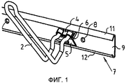
Фиг.1 вид в перспективе, показывающий крепление варианта выполнения держателя инструмента согласно изобретению к подвесному кронштейну;Fig. 1 is a perspective view showing the attachment of an embodiment of a tool holder according to the invention to a suspension bracket;
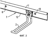
Фиг.2 вид в перспективе держателя инструмента с фиг.1, когда тот жестко прикреплен к подвесному кронштейну;FIG. 2 is a perspective view of the tool holder of FIG. 1, when the tool is rigidly attached to the hanging bracket;
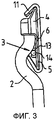
Фиг.3 частичный вид сбоку держателя инструмента с фиг.2, когда тот жестко прикреплен к подвесному кронштейну;Figure 3 is a partial side view of the tool holder of Figure 2, when it is rigidly attached to the hanging bracket;
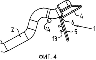
Фиг.4 частичный вид сбоку, показывающий конструкцию держателя инструмента с фиг.1-3;Fig. 4 is a partial side view showing the structure of the tool holder of Figs. 1-3;
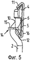
Фиг.5 частичный вид сбоку держателя инструмента с альтернативным фиксирующим устройством;Figure 5 is a partial side view of a tool holder with an alternative locking device;
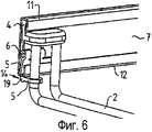
Фиг.6 частичный вид в перспективе, показывающий вариант выполнения держателя инструмента согласно изобретению, когда тот жестко прикреплен к подвесному кронштейну;Fig. 6 is a partial perspective view showing an embodiment of a tool holder according to the invention when it is rigidly attached to a suspension bracket;
Фиг.7 частичный вид сбоку держателя инструмента с фиг.6, когда тот жестко прикреплен к подвесному кронштейну;Fig.7 is a partial side view of the tool holder of Fig.6, when it is rigidly attached to the hanging bracket;
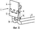
Фиг.8 частичный вид в перспективе, показывающий конструкцию держателя инструмента с фиг.6-7;Fig.8 is a partial perspective view showing the structure of the tool holder of Fig.6-7;
Фиг.9 частичный вид в перспективе альтернативного варианта выполнения держателя инструмента согласно фиг.6-8;Fig.9 is a partial perspective view of an alternative embodiment of the tool holder according to Fig.6-8;
Фиг.10-13 показывают дополнительный вариант выполнения держателя инструмента (без крюкового средства) согласно изобретению и различные этапы монтирования его на подвесной кронштейн;10-13 show an additional embodiment of a tool holder (without hook means) according to the invention and the various steps of mounting it on a suspension bracket;
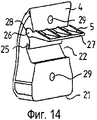
Фиг.14 вид в перспективе альтернативного варианта выполнения держателя инструмента (без крюкового средства) согласно фиг.10-13;Fig.14 is a perspective view of an alternative embodiment of the tool holder (without hook means) according to Fig.10-13;
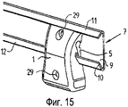
Фиг.15 вид в перспективе держателя инструмента с фиг.14, когда тот жестко прикреплен к подвесному кронштейну;Fig. 15 is a perspective view of the tool holder of Fig. 14, when it is rigidly attached to the hanging bracket;
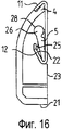
Фиг.16 вид сбоку держателя инструмента с фиг.14-15, когда тот жестко прикреплен к подвесному кронштейну; иFig.16 is a side view of the tool holder of Fig.14-15, when it is rigidly attached to the hanging bracket; and
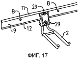
Фиг.17 вид в перспективе, в уменьшенном масштабе показывающий держатель инструмента согласно фиг.10-12 или, альтернативно, фиг.14-16 с крюковым средством, когда тот жестко прикреплен к подвесному кронштейну.Fig.17 is a perspective view, on a reduced scale, showing the tool holder according to Fig.10-12 or, alternatively, Fig.14-16 with hook means, when it is rigidly attached to the hanging bracket.
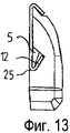
Со ссылкой сначала на фиг.1-4, которые показывают первый вариант выполнения держателя инструмента согласно изобретению, держатель инструмента содержит крепежное устройство 1, крюковое средство 2 (смотри фиг.17) и фиксирующее устройство 3. Крепежное устройство 1 содержит первый, верхний участок 4, к которому прикреплено крюковое средство 2 согласно этому варианту выполнения. Крепежное устройство 1 дополнительно содержит второй, нижний участок 5, который шарнирно присоединен к первому участку 4 посредством соединения 6. В этом варианте выполнения, первый участок 4 и второй участок 5 содержат общую пластину с вогнутым участком или пазом, образующим соединение 6. Соединение 6 ориентировано в том же направлении что и подвесной кронштейн 7, в которое крепежное устройство 1 должно быть разъемно смонтировано.Referring first to FIGS. 1-4, which show a first embodiment of a tool holder according to the invention, the tool holder comprises a
Подвесной кронштейн 7, который выполнен с возможностью прикручивания к стене через сквозные отверстия 8 или прикрепления к вертикально ориентированным колоннам или подвесным стойкам, содержит стенку 9, снабженную упомянутыми отверстиями 8. Первая, верхняя полка 11, которая загнута к центральной части или центру стенки 9 и расположена под острым углом к ней, присоединена на верхнем краю стенки 9, а вторая, нижняя полка 12, которая загнута к центральной части стенки 9 и расположена под острым углом к ней, присоединена на нижнем краю стенки 9. Как наилучшим образом показано на фиг.3, угол наклона и длина первой полки 11 может отличаться от угла наклона и длины второй полки 12. Альтернативно, и как показано на фиг.7, полки 11, 12 могут продолжаться перпендикулярно стенке 9, и могут быть загнуты на 90 градусов на определенном расстоянии от стенки, так чтобы их свободные концы (смотри краевой участок 10 на фиг.5) смотрели друг на друга. В смонтированном состоянии держателя инструмента соединение 6 расположено между полками 11, 12 и ориентировано параллельно им.
Наконец, держатель инструмента содержит фиксирующее устройство 3, которое в варианте выполнения изобретения согласно фиг.1-4 состоит из первого фиксирующего элемента 13 и второго фиксирующего элемента 14. Первый фиксирующий элемент 13 является C-образной секцией, выполненной из эластичного материала, которая прикреплена ко второму участку 5 крепежного устройства или выполнена как одно целое с ним. Второй фиксирующий элемент 14 является секцией в виде стержня, который прикреплен к крюковому средству 2 и который может быть введен в защелкивающееся зацепление с первым фиксирующим элементом 13. Фиксирующие элементы 13, 14 предпочтительно являются вытянутыми и ориентированы параллельно полкам 11, 12. Предпочтительно, если первый участок 4, второй участок 5 и первый фиксирующий элемент 13 крепежного устройства выполнены из пластика.Finally, the tool holder comprises a
Вариант выполнения держателя инструмента на фиг.5 отличается от варианта выполнения, описанного выше, тем, что он содержит другой тип фиксирующего устройства. В этом варианте выполнения, первый фиксирующий элемент образован самым отдаленным краевым участком 10 второй полки 12 и второй фиксирующий элемент 14 образован кольцевым, эластичным элементом 15, который сдвинут на одну ножку крюкового средства 2 (смотри фиг.6), и который имеет направленный вниз выступ 16, который при прикреплении крепежного устройства 1 к подвесному кронштейну 7 защелкивается под самый отдаленный краевой участок 10 второй полки 12 на его внутренней стороне.The embodiment of the tool holder in FIG. 5 differs from the embodiment described above in that it comprises another type of locking device. In this embodiment, the first locking element is formed by the
Держатели инструмента согласно фиг.1-5 монтируются на подвесной кронштейн 7 следующим образом. Держатель инструмента перемещается, немного наклоненным вперед, к подвесному кронштейну таким образом, что второй участок 5 крепежного устройства мог быть вставлен в пространство между второй полкой 12 и стенкой 9 подвесного стержня. Держатель инструмента затем прижимается к подвесному кронштейну так, что первый участок 4 крепежного устройства вводится в пространство между первой полкой 11 и стенкой 9 подвесного кронштейна. Наконец, держатель инструмента энергично проталкивается вниз с помощью крюкового средства, тем самым второй фиксирующий элемент 14 защелкивается в первый фиксирующий элемент 13 и прочно закрепляет держатель инструмента на месте; смотри последовательность монтирования фиг.10-13. Все это может выполняться всего лишь одной рукой.The tool holders according to figures 1-5 are mounted on the hanging
Держатель инструмента открепляется от подвесного кронштейна путем, обратным порядку последовательности монтирования, описанному выше. Поскольку операция открепления выполняется захватом крюкового средства (и проталкивания его вверх) относительно малое усилие требуется, не смотря на то, что держатель инструмента прочно прикреплен к подвесному кронштейну.The tool holder is detached from the suspension bracket in the reverse order of the mounting sequence described above. Since the detachment operation is carried out by gripping the hook means (and pushing it upward) a relatively small force is required, despite the fact that the tool holder is firmly attached to the hanging bracket.
Фиг.6-8 показывают альтернативный вариант выполнения держателя инструмента. В этом варианте выполнения, первый участок 4 крепежного устройства 1 шарнирно присоединен к его второму участку 5 посредством шарнирного соединения 6. Более того, подвесной кронштейн 7 этого варианта выполнения от подвесного кронштейна, показанного на фиг.1-5, тем, что первая и вторая полки 11, 12 не являются плоскими и не образуют острый угол со стенкой 9, но выступают из стенки перпендикулярно ей и изогнуты под прямыми углами друг к другу на расстоянии от стенки, как описано выше. Паз 12 или, альтернативно, выступ (не показан) выполнен на горизонтальном участке 18 второй полки 12, а кольцевой, эластичный элемент 15, имеющий выпуклость 19, был сдвинут на одну ножку крюкового средства 2. Паз 17 и выпуклость 19 служат в качестве первого фиксирующего элемента 13 и второго фиксирующего элемента 14, соответственно, фиксирующего устройства 3, причем выпуклость 19 защелкивается в паз 17 или, альтернативно, защелкивается за упомянутый выступ при прикреплении крепежного устройства 1 к подвесному кронштейну 7.Figures 6-8 show an alternative embodiment of a tool holder. In this embodiment, the
Фиг.9 показывает альтернативный вариант выполнения держателя инструмента на фиг.6-8. Отличие между этим держателем инструмента и держателем инструмента на фиг.6-8 заключается в том, что первый участок 4 и второй участок 5 крепежного устройства 1, а также соединение 6, выполнены целиком, то есть они образуют единый узел. Соединение 6 выполнено в виде трубчатой секции.Fig.9 shows an alternative embodiment of the tool holder in Fig.6-8. The difference between this tool holder and the tool holder in Fig.6-8 is that the
Еще один вариант выполнения держателя инструмента согласно изобретению и его вариант, показаны на фиг.10-17, а на фиг.10-13 показано их монтирование на подвесной кронштейн, описанное выше совместно с держателями инструмента согласно фиг.1-5. В этих вариантах выполнения, крепежное устройство 1 состоит из корпуса, который имеет длину, значительно большую, чем ширина стенки 9 подвесного кронштейна 7. Крепежное устройство 1 также имеет значительную толщину. Верхний участок крепежного устройства, в его смонтированном состоянии, сужается по форме и служит в качестве его упомянутого первого участка 4. Предпочтительно, первый участок имеет форму, которая соответствует форме пространства между первой полкой 11 и стенкой 9 подвесного кронштейна 7. Как показано на фиг.17, крюковое средство 2 прикреплено к нижнему, большему участку крепежного устройства 1. Однако, для простоты пояснения, крюковое средство не показано на фиг.10-16.Another embodiment of the tool holder according to the invention and its variant are shown in FIGS. 10-17, and FIGS. 10-13 show their mounting on the hanging bracket described above together with the tool holders according to FIGS. 1-5. In these embodiments, the
Между первым участком 4 крепежного устройства и его нижней поверхностью 21, как видно в его смонтированном состоянии, выполнена выемка 22, которая проходит в крепежное устройство из его внутренней поверхности 23 и которое ориентировано параллельно нижней поверхности 21 между боковыми краями 24 крепежного устройства (только один из которых показан на фигурах). Форма выемки 22 соответствует форме пространства между второй полкой 12 и стенкой 9 подвесного кронштейна плюс толщина второй полки 12, смотри в частности фиг.13. Самый нижний край выемки 22, на ее внутренней поверхности 23, имеет направленный вверх выступ 25, который служит в качестве второго фиксирующего элемента 14 фиксирующего устройства, как будет описано ниже.Between the
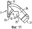
Со ссылкой в частности на фиг.14, второй участок 5 крепежного устройства 1 имеет форму крыла, один край которого в продольном направлении имеет частично цилиндрическую секцию 26. Предпочтительно, крыло имеет сужающуюся форму от секции 26 до его противоположного края 27. Крыло или второй участок 5 крепежного устройства шарнирно введен своей частично цилиндрической секцией 26 в соответствующую выемку 28, выполненную на внутренней стенке выемки 22 и проходящую параллельно нижней поверхности 21 крепежного устройства.With reference particularly to FIG. 14, the
Монтирование держателя инструмента на подвесной кронштейн 7 было показано на фиг.10-13 и описано выше и, следовательно, больше не будет разъясняться здесь. Однако фиг.12-13 будут описаны более подробно. Когда крепежное устройство 1 с крюковым средством (не показано) расположено, как показано на фиг.12, выступ 25 опирается на наружную поверхность второй полки 12 смежно стенке 9, то есть на изгибе подвесного кронштейна 7. Толкая вниз крюковое средство 2, выступ 25 вдавливается за вторую полку 12, чтобы защелкнуться к стенке 9, тем самым держатель инструмента прикрепляется к подвесному кронштейну 7. Таким образом, изгиб 20 подвесного кронштейна между стенкой 9 и его второй полкой 12 служит в качестве первого фиксирующего элемента 13 фиксирующего устройства, в то время как выступ 25 крепежного устройства служит в качестве его второго фиксирующего элемента 14.Mounting the tool holder on the
Фиг.14-16 показывает альтернативный вариант выполнения держателя инструмента на фиг.10-13. Отличие между двумя вариантами выполнения заключается в том, что выступ 25, расположенный на внутренней поверхности 23 крепежного устройства на фиг.10-13, был удален и взамен расположен на внутреннем участке выемки 22, то есть на расстоянии от внутренней поверхности 23 и под пазом 28. При монтировании держателя инструмента, а именно на последнем этапе операции монтирования, соответствующего этапу монтирования на фиг.12, выступ 25 защелкивается за самый отдаленный краевой участок 10 второй полки 12, тем самым держатель инструмента прикрепляется к подвесному кронштейну, смотри фиг.15 и 16. Таким образом, самый отдаленный краевой участок 10 служит в качестве первого фиксирующего элемента 13 фиксирующего устройства, в то время как выступ 25 служит в качестве его второго фиксирующего элемента 14.Figures 14-16 show an alternative embodiment of the tool holder of figures 10-13. The difference between the two options is that the
Чтобы позволить использование держателя инструмента согласно изобретению без подвесного кронштейна, крепежное устройство 1 снабжается парой сквозных отверстий 29 для прикручивания держателя инструмента непосредственно к опоре, например, стене. Конечно, отверстия 29 могут также использоваться, чтобы прочно прикрепить держатель инструмента к подвесному кронштейну.To allow the use of the tool holder according to the invention without a hanging bracket, the mounting
В этих вариантах выполнения держателя инструмента согласно изобретению, крепежное устройство содержит фиксирующее устройство. Однако это фиксирующее устройство не является абсолютно необходимым, поскольку крюковое средство прикреплено к первому, верхнему участку крепежного устройства, либо непосредственно, либо опосредовано. В случае подвешенного к крюку объекта и прикладывающей к нему нагрузки, первый и второй участки крепежного устройства будут прижиматься к стенке подвесного кронштейна суммарным моментом, и держатель инструмента будет прикреплен с возможностью смещения к подвесному кронштейну. Однако фиксирующее устройство предотвращает расцепление держателя инструмента с рейкой в результате направленного вверх давления или удара по крюковому средству и также предотвращает боковое смещение держателя инструмента.In these embodiments of the tool holder according to the invention, the mounting device comprises a locking device. However, this locking device is not absolutely necessary, since the hook means is attached to the first, upper portion of the mounting device, either directly or indirectly. In the case of an object suspended from the hook and applying a load to it, the first and second sections of the mounting device will be pressed against the wall of the suspension bracket by the total moment, and the tool holder will be attached with the possibility of bias to the suspension bracket. However, the locking device prevents uncoupling of the tool holder from the rail as a result of upward pressure or impact on the hook means and also prevents lateral displacement of the tool holder.
Изобретение не ограничено тем, что описано выше и показано на чертежах, и может быть модифицировано в объеме прилагаемых пунктов формулы изобретения. Например, возможно применить фиксирующее устройство одного варианта выполнения держателя инструмента к другому варианту выполнения держателя инструмента в продемонстрированных рабочих примерах изобретения.The invention is not limited to what is described above and shown in the drawings, and can be modified to the extent of the attached claims. For example, it is possible to apply a locking device of one embodiment of a tool holder to another embodiment of a tool holder in the illustrated working examples of the invention.
Claims (10)
Applications Claiming Priority (5)
| Application Number | Priority Date | Filing Date | Title |
|---|---|---|---|
| US6405808P | 2008-02-13 | 2008-02-13 | |
| SE0800319-6 | 2008-02-13 | ||
| SE0800319A SE531733C2 (en) | 2008-02-13 | 2008-02-13 | Tool carriers |
| US61/064,058 | 2008-02-13 | ||
| PCT/EP2009/000949 WO2009100892A1 (en) | 2008-02-13 | 2009-02-11 | Tool holder |
Publications (2)
| Publication Number | Publication Date |
|---|---|
| RU2010137834A RU2010137834A (en) | 2012-03-20 |
| RU2492785C2 true RU2492785C2 (en) | 2013-09-20 |
Family
ID=40863497
Family Applications (1)
| Application Number | Title | Priority Date | Filing Date |
|---|---|---|---|
| RU2010137834/12A RU2492785C2 (en) | 2008-02-13 | 2009-02-11 | Tool holder |
Country Status (8)
| Country | Link |
|---|---|
| US (2) | US8662322B2 (en) |
| EP (1) | EP2249683B1 (en) |
| AT (1) | ATE519401T1 (en) |
| DK (1) | DK2249683T3 (en) |
| PL (1) | PL2249683T3 (en) |
| RU (1) | RU2492785C2 (en) |
| SE (1) | SE531733C2 (en) |
| WO (1) | WO2009100892A1 (en) |
Cited By (1)
| Publication number | Priority date | Publication date | Assignee | Title |
|---|---|---|---|---|
| RU199642U1 (en) * | 2020-06-16 | 2020-09-11 | Сергей Юрьевич Метлицкий | DEVICE HOLDING DEVICE FOR CONTROL OF WATER LEAKAGE ON THE PIPE |
Families Citing this family (31)
| Publication number | Priority date | Publication date | Assignee | Title |
|---|---|---|---|---|
| US8061537B2 (en) * | 2008-02-13 | 2011-11-22 | Elfa International | Tool holder |
| SE531733C2 (en) | 2008-02-13 | 2009-07-21 | Elfa Int Ab | Tool carriers |
| US20100096347A1 (en) * | 2008-10-16 | 2010-04-22 | Travis Theobald | Apparatus, System, and Method for Selectively Mounting a Hitch Mount Rack on a Building Wall |
| GB2480553A (en) * | 2011-05-19 | 2011-11-23 | Claire Burley | Carriage device for attaching a scooter to a pushchair handle |
| US8800212B2 (en) | 2011-11-23 | 2014-08-12 | Parallax Group International, Llc | Wall mounting devices |
| SE537842C2 (en) * | 2012-06-19 | 2015-11-03 | Elfa Int Ab | Holding device for carrier with elongated holes |
| KR101326041B1 (en) * | 2012-08-20 | 2013-11-07 | (주)에이스 힌지텍 | (a panel for hanging and device for hanging using the same |
| US9657890B2 (en) * | 2013-03-05 | 2017-05-23 | Javier Botello | Cooperatively coupled holding system and method |
| US20150068995A1 (en) * | 2013-09-09 | 2015-03-12 | Curtis G. Hartman | Holder assembly for tubular containers |
| USD731678S1 (en) * | 2013-11-21 | 2015-06-09 | Lite Guard Safety Solutions Pty Ltd. | Lifting lug |
| US9629457B2 (en) | 2014-06-20 | 2017-04-25 | Kohler Co. | Bathing area accessories |
| USD762777S1 (en) | 2015-03-23 | 2016-08-02 | Parallax Group International, Llc | Hook bracket for wall mounting devices |
| US9975237B2 (en) * | 2016-06-09 | 2018-05-22 | Andrew Norris | Platform with removable pegs for organizing sockets |
| US10051978B2 (en) * | 2016-10-27 | 2018-08-21 | Anil K. Gupta | Pegboard adapter and method |
| CN106346434A (en) * | 2016-11-28 | 2017-01-25 | 广西大学 | Workpiece table matching for benchwork platform |
| US20180231176A1 (en) * | 2017-02-10 | 2018-08-16 | Pro-Mart Industries, Inc. | Storage brackets with movable storage hooks |
| US10173314B1 (en) * | 2017-09-22 | 2019-01-08 | Jin-Lan Lai | Tool hanger |
| US11583074B2 (en) | 2017-10-27 | 2023-02-21 | Elfa International Ab | Wall-mounted, configurable storage system |
| US10729244B2 (en) * | 2018-06-04 | 2020-08-04 | A.L. Hansen Manufacturing Co. | Reconfigurable storage assembly |
| US11375812B2 (en) | 2018-09-12 | 2022-07-05 | Elfa International Ab | Wall-mounted, configurable storage system |
| US11026515B2 (en) | 2018-11-15 | 2021-06-08 | Series International, Llc | Beam seating system |
| US10681983B2 (en) * | 2018-11-15 | 2020-06-16 | Series International, Llc | Beam seating system |
| CN109579310B (en) * | 2019-01-14 | 2020-12-25 | 安徽炭元高新科技集团有限公司 | Intelligent water heater convenient to dismantle |
| SE543835C2 (en) | 2019-12-23 | 2021-08-10 | Elfa Int Ab | Shelf storage system comprising hang standards with screw holes at distances corresponding to desired bracket to bracket distances |
| EP4142543A1 (en) | 2020-04-30 | 2023-03-08 | Elfa International AB | Suspension system comprising a rear rail arranged with flanges at least partially extending in different directions and a hangstandard arrangable thereto |
| SE544174C2 (en) | 2020-04-30 | 2022-02-22 | Elfa Int Ab | Hang standard and storage system including the hang standard |
| US20220225769A1 (en) * | 2021-01-20 | 2022-07-21 | Stuart Brown | Object hanging system and method |
| US20230102705A1 (en) * | 2021-09-29 | 2023-03-30 | Innovation Lock, Llc | Devices, systems and methods for hanging and securing items for display |
| US11825965B2 (en) * | 2021-12-16 | 2023-11-28 | Mark Olmstead | System for mounting objects to a structure |
| USD976085S1 (en) * | 2022-05-24 | 2023-01-24 | Paul James Kosch | Slatwall accessory |
| USD976084S1 (en) * | 2022-05-24 | 2023-01-24 | Paul James Kosch | Slatwall hook |
Citations (6)
| Publication number | Priority date | Publication date | Assignee | Title |
|---|---|---|---|---|
| US4308961A (en) * | 1980-05-05 | 1982-01-05 | Kunce Thomas M | Article supporting structure |
| JPS62211014A (en) * | 1986-03-11 | 1987-09-17 | 株式会社 玉俊工業所 | Wall surface constitutional member for displaying commodity |
| DE9115361U1 (en) * | 1991-12-11 | 1992-02-13 | Fent, Josef, 8200 Rosenheim, De | |
| RU30790U1 (en) * | 2002-12-11 | 2003-07-10 | Пряжкин Александр Владимирович | Prefabricated panel construction |
| DE202004004034U1 (en) * | 2004-03-12 | 2005-07-28 | Emil Lux Gmbh & Co. Kg | Goods support for use in e.g. shops, has holding hooks that project downwards for hanging on lattice bar, and securing hook for hooking on another lattice bar, where securing hook is part of one-piece securing lever and is made of plastic |
| WO2006067999A1 (en) * | 2004-12-24 | 2006-06-29 | Sugatsune Kogyo Co., Ltd. | Engagement member for display device |
Family Cites Families (28)
| Publication number | Priority date | Publication date | Assignee | Title |
|---|---|---|---|---|
| US3094305A (en) * | 1962-07-02 | 1963-06-18 | Prec Parts Co Inc | Display clip |
| US3245495A (en) * | 1964-01-22 | 1966-04-12 | Jr Thomas M Wells | Scaffold |
| GB1479528A (en) * | 1975-04-10 | 1977-07-13 | Goetaverken Ab | Scaffolding bracket |
| US4674721A (en) * | 1986-07-01 | 1987-06-23 | Trion Industries Inc. | Removably mounted merchandise display hook |
| SE460252B (en) * | 1988-02-10 | 1989-09-25 | Sparring Elfa Ab | BAERLIST FOR HAENGSKENOR |
| US4867623A (en) * | 1989-02-10 | 1989-09-19 | Aeroquip Corporation | Ring fitting for dunnage track |
| US5135194A (en) * | 1989-03-10 | 1992-08-04 | Mccalla/Lackey Corporation | Wall mounting system |
| US5265992A (en) * | 1990-11-15 | 1993-11-30 | Ancra Corporation | Tie down fitting for retaining objects to the floor or side wall of a vehicle |
| US5752791A (en) * | 1993-05-17 | 1998-05-19 | Wabash National Corporation | Cargo securement assembly |
| US5725107A (en) * | 1995-09-19 | 1998-03-10 | Dembicks; Andrew E. | Locking holder for interchangeable bit member |
| US5918842A (en) * | 1996-09-05 | 1999-07-06 | Garfinkle; Benjamin L. | Fixture tag molding adapter |
| US5740927A (en) * | 1997-01-09 | 1998-04-21 | Zag Ltd. | Tool rack |
| US5807047A (en) * | 1997-03-04 | 1998-09-15 | Collins And Aikman Products, Co. | Cargo transport assembly including retaining bracket for cargo support beam |
| CA2200422C (en) * | 1997-03-19 | 2002-05-07 | Jan B. Leurdijk | Storage track system |
| US5853092A (en) * | 1997-08-28 | 1998-12-29 | Goodman; Gregory L. | Self-adapting tool rack |
| US6675980B2 (en) * | 1999-04-30 | 2004-01-13 | Glenn Alan Ehrgott | Storage device mounting system |
| US6364141B1 (en) * | 1999-04-30 | 2002-04-02 | Glenn Alan Ehrgott | Fast track shelving system |
| DE10039501A1 (en) * | 2000-08-12 | 2002-02-28 | Grammer Ag | Adjusting means |
| GB0214400D0 (en) * | 2002-06-21 | 2002-07-31 | Newell Ltd | Shelving system |
| US6986430B2 (en) * | 2003-03-12 | 2006-01-17 | Meir Oren | System for holding and organizing articles |
| US7527156B2 (en) * | 2005-07-12 | 2009-05-05 | Whirlpool Corporation | Tool caddy |
| US20070017886A1 (en) * | 2005-07-20 | 2007-01-25 | Jui-Chien Kao | Suspension display rack |
| US7427053B2 (en) * | 2005-11-04 | 2008-09-23 | Clairson, Inc. | Hook/hanger component mounting systems, components thereof, and related methods |
| GB2433091A (en) * | 2006-02-03 | 2007-06-13 | Busybase Ltd | Clip with biased latch |
| US20080000853A1 (en) * | 2006-06-13 | 2008-01-03 | Jung Li Huang | Holder for implements |
| US7757869B2 (en) * | 2007-12-26 | 2010-07-20 | Stephen Lawson | Hanger adaptable for use with a slatwall track and a retainer therefor |
| SE531733C2 (en) | 2008-02-13 | 2009-07-21 | Elfa Int Ab | Tool carriers |
| US8061537B2 (en) * | 2008-02-13 | 2011-11-22 | Elfa International | Tool holder |
-
2008
- 2008-02-13 SE SE0800319A patent/SE531733C2/en unknown
-
2009
- 2009-02-11 PL PL09709646T patent/PL2249683T3/en unknown
- 2009-02-11 US US12/735,717 patent/US8662322B2/en active Active
- 2009-02-11 AT AT09709646T patent/ATE519401T1/en active
- 2009-02-11 EP EP09709646A patent/EP2249683B1/en active Active
- 2009-02-11 DK DK09709646.5T patent/DK2249683T3/en active
- 2009-02-11 RU RU2010137834/12A patent/RU2492785C2/en active
- 2009-02-11 WO PCT/EP2009/000949 patent/WO2009100892A1/en active Application Filing
-
2014
- 2014-01-17 US US14/157,956 patent/US8960454B2/en active Active
Patent Citations (6)
| Publication number | Priority date | Publication date | Assignee | Title |
|---|---|---|---|---|
| US4308961A (en) * | 1980-05-05 | 1982-01-05 | Kunce Thomas M | Article supporting structure |
| JPS62211014A (en) * | 1986-03-11 | 1987-09-17 | 株式会社 玉俊工業所 | Wall surface constitutional member for displaying commodity |
| DE9115361U1 (en) * | 1991-12-11 | 1992-02-13 | Fent, Josef, 8200 Rosenheim, De | |
| RU30790U1 (en) * | 2002-12-11 | 2003-07-10 | Пряжкин Александр Владимирович | Prefabricated panel construction |
| DE202004004034U1 (en) * | 2004-03-12 | 2005-07-28 | Emil Lux Gmbh & Co. Kg | Goods support for use in e.g. shops, has holding hooks that project downwards for hanging on lattice bar, and securing hook for hooking on another lattice bar, where securing hook is part of one-piece securing lever and is made of plastic |
| WO2006067999A1 (en) * | 2004-12-24 | 2006-06-29 | Sugatsune Kogyo Co., Ltd. | Engagement member for display device |
Cited By (1)
| Publication number | Priority date | Publication date | Assignee | Title |
|---|---|---|---|---|
| RU199642U1 (en) * | 2020-06-16 | 2020-09-11 | Сергей Юрьевич Метлицкий | DEVICE HOLDING DEVICE FOR CONTROL OF WATER LEAKAGE ON THE PIPE |
Also Published As
| Publication number | Publication date |
|---|---|
| PL2249683T3 (en) | 2012-01-31 |
| ATE519401T1 (en) | 2011-08-15 |
| SE0800319L (en) | 2009-07-21 |
| US20110042333A1 (en) | 2011-02-24 |
| EP2249683A1 (en) | 2010-11-17 |
| EP2249683B1 (en) | 2011-08-10 |
| US20140145049A1 (en) | 2014-05-29 |
| WO2009100892A1 (en) | 2009-08-20 |
| US8662322B2 (en) | 2014-03-04 |
| RU2010137834A (en) | 2012-03-20 |
| DK2249683T3 (en) | 2011-11-14 |
| SE531733C2 (en) | 2009-07-21 |
| US8960454B2 (en) | 2015-02-24 |
Similar Documents
| Publication | Publication Date | Title |
|---|---|---|
| RU2492785C2 (en) | Tool holder | |
| US6189847B1 (en) | Apparatus for attaching a wide range of article supporting fixtures to a variety of support surfaces | |
| US8061537B2 (en) | Tool holder | |
| EP2066206B1 (en) | Adhesively mountable angled wall shelf | |
| US20120273636A1 (en) | Hanger holder accessory and system | |
| US20080210827A1 (en) | Display hanger for curtain rod | |
| US20110017900A1 (en) | Mounting bracket for a pump | |
| WO2005107536A3 (en) | A system for holding implements | |
| US20140224754A1 (en) | Anti-sway shower caddy | |
| US20230045766A1 (en) | Systems for hanging articles | |
| US5673884A (en) | Suction-mounted holding devices | |
| CA2430006A1 (en) | Shelving unit having integrated hooks with hanger rod | |
| CA3029803C (en) | Article mounting device | |
| KR20100053039A (en) | Bike carrier attached wall | |
| KR20050021636A (en) | Display stand | |
| US5551580A (en) | Slidable storage wall-mount | |
| JP3904596B1 (en) | Wall material holder | |
| US7770865B2 (en) | Hang level suspension system | |
| EP2344006B1 (en) | Storage system comprising upright segments and joint piece | |
| US20130112846A1 (en) | Broom rest and/or broom holder | |
| US20080302739A1 (en) | Organizing and storing devices, systems, and methods | |
| KR200434695Y1 (en) | Exhibitive rack | |
| US20240084963A1 (en) | Over-door, hanging apparatus | |
| JP3022883U (en) | Organizer locking device | |
| JP4301090B2 (en) | Hanging structure for cabinet |