RU2492435C9 - Filler cryostat for infrared detector - Google Patents
Filler cryostat for infrared detector Download PDFInfo
- Publication number
- RU2492435C9 RU2492435C9 RU2012107038/28A RU2012107038A RU2492435C9 RU 2492435 C9 RU2492435 C9 RU 2492435C9 RU 2012107038/28 A RU2012107038/28 A RU 2012107038/28A RU 2012107038 A RU2012107038 A RU 2012107038A RU 2492435 C9 RU2492435 C9 RU 2492435C9
- Authority
- RU
- Russia
- Prior art keywords
- cryostat
- cylinder
- liquefied gas
- cooled platform
- filler neck
- Prior art date
Links
- 239000000945 filler Substances 0.000 title claims abstract description 40
- 238000009825 accumulation Methods 0.000 claims abstract description 5
- RYGMFSIKBFXOCR-UHFFFAOYSA-N Copper Chemical compound [Cu] RYGMFSIKBFXOCR-UHFFFAOYSA-N 0.000 claims description 7
- 238000009835 boiling Methods 0.000 claims description 7
- 229910052802 copper Inorganic materials 0.000 claims description 7
- 239000010949 copper Substances 0.000 claims description 7
- 229920002313 fluoropolymer Polymers 0.000 claims description 7
- 230000005855 radiation Effects 0.000 claims description 7
- 238000007789 sealing Methods 0.000 claims description 7
- 229920001971 elastomer Polymers 0.000 claims description 6
- 239000007789 gas Substances 0.000 abstract description 47
- 239000003915 liquefied petroleum gas Substances 0.000 abstract 3
- 239000000126 substance Substances 0.000 abstract 1
- IJGRMHOSHXDMSA-UHFFFAOYSA-N nitrogen Substances N#N IJGRMHOSHXDMSA-UHFFFAOYSA-N 0.000 description 35
- 229910052757 nitrogen Inorganic materials 0.000 description 19
- 239000007788 liquid Substances 0.000 description 7
- 238000001816 cooling Methods 0.000 description 4
- 239000000463 material Substances 0.000 description 4
- 239000002594 sorbent Substances 0.000 description 4
- OKTJSMMVPCPJKN-UHFFFAOYSA-N Carbon Chemical compound [C] OKTJSMMVPCPJKN-UHFFFAOYSA-N 0.000 description 3
- 238000001704 evaporation Methods 0.000 description 3
- 238000005192 partition Methods 0.000 description 3
- 239000011159 matrix material Substances 0.000 description 2
- 238000005086 pumping Methods 0.000 description 2
- 230000000087 stabilizing effect Effects 0.000 description 2
- 229910001220 stainless steel Inorganic materials 0.000 description 2
- 239000010935 stainless steel Substances 0.000 description 2
- 235000018185 Betula X alpestris Nutrition 0.000 description 1
- 235000018212 Betula X uliginosa Nutrition 0.000 description 1
- XUIMIQQOPSSXEZ-UHFFFAOYSA-N Silicon Chemical compound [Si] XUIMIQQOPSSXEZ-UHFFFAOYSA-N 0.000 description 1
- 229910000831 Steel Inorganic materials 0.000 description 1
- 230000015572 biosynthetic process Effects 0.000 description 1
- 238000006073 displacement reaction Methods 0.000 description 1
- 229910052732 germanium Inorganic materials 0.000 description 1
- GNPVGFCGXDBREM-UHFFFAOYSA-N germanium atom Chemical compound [Ge] GNPVGFCGXDBREM-UHFFFAOYSA-N 0.000 description 1
- 229910052738 indium Inorganic materials 0.000 description 1
- APFVFJFRJDLVQX-UHFFFAOYSA-N indium atom Chemical compound [In] APFVFJFRJDLVQX-UHFFFAOYSA-N 0.000 description 1
- 230000014759 maintenance of location Effects 0.000 description 1
- 238000000034 method Methods 0.000 description 1
- 230000003287 optical effect Effects 0.000 description 1
- 229920006395 saturated elastomer Polymers 0.000 description 1
- 229910052710 silicon Inorganic materials 0.000 description 1
- 239000010703 silicon Substances 0.000 description 1
- 239000010959 steel Substances 0.000 description 1
- 238000003466 welding Methods 0.000 description 1
Images
Landscapes
- Filling Or Discharging Of Gas Storage Vessels (AREA)
Abstract
Description
Изобретение относится к конструктивным элементам регистрирующей техники, а именно, к элементам конструкции фоточувствительных приборов, предназначенных для регистрации инфракрасного (ИК) излучения, в частности, к криостатам для охлаждаемых многоэлементных фотоприемников.The invention relates to structural elements of a recording technique, namely, to structural elements of photosensitive devices intended for recording infrared (IR) radiation, in particular, to cryostats for cooled multi-element photodetectors.
Известен заливной криостат для приемника инфракрасного излучения (Б.И. Формозов. Аэрокосмические фотоприемные устройства в видимом и инфракрасном диапазонах: Учебное пособие / СПбГУАП, СПб., 2002 г., 120 с., стр.50-52), содержащий корпус, размещенные во внутреннем объеме, ограничиваемом корпусом, рабочую камеру, заливной узел криостатирования, сформированный перегородкой, отграничивающей рабочую камеру, в виде контейнера для сжиженного газа - азота, снабженного заливной горловиной, крионасос, трубчатые парозаборники испаряющего азота, предназначенные для циркуляционного охлаждения парами азота фотоприемника, размещенного в рабочей камере. Трубчатые парозаборники испаряющегося азота реализованы с возможностью забора паров из объема контейнера для сжиженного газа и подачи их в рабочую камеру, выполненную с возможностью дренажа паров азота. Корпус со стороны рабочей камеры снабжен входным окном из лейкосапфира диаметром 80 мм. В рабочей камере на некотором расстоянии от входного окна соосно размещено охлаждаемое окно из лейкосапфира диаметром 60 мм, к которому прижата пластина из германия марки ГМО-1 диаметром 60 мм, образуя полосовой ИК-фильтр, установленный в рабочей камере посредством фланца, соединенного индиевым разборным сочленением с перегородкой, отграничивающей рабочую камеру. Перегородка установлена во внутреннем объеме, ограничиваемом корпусом, посредством опор, расположенных в рабочей камере и примыкающих к корпусу. Перегородка снабжена крионасосом на основе березового активированного угля, а корпус снабжен вакуумным вентилем. В рабочей камере на некотором расстоянии от полосового фильтра соосно установлен фотоприемник, соединенный с наружным разъемом типа РГТС-50.Known filler cryostat for the infrared radiation receiver (B. I. Formozov. Aerospace photodetectors in the visible and infrared ranges: Textbook / SPbGUAP, SPb., 2002, 120 S., p. 50-52), containing the housing, in the internal volume limited by the housing, the working chamber, the cryostatic filling unit formed by a partition delimiting the working chamber, in the form of a container for liquefied gas - nitrogen, equipped with a filler neck, a cryopump, tubular vapor inlets of evaporating nitrogen, are intended ennye for circulating cooling photodetector pairs of nitrogen, arranged in the working chamber. Tubular vapor intakes of evaporating nitrogen are implemented with the possibility of taking vapors from the volume of the liquefied gas container and supplying them to a working chamber configured to drain nitrogen vapors. The case on the side of the working chamber is equipped with an input window of leucosapphire with a diameter of 80 mm. A cooled window made of leucosapphire 60 mm in diameter is coaxially placed in the working chamber at some distance from the entrance window, to which a GMO-1 germanium plate is pressed against 60 mm in diameter, forming a band-pass IR filter installed in the working chamber through a flange connected by an indium collapsible joint with a partition delimiting the working chamber. The partition is installed in the internal volume, limited by the housing, by means of supports located in the working chamber and adjacent to the housing. The baffle is equipped with a cryopump based on birch activated carbon, and the casing is equipped with a vacuum valve. A photodetector connected to an external connector of the RGTS-50 type is coaxially mounted in the working chamber at some distance from the band-pass filter.
Несмотря на широкое разнообразие конструкций криостатов не для всех видов работ, связанных с регистрацией ИК излучения, можно выбрать оптимально подходящую конструкцию. Нередко, оказывается, необходимо специальное исполнение, обеспечивающее стабильность взаимного расположения всех элементов фотоприемного устройства, размещенных в заднем рабочем отрезке оптической системы, возможность юстировки, а также работоспособность окном вниз, вверх, вбок и т.п. Приведенный криостат удобен при работе с наземными телескопами системы Кассегрена, с которыми криостат должен работать в положении окном вверх. В этом случае заливную горловину герметизируют пробкой. Для охлаждения и криостатирования фотоприемников применяют циркуляционное охлаждение парами испаряющегося азота. В этих целях осуществляют парозаборником сообщение объемов рабочей камеры и контейнера для сжиженного газа. Для работы в положении окном вверх или в положении окном вбок парозаборники выполняют по определенной схеме.Despite the wide variety of designs of cryostats, not for all types of work related to the registration of infrared radiation, it is possible to choose the most suitable design. Often, it turns out that a special design is needed to ensure the stability of the mutual arrangement of all the elements of the photodetector placed in the rear working segment of the optical system, the possibility of adjustment, as well as the operability of the window down, up, sideways, etc. The cryostat is convenient for working with ground-based telescopes of the Cassegrain system, with which the cryostat must work in the window up position. In this case, the filler neck is sealed with a stopper. To cool and cryostat photodetectors, circulating cooling by vapor of evaporating nitrogen is used. For these purposes, the intake is carried out message volumes of the working chamber and the container for liquefied gas. To work in the window up or in the lateral window position, the steam intakes are performed according to a certain pattern.
К недостаткам вышеприведенного технического решения относится узость диапазона пространственных ориентации криостата при его работе относительно горизонта. Причины, препятствующие достижению технического результата, носят конструктивный характер. Криостат предназначен для работы только в одном, фиксированном, положении. Для смены положения необходимы конструктивные изменения. Если криостат выполнен с парозаборниками, обеспечивающими его работу окном вверх, то при работе криостата окном вниз, несмотря на откачку насыщенных паров, жидкий азот будет просто выливаться в полость фотоприемника, пока его уровень не сравняется с уровнем парозаборников.The disadvantages of the above technical solutions include the narrow range of spatial orientation of the cryostat when it is working relative to the horizon. The reasons that impede the achievement of a technical result are constructive. The cryostat is designed to operate in only one fixed position. To change the position, structural changes are necessary. If the cryostat is made with intakes that ensure its operation with the window up, then when the cryostat is operated with the window down, despite the pumping out of saturated vapors, liquid nitrogen will simply pour into the cavity of the photodetector until its level is equal to the level of the intakes.
В качестве ближайшего аналога выбран заливной криостат для приемника инфракрасного излучения (патент РФ №2406946 на изобретение, МПК: 8 F25B 19/00), содержащий корпус с входным окном, размещенные во внутреннем объеме, ограничиваемом корпусом, рабочую камеру с охлаждаемой платформой, расположенной напротив окна, заливной узел криостатирования охлаждаемой платформы, выполненный в виде баллона для сжиженного, газа на котором в рабочей камере смонтирована охлаждаемая платформа, контейнер под сорбент, расположенный в объеме баллона. Баллон для сжиженного газа снабжен заливной горловиной из коаксиально расположенных трубок. На внешней поверхности баллона для сжиженного газа, выходящей в объем рабочей камеры, размещена охлаждаемая платформа. Охлаждаемая платформа связана с корпусом посредством подвешивающих ее упруго натянутых струн. Корпус снабжен передним фланцем с входным окном, напротив которого расположена охлаждаемая платформа. Заливная горловина выполнена из трех тонкостенных коаксиально расположенных с зазором трубок размерами, мм: ⌀8×0,2; ⌀10×0,2; ⌀1×20,2. В качестве материала трубок использована нержавеющая сталь. Струны выполнены максимально возможной длины из материала, обеспечивающего им высокую механическую прочность и низкую теплопроводность, и расположены в плоскости, параллельной плоскости охлаждаемой платформы. Максимально возможная длина струн обеспечена их расположением, при котором в плоскости, параллельной плоскости охлаждаемой платформы, струнами образован четырехугольник с прямыми углами, при этом «теплые» концы струн соединены с корпусом, а «холодные» - с охлаждаемой платформой. В криостате «теплые» концы струн соединены с корпусом сваркой, а «холодные» соединены с охлаждаемой платформой посредством промежуточных деталей, механически закрепленных к охлаждаемой платформе. Охлаждаемая платформа выполнена из меди, а промежуточные детали - из нержавеющей стали. В качестве материала струн использована проволока марки Х20Н80. Заливная горловина поверх коаксиально расположенных трубок снабжена фторопластовым колпачком.As the closest analogue, a jellied cryostat for an infrared radiation receiver (RF patent No. 2406946 for invention, IPC: 8 F25B 19/00) was selected, comprising a housing with an entrance window located in an internal volume limited by the housing, a working chamber with a cooled platform located opposite windows, filling unit for cryostatization of the cooled platform, made in the form of a cylinder for liquefied gas on which a cooled platform is mounted in the working chamber, a container for the sorbent located in the volume of the cylinder. The liquefied gas cylinder is equipped with a filler neck made of coaxial tubes. On the outer surface of the cylinder for liquefied gas, leaving the volume of the working chamber, placed a cooled platform. The cooled platform is connected to the body by means of elastically stretched strings hanging from it. The housing is equipped with a front flange with an inlet window, opposite which there is a cooled platform. The filler neck is made of three thin-walled tubes coaxially spaced with a gap of dimensions, mm: ⌀8 × 0.2; ⌀ 10 × 0.2; ⌀1 × 20.2. Stainless steel is used as the tube material. The strings are made of the greatest possible length of the material, providing them with high mechanical strength and low thermal conductivity, and are located in a plane parallel to the plane of the cooled platform. The maximum possible length of the strings is ensured by their arrangement, in which a quadrangle with right angles is formed in the plane parallel to the plane of the platform to be cooled, while the “warm” ends of the strings are connected to the body, and the “cold” ends to the cooled platform. In the cryostat, the “warm” ends of the strings are connected to the housing by welding, and the “cold” ends are connected to the cooled platform by means of intermediate parts mechanically fixed to the cooled platform. The cooled platform is made of copper, and the intermediate parts are made of stainless steel. As a material of strings used wire brand X20N80. The filler neck on top of the coaxial tubes is equipped with a fluoroplastic cap.
В рассматриваемом техническом решении предусмотрен альтернативный вариант выполнения узла криостатирования, - стыкуемый с микрокриогенной системой охлаждения, в виде ножки криостата из коаксиально расположенных трубок, на которой размещена охлаждаемая платформа. Криостат для приемника инфракрасного излучения, реализованный с использованием указанной альтернативы, во внимание не принимается.In the considered technical solution, an alternative embodiment of the cryostatization unit is provided, which is mated to a microcryogenic cooling system in the form of a cryostat leg made of coaxially arranged tubes on which the cooled platform is located. A cryostat for an infrared receiver implemented using this alternative is not taken into account.
К недостаткам вышеприведенного технического решения, выбранного в качестве ближайшего аналога, относится узость диапазона пространственных ориентаций криостата при его работе относительно горизонта. Криостат предназначен для работы в горизонтальном положении - входным окном вбок, в вертикальном положении - входным окном вниз и во всех промежуточных положениях между ними. Криостат не предназначен для работы в вертикальном положении - входным окном вверх и во всех промежуточных положениях от горизонтального до вертикального положения - входным окном вверх.The disadvantages of the above technical solution, selected as the closest analogue, are the narrow range of spatial orientations of the cryostat when it is working relative to the horizon. The cryostat is designed to work in a horizontal position - the entrance window to the side, in a vertical position - the entrance window down and in all intermediate positions between them. The cryostat is not designed to operate in a vertical position - with the input window up and in all intermediate positions from horizontal to vertical position - with the input window up.
Причины, препятствующие достижению нижеуказанного технического результата, носят конструктивный характер. При попытке использования криостата для работы в вертикальном положении - входным окном вверх и во всех промежуточных положениях от горизонтального до вертикального положения - входным окном вверх из-за выкипания азота и образования его паров нарушается контакт жидкого азота со стенкой баллона для сжиженного газа, на внешней поверхности которой, выходящей в объем рабочей камеры, размещена охлаждаемая платформа, и между поверхностью жидкого азота и стенкой баллона для сжиженного газа, на которой смонтирована охлаждаемая платформа, образуется пространство, заполненное парами азота. Причем давление паров азота отличается от атмосферного давления. В результате обеспечивается нарушение рабочего температурного режима охлаждаемого фотоприемника.The reasons that impede the achievement of the following technical result are constructive. When you try to use the cryostat to work in a vertical position - with the entrance window up and in all intermediate positions from horizontal to vertical position - with the entrance window up due to boiling of nitrogen and the formation of its vapor, the contact of liquid nitrogen with the wall of the cylinder for liquefied gas is broken, on the outer surface which, extending into the volume of the working chamber, contains a cooled platform, and between the surface of liquid nitrogen and the wall of the cylinder for liquefied gas, on which the cooled platform is mounted, uetsya space filled with nitrogen vapor. Moreover, the vapor pressure of nitrogen differs from atmospheric pressure. The result is a violation of the operating temperature of the cooled photodetector.
Техническим результатом изобретения является расширение относительно горизонта диапазона пространственных ориентации криостата при его работе.The technical result of the invention is the expansion relative to the horizon of the range of spatial orientation of the cryostat during its operation.
Технический результат достигается в заливном криостате для приемника инфракрасного излучения, содержащем корпус с входным окном, размещенные во внутреннем объеме, ограничиваемом корпусом, рабочую камеру с охлаждаемой платформой, расположенной напротив окна, заливной узел криостатирования охлаждаемой платформы в виде баллона для сжиженного газа, на котором в рабочей камере смонтирована охлаждаемая платформа, при этом баллон для сжиженного газа снабжен дренажной трубкой для выхода паров выкипающего газа, выполненной с возможностью размещения ее холодного конца вблизи охлаждаемой платформы в области скопления паров выкипающего газа, образующейся при ориентации входного окна криостата относительно горизонта в горизонтальном, вертикальном и промежуточных положениях, кроме положения входным окном вниз, а теплого конца - с возможностью выхода за пределы баллона для сжиженного газа.The technical result is achieved in a filler cryostat for an infrared radiation receiver, comprising a housing with an inlet window, placed in an internal volume limited by the housing, a working chamber with a cooled platform located opposite the window, a filling unit for cryostatization of the cooled platform in the form of a cylinder for liquefied gas, on which a cooled platform is mounted in the working chamber, while the cylinder for liquefied gas is equipped with a drain pipe for the exit of vapors of boiling gas, made with the possibility of displacement of its cold end near the cooled platform in the region of accumulation of boiling-gas vapor, which is formed when the entrance window of the cryostat is oriented horizontally, vertically and in intermediate positions, except for the position of the entrance window down, and the warm end with the possibility of going beyond the cylinder for liquefied gas.
В заливном криостате корпус снабжен передним фланцем, в котором выполнено входное окно, напротив которого расположена охлаждаемая платформа, при этом охлаждаемая платформа, смонтированная на баллоне для сжиженного газа, выполнена соосно с входным окном криостата.In the filler cryostat, the casing is equipped with a front flange in which an inlet window is made, opposite which there is a cooled platform, while the cooled platform mounted on a cylinder for liquefied gas is made coaxially with the inlet window of the cryostat.
В заливном криостате входное окно, охлаждаемая платформа, смонтированная на баллоне для сжиженного газа, баллон для сжиженного газа, корпус криостата выполнены соосно.In the filling cryostat, the inlet window, the cooled platform mounted on the cylinder for liquefied gas, the cylinder for liquefied gas, the cryostat body are made coaxially.
В заливном криостате баллон для сжиженного газа снабжен заливной горловиной из коаксиально расположенных трубок, теплый конец дренажной трубки, реализованный с возможностью выхода за пределы баллона для сжиженного газа, выведен коаксиально через заливную горловину.In the filling cryostat, the liquefied gas cylinder is equipped with a filler neck from coaxially arranged tubes, the warm end of the drain tube, which is configured to extend outside the cylinder for liquefied gas, is withdrawn coaxially through the filler neck.
В заливном криостате баллон для сжиженного газа снабжен фторопластовой заглушкой, установленной в заливной горловине, препятствующий вытеканию сжиженного газа через заливную горловину, теплый конец дренажной трубки выведен через заглушку сквозным образом.In the filler cryostat, the cylinder for liquefied gas is equipped with a fluoroplastic plug installed in the filler neck, which prevents the flow of liquefied gas through the filler neck, the warm end of the drain pipe is led out through the cap in a through way.
В заливном криостате заливной горловине установлена для герметизации уплотнительная прокладка, выполнена уплотнительная прокладка из резины.A sealing gasket is installed in the filler cryostat for the filler neck, and a rubber gasket is made.
В заливном криостате заливная горловина снабжена навинчиваемой на нее медной втулкой для уплотнения резиновой прокладки.In the filler cryostat, the filler neck is provided with a copper sleeve screwed onto it to seal the rubber gasket.
В заливном криостате заливная горловина снабжена шайбой, при этом шайба и уплотнительная прокладка установлены между навинчиваемой на заливную горловину втулкой и фторопластовой заглушкой.In the filler cryostat, the filler neck is equipped with a washer, while the washer and gasket are installed between the sleeve screwed onto the filler neck and the fluoroplastic plug.
В заливном криостате баллон для сжиженного газа выполнен из меди.In the filling cryostat, the cylinder for liquefied gas is made of copper.
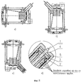
Сущность технического решения поясняется нижеследующим описанием и прилагаемой фигурой. На Фиг.1 показан заливной криостат в разрезе: а) и в) при его работе входным окном в бок - при ориентации криостата входным окном в вертикальном положении относительно горизонта; б) при его работе входным окном вниз - при ориентации криостата входным окном в горизонтальном положении относительно горизонта; г) при его работе входным окном вверх при ориентации криостата входным окном в горизонтальном положении относительно горизонта; где 1 - дренажная трубка, 2 - заглушка, 3 - уплотнительная прокладка, 4 - втулка, 5 - шайба, 6 - баллон для сжиженного газа.The essence of the technical solution is illustrated by the following description and the attached figure. Figure 1 shows the filler cryostat in the context of: a) and c) during its operation by the input window to the side - when the cryostat is oriented by the input window in a vertical position relative to the horizon; b) when it is operated with the input window down, when the cryostat is oriented with the input window in a horizontal position relative to the horizon; d) during its operation, the input window is up when the cryostat is oriented by the input window in a horizontal position relative to the horizon; where 1 is a drainage tube, 2 is a plug, 3 is a gasket, 4 is a sleeve, 5 is a washer, 6 is a cylinder for liquefied gas.
Достижение указанного технического результата при использовании предлагаемого криостата в случае сравнения его с первым из приведенных аналогов базируется на его конструктивном выполнении, обеспечивающем его работу при любой пространственной ориентации относительно горизонта без выливания жидкого азота в полость с размещенным фотоприемником.Achieving the specified technical result when using the proposed cryostat in the case of comparing it with the first of the above analogues is based on its constructive implementation, which ensures its operation with any spatial orientation relative to the horizon without pouring liquid nitrogen into the cavity with the photodetector placed.
Достижение указанного технического результата при использовании предлагаемого криостата в случае сравнения его с ближайшим аналогом базируется на особенностях конструктивного выполнения криостата, позволяющих осуществлять устранение нарушения рабочего температурного режима охлаждаемого фотоприемника, стабилизацию рабочей температуры фотоприемника, расположенного на охлаждаемой платформе.The achievement of the specified technical result when using the proposed cryostat in the case of comparing it with the closest analogue is based on the design features of the cryostat, allowing to eliminate violations of the operating temperature of the cooled photodetector, stabilizing the operating temperature of the photodetector located on the cooled platform.
Указанные конструктивные особенности заключаются в том, что в криостате с рабочей камерой и баллоном для сжиженного газа 6, на котором в рабочей камере смонтирована охлаждаемая платформа, баллон для сжиженного газа 6 снабжен дренажной трубкой 1 для выхода паров выкипающего газа (см. Фиг.1) за пределы криостата на атмосферу. Дренажная трубка 1 выполнена с возможностью размещения ее холодного конца вблизи охлаждаемой платформы в области скопления паров выкипающего газа, образующейся при ориентации криостата входным окном в бок (см. Фиг.1, а) и в)), входное окно ориентировано вертикально), входным окном вверх (см. Фиг.1, г)), входное окно ориентировано горизонтально), и промежуточных положениях, кроме положения входным окном вниз (см. Фиг.1, б)), а теплого конца - с возможностью выхода за пределы баллона для сжиженного газа 6 и, в частности, за пределы криостата.The indicated design features are that in a cryostat with a working chamber and a cylinder for liquefied gas 6, on which a cooled platform is mounted in the working chamber, the cylinder for liquefied gas 6 is equipped with a drain pipe 1 for the exit of vapors of boiling gas (see Figure 1) beyond the limits of the cryostat to the atmosphere. The drainage tube 1 is configured to place its cold end near the cooled platform in the area of accumulation of boiling-gas vapors generated when the cryostat is oriented with the entrance window to the side (see Fig. 1, a) and c)), the entrance window is oriented vertically), the entrance window up (see Fig. 1, d)), the inlet window is oriented horizontally), and in intermediate positions, except for the position of the inlet window down (see Fig. 1, b)), and the warm end - with the possibility of going beyond the cylinder for liquefied gas 6 and, in particular, outside the cryostat.
В общем случае выполнения (см. Фиг.1, а)-г)) заявляемый заливной криостат для приемника инфракрасного излучения содержит корпус с входным окном, рабочую камеру с охлаждаемой платформой, заливной узел криостатирования охлаждаемой платформы в виде баллона для сжиженного газа, дренажную трубку для выхода паров выкипающего газа. Рабочая камера с охлаждаемой платформой, заливной узел криостатирования охлаждаемой платформы в виде баллона для сжиженного газа размещены во внутреннем объеме криостата, ограничиваемом корпусом. Охлаждаемая платформа размещена напротив входного окна криостата и смонтирована на баллоне для сжиженного газа 6. Баллон для сжиженного газа 6 снабжен дренажной трубкой 1 для выхода паров выкипающего газа. Дренажная трубка 1 выполнена с возможностью размещения ее холодного конца вблизи охлаждаемой платформы в области скопления паров выкипающего газа, образующейся при ориентации криостата входным окном относительно горизонта в горизонтальном (см. Фиг.1, г)) - входным окном вверх, вертикальном (см. Фиг.1, а) и в)) - входным окном в бок и промежуточных положениях, кроме положения входным окном вниз (см. Фиг. б)), а теплого конца - с возможностью выхода за пределы баллона для сжиженного газа 6.In the General case of execution (see Figure 1, a) -d)), the inventive filling cryostat for an infrared radiation receiver comprises a housing with an inlet window, a working chamber with a cooled platform, a filling cryostat assembly of the cooled platform in the form of a cylinder for liquefied gas, a drainage tube for the release of boiling gas vapors. The working chamber with the cooled platform, the filling unit for cryostatization of the cooled platform in the form of a cylinder for liquefied gas, are placed in the internal volume of the cryostat, limited by the housing. The cooled platform is located opposite the entrance window of the cryostat and mounted on a cylinder for liquefied gas 6. The cylinder for liquefied gas 6 is equipped with a drain pipe 1 for the exit of vapors of boiling gas. The drainage tube 1 is configured to place its cold end near the cooled platform in the area of accumulation of boiling-gas vapor, which is formed when the cryostat is oriented by the inlet window relative to the horizon in horizontal (see Fig. 1, d)) - inlet window up, vertical (see Fig. .1, a) and c)) - the inlet window to the side and intermediate positions, except for the position of the inlet window down (see Fig. B)), and the warm end - with the possibility of going beyond the cylinder for liquefied gas 6.
Корпус снабжен передним фланцем, в котором выполнено входное окно, напротив которого расположена охлаждаемая платформа. Охлаждаемая платформа, смонтированная на баллоне для сжиженного газа 6, выполнена соосно с входным окном криостата. Кроме того, другие конструктивные элементы криостата, в частности, баллон для сжиженного газа 6, корпус криостата выполнены также соосно.The housing is equipped with a front flange, in which an input window is made, opposite which there is a cooled platform. The cooled platform mounted on the cylinder for liquefied gas 6 is made coaxially with the entrance window of the cryostat. In addition, other structural elements of the cryostat, in particular, a cylinder for liquefied gas 6, the cryostat body is also made coaxially.
В криостате баллон для сжиженного газа 6, в частности, снабжен заливной горловиной из коаксиально расположенных трубок (см. Фиг.1, д)), теплый конец дренажной трубки 1, реализованный с возможностью выхода за пределы баллона для сжиженного газа 6 и, в том числе, за пределы криостата, выведен коаксиально через заливную горловину (см. Фиг.1, д)). Дренажная трубка 1 для выхода паров выкипающего газа - азота выполнена из стали 12Х18Н10Т, размер, мм: ⌀3×0,2. Дренажная трубка 1 вварена во внутреннем объеме криостата с возможностью ее фиксации к конструктивным элементам криостата, расположенным во внутреннем объеме, например, к корпусу контейнера под сорбент (см. Фиг.1, а)-г)).In the cryostat, the cylinder for liquefied gas 6, in particular, is equipped with a filler neck from coaxially arranged tubes (see Fig. 1, e)), the warm end of the drainage tube 1, which is configured to extend beyond the cylinder for liquefied gas 6 and, in that number, outside the cryostat, displayed coaxially through the filler neck (see Figure 1, e)). Drain pipe 1 for the exit of vapors of boiling gas - nitrogen is made of steel 12X18H10T, size, mm: ⌀3 × 0.2. The drainage tube 1 is welded into the inner volume of the cryostat with the possibility of its fixation to the structural elements of the cryostat located in the inner volume, for example, to the container body under the sorbent (see Figure 1, a) -d)).
Баллон для сжиженного газа 6 снабжен фторопластовой заглушкой 2 (см. Фиг.1, д)), установленной в заливной горловине криостата, препятствующий вытеканию сжиженного газа - азота через заливную горловину, теплый конец дренажной трубки 1 выведен через заглушку 2 сквозным образом. Кроме того, в заливной горловине для герметизации установлена уплотнительная прокладка 3 (см. Фиг.1, д)). Уплотнительная прокладка 3 выполнена из резины. Также заливная горловина снабжена навинчиваемой на нее медной втулкой 4 для уплотнения резиновой прокладки и снабжена дополнительно шайбой 5. При этом шайба 5 и уплотнительная прокладка 3 установлены между навинчиваемой на заливную горловину втулкой и фторопластовой заглушкой 2 (см. Фиг.1, д)).The cylinder for liquefied gas 6 is equipped with a fluoroplastic plug 2 (see Figure 1, e)) installed in the filler neck of the cryostat, which prevents the flow of liquefied gas - nitrogen through the filler neck, the warm end of the drainage tube 1 is removed through the cap 2 in a through way. In addition, in the filler neck for sealing, a
Баллон для сжиженного газа 6 выполнен из меди. Использование данного материала преследует цель стабилизации температуры криостатирования относительно охлаждаемой платформы по мере выкипания жидкого азота при работе криостата в положении входным окном вверх.The cylinder for liquefied gas 6 is made of copper. The use of this material is aimed at stabilizing the temperature of the cryostat relative to the cooled platform as liquid nitrogen boils while the cryostat is in the up position with the inlet window.
Таким образом, приведенное конструктивное выполнение криостата обеспечивает возможность его работы не только в горизонтальном положении - входным окном вбок, в вертикальном положении - входным окном вниз и во всех промежуточных положениях между ними, что характерно для прототипа, но также обеспечивает возможность его работы в вертикальном положении - входным окном вверх и во всех промежуточных положениях от горизонтального до вертикального положения - входным окном вверх. Предлагаемый заливной криостат «держит» жидкий азот до полного его выкипания во всех указанных положениях не менее 9 часов при емкости баллона для сжиженного газа около 210 мл. Масса криостата составляет примерно 1,9 кг. Время удержания вакуума - не менее 12 лет.Thus, the above structural design of the cryostat provides the possibility of its operation not only in a horizontal position - with the entrance window to the side, in a vertical position - with the entrance window down and in all intermediate positions between them, which is typical for the prototype, but also provides the possibility of its operation in the vertical position - the input window up and in all intermediate positions from horizontal to vertical position - the input window up. The proposed filling cryostat “holds” liquid nitrogen until it boils completely in all the indicated positions for at least 9 hours with a cylinder capacity for liquefied gas of about 210 ml. The mass of the cryostat is approximately 1.9 kg. Vacuum retention time - at least 12 years.
Криостат используют следующим образом.The cryostat is used as follows.
После предварительной проверки криостата на герметичность на охлаждаемой платформе напротив входного окна в корпусе криостата устанавливают, например, гибридную микросхему матричного или линейчатого фотоприемного устройства, герметизируют передний фланец с входным окном. В контейнер под сорбент загружают сорбент - активированный уголь. Осуществляют его заглушку и герметизацию. Устанавливают криостат на откачной пост. Криостат откачивают до рабочего уровня вакуума, герметизируют путем откусывания штенгеля. Далее готовый к работе криостат устанавливают в прибор, например, тепловизор, в котором он является составной частью, необходимой для работы прибора.After a preliminary check of the cryostat for leaks on the cooled platform opposite the input window in the cryostat housing, for example, a hybrid microcircuit of a matrix or line photodetector is installed, and the front flange with the input window is sealed. A sorbent - activated carbon is loaded into a container under the sorbent. Carry out its cap and sealing. Install the cryostat on the pumping station. The cryostat is pumped out to a working vacuum level, sealed by biting off the ram. Next, a ready-to-use cryostat is installed in the device, for example, a thermal imager, in which it is an integral part necessary for the operation of the device.
Для охлаждения (80 К) гибридной сборки матрицы фоточувствительных элементов и кремниевого мультиплексора в баллон для сжиженного газа 6 узла криостатирования охлаждаемой платформы заливают азот (см. Фиг.1). Осуществляют выход на рабочий режим. Предлагаемый криостат гарантированно обеспечивает при расходе 210 мл жидкого азота 9 часов непрерывной работы прибора после выхода на рабочий режим, как показано на практике.For cooling (80 K) of the hybrid assembly of the photosensitive elements matrix and the silicon multiplexer, nitrogen is filled into the liquefied gas cylinder 6 of the cryostat assembly of the cooled platform (see Figure 1). Exit to the operating mode. The proposed cryostat is guaranteed to provide at a flow rate of 210 ml of liquid nitrogen 9 hours of continuous operation of the device after reaching the operating mode, as shown in practice.
Claims (9)
Priority Applications (1)
| Application Number | Priority Date | Filing Date | Title |
|---|---|---|---|
| RU2012107038/28A RU2492435C9 (en) | 2012-02-27 | 2012-02-27 | Filler cryostat for infrared detector |
Applications Claiming Priority (1)
| Application Number | Priority Date | Filing Date | Title |
|---|---|---|---|
| RU2012107038/28A RU2492435C9 (en) | 2012-02-27 | 2012-02-27 | Filler cryostat for infrared detector |
Publications (2)
| Publication Number | Publication Date |
|---|---|
| RU2492435C1 RU2492435C1 (en) | 2013-09-10 |
| RU2492435C9 true RU2492435C9 (en) | 2013-12-20 |
Family
ID=49164969
Family Applications (1)
| Application Number | Title | Priority Date | Filing Date |
|---|---|---|---|
| RU2012107038/28A RU2492435C9 (en) | 2012-02-27 | 2012-02-27 | Filler cryostat for infrared detector |
Country Status (1)
| Country | Link |
|---|---|
| RU (1) | RU2492435C9 (en) |
Citations (6)
| Publication number | Priority date | Publication date | Assignee | Title |
|---|---|---|---|---|
| SU180383A1 (en) * | А. И. тницкий, А. Г. НадольникЪв, Р. М. Арамович | CRYOSTAT FOR RADIATION RECEIVERS | ||
| US5049751A (en) * | 1989-12-06 | 1991-09-17 | Fujitsu Limited | Infrared rays detecting apparatus |
| RU10857U1 (en) * | 1999-02-03 | 1999-08-16 | Закрытое акционерное общество "Матричные технологии" | CRYOSTAT FOR IR RADIATION RECEIVERS |
| RU11313U1 (en) * | 1999-04-22 | 1999-09-16 | Закрытое акционерное общество "Матричные технологии" | Cryostat for infrared receivers |
| RU64744U1 (en) * | 2007-04-05 | 2007-07-10 | Открытое акционерное общество "Московский завод "САПФИР" | CRYOSTAT FOR INFRARED RADIATION RECEIVER |
| RU2406946C1 (en) * | 2009-08-12 | 2010-12-20 | Учреждение Российской академии наук Институт физики полупроводников им. А.В. Ржанова Сибирского отделения РАН (ИФП СО РАН) | Cryostat for infrared radiation receiver |
-
2012
- 2012-02-27 RU RU2012107038/28A patent/RU2492435C9/en not_active IP Right Cessation
Patent Citations (6)
| Publication number | Priority date | Publication date | Assignee | Title |
|---|---|---|---|---|
| SU180383A1 (en) * | А. И. тницкий, А. Г. НадольникЪв, Р. М. Арамович | CRYOSTAT FOR RADIATION RECEIVERS | ||
| US5049751A (en) * | 1989-12-06 | 1991-09-17 | Fujitsu Limited | Infrared rays detecting apparatus |
| RU10857U1 (en) * | 1999-02-03 | 1999-08-16 | Закрытое акционерное общество "Матричные технологии" | CRYOSTAT FOR IR RADIATION RECEIVERS |
| RU11313U1 (en) * | 1999-04-22 | 1999-09-16 | Закрытое акционерное общество "Матричные технологии" | Cryostat for infrared receivers |
| RU64744U1 (en) * | 2007-04-05 | 2007-07-10 | Открытое акционерное общество "Московский завод "САПФИР" | CRYOSTAT FOR INFRARED RADIATION RECEIVER |
| RU2406946C1 (en) * | 2009-08-12 | 2010-12-20 | Учреждение Российской академии наук Институт физики полупроводников им. А.В. Ржанова Сибирского отделения РАН (ИФП СО РАН) | Cryostat for infrared radiation receiver |
Also Published As
| Publication number | Publication date |
|---|---|
| RU2492435C1 (en) | 2013-09-10 |
Similar Documents
| Publication | Publication Date | Title |
|---|---|---|
| CN107614990B (en) | Cryostat with first and second helium vessels liquid-tightly separated from each other at least in a lower region | |
| KR101822263B1 (en) | Low thermal liquid storage tank with a detachable cryocooler | |
| CN102971594A (en) | Method and apparatus for controlling temperature in a cryocooled cryostat using static and moving gas | |
| ES2520643T3 (en) | A procedure and a heat pipe construction apparatus | |
| GB2492645A8 (en) | Cryostat | |
| CA2663397A1 (en) | Stripping absorption module | |
| US2985356A (en) | Pumping device | |
| ES2393286T3 (en) | Procedure for the distillation of a starting material, and installation to perform said procedure | |
| CN103697647A (en) | Vacuum low-temperature thermostat | |
| RU2492435C9 (en) | Filler cryostat for infrared detector | |
| US3225825A (en) | Cold trap | |
| RU2009147441A (en) | CAPACITOR RADIATOR | |
| US3688514A (en) | Cryostats | |
| KR100983111B1 (en) | A distiller using multiple-stage column | |
| RU2406946C1 (en) | Cryostat for infrared radiation receiver | |
| SU1698481A1 (en) | Cryogenic adsorption pump | |
| JP6588264B2 (en) | Cryogenic refrigerant supply system | |
| JP5941380B2 (en) | Distillation tower with self-heating and heat insulation effect | |
| CN205287678U (en) | Vacuum silvering rectifier unit | |
| JP5640072B2 (en) | Apparatus and method for introducing materials into a cryogenic system | |
| CN210376204U (en) | A device for liquid helium storage and multi-layer thermal insulation material testing in liquid helium temperature zone | |
| JPH0131285Y2 (en) | ||
| GB2347214A (en) | Ebulliometric device for measuring with high precision a physical parameter of liquid substances | |
| RU2488192C2 (en) | Cryostat for infrared radiation detector | |
| CN216877895U (en) | Rectifying tower |
Legal Events
| Date | Code | Title | Description |
|---|---|---|---|
| TH4A | Reissue of patent specification | ||
| MM4A | The patent is invalid due to non-payment of fees |
Effective date: 20170228 |