RU2484296C2 - Wind-driven power plant - Google Patents
Wind-driven power plant Download PDFInfo
- Publication number
- RU2484296C2 RU2484296C2 RU2011132756/06A RU2011132756A RU2484296C2 RU 2484296 C2 RU2484296 C2 RU 2484296C2 RU 2011132756/06 A RU2011132756/06 A RU 2011132756/06A RU 2011132756 A RU2011132756 A RU 2011132756A RU 2484296 C2 RU2484296 C2 RU 2484296C2
- Authority
- RU
- Russia
- Prior art keywords
- wind
- shaft
- support
- working substance
- pump
- Prior art date
Links
Images
Classifications
-
- Y—GENERAL TAGGING OF NEW TECHNOLOGICAL DEVELOPMENTS; GENERAL TAGGING OF CROSS-SECTIONAL TECHNOLOGIES SPANNING OVER SEVERAL SECTIONS OF THE IPC; TECHNICAL SUBJECTS COVERED BY FORMER USPC CROSS-REFERENCE ART COLLECTIONS [XRACs] AND DIGESTS
- Y02—TECHNOLOGIES OR APPLICATIONS FOR MITIGATION OR ADAPTATION AGAINST CLIMATE CHANGE
- Y02E—REDUCTION OF GREENHOUSE GAS [GHG] EMISSIONS, RELATED TO ENERGY GENERATION, TRANSMISSION OR DISTRIBUTION
- Y02E10/00—Energy generation through renewable energy sources
- Y02E10/70—Wind energy
- Y02E10/728—Onshore wind turbines
-
- Y—GENERAL TAGGING OF NEW TECHNOLOGICAL DEVELOPMENTS; GENERAL TAGGING OF CROSS-SECTIONAL TECHNOLOGIES SPANNING OVER SEVERAL SECTIONS OF THE IPC; TECHNICAL SUBJECTS COVERED BY FORMER USPC CROSS-REFERENCE ART COLLECTIONS [XRACs] AND DIGESTS
- Y02—TECHNOLOGIES OR APPLICATIONS FOR MITIGATION OR ADAPTATION AGAINST CLIMATE CHANGE
- Y02E—REDUCTION OF GREENHOUSE GAS [GHG] EMISSIONS, RELATED TO ENERGY GENERATION, TRANSMISSION OR DISTRIBUTION
- Y02E10/00—Energy generation through renewable energy sources
- Y02E10/70—Wind energy
- Y02E10/74—Wind turbines with rotation axis perpendicular to the wind direction
-
- Y—GENERAL TAGGING OF NEW TECHNOLOGICAL DEVELOPMENTS; GENERAL TAGGING OF CROSS-SECTIONAL TECHNOLOGIES SPANNING OVER SEVERAL SECTIONS OF THE IPC; TECHNICAL SUBJECTS COVERED BY FORMER USPC CROSS-REFERENCE ART COLLECTIONS [XRACs] AND DIGESTS
- Y02—TECHNOLOGIES OR APPLICATIONS FOR MITIGATION OR ADAPTATION AGAINST CLIMATE CHANGE
- Y02P—CLIMATE CHANGE MITIGATION TECHNOLOGIES IN THE PRODUCTION OR PROCESSING OF GOODS
- Y02P80/00—Climate change mitigation technologies for sector-wide applications
- Y02P80/10—Efficient use of energy, e.g. using compressed air or pressurized fluid as energy carrier
Abstract
Description
Изобретение относится к области ветроэнергетики, а именно к использованию энергии ветра для получения электрической или механической энергии.The invention relates to the field of wind energy, and in particular to the use of wind energy to produce electrical or mechanical energy.
Аналогичные технические решения известны, например, насосная установка (см. SU 1453077 А1, кл. F03B 13/12, 23.01.1989), которая содержит погруженную под уровень воды опору и прикрепленный к ней при помощи шарнира вертикальный стержень с поплавком, кинематически связанный с рабочей камерой переменного объема, имеющей обратные клапаны. Стержень снабжен упорами и имеет расположенный под шарниром участок. Поплавок выполнен с удельной плотностью, близкой к плотности воды, и установлен между упорами с возможностью перемещения относительно стержня. Рабочая камера выполнена в виде двух сильфонных патрубков, соединенных между собой при помощи пластины, прикрепленной к нижнему участку стержня, и нагружена на напорную магистраль. К недостаткам установки относятся низкий КПД (коэффициент полезного действия) и сложность конструкции.Similar technical solutions are known, for example, a pumping unit (see SU 1453077 A1, class F03B 13/12, 01/23/1989), which contains a support submerged under the water level and attached to it by a hinge with a vertical rod with a float kinematically connected with a working chamber of variable volume having check valves. The rod is equipped with stops and has a section located under the hinge. The float is made with a specific density close to the density of water, and is installed between the stops with the possibility of movement relative to the rod. The working chamber is made in the form of two bellows nozzles interconnected by means of a plate attached to the lower portion of the rod, and is loaded onto the pressure line. The disadvantages of the installation include low efficiency (efficiency) and design complexity.
Известно устройство, в котором реализована идея качающегося щита, на который давит воздушный поток. Это устройство описано в патенте "Ветровая энергетическая установка" (см. патент RU 2277642, F03D 3/00, 10.01.2006), который принят за прототип. В этой установке энергия ветра используется без преобразования его во вращение. Ветровая энергетическая установка содержит опору и стержень, прикрепленный одним окончанием к опоре при помощи шарнирного соединения. Стержень соединен с устройством (условно называемое "парусом"), которое обладает поверхностной площадью и способностью сопротивляться ветровому потоку, а также в автоматическом и (или) ручном режиме может менять величину своей поверхностной площади.A device is known in which the idea of a swinging shield is realized, on which an air stream presses. This device is described in the patent "Wind power installation" (see patent RU 2277642, F03D 3/00, 01/10/2006), which is adopted as a prototype. In this installation, wind energy is used without converting it into rotation. The wind power installation includes a support and a rod attached at one end to the support using a swivel. The rod is connected to a device (conditionally called a "sail"), which has a surface area and the ability to resist the wind flow, and in automatic and (or) manual mode can change the value of its surface area.
При этом устройство ("парус"), сопротивляясь ветровому потоку, осуществляет отклонение стержня относительно шарнирного соединения при воздействии на это устройство ветрового потока. Стержень также соединен с компенсатором, удерживающим этот стержень в исходном вертикальном положении при отсутствии воздействия ветрового потока на установку и возвращающим стержень в исходное вертикальное положение после окончания воздействия ветрового потока на ветровую энергетическую установку.In this case, the device ("sail"), resisting the wind flow, carries out the deflection of the rod relative to the swivel when exposed to this device wind flow. The rod is also connected to a compensator that holds this rod in its original vertical position in the absence of the influence of the wind flow on the installation and returns the rod to its original vertical position after the end of the effect of the wind flow on the wind power installation.
Недостатком прототипа является низкий КПД, обусловленный тем, что мачта на обратном ходе не вырабатывает полезной энергии. Кроме того, в компенсаторе теряется около 50% энергии, получаемой мачтой от ветрового потока, а в гидронасосе - 25% энергии. Если максимальный коэффициент использования энергии ветра (КИЭВ) парусной установки не превышает 0,197, то в прототипе он меньше 0,197*0,5*0,75=0.074. Кроме того, в предлагаемом устройстве конкретно не решены вопросы ориентирования "паруса" относительно направления ветрового потока, переход на режим флюгера (при обратном ходе мачты) и установка активного "паруса". Для внедрения известного устройства необходимо еще решать вопросы управления для циклической работы "паруса".The disadvantage of the prototype is low efficiency, due to the fact that the mast on the return stroke does not produce useful energy. In addition, about 50% of the energy received by the mast from the wind flow is lost in the compensator, and 25% of the energy in the hydraulic pump. If the maximum coefficient of utilization of wind energy (KIEV) of a sailing installation does not exceed 0.197, then in the prototype it is less than 0.197 * 0.5 * 0.75 = 0.074. In addition, the proposed device has not specifically resolved issues of orientation of the "sail" relative to the direction of the wind flow, the transition to the wind vane mode (with the reverse course of the mast) and the installation of the active "sail". To implement the known device, it is still necessary to solve control issues for the cyclic operation of the "sail".
Технической задачей является создание устройства, способного преобразовывать кинетическую энергию ветрового потока при надежной циклической работе независимо от его направления, в кинетическую энергию механических возвратно-поступательных и вращательных движений, с последующим преобразованием ее в электрическую или механическую энергию.The technical task is to create a device capable of converting the kinetic energy of the wind flow with reliable cyclic operation, regardless of its direction, into the kinetic energy of mechanical reciprocating and rotational movements, followed by its conversion into electrical or mechanical energy.
Технический результат заявляемой ветровой энергетической установки по сравнению с прототипом заключается в обеспечении более высокого КПД, надежной и безопасной работе по четкому очевидному алгоритму даже при порывистых, шквальных и переменных ветровых потоках.The technical result of the inventive wind power installation compared to the prototype is to provide higher efficiency, reliable and safe operation according to a clear obvious algorithm, even with gusty, heavy and variable wind flows.
Этот результат обеспечивается за счет того, что ветровая энергетическая установка содержит опору, стержень, прикрепленный одним окончанием к опоре, а другим соединенный с устройством, которое обладает поверхностной площадью и способностью сопротивляться ветровому потоку, насос с поршнем, который имеет впускные и выпускные клапаны, соединенные с питающей и напорной магистралями. При этом стержень представляет собой вращающийся вал, который закреплен в верхнем и нижнем опорных стаканах с подшипниками, нижний опорный стакан соединен с поверхностью опоры, а верхний соединен с конструктивным узлом, обеспечивающим вертикальное положение вала. На верхнюю часть вала в качестве устройства, способного сопротивляться ветровому потоку, закреплено лопастное карусельное ветроколесо, а ниже на вал симметрично насажена прямоугольная многосторонняя призма с четным числом сторон, к каждой боковой стороне которой прикреплен силовой узел, выполненный в виде мембраны и насоса. Поршни насосов подсоединены к соответствующим мембранам, причем противоположные мембраны попарно связаны штоками, а впускные и выпускные клапаны насосов подсоединены к общим напорной и питающей магистралям установки, проходящими внутри вала и переходящими на неподвижную опору через ротационное соединение, установленное на ней.This result is achieved due to the fact that the wind power installation contains a support, a rod attached with one end to the support, and the other connected to a device that has a surface area and the ability to resist wind flow, a pump with a piston, which has inlet and outlet valves connected with supply and pressure lines. In this case, the rod is a rotating shaft, which is fixed in the upper and lower bearing cups with bearings, the lower bearing cup is connected to the surface of the support, and the upper one is connected to a structural unit that ensures the vertical position of the shaft. As a device capable of resisting the wind flow, a rotary rotary wind wheel is mounted on the upper part of the shaft, and a rectangular multilateral prism with an even number of sides is symmetrically mounted on the shaft below, to each side of which there is a power unit made in the form of a membrane and a pump. The pistons of the pumps are connected to the corresponding membranes, and the opposite membranes are connected in pairs by rods, and the inlet and outlet valves of the pumps are connected to the common pressure and supply lines of the installation, passing inside the shaft and passing to the fixed support through the rotary connection installed on it.
При этом вход питающей магистрали соединен с источником рабочего вещества, а выход напорной магистрали подсоединен к аккумулятору рабочего вещества, причем к выходу последнего подключен напорный трубопровод, соединяющий ее с потребителем.In this case, the inlet of the supply line is connected to the source of the working substance, and the outlet of the pressure line is connected to the accumulator of the working substance, and the outlet pipe connecting it to the consumer is connected to the outlet of the latter.
К аккумулятору рабочего вещества может быть подключен вход соответствующего двигателя, а его выход подключен к питающей магистрали через источник рабочего вещества, вал этого двигателя нагружен на генератор, к выходу которого подключены электроаккумулятор и инвертор с нагрузкой переменного тока.The input of the corresponding motor can be connected to the accumulator of the working substance, and its output is connected to the supply line through the source of the working substance, the shaft of this engine is loaded on a generator, to the output of which an electric accumulator and an inverter with an AC load are connected.
На фиг.1 изображен общий вид ветровой энергетической установки.Figure 1 shows a General view of a wind power plant.
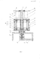
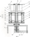
На фиг.2 изображена конструкция ветровой энергетической установки в разрезе, вид сбоку.Figure 2 shows the construction of a wind power installation in section, side view.
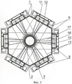
На фиг.3 изображена конструкция ветровой энергетической установки в разрезе, вид сверху.Figure 3 shows the construction of a wind power plant in the context, top view.
Ветровая энергетическая установка представляет собой прямоугольную многостороннюю призму 1 с четным числом сторон и с симметрично по центру расположенным валом 2. Вал 2 установки закреплен в верхнем 3 и нижнем 4 опорных стаканах с подшипниками. Нижний опорный стакан 4 жестко соединен с поверхностью опоры 5, на которой располагается ветровая энергетическая установка. Опорой 5 может быть поверхность земли или крыша здания. Верхний опорный стакан 3 соединен с конструктивным узлом 6, обеспечивающим жесткое, строго вертикальное положение вала 2. В качестве конструктивного узла 6 могут быть применены, например, стальные растяжки, показанные на фиг.1.The wind power installation is a rectangular
На каждую боковую сторону призмы 1 закреплен силовой узел 7, состоящий из мембраны 8, насоса 9 с поршнем 10 и выпускными 11 и впускными клапанами 12. Мембрана 8 также соединена со штоками 13, которые связаны с мембраной 8 силового узла 7 на противоположной стороне призмы 1.A
Применение штоков 13 вместо общепринятых в этом случае пружин повышает КПД установки (при движении поршня 10 и мембраны 8) и технологичность конструкции.The use of
Для того чтобы ветровой поток воздействовал на все стороны призмы 1, ветровая энергетическая установка снабжена ветроколесом 14. Оно преобразует кинетическую энергию ветрового потока 15 в кинетическую энергию механического вращательного движения. Практически в качестве ветроколеса установки могут применяться любые известные типы ветроколес с вертикальной осью вращения ротора. Однако в сочетании с предлагаемой конструкцией установки, наиболее оправдано применение лопастного карусельного ветроколеса с вертикальной осью вращения (общей для всей установки). Оно наиболее просто в эксплуатации, его конструкция обеспечивает максимальный момент при запуске установки и позволяет отказаться от системы ориентации по направлению ветра. Из-за большого геометрического заполнения лопастное ветроколесо обладает большим крутящим моментом, который не уменьшается с увеличением нагрузки. Необходимо отметить, что сила ветрового потока 15, действующая на мембраны 8 призмы 1 и лопасти ветроколеса 14, пропорциональна квадрату скорости ветрового потока, что в перспективе облегчит синхронизацию оборотов установки с эффективной работой насосов 9 за счет регулирования парусности лопастей ветроколеса 14.In order for the wind flow to affect all sides of the
Помимо этого, ветровая энергетическая установка содержит питающую 16 и напорную 17 магистрали, которые могут быть наполнены газовым или жидким рабочим телом. Питающая магистраль соединена с впускными клапанами 12 насосов 9, а напорная магистраль соединена с выпускными клапанами 11 этих насосов. Для передачи рабочего тела по напорной 17 и питающей 16 магистралям с вращающейся части установки на опору 5 используется ротационное соединение 18, установленное на опоре.In addition, the wind power installation contains a
Ветровая энергетическая установка (по фиг.1-3) работает следующим образом.Wind power installation (Fig.1-3) works as follows.
При воздействии ветрового потока 15 на внешнюю мембрану 8 силового узла 7, она движется параллельно начальному положению к валу установки 2, преодолевая сопротивление поршня 10 соответствующего насоса 9, вытесняя из рабочей камеры этого насоса рабочее тело в напорную магистраль 17 через выпускной клапан 11 и смещая противоположную внешнюю мембрану 8 от вала 2 с помощью штоков 13, создавая разрежение в пустой противоположной рабочей камере насоса 9. После окончания воздействия ветрового потока 15 на мембрану 8, когда она будет смещена при повороте призмы 1, штоки 13 возвращают ее в исходное положение, заполняя через впускной клапан 12 перекачиваемое рабочее тело из питающей магистрали 16 под воздействием атмосферного давления. При этом под действием ветрового потока 15 происходит поворот призмы 1 с помощью ветроколеса 14 и под ветровой поток 15 подставляется следующий силовой узел 7 - мембрана 8 с насосом 9 и его поршнем 10. Опять происходит изменение объема рабочих камер насоса 9 (вытеснение рабочего тела поршнем 10) через клапаны 11 в напорную магистраль 17 и нагнетание через клапаны 12 в рабочую камеру противоположного насоса 9 рабочего тела, которое в данный момент отсутствует в его камере. Рабочее тело по питающей 16 и напорной 17 магистралям передается с вращающейся части установки на опору 5 через ротационное соединение 18.When the
Величина амплитуды рабочего хода мембран 8 и поршня 10, а также объем рабочих камер каждого насоса 9 определяется конструкцией силового узла 7.The magnitude of the amplitude of the stroke of the
Коэффициент усиления давления рабочего тела в напорной магистрали 17 зависит от соотношения площадей мембраны S1 и поршня S2, что позволяет расширить рабочий диапазон скоростей ветрового потока 15.The gain of the pressure of the working fluid in the
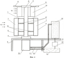
На фиг.4 изображена конструкция ветровой энергетической установки для совершения механической работы.Figure 4 shows the design of a wind power plant for performing mechanical work.
Ветровая энергетическая установка (по фиг.2 и 3) устанавливается вблизи источника рабочего вещества 19 (например - водоема), расположенного на уровне земли или ниже. При этом питающая магистраль 16 соединяется с указанным источником 19, а напорная магистраль 17 соединяется с аккумулятором рабочего вещества 20, сооруженным на возвышении над уровнем земли (например, водонапорная башня, верхнее помещение жилого, административного или заводского здания и т.п.). Выход аккумулятора рабочего вещества 20 через напорный трубопровод 21 подключен к потребителю рабочего вещества 22 под давлением.A wind power installation (in FIGS. 2 and 3) is installed near the source of the working substance 19 (for example, a reservoir) located at or below ground level. In this case, the
Ветровая энергетическая установка для совершения механической работы (по фиг.4) работает следующим образом.Wind power installation for mechanical work (Fig.4) works as follows.
Под воздействием ветрового потока 15 призма 1 с помощью ветроколеса 14 будет вращаться, а элементы силовых узлов 7 будут совершать возвратно-поступательные движения, вытесняя перекачиваемую жидкость из питающей магистрали 16 в напорную магистраль 17 через ротационное соединение 18.Under the influence of the
Таким образом, установка будет перекачивать жидкость из источника рабочего вещества 19 в аккумулятор рабочего вещества 20, накапливать ее (создавая потенциальную энергию). В качестве потребителя для получения электроэнергии может использоваться, например, турбогенератор. Потенциальная энергия рабочего вещества (жидкости), накопленная в аккумуляторе рабочего вещества 20, преобразуется в электрическую энергию путем направления рабочего вещества по напорному трубопроводу 21 к потребителю 22 (например, на вращающиеся лопасти турбогенератора, вырабатывающего электроэнергию). Далее рабочее вещество направляется в источник 19.Thus, the installation will pump fluid from the source of the working
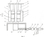
На фиг.5 изображена ветровая энергетическая установка для выработки электроэнергии.Figure 5 shows a wind power plant for generating electricity.
В установке (по фиг.2 и 3) к напорной магистрали 17 через аккумулятор рабочего вещества 20 подключен вход двигателя 23, например, гидравлического или пневматического, а его выход подключен через источник рабочего вещества 19 к питающей магистрали 16. Источник рабочего вещества может содержать, например, жидкость, масло, эмульсию и т.п. Двигатель 23 нагружен на вал генератора 24, например, постоянного тока. Кроме того, к выходу генератора 24 подключен электроаккумулятор 25, позволяющий накопить электроэнергию при отсутствии ветрового потока 15. Выход генератора 24 также подсоединен к инвертору 26, формирующему на выходе переменный ток необходимой частоты, напряжения и фазности.In the installation (Fig.2 and 3) to the
Ветровая энергетическая установка (по фиг.5) работает следующим образом.Wind power installation (Fig.5) works as follows.
При воздействии ветрового потока 15 призма 1 с помощью ветроколеса 14 будет вращаться, а элементы силовых узлов 7 будут совершать возвратно-поступательные движения, вытесняя перекачиваемую жидкость из питающей магистрали 16 в напорную магистраль 17 через ротационное соединение 18.Under the influence of the
Таким образом, жидкость (газ или воздух) нагнетается по напорной магистрали 17 в гидравлический (пневматический) двигатель 24 через аккумулятор рабочего вещества 20, поддерживающий определенный заданный уровень давления. При наличии рабочего тела (жидкости, газа или воздуха) в аккумуляторе рабочего вещества 20, оно начинает воздействовать на двигатель 24, вызывая тем самым, вращение его вала. При этом рабочее тело, содержащееся в источнике рабочего вещества 19, находится также в напорной, питающей магистралях и аккумуляторе рабочего вещества 20. Поскольку двигатель 23 нагружен на вал генератора 24 последний будет вырабатывать электрическую энергию. Электроэнергия будет вырабатываться до тех пор, пока двигатель 23 будет осуществлять вращение вала генератора 24 с учетом заданной электрической нагрузки, т.е. пока давление в аккумуляторе рабочего вещества 20 поддерживается на определенном уровне. Таким образом, кинетическая энергия ветрового потока 15 превращается в энергию электрического тока и появляется возможность накопить в аккумуляторах 20 и 25 потенциальную энергию, необходимую в случае длительного штилевого характера ветрового потока 15.Thus, the liquid (gas or air) is pumped along the
При наличии связи ветровой энергетической установки с промышленной сетью или при наличии нагрузки переменного тока к генератору 24 и электроаккумулятору 25 подключен инвертор 26, формирующий на выходе переменный ток необходимой частоты, напряжения и фазности.If there is a connection between the wind power installation and the industrial network, or if there is an AC load, an
Таким образом, предлагаемая ветровая энергетическая установка позволяет по сравнению с прототипом обеспечить более высокий КПД, надежную и безопасную работу по четкому очевидному алгоритму даже при порывистых, шквальных и переменных ветровых потоках. В связи с этим ветровая энергетическая установка имеет более широкую область применения.Thus, the proposed wind power installation allows, in comparison with the prototype, to provide higher efficiency, reliable and safe operation according to a clear obvious algorithm even with gusty, heavy and variable wind flows. In this regard, the wind power installation has a wider scope.
Claims (3)
Priority Applications (1)
| Application Number | Priority Date | Filing Date | Title |
|---|---|---|---|
| RU2011132756/06A RU2484296C2 (en) | 2011-08-03 | 2011-08-03 | Wind-driven power plant |
Applications Claiming Priority (1)
| Application Number | Priority Date | Filing Date | Title |
|---|---|---|---|
| RU2011132756/06A RU2484296C2 (en) | 2011-08-03 | 2011-08-03 | Wind-driven power plant |
Publications (2)
| Publication Number | Publication Date |
|---|---|
| RU2011132756A RU2011132756A (en) | 2013-02-10 |
| RU2484296C2 true RU2484296C2 (en) | 2013-06-10 |
Family
ID=48785968
Family Applications (1)
| Application Number | Title | Priority Date | Filing Date |
|---|---|---|---|
| RU2011132756/06A RU2484296C2 (en) | 2011-08-03 | 2011-08-03 | Wind-driven power plant |
Country Status (1)
| Country | Link |
|---|---|
| RU (1) | RU2484296C2 (en) |
Cited By (1)
| Publication number | Priority date | Publication date | Assignee | Title |
|---|---|---|---|---|
| RU2689660C1 (en) * | 2018-07-25 | 2019-05-28 | Юлий Борисович Соколовский | Wind-driven power plant |
Citations (6)
| Publication number | Priority date | Publication date | Assignee | Title |
|---|---|---|---|---|
| SU1132795A3 (en) * | 1981-04-16 | 1984-12-30 | Бернхард Йест (ФРГ) | Installation for using wind energy |
| SU1753018A2 (en) * | 1989-11-09 | 1992-08-07 | В.Г.Иванов | Windmill electric generating unit |
| RU2030629C1 (en) * | 1992-06-04 | 1995-03-10 | Николай Всеволодович Лисовский | Wind-pump plant |
| RU2277642C2 (en) * | 2004-06-01 | 2006-06-10 | Валерий Викторович Мурашевский | Wind power plant |
| UA86628C2 (en) * | 2007-01-26 | 2009-05-12 | Общество С Ограниченной Ответственностью "Проектно-Конструкторское И Технологическое Бюро "Конкорд" | Windmill |
| AR070899A1 (en) * | 2008-03-13 | 2010-05-12 | Gracia Lopez Fernando | SYSTEM AND METHOD FOR CONVERTING THE DYNAMIC ENERGY OF A FLUID |
-
2011
- 2011-08-03 RU RU2011132756/06A patent/RU2484296C2/en not_active IP Right Cessation
Patent Citations (6)
| Publication number | Priority date | Publication date | Assignee | Title |
|---|---|---|---|---|
| SU1132795A3 (en) * | 1981-04-16 | 1984-12-30 | Бернхард Йест (ФРГ) | Installation for using wind energy |
| SU1753018A2 (en) * | 1989-11-09 | 1992-08-07 | В.Г.Иванов | Windmill electric generating unit |
| RU2030629C1 (en) * | 1992-06-04 | 1995-03-10 | Николай Всеволодович Лисовский | Wind-pump plant |
| RU2277642C2 (en) * | 2004-06-01 | 2006-06-10 | Валерий Викторович Мурашевский | Wind power plant |
| UA86628C2 (en) * | 2007-01-26 | 2009-05-12 | Общество С Ограниченной Ответственностью "Проектно-Конструкторское И Технологическое Бюро "Конкорд" | Windmill |
| AR070899A1 (en) * | 2008-03-13 | 2010-05-12 | Gracia Lopez Fernando | SYSTEM AND METHOD FOR CONVERTING THE DYNAMIC ENERGY OF A FLUID |
Cited By (1)
| Publication number | Priority date | Publication date | Assignee | Title |
|---|---|---|---|---|
| RU2689660C1 (en) * | 2018-07-25 | 2019-05-28 | Юлий Борисович Соколовский | Wind-driven power plant |
Also Published As
| Publication number | Publication date |
|---|---|
| RU2011132756A (en) | 2013-02-10 |
Similar Documents
| Publication | Publication Date | Title |
|---|---|---|
| CA2322882C (en) | Extracting power from moving water | |
| US7989973B2 (en) | Fluid-responsive oscillation power generation method and apparatus | |
| US8525365B2 (en) | Device for generating electric energy from a renewable source | |
| US8106527B1 (en) | Hydraulic power generator | |
| US20110030361A1 (en) | Hydrostatic linear wind mill for wind energy harnessing applications | |
| NO20024728L (en) | Wind and wave energy systems | |
| EP3374628B1 (en) | Method for efficiently obtaining mechanical work and/or generating power from fluid flows and apparatus thereof | |
| WO2013113109A1 (en) | Hydroelectric power system and pump | |
| US10415539B1 (en) | Tidal electricity generator | |
| US20170101981A1 (en) | Use of Compressed Air to Generate Energy Using Wind Turbines | |
| JP2011043137A (en) | Hybrid power generation device connected to gravity power generation device using balance and having pressure applying device | |
| WO2011022837A1 (en) | Wind hydro-generator | |
| RU2484296C2 (en) | Wind-driven power plant | |
| US8841792B2 (en) | Wave energy conversion systems and methods | |
| KR20110110401A (en) | Tube type, wave power generator | |
| CN109944744B (en) | Offshore magnetic suspension vertical axis wind power sea water desalination system | |
| CN106762366A (en) | Ripples autonomy power system and method based on ship's navigation | |
| RU2277642C2 (en) | Wind power plant | |
| RU2774221C1 (en) | House on the water with a power plant | |
| KR101913380B1 (en) | Turbine blade arrangement | |
| RU2316670C1 (en) | Wave power plant | |
| RU2689660C1 (en) | Wind-driven power plant | |
| US20210270240A1 (en) | Wind powered system to lift water using multiple tanks | |
| US20220381216A1 (en) | Hydroelectric turbine for generating electricity by converting energy of ocean waves | |
| RU57840U1 (en) | WAVE POWER INSTALLATION |
Legal Events
| Date | Code | Title | Description |
|---|---|---|---|
| MM4A | The patent is invalid due to non-payment of fees |
Effective date: 20130804 |