RU2483333C2 - Volume of investigation based image processing - Google Patents
Volume of investigation based image processing Download PDFInfo
- Publication number
- RU2483333C2 RU2483333C2 RU2010127859/28A RU2010127859A RU2483333C2 RU 2483333 C2 RU2483333 C2 RU 2483333C2 RU 2010127859/28 A RU2010127859/28 A RU 2010127859/28A RU 2010127859 A RU2010127859 A RU 2010127859A RU 2483333 C2 RU2483333 C2 RU 2483333C2
- Authority
- RU
- Russia
- Prior art keywords
- depth
- boundary
- effective
- specified
- study
- Prior art date
Links
Images


Classifications
-
- G—PHYSICS
- G01—MEASURING; TESTING
- G01V—GEOPHYSICS; GRAVITATIONAL MEASUREMENTS; DETECTING MASSES OR OBJECTS; TAGS
- G01V5/00—Prospecting or detecting by the use of nuclear radiation, e.g. of natural or induced radioactivity
- G01V5/04—Prospecting or detecting by the use of nuclear radiation, e.g. of natural or induced radioactivity specially adapted for well-logging
- G01V5/08—Prospecting or detecting by the use of nuclear radiation, e.g. of natural or induced radioactivity specially adapted for well-logging using primary nuclear radiation sources or X-rays
- G01V5/12—Prospecting or detecting by the use of nuclear radiation, e.g. of natural or induced radioactivity specially adapted for well-logging using primary nuclear radiation sources or X-rays using gamma or X-ray sources
- G01V5/125—Prospecting or detecting by the use of nuclear radiation, e.g. of natural or induced radioactivity specially adapted for well-logging using primary nuclear radiation sources or X-rays using gamma or X-ray sources and detecting the secondary gamma- or X-rays in different places along the bore hole
Landscapes
- Physics & Mathematics (AREA)
- High Energy & Nuclear Physics (AREA)
- Life Sciences & Earth Sciences (AREA)
- General Life Sciences & Earth Sciences (AREA)
- General Physics & Mathematics (AREA)
- Geophysics (AREA)
- Geophysics And Detection Of Objects (AREA)
- Image Processing (AREA)
Abstract
Description
Перекрестная ссылка на родственную заявкуCross reference to related application
По этой заявке испрашивается приоритет предварительной заявки №61/005591, поданной 6 декабря 2007 года.This application claims the priority of provisional application No. 61/005591, filed December 6, 2007.
Область техники, к которой относится изобретениеFIELD OF THE INVENTION
Изобретение относится к обработке изображения или каротажной информации, а более конкретно, к обработке изображения или результатов исследований в скважине на основе объема исследования.The invention relates to image processing or logging information, and more particularly, to image processing or well test results based on the volume of the study.
Предшествующий уровень техникиState of the art
При геологической разведке желательно получать информацию, относящуюся к различным пластам и структурам, которые существуют под земной поверхностью. В соответствии с этим различные датчики, зонды и испытательное оборудование (собирательно называемые «приборами») используют для определения геологических пластов, плотности, пористости, состава и т.д. при поиске запасов углеводородов. Например, двухдетекторные компенсированные приборы плотностного каротажа, в которых источник гамма-излучения и два соответствующих детектора или датчика применяются для сбора геологических данных, широко используют при разведке на нефть и газ с 1980-х годов.In geological exploration, it is desirable to obtain information related to various strata and structures that exist beneath the earth's surface. Accordingly, various sensors, probes, and test equipment (collectively called “instruments”) are used to determine geological formations, density, porosity, composition, etc. when searching for hydrocarbon reserves. For example, two-detector compensated density logging tools, in which a gamma radiation source and two corresponding detectors or sensors are used to collect geological data, have been widely used in oil and gas exploration since the 1980s.
Двухдетекторные компенсированные приборы плотностного каротажа часто используют при каротаже в процессе бурильных работ с тем, чтобы получать информацию, относящуюся к геологическим структурам, без необходимости удаления бурильной колонны. При работе двухдетекторный компенсированный прибор плотностного каротажа используют для выполнения измерений во множестве разделенных по азимуту на бины секторов (например, в 16 бинированных секторах), чтобы получать диаграмму плотностного каротажа, обеспечивающую наблюдение в пределах 360° вокруг буровой скважины.Two-detector compensated density logging tools are often used for logging during drilling operations in order to obtain information related to geological structures, without the need to remove the drill string. In operation, a two-detector compensated density logging tool is used to perform measurements in a plurality of sectors azimuthally divided into bins (for example, 16 binned sectors) to obtain a density log providing 360 ° observation around the borehole.
В конфигурации двухдетекторного компенсированного прибора плотностного каротажа в процессе бурения источник и детекторы располагают на боковой стенке утяжеленной бурильной трубы, чтобы исключить ослабление гамма-излучения бурильной трубой. Следовательно, источник и детекторы располагают вне центра или эксцентрично относительно центра буровой скважины.In the configuration of a two-detector compensated density logging tool during drilling, the source and detectors are placed on the side wall of the drill pipe to prevent gamma radiation attenuation by the drill pipe. Therefore, the source and the detectors are located off-center or eccentric relative to the center of the borehole.
Хотя по изображениям плотности, регистрируемым с использованием указанных выше двухдетекторных компенсированных приборов плотностного каротажа в процессе бурения, можно выявлять осадочную структуру пласта, проходимого буровой скважиной, прежде не обращали внимания на влияние пласта (например, осадочных напластований) и геометрии буровой скважины на измерение плотности. Например, во многих способах постобработки, используемых применительно к двухдетекторным компенсированным приборам плотностного каротажа, предполагается одномерное изменение плотности пласта. В широко используемом способе Δρ компенсации плотности пласт предполагается бесконечно толстым, и следовательно, предполагается одномерное радиальное изменение. Аналогичным образом в обычно используемом способе α-обработки, применяемом для повышения разрешения по вертикали, предполагается одномерное изменение по вертикали.Although the density images recorded using the above two-detector compensated density logging tools during drilling can reveal the sedimentary structure of the formation traversed by the borehole, they did not pay attention to the influence of the formation (for example, sedimentary formations) and the geometry of the borehole on the density measurement. For example, in many post-processing methods used with two-detector compensated density logging tools, a one-dimensional change in the density of the formation is assumed. In the widely used Δρ density compensation method, the formation is assumed to be infinitely thick, and therefore, a one-dimensional radial change is assumed. Similarly, in a commonly used α-processing method used to increase vertical resolution, a one-dimensional vertical change is assumed.
Такие одномерные приближения обычно обеспечивают приемлемые результаты применительно к буровым скважинам с вертикальной геометрией, проходящим сквозь пласты с горизонтальной геометрией (например, горизонтальные осадочные слои). Однако было обнаружено, что такие известные способы постобработки с компенсацией плотности приводят к значительной погрешности, и выгоды, вытекающие из α-обработки, уменьшаются, по мере того как относительный наклон между буровой скважиной и пластом возрастает. Например, погрешности оценки объемной плотности (при плотностном гамма-каротаже) и обнаружения границы слоя проявляются при крутых наклонных и горизонтальных скважинах и точно так же при скважинах, проходящих сквозь осадочные слои, имеющие заметный наклон слоя. Эксцентричность и азимутальное вращение во время бурения двухдетекторных компенсированных приборов плотностного каротажа в процессе бурения делают трудной интерпретацию отклика прибора применительно к буровой скважине и пласту, особенно в крутых наклонных и горизонтальных скважинах.Such one-dimensional approximations usually provide acceptable results for vertical geometry bore holes passing through horizontal geometry formations (e.g. horizontal sedimentary layers). However, it has been found that such known density compensated postprocessing methods lead to significant errors, and the benefits resulting from the α treatment decrease as the relative slope between the borehole and the formation increases. For example, errors in the estimation of bulk density (with gamma-ray density) and detection of the boundary of the layer are manifested in steep inclined and horizontal wells and in the same way for wells passing through sedimentary layers having a noticeable slope of the layer. The eccentricity and azimuthal rotation during the drilling of two-detector compensated density logging tools during drilling make it difficult to interpret the response of the device in relation to a borehole and formation, especially in steep deviated and horizontal wells.
Краткое изложение сущности изобретенияSummary of the invention
В одном общем аспекте способ содержит оценивание глубины границы пласта на основании скважинных каротажных данных, при этом указанные скважинные каротажные данные обеспечивают данные о параметрах пласта для множества азимутальных углов, в котором указанную глубину границы пласта оценивают для каждого из указанных азимутальных углов. Информацию об эффективном объеме исследования анализируют, чтобы определить эффективную глубину (ΔD) исследования и эффективный сдвиг (Δh) по высоте поверхности границы пласта, связанные с глубиной границы пласта. Оценку глубины границы пласта уточняют, используя по меньшей мере одно из эффективной глубины (ΔD) исследования и эффективного сдвига (Δh) по высоте.In one general aspect, the method comprises estimating a formation boundary depth based on downhole logging data, wherein said downhole logging data provides formation parameter data for a plurality of azimuthal angles at which said reservoir boundary depth is estimated for each of said azimuthal angles. Information about the effective volume of the study is analyzed to determine the effective depth (ΔD) of the study and the effective shift (Δh) along the height of the surface of the reservoir boundary, associated with the depth of the reservoir boundary. The estimate of the depth of the reservoir boundary is specified using at least one of the effective depth (ΔD) of the study and the effective shift (Δh) in height.
Реализации этого аспекта могут включать в себя один или несколько из следующих признаков. Например, одно или несколько из глубины границы пласта, эффективной глубины исследования, эффективного сдвига по высоте можно использовать для создания или изменения планов освоения месторождения и/или добычи углеводородов из подземной области на основании планов освоения месторождения. Настоящее изобретение касается систем и способов, которыми обеспечивается точная информация о пласте независимо от геометрии пласта и буровой скважины. Осуществлениями изобретения обеспечивается точная коррекция применительно к крутым наклонным и горизонтальным скважинам и другим скважинам, в которых угол между нормалью из плоскости пласта (например, осадочного слоя) и осью буровой скважины отличается от нулевого (то есть имеется относительный наклон между буровой скважиной и пластом), а также обычным вертикальным скважинам, имеющим крутой угол простирания на границах пласта. В дополнение к этому осуществлениями изобретения обеспечивается повышение разрешения применительно к скважинам, имеющим большой относительный наклон между буровой скважиной и пластом, а также скважинам, имеющим более крутой угол простирания на границах пласта. Указанная выше коррекция может обеспечиваться относительно различных параметров или признаков скважины, таких как геологические пласты, плотность, пористость, состав и т.д., представленных в данных скважинного каротажа или изображения. Постобработку данных, получаемых прибором плотностного каротажа, таким как двухдетекторный компенсированный прибор плотностного каротажа в процессе бурения, выполняют согласно осуществлениям изобретения для точного определения плотности и геометрии пласта. При выполнении постобработки данных прибора плотностного каротажа согласно осуществлениям изобретения плотность пласта и угол наклона оценивают, используя исходные данные, получаемые прибором плотностного каротажа. Предпочтительно после этого итерационно уточнять указанные выше оценки плотности и угла наклона, используя эффективный объем представляющей интерес информации. Например, глубинные границы (например, измеренную глубину) из информации о пласте, получаемой прибором плотностного каротажа, сдвигают как функцию азимута для коррекции пространственного положения признаков пласта, используя указанную выше информацию об эффективном объеме исследования. Такие способы постобработки, как реализуемые согласно осуществлениям изобретения, обеспечивают точную плотность и повышение разрешения (например, угла наклона границы пласта) применительно к скважинам, имеющим большой относительный угол наклона между буровой скважиной и нормалью из плоскости пласта, а также скважинам, имеющим более крутой угол простирания на границах пласта.Implementations of this aspect may include one or more of the following features. For example, one or more of the depth of the boundary of the reservoir, the effective depth of the study, the effective shift in height can be used to create or modify plans for the development of the field and / or production of hydrocarbons from the underground region based on plans for the development of the field. The present invention relates to systems and methods that provide accurate formation information regardless of formation geometry and borehole. The implementation of the invention provides accurate correction in relation to steep deviated and horizontal wells and other wells in which the angle between the normal from the plane of the reservoir (for example, the sedimentary layer) and the axis of the borehole is different from zero (that is, there is a relative inclination between the borehole and the formation), as well as conventional vertical wells having a steep angle of strike at the boundaries of the reservoir. In addition to this, implementations of the invention provide an increase in resolution with respect to wells having a large relative slope between the borehole and the formation, as well as wells having a steeper strike angle at the boundaries of the formation. The above correction may be provided with respect to various parameters or features of the well, such as geological formations, density, porosity, composition, etc., presented in the log data or image. Post-processing of the data obtained by the density logging tool, such as a two-detector compensated density logging tool during drilling, is performed according to embodiments of the invention for accurately determining the density and geometry of the formation. When performing post-processing of the density logging data according to embodiments of the invention, the formation density and inclination angle are estimated using the initial data obtained by the density logging tool. After that, it is preferable to iteratively refine the above estimates of the density and angle of inclination using the effective amount of information of interest. For example, deep boundaries (for example, measured depth) from reservoir information obtained by a density logging tool are shifted as a function of azimuth to correct the spatial position of formation attributes using the above information about the effective volume of the study. Post-processing methods such as those implemented according to embodiments of the invention provide accurate density and increased resolution (for example, the angle of inclination of the formation boundary) in relation to wells having a large relative angle of inclination between the borehole and the normal from the plane of the formation, as well as wells having a steeper angle stretches at the boundaries of the reservoir.
Постобработку данных прибора плотностного каротажа, обеспечиваемую осуществлениями изобретения, можно использовать применительно к различным конфигурациям приборов. Например, указанные выше способы постобработки можно использовать для получения точной плотности и повышения разрешения применительно к приборам плотностного каротажа, в которых датчики приборов расположены вплотную к стенке буровой скважины (то есть зазор отсутствует). Точно так же указанные выше способы постобработки, приспособленные для получения параметра зазора (например, поправочной постоянной Δρс плотности), можно использовать для получения точной плотности и повышения разрешения применительно к приборам плотностного каротажа, в которых датчики приборов расположены на расстоянии от ствола буровой скважины (то есть зазор имеется).The post-processing of the density logging data provided by the implementations of the invention can be used for various instrument configurations. For example, the above post-processing methods can be used to obtain an accurate density and increase resolution with respect to density logging tools in which the sensors are located close to the wall of the borehole (i.e. there is no gap). Similarly, the above post-processing methods, adapted to obtain a clearance parameter (for example, the correction constant Δρ with density), can be used to obtain an accurate density and increase the resolution with respect to density logging tools in which the sensors are located at a distance from the borehole of the well ( that is, there is a gap).
Изложенным выше широко обрисованы признаки и технические преимущества настоящего изобретения, чтобы можно было лучше понять подробное описание изобретения, которое следует ниже. В дальнейшем будут описаны признаки и преимущества изобретения, которые образуют объект формулы изобретения. Специалистам в данной области техники должно быть понятно, что концепцию и раскрытые конкретные осуществления можно легко использовать как основу для модификации или проектирования других конструкций для достижения тех же задач настоящего изобретения. Кроме того, специалисты в данной области техники должны представлять себе, что такие эквивалентные конструкции не отклоняются от сущности и объема изобретения, изложенных в прилагаемой формуле изобретения. Новые признаки, которые считаются характеристикой изобретения, в части организации и методики работы, наряду с дальнейшими объектами и преимуществами, станут более понятными из нижеследующего описания при рассмотрении его в сочетании с сопровождающими чертежами. Однако следует ясно понимать, что каждый из чертежей представлен только для иллюстрации и описания и не предполагается толкование его как пределов настоящего изобретения.The foregoing has broadly outlined the features and technical advantages of the present invention, so that it can better understand the detailed description of the invention that follows. In the following, the features and advantages of the invention that form the subject of the claims will be described. Specialists in the art should understand that the concept and the disclosed specific implementation can be easily used as the basis for the modification or design of other structures to achieve the same objectives of the present invention. In addition, specialists in the art should realize that such equivalent constructions do not deviate from the essence and scope of the invention set forth in the attached claims. New features that are considered a characteristic of the invention, in terms of organization and methods of work, along with further objects and advantages, will become more clear from the following description when considered in combination with the accompanying drawings. However, it should be clearly understood that each of the drawings is presented for illustration and description only and is not intended to be construed as limits of the present invention.
Краткое описание чертежейBrief Description of the Drawings
Теперь для более полного понимания настоящего изобретения обратимся к нижеследующему описанию в сочетании с сопровождающими чертежами, на которых:Now for a more complete understanding of the present invention, we turn to the following description in combination with the accompanying drawings, in which:
фиг.1 - вид части системы бурения, которую можно использовать для сбора данных о плотности, обрабатываемых согласно осуществлениям изобретения;figure 1 is a view of a portion of a drilling system that can be used to collect density data processed according to embodiments of the invention;
фиг.2 - диаграммы плотностного каротажа и изображение плотности, которые могут следовать из данных о плотности, собираемых системой бурения из фиг.1;figure 2 - diagrams of density logging and the image of the density, which can follow from the density data collected by the drilling system of figure 1;
фиг.3А-3С - схематическое представление оценивания относительного наклона на основании изображения плотности;figa-3C is a schematic representation of the estimation of the relative slope based on the image density;
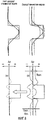
фиг.4 - развернутый график плотности из буровой скважины, на котором графически представлен сдвиг по высоте границы осадочного слоя;4 is a detailed graph of the density of the borehole, which graphically shows the shift in height of the border of the sedimentary layer;
фиг.5 - иллюстрация плотности вмещающей породы и плотности заполнения с использованием анализа геометрических коэффициентов;5 is an illustration of the density of the enclosing rock and the density of filling using the analysis of geometric coefficients;
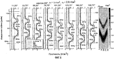
фиг.6 - информация диаграммы плотностного каротажа и изображение плотности, скорректированные за влияния эффективной глубины исследования и эффективного сдвига по высоте поверхности наклона границы слоя, связанных с эффективной глубиной исследования, согласно осуществлению изобретения;6 is information density density logs and density image, adjusted for the influence of the effective depth of the study and the effective shift along the height of the slope of the layer boundary associated with the effective depth of the study, according to an embodiment of the invention;
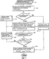
фиг.7 - блок-схема последовательности действий для получения скорректированной информации диаграммы плотностного каротажа и изображения плотности из фиг.6 согласно осуществлению настоящего изобретения;FIG. 7 is a flowchart for obtaining adjusted density log data and density images from FIG. 6 according to an embodiment of the present invention;
фиг.8 - иллюстрация определения зазора или постоянной плотности глинистой корки, используемого при осуществлении блок-схемы последовательности действий из фиг.7.Fig.8 is an illustration of determining the clearance or constant density of the clay cake used in the implementation of the flowchart of Fig.7.
Изобретение будет описано применительно к предпочтительным осуществлениям. Однако в той степени, в какой нижеследующее подробное описание является специфическим для конкретного осуществления или конкретного использования изобретения, оно предполагается только иллюстративным и не должно толковаться как ограничивающее объем изобретения. И наоборот, оно предполагается охватывающим все варианты, модификации и эквиваленты, которые могут быть включены в рамки сущности и объема изобретения, определенного прилагаемой формулой изобретения.The invention will be described with reference to preferred embodiments. However, to the extent that the following detailed description is specific to a particular embodiment or specific use of the invention, it is intended to be illustrative only and should not be construed as limiting the scope of the invention. Conversely, it is intended to encompass all variations, modifications, and equivalents that may be included within the spirit and scope of the invention as defined by the appended claims.
Подробное описание изобретенияDETAILED DESCRIPTION OF THE INVENTION
Краткое описание работы типичного двухдетекторного компенсированного прибора плотностного каротажа в процессе бурения и данных, собираемых им (то есть скважинных каротажных данных, в частности данных плотностного каротажа), дается для содействия пониманию концепций настоящего изобретения. Должно быть понятно, что настоящее изобретение можно использовать применительно к постобработке данных, получаемых приборами плотностного каротажа, а также другими приборами, а не типичным двухдетекторным компенсированным прибором плотностного каротажа в процессе бурения. Например, осуществления настоящего изобретения можно использовать применительно к конфигурациям спускаемых на кабеле приборов. Аналогично этому осуществления изобретения можно использовать применительно к приборам, обеспечивающим данные каротажа или изображения (то есть скважинные каротажные данные), содержащие геологические пласты, плотность, пористость, состав и т.д. или сочетания из них.A brief description of the operation of a typical two-detector compensated density logging tool during drilling and the data it collects (i.e., downhole logging data, in particular density logging data) is provided to facilitate understanding of the concepts of the present invention. It should be understood that the present invention can be applied to post-processing of data obtained by density logging tools, as well as other tools, rather than a typical two-detector compensated density logging tool during drilling. For example, embodiments of the present invention may be used with respect to cable lantern configurations. Similarly, this embodiment of the invention can be used with instruments providing log data or images (i.e., well log data) containing geological formations, density, porosity, composition, etc. or combinations of them.
На фиг.1 показана часть системы бурения, которую можно использовать для геологической разведки различных пластов и структур, которые существуют под земной поверхностью, и/или для достижения месторождений полезных ископаемых, таких как запасы углеводородов. Система бурения из фиг.1 включает в себя бурильную колонну 100, расположенную в буровой скважине 120. Хотя это не показано на чертеже, бурильная колонна 100 обычно содержит буровое долото на дистальном конце и буровую установку, включающую в себя буровую вышку, буровую лебедку и верхний привод, расположенные над бурильной колонной, для обеспечения вращательного (бурильного) и линейного (с введением и извлечением) перемещения бурильной колонны. Должно быть понятно, что хотя для упрощения чертежа показан промежуток (зазор) между стенками буровой скважины 120 и боковыми поверхностями бурильной колонны 100, в некоторых конфигурациях может не быть или по существу может не быть зазора между стенками буровой скважины 120 и боковыми поверхностями бурильной колонны 100. Кроме того, промежуток между стенками буровой скважины 120 и боковыми поверхностями бурильной колонны 100 может быть заполнен средой, такой как «буровой раствор» (промывочная жидкость или проппанты).Figure 1 shows a portion of a drilling system that can be used for geological exploration of various formations and structures that exist beneath the earth's surface, and / or to reach mineral deposits, such as hydrocarbon reserves. The drilling system of FIG. 1 includes a
Бурильная колонна 100 содержит прибор 110 плотностного каротажа, используемый для сбора информации о плотности применительно к пласту 140, показанному в виде, включающем в себя осадочные слои 141-145, разделенные соответствующими границами 146-149 слоев. Осадочные слои 141-145 могут содержать различные пластовые среды, например, осадочные слои 141, 143 и 145 содержат глинистый сланец, а осадочные слои 142 и 144 содержат песок. Прибор 100 плотностного каротажа из показанного осуществления представляет собой двухдетекторный прибор плотностного каротажа и поэтому включает в себя дальний от источника детектор 111, ближний к источнику детектор 112 и источник 113. Согласно осуществлениям источник 113 представляет собой источник гамма-излучения. В таком осуществлении дальний от источника детектор 111 и ближний к источнику детектор 112 представляют собой детекторы гамма-излучения, используемые для обнаружения гамма-излучения, как испускаемого от источника 113, так и рассеиваемого пластом 140. Распространение лучей от источника к детекторам представлено на фиг.1 пунктирными линиями 115 и 116 между источником 113 и каждым из дальнего от источника детектора 111 и ближнего к источнику детектора 112, соответственно.The
При работе бурильная колонна 100 и, следовательно, прибор 110 плотностного каротажа вращаются, так что множество азимутальных «видов» представляются для источника и датчиков прибора 110 плотностного каротажа. Например, поворот бурильной колонны 100 можно представить 16 шагами по 22,5° для получения видов на пласт 140, центрированных относительно 11,25°, 33,75°, 56,25°, 78,75°, 101,25°, 123,75°, 146,25°, 168,75°, 191,25°, 213,75°, 236,25°, 258,75°, 281,25°, 303,75°, 326,25° и 348,75°. Конечно, согласно осуществлениям изобретения в зависимости от апертуры, обеспечиваемой прибором 110 плотностного каротажа, можно использовать меньшее или большее количество азимутальных шагов. При этом каротажное оборудование 130, такое, которое может содержать процессор на базе системы управления, имеющей запоминающее устройство, сохраняющее набор инструкций, определяющих описанный в этой заявке процесс сбора, хранения и обработки информации от прибора 100 плотностного каротажа, можно использовать в сочетании с прибором 110 плотностного каротажа для выполнения измерений во множестве бинированных по азимуту секторов (например, в 16 бинированных секторах), чтобы получать диаграмму плотностного каротажа, обеспечивающую вид в пределах 360° вокруг буровой скважины 120 на конкретной глубине замера. Должно быть понятно, что при желании полный вид в пределах 360° можно не получать. Например, можно получать вид в пределах 180°, при этом вид в пределах остальных 180° можно оценивать или можно не оценивать как зеркальное отображение полученного вида.In operation, the
Значения плотности пласта можно оценивать как функцию скорости счета, например скорости (N) счета гамма-излучения, обеспечиваемой каждым из дальнего от источника детектора 111 и ближнего к источнику детектора. В приведенном выше примере скорости счета ближним к источнику и дальним от источника детекторами регистрируют и бинируют в 16 равномерно расположенных угловых секторов при вращении приборной колонны вокруг буровой скважины. Затем эти бинированные скорости счета можно обработать для вычисления компенсированных значений плотности в индивидуальных секторах.The values of the density of the formation can be estimated as a function of the count rate, for example, the count rate (N) of gamma radiation provided by each of the farthest from the source of the
При традиционном оценивании плотности предполагают, что пласт является бесконечно толстым (то есть однородным) в горизонтальном и вертикальном направлениях. В соответствии с этим способы, такие как широко используемый способ Δρ компенсации плотности, обеспечивают компенсацию за влияние смещения буровой скважины в каждом бине или азимутальном виде путем вычисления компенсированной плотности (ρкомп) как функции оценки плотности (ρLS) дальним от источника детектором, которая основана на скорости (NLS) счета дальнего от источника детектора, и функции разности между оценкой плотности дальним от источника детектором и оценкой плотности (ρSS) ближним к источнику детектором, которая основана на скорости (NSS) счета ближнего к источнику детектора, при этом эта разность обозначается как Δρ. Эти соотношения отражены ниже в следующих уравнениях:Conventional density estimation assumes that the formation is infinitely thick (i.e. uniform) in the horizontal and vertical directions. Accordingly, methods, such as the widely used density compensation method Δρ, compensate for the effect of the offset of the borehole in each bin or in the azimuthal form by calculating the compensated density (ρ comp ) as a function of estimating the density (ρ LS ) by a detector distant from the source based on speed (N LS) from the detector by the further source and the function of the difference between the density evaluation distant from the source and detector density estimate (ρ SS) proximal to the detector source which is based on ck grow (N SS) counting the SS detector, whereby this difference is designated as Δρ. These ratios are reflected below in the following equations:
Δρ=f(ρLS-ρSS),![]()
![]()
ρкомп=ρLS+Δρ.![]()
![]()
Компенсированные плотности, вычисленные для каждого бина, обычно кодируют цветом и наносят на 16-дорожечный чертеж для получения изображения плотности (например, «развернутого» вида плотности пласта из буровой скважины).The compensated densities calculated for each bin are usually color-coded and applied to a 16-track drawing to obtain a density image (for example, an “expanded” view of the density of a formation from a borehole).
Как можно понять, благодаря лучевому распространению трасс, представленных на фиг.1, упомянутый выше способ Δρ компенсации плотности может быть использован для получения относительно точной оценки плотности, которая является компенсированной за влияние смещения буровой скважины, в тех случаях, когда пласт является по существу однородным (то есть бесконечно толстым в горизонтальном и вертикальном направлениях) на глубине измерения. Однако каротажные диаграммы плотности, обеспечиваемые такими приборами плотностного каротажа, в последнее время находят многие применения, помимо геоуправления в реальном времени и выбора интервалов заканчивания скважин, в которых погрешности оценивания плотности, связанные с неоднородностью пласта, становятся значительными.As can be understood, due to the radial propagation of the paths shown in FIG. 1, the density compensation method Δρ mentioned above can be used to obtain a relatively accurate density estimate that is compensated for by the effect of the displacement of the borehole in cases where the formation is substantially uniform (i.e. infinitely thick in the horizontal and vertical directions) at the depth of measurement. However, the density logs provided by such density logging tools have recently found many applications, in addition to real-time geo-control and the choice of well completion intervals in which density estimation errors associated with reservoir heterogeneity become significant.
Изображения плотности из многих сложных коллекторов начали использовать для оценивания ската или наклона слоя (например, угла от горизонтали границы слоя 144 или границы слоя 145) и толщины (например, толщины осадочного слоя 142, определяемого границами 146 и 147 слоя). Однако в случаях крутых наклонных и горизонтальных скважин современная отраслевая практика построения изображений плотности с использованием данных о компенсированной плотности с ближнего к источнику и дальнего от источника детекторов и вычисления информации о наклоне может быть проблематичной. В частности, ко времени настоящего изобретения было обнаружено, что объем исследования (объем пласта, влияющего на измерение плотности) прибором плотностного каротажа, изменяющиеся углы между осью буровой скважины и плоскостями напластования и толщина слоя по-разному влияют на данные, собираемые на ближнем к источнику и дальнем от источника детекторах.Density images from many complex reservoirs began to be used to estimate the slope or inclination of the layer (for example, the angle from the horizontal of the
На фиг.2 показаны результаты моделирования методом Монте-Карло (МММК) для N частиц вычислений компенсированной плотности с использованием уравнений (1) и (2), приведенных выше, применительно к информации диаграммы плотностного каротажа, которую можно получить прибором плотностного каротажа, таким как прибор 110 плотностного каротажа, для пласта, имеющего осадочные слои из чередующихся сред, такие как показанные на фиг.1, расположенные в плоскостях, имеющих угол наклона 80° относительно скважины. Результаты моделирования на фиг.2 получены в отсутствии зазора между буровой скважиной и прибором, так что область плотности (ρ2) заполнения является бесконечно малой (например, глинистая корка отсутствует), и поэтому показана измеренная плотность вмещающей горной породы или плотность (ρ1) пласта (то есть Δρ должно быть равно нулю всюду). На фиг.2 в 8 графах слева направо представлены данные о плотности на азимутальных видах от 11,25° до 168,75° с приращениями по 22,5° на различных глубинах измерения. Линиями 201а-201h на соответствующем азимутальном виде представлена модельная плотность, при этом прямоугольные выступы соответствуют изменению плотности по причине чередования моделируемых осадочных слоев. Линиями 202а-202h на соответствующем азимутальном виде представлена плотность (ρSS) на ближнем к источнику детекторе (БД), определенная по полученной моделированием скорости (NSS) счета ближнего к источнику детектора. Линиями 203а-203h на соответствующем азимутальном виде представлена плотность (ρLS) на дальнем от источника детекторе (ДД), определенная по полученной моделированием скорости (NLS) счета дальнего от источника детектора. Линиями 204а-204h на соответствующем азимутальном виде представлена вычисленная компенсация (Δρ) плотности, определенная согласно уравнению (1). Линиями 205а-205h на соответствующем азимутальном виде представлена вычисленная компенсированная плотность (ρкомп), определенная согласно уравнению (2). Изображением, показанным справа на фиг.2, представлено изображение плотности (например развернутый вид плотности пласта из буровой скважины), полученное с использованием упомянутых выше данных о плотности.Figure 2 shows the results of Monte Carlo simulations (MMMK) for N compensated density computation particles using equations (1) and (2) above, with respect to density log information that can be obtained by a density log, such as
Вычисленная компенсированная плотность (ρкомп) имеет значительные погрешности на границах слоев. В частности, в показанном примере имеются значительные, смещенные вверх глубинные отклики для ρLS и (ρкомп) от азимута 11,25° до 101,25° и смещенные вниз глубинные отклики для ρLS и (ρкомп) от азимута 110, 25° до 168,75°. Поэтому изображения плотности, создаваемые на основании таких каротажных диаграмм ρLS и (ρкомп), будут некорректными. В частности, плотность пласта на конкретных измеренных глубинах будет некорректной, а геометрия пласта будет некорректно представленной.The calculated compensated density (ρ comp ) has significant errors at the boundaries of the layers. In particular, in the example shown, there are significant upwardly displaced depth responses for ρ LS and (ρ comp ) from azimuth 11.25 ° to 101.25 ° and downwardly displaced depth responses for ρ LS and (ρ comp ) from
Обнаружено, что ошибочное формирование Δρ, при котором вычисления Δρ приводят к неправильным знакам (то есть значение Δρ является отрицательным, когда оно должно быть положительным, и наоборот) на границах слоев, обусловлено по меньшей мере частично различными разрешением по вертикали и глубиной исследования между дальним от источника детектором и ближним к источнику детектором. Этим будет вноситься значительная погрешность плотности в тех случаях, когда процесс компенсации применяют, как показано в приведенном выше примере, к данным о плотности с двух детекторов из крутых наклонных или горизонтальных скважин.It was found that the erroneous formation of Δρ, in which the calculations of Δρ lead to incorrect signs (that is, the value of Δρ is negative when it should be positive, and vice versa) at the boundaries of the layers, is caused by at least partially different vertical resolution and depth of study between the far from the source to the detector and the detector closest to the source. This will introduce a significant density error in cases where the compensation process is applied, as shown in the above example, to the density data from two detectors from steep deviated or horizontal wells.
Осуществлениями настоящего изобретения обеспечивается точная информация о плотности независимо от геометрии пласта и буровой скважины. В соответствии с этим точная информация о плотности и, следовательно, точные изображения плотности могут быть получены применительно к крутым наклонным и горизонтальным скважинам и другим скважинам, в которых угол между нормалью плоскости пласта (например, осадочного слоя) и осью буровой скважины является отличным от нуля (то есть относительный наклон между буровой скважиной и пластом), а также к обычным вертикальным скважинам, имеющим крутой угол простирания на границах пласта. В дополнение к этому осуществлениями изобретения обеспечивается повышение разрешения применительно к скважинам, имеющим большой относительный наклон между буровой скважиной и пластом, а также скважинам, имеющим более крутой угол на границах пласта.By carrying out the present invention, accurate density information is provided regardless of the geometry of the formation and the borehole. Accordingly, accurate density information and, therefore, accurate density images can be obtained for steep deviated and horizontal wells and other wells in which the angle between the normal to the formation plane (e.g., the sedimentary layer) and the axis of the borehole is non-zero (i.e., the relative inclination between the borehole and the formation), as well as conventional vertical wells having a steep angle of strike at the boundaries of the formation. In addition to this, implementations of the invention provide an increase in resolution for wells having a large relative slope between the borehole and the formation, as well as wells having a steeper angle at the boundaries of the formation.
Обычно предполагается, что точка измерения для пары источник/детектор (например, для источника 113 и ближнего к источнику детектора 112 и источника 113 и дальнего от источника детектора 111) является срединной точкой между источником и детектором. Это предположение может обеспечивать приемлемые результаты в вертикальной скважине при горизонтальной геометрии слоя. Однако в крутых наклонных и горизонтальных скважинах границы слоев, обозначаемые точками перегиба каротажных диаграмм с ближнего к источнику и дальнего от источника детекторов, при пересечении прибором границы осадочного слоя появляются на опережающем месте по глубине, когда азимут прибора близок к нулю, и на месте дальше по глубине, когда азимут прибора близок к 180°. Это происходит потому, что прибором плотностного каротажа граница слоя выявляется не по глубине стенки ствола буровой скважины, а по глубине, которая определяется эффективным объемом исследования. Постобработку данных, получаемых прибором плотностного каротажа, таким как прибор 110 плотностного каротажа из фиг.1, выполняют согласно осуществлениям изобретения, используя анализ эффективного объема изобретения, чтобы точно определить плотность и геометрию пласта. Например, при выполнении постобработки данных прибора плотностного каротажа согласно осуществлениям изобретения глубинные границы (например, измеренную глубину) из информации о пласте, предоставляемой прибором плотностного каротажа, сдвигают в зависимости от азимута для коррекции пространственного положения признаков пласта, используя информацию об эффективном объеме исследования. Предпочтительно итерационно уточнять получаемые оценки плотности и угол наклона.It is generally assumed that the measurement point for the source / detector pair (for example, for
Объем исследования содержит область, просматриваемую или из которой ведутся подсчеты ближним к источнику и дальним от источника детекторами, и тем самым соответствует области под соответствующей одной из пунктирных линий 115 и 116. В соответствии с этим эффективный объем исследования двухдетекторным прибором плотностного каротажа, таким как прибор 110 плотностного каротажа, зависит от разнесения детекторов и свойств пласта и поэтому может быть оценен как функция указанного выше. Кроме того, эффективный объем исследования можно разложить в рамках известных концепций в членах радиальной глубины исследования, разрешения по вертикали и азимутальной апертуры (или Δφ), связанных с бининговыми измерениями прибора (например, азимутальной апертурой прибора 110). В вертикальной скважине радиальная глубина исследования влияет на измерение объемной плотности и разрешение по вертикали (эквивалентно осевому геометрическому коэффициенту), влияет на обнаружение границ слоев. Однако в крутых наклонных и горизонтальных скважинах радиальная глубина исследования (эквивалентно радиальному геометрическому коэффициенту) и разрешение по вертикали (эквивалентно осевому геометрическому коэффициенту) влияют на измерения плотности и обнаружение границ осадочных слоев. При большем угле наклона осадочного слоя существует более значительное влияние со стороны радиальной глубины исследования на осевое разрешение и оценку плотности.The scope of the study contains the area viewed or from which calculations are made near the source and far from the source by the detectors, and thus corresponds to the area under the corresponding one of the dashed
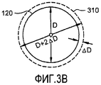
На фиг.3А-3С показаны концепции анализа эффективного объема исследования, используемого согласно осуществлениям изобретения. На фиг.3А-3С представлена буровая скважина 120, где плоскостью 340 обозначена плоскость границы осадочного слоя, такой как любая из границ 146-149 осадочных слоев, показанных на фиг.1, а плоскостью 350 обозначена плоскость, ортогональная к прибору 110 плотностного каротажа, такая, которая может соответствовать плоскости наблюдения прибора плотностного каротажа. Линией 310 обозначена радиальная глубина исследования прибора 110 плотностного каротажа. Хотя для упрощения чертежей на фиг.3А-3С представлена только одна линия радиальной глубины исследования, должно быть понятно, что каждому из дальнего от источника детектора 111 и ближнего к источнику детектора 112 соответствует особая радиальная глубина исследования. Линией 320 обозначена радиальная глубина исследования прибора 110 плотностного каротажа в плоскости границы осадочных слоев. И опять, хотя для упрощения чертежей на фиг.3А и 3С представлена только одна линия радиальной глубины исследования в плоскости границы осадочных слоев, должно быть понятно, что каждому из дальнего от источника детектора 111 и ближнего к источнику детектора 112 соответствует особая радиальная глубина исследования в плоскости границы слоев.On figa-3C shows the concept of analysis of the effective volume of research used according to the implementation of the invention. FIGS. 3A-3C show a borehole 120, where a
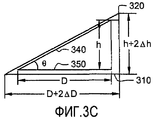
На фиг.3А-3С h представляет высоту поверхности наклона границы осадочного слоя над плоскостью наблюдения прибора плотностного каротажа на соответствующем азимутальном виде. Согласно этому h соответствует высоте синусоидальной линии на изображении плотности, имеющем конкретную границу осадочного слоя. D представляет диаметр буровой скважины, который является известным, и ΔD является эффективной глубиной исследования, которую можно оценивать на основании конфигурации прибора. В соответствии с этим, как можно видеть на фиг.3А-3С, Δh является эффективным сдвигом по высоте поверхности наклона границы осадочного слоя, связанным с эффективной глубиной исследования.On figa-3C h is the height of the surface of the slope of the boundary of the sedimentary layer above the observation plane of the density logging tool in the corresponding azimuthal form. According to this, h corresponds to the height of the sinusoidal line in the density image having a specific boundary of the sedimentary layer. D represents the diameter of the borehole, which is known, and ΔD is the effective depth of the study, which can be estimated based on the configuration of the device. Accordingly, as can be seen in FIGS. 3A-3C, Δh is the effective shear along the height of the slope of the sedimentary layer boundary associated with the effective depth of the study.
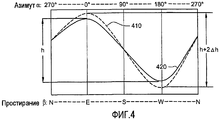
Упомянутый выше сдвиг по высоте границы осадочного слоя представлен графически на развернутом графике плотности, определенной из буровой скважины, показанном на фиг.4, где линией 410 представлено изображение плотности (например, ρSS, ρLS или ρкомп), «наблюдаемое» прибором плотностного каротажа (то есть на радиальной глубине исследования), тогда как линией 420 представлено изображение плотности (например, ρSS, ρLS или ρкомп), сдвинутое к стенке буровой скважины (то есть без сдвига радиальной глубины исследования, как это обычно бывает в предположении, что точка измерения для пары источник/детектор представляет собой срединную точку между источником и детектором). Сдвиг по высоте в крутых наклонных и горизонтальных скважинах является более очевидным относительно ρLS и ρкомп, поскольку ΔD больше для ρLS и ρкомп, чем для ρSS (что можно понять по эффективным областям исследования, обозначенным линиями 115 и 116 на фиг.1).The above-mentioned shift in height along the boundary of the sedimentary layer is presented graphically in a detailed density graph determined from the borehole shown in Fig. 4, where line 410 represents the density image (for example, ρ SS , ρ LS or ρ comp ), "observed" by the density device logging (that is, the radial depth of investigation) while
Было обнаружено, что такой сдвиг по высоте поверхности наклона границы осадочных слоев вносит значительную погрешность в изображение плотности, описанное выше относительно фиг.2. В частности, при сравнении диаграмм плотностного каротажа (линий 202а-202h, 203a-203h, 204a-204h и 205a-205h) с моделью плотности (линиями 201а-201h, которые представляют модель плотности пласта и поэтому соответствующим образом сдвинуты в зависимости от азимута при данном наклоне осадочного слоя) можно заметить значительные погрешности в связи с несоответствием глубины, обусловленным наклоном и эффективным объемом исследования. Следовательно, ΔD представляет собой параметр для определения положения по глубине, где каждым детектором обнаруживается граница осадочных слоев, и поэтому используется согласно осуществлениям изобретения для оценивания угла наклона границы осадочных слоев.It was found that such a shift along the height of the slope of the boundary of the sedimentary layers introduces a significant error in the density image described above with respect to FIG. In particular, when comparing density logs (
На основании связей, показанных на фиг.3А-3С, эффективный объем исследования (ЭОИ), используемый согласно осуществлениям изобретения, можно разложить, как показано ниже, в членах радиальной глубины исследования, разрешения по вертикали и азимутальной апертуры (Δφ):Based on the relationships shown in FIGS. 3A-3C, the effective research volume (EOI) used according to embodiments of the invention can be decomposed, as shown below, into terms of the radial depth of the study, vertical resolution, and azimuthal aperture (Δφ):
ЭОИ≡ΔD2·Δh·Δφ,![]()
![]()
где ΔD является функцией радиальной глубины исследования, Δφ определяется апертурой прибора плотностного каротажа; Δh является функцией радиальной глубины исследования и разрешения по вертикали. Таким эффективным объемом исследования унифицируется и определяется в пространстве разрешение прибора плотностного каротажа как функция радиальной глубины исследования, осевого разрешения и азимутальной апертуры. Благодаря изложенному выше исключается смешение влияния разрешения по вертикали прибора в вертикальной скважине и горизонтальном слое и влияния глубины исследования в крутых наклонных и горизонтальных скважинах.where ΔD is a function of the radial depth of the study, Δφ is determined by the aperture of the density logging tool; Δh is a function of the radial depth of investigation and vertical resolution. Such an effective volume of research unifies and determines in space the resolution of the density logging tool as a function of the radial depth of the study, axial resolution and azimuthal aperture. Thanks to the foregoing, the mixing of the effect of vertical resolution of the device in a vertical well and a horizontal layer and the influence of the depth of research in steep deviated and horizontal wells is eliminated.
Значение эффективного объема исследования можно оценить в зависимости от разнесения детекторов и свойств пласта. Анализ геометрических коэффициентов (то есть осевых и/или радиальных геометрических коэффициентов можно использовать при определении влияний свойств пласта на эффективную область исследования. Геометрические коэффициенты для двухдетекторного прибора плотностного каротажа, такого как прибор 110 плотностного каротажа, наряду с любым конкретным радиусом, начинающимся на передней поверхности прибора, и излучением с нее, можно определить в соответствии со следующим выражением:The value of the effective volume of research can be estimated depending on the diversity of the detectors and the properties of the reservoir. An analysis of geometric coefficients (that is, axial and / or radial geometric coefficients can be used to determine the effects of reservoir properties on the effective area of study. Geometric coefficients for a two-detector density logging tool, such as
G(r)=(ρ(r)-ρ1)/(ρ2-ρ1).![]()
![]()
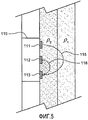
В приведенном выше уравнении ρ1 представляет собой плотность вмещающей горной породы (например, плотность пласта), и ρ2 представляет собой плотность заполнения (то есть плотность заполнения в зазоре или глинистой корки), показанные на фиг.5, которые по существу соответствуют ρSS и ρLS. Указанные выше геометрические коэффициенты используют при анализе на основе измеренной плотности для оценивания эффективной области исследования. В частности, было обнаружено, что в случае плотности вмещающей горной породы и плотности заполнения в пределах от 1,66 до 2,65 г/см3 (например, плотностей глинистой корки и подземного пласта, обычно связанных с разведкой на нефть и газ) радиальные глубины при G(r)=0,5 являются почти постоянными и поэтому по существу не зависят от конкретных, известных из опыта плотностей. То есть было определено, что чувствительность радиального геометрического коэффициента G(r) к контрасту плотности пласта является небольшой и поэтому радиальная глубина исследования пренебрежимо мало зависит от изменения плотности. В результате было установлено, что радиальная глубина при G(r)=0,5 эквивалентна отраслевой стандартной глубине исследования (например, 50% вклада в счет детектора вносится с этой глубины и 50% вклада в счет детектора вносится из участка вне этой глубины). В соответствии с этим согласно осуществлениям изобретения эффективную область исследования можно оценивать на основании указанных выше геометрических коэффициентов и информации о плотности (используя, например, исходные вычисления плотности (ρSS, ρLS и/или ρкопм) из каротажных диаграмм плотности).In the above equation, ρ 1 is the density of the host rock (e.g., the density of the formation), and ρ 2 is the fill density (i.e., the fill density in the gap or clay cake) shown in Fig. 5, which essentially correspond to ρ SS and ρ LS . The above geometric coefficients are used in the analysis based on the measured density to evaluate the effective area of study. In particular, it was found that in the case of host rock density and filling density in the range of 1.66 to 2.65 g / cm 3 (for example, clay cake and subterranean formation densities typically associated with oil and gas exploration) the depths at G (r) = 0.5 are almost constant and therefore essentially independent of specific densities known from experience. That is, it was determined that the sensitivity of the radial geometric coefficient G (r) to the contrast in the density of the formation is small and therefore the radial depth of the study is negligible depending on the change in density. As a result, it was found that the radial depth at G (r) = 0.5 is equivalent to the industry standard research depth (for example, 50% of the contribution to the detector is made from this depth and 50% of the contribution to the detector is made from a section outside this depth). Accordingly, according to embodiments of the invention, an effective research area can be estimated based on the above geometric coefficients and density information (using, for example, initial density calculations (ρ SS , ρ LS and / or ρ kpm ) from density logs).
Относительную оценку (θ) угла наклона границы осадочных слоев, показанную на фиг.3С, можно вычислить следующим образом:The relative estimate (θ) of the angle of inclination of the boundary of the sedimentary layers, shown in figs, can be calculated as follows:
![]()
![]()
![]()
![]()
Как рассматривалось выше, h является амплитудой синусоидальной линии (например, высотой поверхности наклона) из изображения плотности, D является диаметром буровой скважины, ΔD является эффективной глубиной исследования, которая представляет собой функцию радиальной глубины исследования, Δh является эффективным сдвигом по высоте (например, глубиной в глубине замера) границы поверхности наклона. В предположении небольшой погрешности ΔD и Δh погрешность (Δθ) оценки можно выразить в виде:As discussed above, h is the amplitude of the sinusoidal line (for example, the height of the tilt surface) from the density image, D is the diameter of the borehole, ΔD is the effective depth of the study, which is a function of the radial depth of the study, Δh is the effective shift in height (for example, depth in the depth of measurement) of the boundary of the slope surface. Assuming a small error ΔD and Δh, the error (Δθ) of the estimate can be expressed as:
![]()
![]()
![]()
![]()
На основании изложенного выше расстояние между фактическим местоположением границы осадочных слоев и границей осадочных слоев, получаемое по диаграмме плотностного каротажа, или Δh, представляет собой эффективный сдвиг по высоте (например, глубину в замере глубины) границы поверхности наклона, показанный на фиг.3А-3С. Пересечение идеализированного эффективного объема исследования, указанное в уравнении (3), при заданном ΔD с границей слоев дает геометрическое соотношение для определения Δh для каждого детектора (например, ΔhSS и ΔhLS). При развертывании стенки буровой скважины в плоскую поверхность, показанную на фиг.4, значение Δh для каждого детектора можно оценить в зависимости от азимутального поворота при заданном угле наклона с помощью:Based on the foregoing, the distance between the actual location of the boundary of the sedimentary layers and the boundary of the sedimentary layers, obtained from the density log, or Δh, is the effective height shift (for example, depth in depth measurement) of the inclined surface boundary shown in Figs. 3A-3C . The intersection of the idealized effective research volume specified in equation (3), for a given ΔD with the boundary of the layers gives a geometric relationship for determining Δh for each detector (for example, Δh SS and Δh LS ). When deploying the wall of the borehole in a flat surface, shown in figure 4, the value of Δh for each detector can be estimated depending on the azimuthal rotation at a given angle of inclination using:
Δh=ΔDcos(α+β)tan(θ).![]()
![]()
В приведенном выше уравнении α является азимутом передней стороны прибора плотностного каротажа (то есть направлением обзора прибора плотностного каротажа), β является простиранием (то есть азимутом пересечения наклонного слоя с горизонтальной плоскостью) наклонного слоя (или искривленной буровой скважины), и θ является относительным наклоном между буровой скважиной и слоем пласта. Из изложенного выше можно видеть, что осуществления настоящего изобретения можно использовать для графического построения границ осадочных слоев в зависимости от азимута.In the above equation, α is the azimuth of the front side of the density logging tool (i.e., the direction of view of the density logging tool), β is the strike (i.e. the azimuth of the intersection of the inclined layer with the horizontal plane) of the inclined layer (or curved borehole), and θ is the relative inclination between the borehole and the formation layer. From the above it can be seen that the implementation of the present invention can be used to graphically plot the boundaries of the sedimentary layers depending on the azimuth.
На фиг.6 показано, в каких местах ρLS, ρSS и ρкомп из примера, показанного на фиг.2, были сдвинуты после использования приведенных выше уравнений для решения относительно Δh. В частности, на фигуре показаны сдвиги ρLS на ΔhLS и ρSS на ΔhSS, так что ρкомп сдвигается на соответствующую величину Δh. На фиг.6, как и на фиг.2, на 8 диаграммах, показанных слева направо, представлены данные о плотности на азимутальных видах 11,25°-168,75° с приращением по 22,5° на различных измеренных глубинах. Линиями 201a-201h представлена модельная плотность на соответствующем азимутальном виде, при этом прямоугольные выступы соответствуют изменению плотности в результате чередования моделируемых осадочных слоев. Линиями 602a-602h представлена плотность (ρSS) на ближнем к источнику детекторе (БД), сдвинутая на ΔhSS. Линиями 603a-603h представлена плотность (ρLS) на дальнем от источника детекторе (ДД), сдвинутая на ΔhLS.Figure 6 shows in which places ρ LS , ρ SS and ρ comp from the example shown in figure 2, were shifted after using the above equations to solve for Δh. In particular, the figure shows the shift in ρ LS Δh LS and ρ SS on Δh SS, so that ρ Comp shifted by an appropriate amount Δh. In Fig. 6, as in Fig. 2, 8 diagrams shown from left to right show density data in azimuthal views of 11.25 ° -168.75 ° in increments of 22.5 ° at various measured depths.
Из сравнения линий 604a-604h из фиг.6 (после коррекции за влияние анализа эффективного объема исследования) с линиями 204a-204h из фиг.2 (до коррекции) видно, что величина Δρ существенно снизилась и стала состоятельной на протяжении всех азимутальных секторов. Как можно понять, линии 602a-602h и 603a-603h более близко соответствуют прямоугольным выступам модельной плотности на линиях 201а и 201h, чем это делают линии 202a-202h и 203a-203h из фиг.2. Аналогичным образом компенсированная плотность ρкомп на линиях 605a-605h, вычисленная на основании плотности (ρLS) на дальнем от источника детекторе и плотности (ρSS) на ближнем от источника детекторе, сдвинутых на соответствующие сдвиги (ΔhLS и ΔhSS) по высоте, более близко соответствует прямоугольным выступам модельной плотности на линиях 201a-201h, чем это делают линии 205a-205h из фиг.2. В соответствии с этим точка перегиба на каротажных диаграммах дальнего от источника детектора и ближнего к источнику детектора, а также компенсированная плотность, вычисляемая по ней, совмещается с фактическими границами осадочных слоев, вследствие чего это приводит к более точной информации о пласте независимо от геометрии пласта и буровой скважины. Кроме того, результирующее синусоидальное изображение компенсированной плотности имеет меньшую высоту (h) после применения коррекции за влияние ΔD, что приводит к более точной оценке наклона.From a comparison of
Имея описанные выше концепции настоящего изобретения, на фиг.7 показана блок-схема последовательности действий, предоставляющая дополнительные подробности способа согласно предпочтительному осуществлению настоящего изобретения. Хотя для упрощения представленных концепций в рассмотренных выше примерах предполагалось отсутствие зазора или глинистой корки, в осуществлении из фиг.7 обеспечивается компенсация при наличии и отсутствии зазора или глинистой корки.Having the concepts of the present invention described above, FIG. 7 is a flowchart providing further details of a method according to a preferred embodiment of the present invention. Although to simplify the concepts presented in the examples discussed above, the absence of a gap or clay cake was assumed, in the embodiment of FIG. 7, compensation is provided for the presence and absence of a gap or clay cake.
В блоке 701 (фиг.7) прибор 110 плотностного каротажа и каротажное оборудование 130 используют для сбора азимутальных каротажных данных об объемной плотности. Эти каротажные данные можно использовать при построении исходного (не корректированного в соответствии с Δh) изображения плотности, например, в течение работы каротажного оборудования 130 или другой, основанной на процессоре системы. В блоке 702 угол наклона осадочного слоя и границы осадочных слоев оценивают, используя исходные данные плотностного каротажа (например, данные дальнего от источника детектора (ДД) и ближнего к источнику детектора (БД)), описанные выше. В дополнение к этому в показанном осуществлении также вычисляют Δρ на основании исходных данных плотностного каротажа, применяя уравнение (1), чтобы использовать при ослаблении влияний зазора или глинистой корки.In block 701 (FIG. 7), the
В блоке 703 определяют, указывает ли вычисленное значение Δρ на наличие зазора или глинистой корки. Например, в случае, если Δρ является по существу постоянным положительным или отрицательным значением на всем протяжении участка пласта, который не пересекает границу осадочного слоя (см. фиг.8), то, вероятно, что это значение Δρ связано с зазором или глинистой коркой. Если определяют, что существует зазор или глинистая корка, то в блоке 707 постоянное значение Δρ, связанное с Δρс, вычитают из данных ближнего к источнику детектора и дальнего от источника детектора (например, ρSS и ρLS), чтобы исключить влияния зазора или глинистой корки, и в блоке 704 продолжают обработку. Если определяют, что зазора или глинистой корки нет, то обработку также продолжают в блоке 704 показанного осуществления.In
В блоке 704 анализ эффективного объема исследования (ЭОИ) согласно настоящему изобретению с использованием ΔD и Δh, поясненных выше, обеспечивает коррекцию данных ближнего к источнику детектора и дальнего от источника детектора в зависимости от относительного наклона, азимута и угла простирания. В блоке 704 иллюстрируемым осуществлением изобретения обеспечивается повышение разрешения по вертикали путем изменения знака (+/-) Δρ и добавления этого значения к ρLS. Как можно видеть по линиям 201а и 203а и линиям 201h и 203h, добавление Δρ, имеющего измененный знак, к ρLS обеспечивает сдвиг замера глубины на ρLS.In
В блоке 705 угол наклона осадочного слоя повторно оценивают на основании скорректированных данных ближнего к источнику детектора и дальнего от источника детектора. Хотя в данном случае повторное оценивание угла наклона на основании данных ближнего к источнику детектора и дальнего от источника детектора показано как отдельный этап, должно быть понятно, что такое повторное оценивание может быть выполнено как обработка, показанная в блоке 704.At
В блоке 706 определяют, должны ли применяться к каротажным плотностным данным дальнейшие итерации анализа эффективного объема исследования и коррекции. Например, когда данные корректируют, итерационное улучшение результатов становится меньше, так что дальнейшие итерации не обеспечивают получения значительно улучшенных результатов. В соответствии с этим в осуществлениях изобретения, в которых используют итерационный процесс, выполняют действие, чтобы определить, требуются ли дальнейшие итерации анализа эффективного объема исследования. В иллюстрируемом осуществлении вычисляют погрешность оценки (Δθ) наклона, показанную в уравнении (6), и сравнивают эту погрешность оценки наклона с разностью оцененного угла наклона из текущей итерации и оцененного угла наклона из предшествующей итерации, чтобы определить, должны ли проводиться дальнейшие итерации. Если погрешность оценки наклона меньше или равна разности оцененного угла наклона из текущей итерации и оцененного угла наклона из предшествующей итерации или заданного порогового значения, а объемная плотность для этих итераций пересекает границу осадочного пласта, обработку продолжают согласно блоку 709 для выполнения дальнейшей итерации.At
В блоке 709 скорректированные данные ближнего к источнику детектора (БД) и дальнего от источника детектора (ДД) используют для получения улучшенного изображения плотности и новой оценки угла наклона. После этого обработку возвращают к блоку 704 для анализа эффективного объема исследования (ЭОИ), описанного выше.In
Если анализ погрешности оценки наклона, выполненный в блоке 706, не показывает, что дальнейшие итерации требуются, обработку продолжают в блоке 708, при этом конечные данные ближнего к источнику детектора и дальнего от источника детектора используют для получения конечного улучшенного изображения плотности. В случаях, когда в блоке 703 определяют наличие зазора или глинистой корки, компенсированную плотность (ρкомп) вычисляют в блоке 708 иллюстрируемого осуществления путем добавления Δρс, которое было вычтено в блоке 707 для исключения влияний зазора и глинистой корки, к конечному скорректированному ρLS. В соответствии с этим постобработка данных прибора плотностного каротажа, предусмотренная в осуществлениях изобретения, может быть использована для получения точной плотности и повышения разрешения применительно к приборам плотностного каротажа, в которых датчики приборов расположены вплотную к стенке буровой скважины (то есть зазор отсутствует). Аналогичным образом приведенные выше способы постобработки, приспособленные для ввода параметра зазора (например, поправочной постоянной Δρс плотности), можно использовать для получения точной плотности и повышения разрешения применительно к приборам плотностного каротажа, в которых датчики приборов расположены на расстоянии от стенки буровой скважины (то есть зазор имеется).If the analysis of the slope estimation error performed in
Как показано выше, основанная на эффективном объеме исследования, зависящая от азимута и угла наклона коррекция ΔD и Δh, предусмотренная согласно осуществлениям изобретения, приводит к получению улучшенных компенсированных диаграмм плотностного каротажа и изображений плотности при более точных наклоне и границах слоя. Хотя в этой заявке изобретение описано при обращении к осуществлениям с использованием двухдетекторных приборов плотностного гамма-каротажа, концепции изобретения можно применять к другим конфигурациям приборов плотностного каротажа, таким как двухдетекторные, спускаемые на кабеле приборы и приборы нейтронного каротажа в процессе бурения. Аналогично этому концепции настоящего изобретения не ограничены конфигурациями двухдетекторных приборов плотностного каротажа. Например, коррекцию ΔD и Δh, показанную в этом изобретении, можно применять к изображениям, получаемым одним детектором, для построения улучшенного компенсированного изображения при намного более точной оценке границ слоев и угла наклона. Поэтому должно быть понятно, что концепции настоящего изобретения можно использовать применительно к любым приборам и измерениям, в которых встречаются проблемы, связанные с глубиной и точкой измерения, обусловленные эффективным объемом исследования.As shown above, based on the effective study volume, azimuth and inclination angle-dependent correction ΔD and Δh provided by the embodiments of the invention results in improved compensated density logs and density images with more accurate slope and layer boundaries. Although the invention is described in this application when referring to implementations using two-detector density gamma-ray logging tools, the concepts of the invention can be applied to other configurations of density logging instruments, such as two-detector, cabled and neutron logging tools during drilling. Similarly, the concepts of the present invention are not limited to the configurations of two-detector density logging tools. For example, the correction ΔD and Δh shown in this invention can be applied to images obtained by a single detector to construct an improved compensated image with a much more accurate estimate of the layer boundaries and the angle of inclination. Therefore, it should be clear that the concepts of the present invention can be applied to any instruments and measurements that encounter problems associated with the depth and measurement point due to the effective scope of the study.
Хотя настоящее изобретение и его преимущества были описаны подробно, должно быть понятно, что различные изменения, замены и варианты могут быть сделаны в этой заявке без отступления от сущности и объема изобретения, определяемого прилагаемой формулой изобретения. Кроме того, объем настоящего изобретения не должен ограничиваться конкретными осуществлениями процессов, устройств, технологий изготовления, составами материалов, средствами, способами и этапами, рассмотренными в описании. Специалист в данной области техники может без труда понять на основании раскрытия настоящего изобретения, что процессы, устройства, технологии изготовления, составы материалов, средства, способы или этапы, существующие в настоящее время или которые будут разработаны позднее, выполняющие по существу ту же самую функцию или позволяющие получать по существу такой же результат, как и соответствующие осуществления, описанные в этой заявке, можно использовать в соответствии с настоящим изобретением. В соответствии с этим предполагается, что такие процессы, устройства, технологии изготовления, составы материалов, средства, способы или этапы включены в объем прилагаемой формулы изобретения.Although the present invention and its advantages have been described in detail, it should be understood that various changes, substitutions, and variations can be made in this application without departing from the spirit and scope of the invention as defined by the appended claims. In addition, the scope of the present invention should not be limited to specific implementations of the processes, devices, manufacturing techniques, compositions of materials, means, methods and steps described in the description. One of ordinary skill in the art can readily understand, based on the disclosure of the present invention, that processes, devices, manufacturing techniques, compositions of materials, means, methods or steps that currently exist or that will be developed later that perform essentially the same function or allowing to obtain essentially the same result as the corresponding implementation described in this application can be used in accordance with the present invention. In accordance with this, it is assumed that such processes, devices, manufacturing techniques, compositions of materials, means, methods or steps are included in the scope of the attached claims.
Claims (25)
оценивают глубину границы пласта на основании скважинных каротажных данных, при этом указанные скважинные каротажные данные обеспечивают данные о параметрах пласта для множества азимутальных углов, причем указанную глубину границы пласта оценивают для каждого из указанных азимутальных углов;
анализируют информацию об эффективном объеме исследования, чтобы определить эффективную глубину (ΔD) исследования и эффективный сдвиг (Δh) по высоте поверхности границы пласта, связанные с указанной глубиной границы пласта; и
уточняют указанную оценку глубины границы пласта, используя по меньшей мере одно из указанной эффективной глубины (ΔD) исследования и указанного эффективного сдвига (Δh) по высоте.1. The method of estimating the depth of the boundary of the reservoir, which consists in the fact that:
estimating the depth of the reservoir boundary based on downhole logging data, wherein said downhole logging data provides data on formation parameters for a plurality of azimuthal angles, wherein said reservoir depth is estimated for each of said azimuthal angles;
analyze information about the effective volume of the study to determine the effective depth (ΔD) of the study and the effective shift (Δh) along the height of the surface of the reservoir boundary associated with the specified depth of the reservoir boundary; and
refine the specified estimate of the depth of the reservoir boundary using at least one of the indicated effective depth (ΔD) of the study and the specified effective shift (Δh) in height.
определение значения эффективного объема исследования как функции геометрических коэффициентов и указанных скважинных каротажных данных.3. The method according to claim 1, in which the specified analysis of information about the effective scope of the study contains:
determination of the value of the effective volume of the study as a function of geometric coefficients and the indicated borehole logging data.
разложение указанной информации об эффективном объеме исследования в членах радиальной глубины исследования, разрешения по вертикали и азимутальной апертуры.4. The method according to claim 1, in which the specified analysis of information about the effective scope of the study contains:
decomposition of the indicated information on the effective volume of the study in terms of the radial depth of the study, vertical resolution and azimuthal aperture.
повторное оценивание указанной глубины границы пласта на основании скорректированных скважинных каротажных данных, при этом указанные скорректированные скважинные каротажные данные содержат указанные скважинные каротажные данные, имеющие указанное по меньшей мере одно из указанной эффективной глубины (ΔD) исследования и указанного эффективного сдвига (Δh) по высоте, применяемое для этого.5. The method according to claim 1, in which the specified refinement of the specified assessment of the depth of the boundary of the reservoir contains:
re-evaluating the indicated depth of the reservoir boundary based on the corrected well log data, wherein said corrected well log data contains said well log data having at least one of said effective exploration depth (ΔD) and said effective shift (Δh) in height, used for this.
оценивание угла наклона границы пласта на основании указанных скважинных каротажных данных; и
уточнение указанной оценки угла наклона границы пласта при использовании по меньшей мере одного из указанной эффективной глубины (ΔD) исследования и указанного эффективного сдвига (Δh) по высоте.6. The method according to claim 1, additionally containing:
Estimation of the inclination angle of the reservoir boundary based on the specified well log data; and
refinement of the indicated estimation of the inclination angle of the formation boundary using at least one of the indicated effective depth (ΔD) of the study and the indicated effective shift (Δh) in height.
повторное оценивание указанного угла наклона границы пласта на основании скорректированных скважинных каротажных данных, при этом указанные скорректированные скважинные каротажные данные содержат указанные скважинные каротажные данные, имеющие указанное по меньшей мере одно из указанной эффективной глубины (ΔD) исследования и указанного эффективного сдвига (Δh) по высоте, применяемое для этого.7. The method according to claim 6, in which the specified refinement of the specified evaluation of the angle of inclination of the boundary of the reservoir contains:
reevaluating the indicated inclination angle of the formation boundary based on the corrected downhole logging data, wherein said corrected downhole logging data contains said downhole logging data having at least one of said effective exploration depth (ΔD) and said effective vertical shift (Δh) in height used for this.
вычитание поправочной постоянной (Δρc) плотности из указанных скважинных каротажных данных до указанного анализа указанной информации об эффективном объеме исследования.8. The method according to claim 1, additionally containing:
subtracting the correction constant (Δρ c ) density from the indicated well log data before the specified analysis of the indicated information about the effective volume of the study.
добавление указанной поправочной постоянной (Δρc) плотности к скорректированным скважинным каротажным данным до получения конечной оценки глубины границы пласта на основании указанной уточненной оценки глубины границы пласта.9. The method of claim 8, further comprising:
adding the indicated correction constant (Δρ c ) density to the corrected borehole logging data to obtain a final estimate of the depth of the reservoir boundary based on the specified updated assessment of the depth of the reservoir boundary.
оценивают угол наклона границы пласта на основании скважинных каротажных данных, при этом указанные скважинные каротажные данные обеспечивают данные о параметрах пласта для множества азимутальных углов;
анализируют информацию об эффективном объеме исследования, чтобы определить эффективную глубину (ΔD) исследования и эффективный сдвиг (Δh) по высоте поверхности наклона границы пласта, связанные с указанным углом наклона границы пласта; и
уточняют указанную оценку угла наклона границы пласта, используя по меньшей мере одно из указанной эффективной глубины (ΔD) исследования и указанного эффективного сдвига (Δh) по высоте.10. A method for assessing the angle of inclination of the boundary of the reservoir, which consists in the fact that:
estimating an inclination angle of the formation boundary based on the well log data, wherein said well log data provides formation parameter data for a plurality of azimuthal angles;
analyze information about the effective volume of the study to determine the effective depth (ΔD) of the study and the effective shift (Δh) along the height of the surface of the inclination of the reservoir boundary, associated with the specified angle of inclination of the reservoir boundary; and
specify the specified assessment of the angle of inclination of the reservoir boundary, using at least one of the specified effective depth (ΔD) of the study and the specified effective shift (Δh) in height.
определение значения эффективного объема исследования как функции геометрических коэффициентов и указанных скважинных каротажных данных.12. The method according to claim 10, in which the specified analysis of information about the effective volume of the study contains:
determination of the value of the effective volume of the study as a function of geometric coefficients and the indicated borehole logging data.
разложение указанной информации об эффективном объеме исследования в членах радиальной глубины исследования, разрешения по вертикали и азимутальной апертуры.13. The method according to claim 10, in which the specified analysis of information about the effective volume of the study contains:
decomposition of the indicated information on the effective volume of the study in terms of the radial depth of the study, vertical resolution and azimuthal aperture.
повторное оценивание указанного угла наклона границы пласта на основании скорректированных скважинных каротажных данных, при этом указанные скорректированные скважинные каротажные данные содержат указанные скважинные каротажные данные, имеющие указанное по меньшей мере одно из указанной эффективной глубины (ΔD) исследования и указанного эффективного сдвига (Δh) по высоте, применяемое для этого.14. The method according to claim 10, in which the specified refinement of the specified estimates of the angle of inclination of the boundary of the reservoir contains:
reevaluating the indicated inclination angle of the formation boundary based on the corrected downhole logging data, wherein said corrected downhole logging data contains said downhole logging data having at least one of said effective exploration depth (ΔD) and said effective vertical shift (Δh) in height used for this.
оценивание глубины границы пласта для каждого из указанных азимутальных углов на основании указанных скважинных каротажных данных; и
уточнение указанной оценки глубины границы пласта при использовании по меньшей мере одного из указанной эффективной глубины (ΔD) исследования и указанного эффективного сдвига (Δh) по высоте.15. The method according to claim 10, further comprising:
estimating the depth of the reservoir boundary for each of the indicated azimuthal angles based on the specified well log data; and
refinement of the indicated estimate of the depth of the reservoir boundary using at least one of the indicated effective depth (ΔD) of the study and the indicated effective shift (Δh) in height.
повторное оценивание указанной глубины границы пласта на основании скорректированных скважинных каротажных данных, при этом указанные скорректированные скважинные каротажные данные содержат указанные скважинные каротажные данные, имеющие указанное по меньшей мере одно из указанной эффективной глубины (ΔD) исследования и указанного эффективного сдвига (Δh) по высоте, применяемое для этого.16. The method according to clause 15, in which the specified refinement of the specified estimates of the depth of the boundary of the reservoir contains:
re-evaluating the indicated depth of the reservoir boundary based on the corrected well log data, wherein said corrected well log data contains said well log data having at least one of said effective exploration depth (ΔD) and said effective shift (Δh) in height, used for this.
вычитание поправочной постоянной (Δρc) плотности из указанных скважинных каротажных данных до указанного анализа указанной информации об эффективном объеме исследования.17. The method of claim 10, further comprising:
subtracting the correction constant (Δρ c ) density from the indicated well log data before the specified analysis of the indicated information about the effective volume of the study.
добавление указанной поправочной постоянной (Δρc) плотности к скорректированным скважинным каротажным данным до получения конечной оценки угла наклона границы пласта на основании указанной уточненной оценки угла наклона границы пласта.18. The method according to 17, further comprising:
adding the indicated correction constant (Δρ c ) density to the corrected borehole logging data until a final estimate of the formation boundary angle is obtained based on the specified updated estimate of the formation boundary angle.
программу для определения эффективного сдвига (Δh) по высоте поверхности наклона границы пласта, представленного скважинными каротажными данными, при этом указанный эффективный сдвиг (Δh) по высоте определяется с использованием по меньшей мере части указанных скважинных каротажных данных; и
программу для коррекции по меньшей мере одного из угла наклона границы пласта и глубины границы пласта с использованием указанного эффективного сдвига (Δh) по высоте, в котором указанный угол наклона границы пласта и указанная глубина границы пласта определяются на основании указанных скважинных каротажных данных.19. A computer-readable medium comprising a computer-executable program, the computer executing a method for processing downhole logging data, wherein said program comprises:
a program for determining the effective shift (Δh) along the height of the surface of the slope of the reservoir boundary represented by borehole logging data, wherein said effective shift (Δh) along the height is determined using at least a portion of said borehole logging data; and
a program for correcting at least one of an angle of inclination of a formation boundary and a depth of a boundary of a formation using a specified effective shift (Δh) in height at which a specified angle of inclination of a boundary of a formation and a specified depth of a boundary of a formation are determined based on said well log data.
программу для итерационного уточнения указанного по меньшей мере одного из указанного угла наклона границы пласта и указанной глубины границы пласта.21. The computer-readable medium of claim 19, wherein said program for correcting said at least one of said inclination angle of a formation boundary and said depth of a formation boundary comprises:
a program for iterative refinement of said at least one of a specified inclination angle of a formation boundary and a specified depth of a formation boundary.
программу для вычисления указанного эффективного сдвига (Δh) по высоте с использованием информации об эффективном объеме исследования.22. The computer-readable medium of claim 19, wherein said program for determining an effective height shift (Δh) comprises:
a program for calculating the indicated effective shift (Δh) in height using information about the effective volume of the study.
Applications Claiming Priority (3)
| Application Number | Priority Date | Filing Date | Title |
|---|---|---|---|
| US559107P | 2007-12-06 | 2007-12-06 | |
| US61/005,591 | 2007-12-06 | ||
| PCT/US2008/079571 WO2009073277A1 (en) | 2007-12-06 | 2008-10-10 | Volume of investigation based image processing |
Publications (2)
| Publication Number | Publication Date |
|---|---|
| RU2010127859A RU2010127859A (en) | 2012-01-20 |
| RU2483333C2 true RU2483333C2 (en) | 2013-05-27 |
Family
ID=40718086
Family Applications (1)
| Application Number | Title | Priority Date | Filing Date |
|---|---|---|---|
| RU2010127859/28A RU2483333C2 (en) | 2007-12-06 | 2008-10-10 | Volume of investigation based image processing |
Country Status (8)
| Country | Link |
|---|---|
| US (1) | US8527204B2 (en) |
| EP (1) | EP2223163A4 (en) |
| AU (1) | AU2008331710B2 (en) |
| BR (1) | BRPI0820955B1 (en) |
| CA (1) | CA2701815A1 (en) |
| MY (1) | MY151715A (en) |
| RU (1) | RU2483333C2 (en) |
| WO (1) | WO2009073277A1 (en) |
Families Citing this family (10)
| Publication number | Priority date | Publication date | Assignee | Title |
|---|---|---|---|---|
| US8228758B2 (en) * | 2009-01-21 | 2012-07-24 | Schlumberger Technology Corporation | Image generation of a wellbore |
| US9043153B2 (en) * | 2011-03-15 | 2015-05-26 | Schlumberger Technology Corporation | Maximum depth of investigation of measurements in a formation |
| CN105164729A (en) * | 2013-03-29 | 2015-12-16 | 普拉德研究及开发股份有限公司 | Image symmetry for dip determination |
| US20150120199A1 (en) * | 2013-10-31 | 2015-04-30 | Matthew S. Casey | Multiple Domain Processing For Combining Reservoir Models and Seismic Data |
| WO2015178945A1 (en) * | 2014-05-20 | 2015-11-26 | Halliburton Energy Services, Inc. | Improving well survey performance |
| US10192007B2 (en) | 2014-12-05 | 2019-01-29 | General Electric Company | System and method for estimating material density |
| US20180059276A1 (en) * | 2016-08-25 | 2018-03-01 | Waveseis LLC | System and method for focusing seismic images |
| CN110320572B (en) * | 2018-03-29 | 2021-04-23 | 中国石油化工股份有限公司 | Method and system for identifying sedimentary facies |
| CN110320573B (en) * | 2018-03-29 | 2021-05-25 | 中国石油化工股份有限公司 | Logging parameter construction method and system reflecting reservoir productivity |
| CN109633781B (en) * | 2018-08-16 | 2021-03-02 | 清能艾科(深圳)能源技术有限公司 | Geological property acquisition method and device, electronic equipment and storage medium |
Citations (4)
| Publication number | Priority date | Publication date | Assignee | Title |
|---|---|---|---|---|
| US5091644A (en) * | 1991-01-15 | 1992-02-25 | Teleco Oilfield Services Inc. | Method for analyzing formation data from a formation evaluation MWD logging tool |
| GB2280955A (en) * | 1993-08-12 | 1995-02-15 | Schlumberger Ltd | Correcting formation density measurements for non-source gamma radiation |
| EP0864884A2 (en) * | 1997-03-06 | 1998-09-16 | Schlumberger Limited | Method for determining formation density and formation photo-electric factor with a multi-detector-gamma-ray tool |
| RU2304292C2 (en) * | 2002-03-04 | 2007-08-10 | Бейкер Хьюз Инкорпорейтед | Method for determining bed position using results of multi-component induction logging in a horizontal well |
Family Cites Families (10)
| Publication number | Priority date | Publication date | Assignee | Title |
|---|---|---|---|---|
| US2712081A (en) * | 1955-06-28 | Method for neutron well logging x | ||
| US2957990A (en) * | 1956-01-03 | 1960-10-25 | Pan American Petroleum Corp | Well formation density logging |
| US6237404B1 (en) * | 1998-02-27 | 2001-05-29 | Schlumberger Technology Corporation | Apparatus and method for determining a drilling mode to optimize formation evaluation measurements |
| US6307199B1 (en) * | 1999-05-12 | 2001-10-23 | Schlumberger Technology Corporation | Compensation of errors in logging-while-drilling density measurements |
| US7114565B2 (en) * | 2002-07-30 | 2006-10-03 | Baker Hughes Incorporated | Measurement-while-drilling assembly using real-time toolface oriented measurements |
| US6795774B2 (en) * | 2002-10-30 | 2004-09-21 | Halliburton Energy Services, Inc. | Method for asymptotic dipping correction |
| US20060131016A1 (en) * | 2004-06-12 | 2006-06-22 | Ivan Snoga | Apparatus and method for determining the dip of an underground formation in a cased or uncased borehole |
| US7647182B2 (en) * | 2004-07-15 | 2010-01-12 | Baker Hughes Incorporated | Apparent dip angle calculation and image compression based on region of interest |
| US7657375B2 (en) * | 2006-04-26 | 2010-02-02 | Baker Hughes Incorporated | Method and apparatus for correcting underestimation of formation anisotropy ratio |
| CN101479732A (en) * | 2006-05-10 | 2009-07-08 | 贝克休斯公司 | Use of multi-component measurements in delineating geology of deep-water sediments |
-
2008
- 2008-10-10 EP EP08857750.7A patent/EP2223163A4/en not_active Withdrawn
- 2008-10-10 RU RU2010127859/28A patent/RU2483333C2/en active
- 2008-10-10 US US12/678,040 patent/US8527204B2/en active Active
- 2008-10-10 BR BRPI0820955-3A patent/BRPI0820955B1/en not_active IP Right Cessation
- 2008-10-10 AU AU2008331710A patent/AU2008331710B2/en not_active Ceased
- 2008-10-10 CA CA2701815A patent/CA2701815A1/en not_active Abandoned
- 2008-10-10 WO PCT/US2008/079571 patent/WO2009073277A1/en active Application Filing
- 2008-12-01 MY MYPI20084877 patent/MY151715A/en unknown
Patent Citations (4)
| Publication number | Priority date | Publication date | Assignee | Title |
|---|---|---|---|---|
| US5091644A (en) * | 1991-01-15 | 1992-02-25 | Teleco Oilfield Services Inc. | Method for analyzing formation data from a formation evaluation MWD logging tool |
| GB2280955A (en) * | 1993-08-12 | 1995-02-15 | Schlumberger Ltd | Correcting formation density measurements for non-source gamma radiation |
| EP0864884A2 (en) * | 1997-03-06 | 1998-09-16 | Schlumberger Limited | Method for determining formation density and formation photo-electric factor with a multi-detector-gamma-ray tool |
| RU2304292C2 (en) * | 2002-03-04 | 2007-08-10 | Бейкер Хьюз Инкорпорейтед | Method for determining bed position using results of multi-component induction logging in a horizontal well |
Non-Patent Citations (2)
| Title |
|---|
| Echezona Anthony Uzoh B.S., “ Quantitative Studies of Relative Dip Angle and Bed-Thikness Effects on LWD Density Images Acquired in High-Angle and Horizontal Wells”, The University of Texas at Austin, August 2007, p.1-9, 11-15, 34, 36, 47-50. * |
| Echezona Anthony Uzoh B.S., " Quantitative Studies of Relative Dip Angle and Bed-Thikness Effects on LWD Density Images Acquired in High-Angle and Horizontal Wells", The University of Texas at Austin, August 2007, p.1-9, 11-15, 34, 36, 47-50. * |
Also Published As
| Publication number | Publication date |
|---|---|
| MY151715A (en) | 2014-06-30 |
| BRPI0820955A2 (en) | 2015-07-07 |
| AU2008331710B2 (en) | 2013-07-25 |
| BRPI0820955B1 (en) | 2019-07-09 |
| EP2223163A4 (en) | 2017-03-22 |
| AU2008331710A1 (en) | 2009-06-11 |
| RU2010127859A (en) | 2012-01-20 |
| US20100228484A1 (en) | 2010-09-09 |
| US8527204B2 (en) | 2013-09-03 |
| EP2223163A1 (en) | 2010-09-01 |
| WO2009073277A1 (en) | 2009-06-11 |
| CA2701815A1 (en) | 2009-06-11 |
Similar Documents
| Publication | Publication Date | Title |
|---|---|---|
| RU2483333C2 (en) | Volume of investigation based image processing | |
| EP3111041B1 (en) | Automatic method for three-dimensional structural interpretation of borehole images acquired in high-angle and horizontal wells | |
| US10445669B2 (en) | System and method for mapping reservoir properties away from the wellbore | |
| Peters et al. | Criteria to determine borehole formation temperatures for calibration of basin and petroleum system models | |
| US20180238148A1 (en) | Method For Computing Lithofacies Probability Using Lithology Proximity Models | |
| US9110188B2 (en) | Detecting bed boundary locations based on gradients determined from measurements from multiple tool depths in a wellbore | |
| EP2834682B1 (en) | Formation volumetric evaluation using normalized differential data | |
| EA007587B1 (en) | Directional electromagnetic wave resistivity apparatus and method | |
| BR112019018396B1 (en) | METHOD AND SYSTEM FOR PERFORMING A DRILLING OPERATION IN AN EARTH FORMATION | |
| BR112018072718B1 (en) | METHOD AND APPARATUS FOR ESTIMATING AN INVERTED PARAMETER OF A SUBSURFACE FORMATION | |
| US20130268201A1 (en) | Formation compositional evaluation using normalized differential data | |
| US7663968B2 (en) | Method of processing geological data | |
| US20190056525A1 (en) | Determining A Characteristic Of A Material Surrounding A Wellbore Based On Count Rates Of Scattered Photons | |
| CA3036911A1 (en) | Multi-z horizon auto-tracking | |
| US11841476B2 (en) | Methods and systems of determining parameters characterizing porous media from data gathered by a plurality of different tools | |
| US8600115B2 (en) | Borehole image reconstruction using inversion and tool spatial sensitivity functions | |
| Nejadi et al. | Look ahead of the bit while drilling: Potential impacts and challenges of acoustic seismic while drilling in the mcmurray formation | |
| WO2017142719A1 (en) | Calibrating seismic data using measurements made during drilling operations | |
| US20230349286A1 (en) | Geologic formation characterization | |
| EP2113795A1 (en) | Volume Of Investigation Based Image Processing | |
| Nayvelt et al. | Reducing seismic positioning uncertainty with “simple” tilted transverse isotropy earth models—Gulf of Mexico Lobster field case study | |
| Wilson et al. | LOGGING WHILE DRILLING IMAGES PROVIDE THE FULL PICTURE |