RU2480821C2 - Information processing device, processing method and computer-readable storage medium - Google Patents
Information processing device, processing method and computer-readable storage medium Download PDFInfo
- Publication number
- RU2480821C2 RU2480821C2 RU2010152848/08A RU2010152848A RU2480821C2 RU 2480821 C2 RU2480821 C2 RU 2480821C2 RU 2010152848/08 A RU2010152848/08 A RU 2010152848/08A RU 2010152848 A RU2010152848 A RU 2010152848A RU 2480821 C2 RU2480821 C2 RU 2480821C2
- Authority
- RU
- Russia
- Prior art keywords
- image
- noise
- difference
- processing
- current frame
- Prior art date
Links
- 230000010365 information processing Effects 0.000 title claims abstract description 35
- 238000003672 processing method Methods 0.000 title claims description 6
- 238000001914 filtration Methods 0.000 claims abstract description 87
- 238000012545 processing Methods 0.000 claims abstract description 57
- 230000009467 reduction Effects 0.000 claims abstract description 10
- 238000000034 method Methods 0.000 claims description 44
- 230000008569 process Effects 0.000 claims description 25
- 238000001514 detection method Methods 0.000 claims description 12
- 238000009499 grossing Methods 0.000 claims description 4
- 238000004590 computer program Methods 0.000 claims description 2
- 238000000926 separation method Methods 0.000 claims 4
- 230000000694 effects Effects 0.000 abstract description 14
- 230000005855 radiation Effects 0.000 abstract description 6
- 239000000126 substance Substances 0.000 abstract 1
- 238000011946 reduction process Methods 0.000 description 33
- 238000010586 diagram Methods 0.000 description 8
- 230000006870 function Effects 0.000 description 8
- 206010047571 Visual impairment Diseases 0.000 description 5
- 239000000470 constituent Substances 0.000 description 5
- 238000004458 analytical method Methods 0.000 description 3
- 238000003384 imaging method Methods 0.000 description 3
- 238000001228 spectrum Methods 0.000 description 3
- 229910021417 amorphous silicon Inorganic materials 0.000 description 2
- 230000008859 change Effects 0.000 description 2
- 238000007796 conventional method Methods 0.000 description 2
- 230000003111 delayed effect Effects 0.000 description 2
- 238000012935 Averaging Methods 0.000 description 1
- 206010073306 Exposure to radiation Diseases 0.000 description 1
- 230000015572 biosynthetic process Effects 0.000 description 1
- 238000004891 communication Methods 0.000 description 1
- 239000011521 glass Substances 0.000 description 1
- 230000012447 hatching Effects 0.000 description 1
- 238000012986 modification Methods 0.000 description 1
- 230000004048 modification Effects 0.000 description 1
- 239000004065 semiconductor Substances 0.000 description 1
- 238000010183 spectrum analysis Methods 0.000 description 1
- 239000000758 substrate Substances 0.000 description 1
- 230000001629 suppression Effects 0.000 description 1
- 239000010409 thin film Substances 0.000 description 1
Images


Classifications
-
- G—PHYSICS
- G06—COMPUTING; CALCULATING OR COUNTING
- G06T—IMAGE DATA PROCESSING OR GENERATION, IN GENERAL
- G06T5/00—Image enhancement or restoration
- G06T5/70—Denoising; Smoothing
-
- G—PHYSICS
- G06—COMPUTING; CALCULATING OR COUNTING
- G06T—IMAGE DATA PROCESSING OR GENERATION, IN GENERAL
- G06T5/00—Image enhancement or restoration
- G06T5/50—Image enhancement or restoration using two or more images, e.g. averaging or subtraction
-
- H—ELECTRICITY
- H04—ELECTRIC COMMUNICATION TECHNIQUE
- H04N—PICTORIAL COMMUNICATION, e.g. TELEVISION
- H04N25/00—Circuitry of solid-state image sensors [SSIS]; Control thereof
- H04N25/60—Noise processing, e.g. detecting, correcting, reducing or removing noise
- H04N25/67—Noise processing, e.g. detecting, correcting, reducing or removing noise applied to fixed-pattern noise, e.g. non-uniformity of response
- H04N25/671—Noise processing, e.g. detecting, correcting, reducing or removing noise applied to fixed-pattern noise, e.g. non-uniformity of response for non-uniformity detection or correction
- H04N25/677—Noise processing, e.g. detecting, correcting, reducing or removing noise applied to fixed-pattern noise, e.g. non-uniformity of response for non-uniformity detection or correction for reducing the column or line fixed pattern noise
-
- A—HUMAN NECESSITIES
- A61—MEDICAL OR VETERINARY SCIENCE; HYGIENE
- A61B—DIAGNOSIS; SURGERY; IDENTIFICATION
- A61B6/00—Apparatus or devices for radiation diagnosis; Apparatus or devices for radiation diagnosis combined with radiation therapy equipment
- A61B6/50—Apparatus or devices for radiation diagnosis; Apparatus or devices for radiation diagnosis combined with radiation therapy equipment specially adapted for specific body parts; specially adapted for specific clinical applications
- A61B6/505—Apparatus or devices for radiation diagnosis; Apparatus or devices for radiation diagnosis combined with radiation therapy equipment specially adapted for specific body parts; specially adapted for specific clinical applications for diagnosis of bone
-
- A—HUMAN NECESSITIES
- A61—MEDICAL OR VETERINARY SCIENCE; HYGIENE
- A61B—DIAGNOSIS; SURGERY; IDENTIFICATION
- A61B6/00—Apparatus or devices for radiation diagnosis; Apparatus or devices for radiation diagnosis combined with radiation therapy equipment
- A61B6/52—Devices using data or image processing specially adapted for radiation diagnosis
- A61B6/5258—Devices using data or image processing specially adapted for radiation diagnosis involving detection or reduction of artifacts or noise
-
- G—PHYSICS
- G06—COMPUTING; CALCULATING OR COUNTING
- G06T—IMAGE DATA PROCESSING OR GENERATION, IN GENERAL
- G06T2207/00—Indexing scheme for image analysis or image enhancement
- G06T2207/10—Image acquisition modality
- G06T2207/10016—Video; Image sequence
-
- G—PHYSICS
- G06—COMPUTING; CALCULATING OR COUNTING
- G06T—IMAGE DATA PROCESSING OR GENERATION, IN GENERAL
- G06T2207/00—Indexing scheme for image analysis or image enhancement
- G06T2207/10—Image acquisition modality
- G06T2207/10116—X-ray image
-
- G—PHYSICS
- G06—COMPUTING; CALCULATING OR COUNTING
- G06T—IMAGE DATA PROCESSING OR GENERATION, IN GENERAL
- G06T2207/00—Indexing scheme for image analysis or image enhancement
- G06T2207/20—Special algorithmic details
- G06T2207/20172—Image enhancement details
- G06T2207/20201—Motion blur correction
-
- G—PHYSICS
- G06—COMPUTING; CALCULATING OR COUNTING
- G06T—IMAGE DATA PROCESSING OR GENERATION, IN GENERAL
- G06T2207/00—Indexing scheme for image analysis or image enhancement
- G06T2207/20—Special algorithmic details
- G06T2207/20212—Image combination
- G06T2207/20224—Image subtraction
-
- H—ELECTRICITY
- H04—ELECTRIC COMMUNICATION TECHNIQUE
- H04N—PICTORIAL COMMUNICATION, e.g. TELEVISION
- H04N23/00—Cameras or camera modules comprising electronic image sensors; Control thereof
- H04N23/30—Cameras or camera modules comprising electronic image sensors; Control thereof for generating image signals from X-rays
-
- H—ELECTRICITY
- H04—ELECTRIC COMMUNICATION TECHNIQUE
- H04N—PICTORIAL COMMUNICATION, e.g. TELEVISION
- H04N5/00—Details of television systems
- H04N5/30—Transforming light or analogous information into electric information
- H04N5/32—Transforming X-rays
Landscapes
- Engineering & Computer Science (AREA)
- Physics & Mathematics (AREA)
- General Physics & Mathematics (AREA)
- Theoretical Computer Science (AREA)
- Multimedia (AREA)
- Signal Processing (AREA)
- Image Processing (AREA)
- Apparatus For Radiation Diagnosis (AREA)
- Picture Signal Circuits (AREA)
- Facsimile Image Signal Circuits (AREA)
Abstract
Description
ОБЛАСТЬ ТЕХНИКИ, К КОТОРОЙ ОТНОСИТСЯ ИЗОБРЕТЕНИЕFIELD OF THE INVENTION
Настоящее изобретение относится к устройству обработки информации, способу обработки и считываемому компьютером носителю информации.The present invention relates to an information processing apparatus, a processing method, and a computer readable storage medium.
ПРЕДШЕСТВУЮЩИЙ УРОВЕНЬ ТЕХНИКИBACKGROUND OF THE INVENTION
В последние годы активно проводилась медицинская диагностика и лечение на основе формирования движущихся изображений, при осуществлении которого используется излучение (например, рентгеновские лучи). В наши дни особенно часто применяется устройство формирования рентгеновских изображений, в котором используется детектор с плоской панелью (получаемый путем формирования тонкопленочного транзистора TFT из аморфного кремния и полупроводникового датчика на стеклянной подложке). Однако детектор с плоской панелью, в котором используется TFT из аморфного кремния, не может усиливать сигнал, фотоэлектрически преобразованный пикселем, и поэтому считывает накопленный заряд за счет сигнальной линии. Следовательно, вероятным становится генерирование шума в изображении под влиянием внутренних или внешних факторов. Недавно обнаружили, что этот шум включает в себя составляющие с пространственными частотами, которые перекрываются с частотами объекта, и составляющие с пространственными частотами, которые имеют малое перекрытие с частотами объекта.In recent years, medical diagnostics and treatment have been actively carried out based on the formation of moving images, the implementation of which uses radiation (for example, x-rays). Today, an X-ray imaging device is most often used, which uses a flat panel detector (obtained by forming a TFT thin film transistor from amorphous silicon and a semiconductor sensor on a glass substrate). However, a flat panel detector using an amorphous silicon TFT cannot amplify a signal photoelectrically converted by a pixel, and therefore reads the accumulated charge from the signal line. Therefore, the generation of noise in the image under the influence of internal or external factors becomes probable. Recently discovered that this noise includes components with spatial frequencies that overlap with the frequencies of the object, and components with spatial frequencies that have little overlap with the frequencies of the object.
Кроме того, при формировании изображений с применением излучения, формирование изображений тела человека следует проводить при малой дозе излучения, чтобы подавить подверженность воздействию излучения. Поэтому считывается сигнал с очень малым значением, и даже незначительная флуктуация, генерируемая в изображении, воспринимается визуально. Например, изменения в виде вертикально и горизонтально бегущих полос (именуемые далее шумом линии) ощутимо воспринимаются глазом человека и поэтому оказывают большое влияние на диагностическое изображение.In addition, when imaging using radiation, imaging of the human body should be carried out at a low dose of radiation in order to suppress exposure to radiation. Therefore, a signal with a very small value is read, and even a slight fluctuation generated in the image is perceived visually. For example, changes in the form of vertically and horizontally running stripes (hereinafter referred to as noise lines) are perceptibly perceived by the human eye and therefore have a great influence on the diagnostic image.
В качестве способа, который традиционно известен для снижения шума линии, используется пространственный фильтр, как описано в выложенной патентной заявке Японии № 2003-204955 (источник 1). В способе, описанном в источнике 1, проводят фильтрацию верхних частот для исходного изображения, содержащего шум линии, в направлении, перпендикулярном шуму линии. После этого, для обработанного изображения проводят горизонтально фильтрацию нижних частот. В результате получается изображение шума линии, которое вычитается из исходного изображения. Таким образом, понижают шум линии.As a method that is traditionally known to reduce line noise, a spatial filter is used, as described in Japanese Patent Laid-open No. 2003-204955 (source 1). In the method described in source 1, high-pass filtering is performed for the original image containing line noise in a direction perpendicular to line noise. After that, low-pass filtering is performed horizontally for the processed image. The result is an image of line noise that is subtracted from the original image. In this way, line noise is reduced.
Кроме того, в выложенной патентной заявке Японии № 63-271668 (источник 2) описан способ достижения понижения шума, создающего лишь незначительную размытость и остаточное изображение за счет изменения коэффициента смешения между пространственным фильтром и рекурсивным фильтром в соответствии со степенью перемещения объекта. Помимо этого, в выложенной патентной заявке Японии № 60-065679 (источник 3) описан способ понижения шума линии за счет вычисления разности между текущим сигналом и сигналом, задержанным на один период сканирования, проведения пороговой обработки разности и обработки подавления, сложения обработанного сигнала с текущим сигналом.In addition, Japanese Patent Laid-open No. 63-271668 (source 2) describes a method for achieving a noise reduction that creates only a slight blur and after-image due to a change in the mixing coefficient between the spatial filter and the recursive filter in accordance with the degree of movement of the object. In addition, Japanese Patent Laid-open No. 60-065679 (source 3) describes a method for reducing line noise by calculating the difference between the current signal and the signal delayed by one scanning period, threshold processing the difference, and suppressing processing, adding the processed signal to the current signal.
В способе, описанном в источнике 1, шум линии подвергается пространственной фильтрации и вследствие этого понижается. К сожалению, этот способ оказывает незначительное влияние на шум линии на низких частотах в диапазоне пространственных частот, почти равном диапазону частот объекта.In the method described in source 1, the noise of the line is subjected to spatial filtering and as a result is reduced. Unfortunately, this method has a negligible effect on the noise of the line at low frequencies in the range of spatial frequencies, almost equal to the frequency range of the object.
Кроме того, в способе, описанном в источнике 2, изображение, подвергнутое двумерной пространственной фильтрации, подвергают рекурсивной фильтрации. Однако эффект рекурсивной фильтрации подавляется, когда объект находится в движении, в то время как эффект двумерной пространственной фильтрации оказывается относительно большим, когда объект неподвижен. Этот способ не позволяет исключить, например, шум, который имеет пространственные частоты, перекрывающиеся с пространственными частотами объекта, и изменяется во времени. Помимо этого, в способе, описанном в источнике 3, сигнал, задержанный на период сканирования в кадре, подвергается рекурсивной фильтрации. Следовательно, этот способ оказывает большое влияние на шум линии с временно высокими частотами, но оказывает малое влияние на шум линии с временно низкими частотами.In addition, in the method described in source 2, an image subjected to two-dimensional spatial filtering is subjected to recursive filtering. However, the recursive filtering effect is suppressed when the object is in motion, while the two-dimensional spatial filtering effect is relatively large when the object is stationary. This method does not allow to exclude, for example, noise, which has spatial frequencies that overlap with the spatial frequencies of the object, and varies in time. In addition, in the method described in source 3, the signal delayed by the scanning period in the frame is subjected to recursive filtering. Therefore, this method has a large effect on the noise of the line with temporarily high frequencies, but has a small effect on the noise of the line with temporarily low frequencies.
КРАТКОЕ ИЗЛОЖЕНИЕ СУЩЕСТВА ИЗОБРЕТЕНИЯSUMMARY OF THE INVENTION
Данное изобретение предусматривает создание способа, который может обеспечить понижение шума, подавляя при этом влияние, оказываемое излучением на объект.This invention provides for the creation of a method that can provide noise reduction, while suppressing the effect of radiation on the object.
В соответствии с первым аспектом данного изобретения, предложено устройство обработки информации, содержащее: средства пространственной фильтрации, выполненные с возможностью осуществления пространственной фильтрации в диапазоне частот, основанном на пространственной частоте объекта, для данных изображения текущего кадра; и средство рекурсивной фильтрации, выполненное с возможностью осуществления рекурсивной фильтрации путем получения данных изображения, которые обработаны до текущего кадра, из запоминающего устройства, умножения полученных данных изображения на коэффициент α (α<1), сложения данных изображения, умноженных на коэффициент α, с данными изображения текущего кадра после пространственной фильтрации, и сохранения данных изображения после сложения в запоминающем устройстве.In accordance with a first aspect of the present invention, there is provided an information processing apparatus comprising: spatial filtering means configured to perform spatial filtering in a frequency range based on the spatial frequency of an object for image data of a current frame; and recursive filtering means configured to perform recursive filtering by obtaining image data that has been processed prior to the current frame from a storage device, multiplying the obtained image data by a coefficient α (α <1), adding image data multiplied by a coefficient α with data image of the current frame after spatial filtering, and storing image data after addition to the storage device.
В соответствии со вторым аспектом данного изобретения, предложен способ обработки для устройства обработки информации, содержащий этапы, на которых: осуществляют пространственную фильтрацию в диапазоне частот, основанном на пространственной частоте объекта, для данных изображения текущего кадра; и осуществляют рекурсивную фильтрацию путем получения данных изображения, которые обработаны до текущего кадра, из запоминающего устройства, умножения полученных данных изображения на коэффициент α (α<1), сложения данных изображения, умноженных на коэффициент α, с данными изображения текущего кадра после пространственной фильтрации, и сохранения данных изображения после сложения в запоминающем устройстве.In accordance with a second aspect of the present invention, there is provided a processing method for an information processing apparatus, comprising the steps of: spatial filtering in a frequency range based on the spatial frequency of an object for image data of the current frame; and carry out recursive filtering by obtaining image data that has been processed before the current frame from the storage device, multiplying the obtained image data by a coefficient α (α <1), adding image data multiplied by a coefficient α with image data of the current frame after spatial filtering, and storing image data after addition to the storage device.
В соответствии с третьим аспектом данного изобретения, предложен считываемый компьютером носитель информации, хранящий компьютерную программу, которая при исполнении вызовет осуществление компьютером вышеописанного способа.In accordance with a third aspect of the present invention, there is provided a computer-readable storage medium storing a computer program which, when executed, will cause the computer to perform the above method.
Дополнительные признаки данного изобретения станут ясными из нижеследующего описания примерных вариантов осуществления со ссылками на прилагаемые чертежи.Further features of the present invention will become apparent from the following description of exemplary embodiments with reference to the accompanying drawings.
КРАТКОЕ ОПИСАНИЕ ЧЕРТЕЖЕЙBRIEF DESCRIPTION OF THE DRAWINGS
Прилагаемые чертежи, которые включены в описание изобретения и составляют его часть, иллюстрируют варианты осуществления изобретения и вместе с описанием служат для пояснения принципов изобретения, на чертежах:The accompanying drawings, which are included in the description of the invention and form part of it, illustrate embodiments of the invention and together with the description serve to explain the principles of the invention, in the drawings:
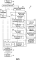
Фиг.1 изображает блок-схему, иллюстрирующую пример конфигурации устройства обработки информации в соответствии с первым вариантом осуществления данного изобретения;1 is a block diagram illustrating an example configuration of an information processing apparatus in accordance with a first embodiment of the present invention;
Фиг.2A-2F изображают виды, иллюстрирующие процесс понижения шума линии;2A-2F are views illustrating a line noise reduction process;
Фиг.3 изображает блок-схему последовательности операций, иллюстрирующую пример последовательности операций устройства обработки информации, показанного на фиг.1;FIG. 3 is a flowchart illustrating an example flowchart of the information processing apparatus shown in FIG. 1;
Фиг.4 изображает диаграмму, иллюстрирующую эффект понижения шума линии в соответствии с первым вариантом осуществления;4 is a diagram illustrating a line noise reduction effect according to a first embodiment;
Фиг.5 изображает блок-схему, иллюстрирующую пример конфигурации устройства обработки информации в соответствии со вторым вариантом осуществления;5 is a block diagram illustrating an example configuration of an information processing apparatus according to a second embodiment;
Фиг.6 изображает блок-схему, иллюстрирующую пример конфигурации устройства обработки информации в соответствии с третьим вариантом осуществления; и6 is a block diagram illustrating an example configuration of an information processing apparatus according to a third embodiment; and
Фиг.7 изображает блок-схему, иллюстрирующую другой пример конфигурации устройства обработки информации в соответствии с третьим вариантом осуществления.7 is a block diagram illustrating another configuration example of an information processing apparatus according to a third embodiment.
ПОДРОБНОЕ ОПИСАНИЕ ИЗОБРЕТЕНИЯDETAILED DESCRIPTION OF THE INVENTION
Теперь, со ссылками на чертежи, будут описаны варианты осуществления данного изобретения.Now, with reference to the drawings, embodiments of the present invention will be described.
ПЕРВЫЙ ВАРИАНТ ОСУЩЕСТВЛЕНИЯFIRST IMPLEMENTATION
Фиг.1 изображает блок-схему, иллюстрирующую пример функциональной конфигурации устройства обработки информации в соответствии с первым вариантом осуществления данного изобретения.1 is a block diagram illustrating an example of a functional configuration of an information processing apparatus according to a first embodiment of the present invention.
Устройство 10 обработки информации включает в себя один или множество встроенных компьютеров. Компьютер включает в себя, например, главное средство управления, такое как центральный процессор (CPU), и средства хранения, такие как ROM (постоянное запоминающее устройство) и RAM (оперативное запоминающее устройство). Компьютер также может включать в себя средство управления графикой, такое как GPU (графический процессор), средство связи, такое как сетевая плата, и средство ввода-вывода, такое как клавиатура, дисплей или тактильная панель. Отметим, что эти составляющие средства соединены посредством шины и управляются путем исполнения программ, хранимых в средствах хранения, средством управления.The
В качестве его функциональной конфигурации отметим, что устройство 10 обработки информации включает в себя блок 20 ввода изображения, блок 23 процесса понижения, блок 24 умножения на коэффициент, сумматор 25, блок 26 хранения обработанного изображения и блок 27 обработки разности. В этом варианте осуществления случайный шум будет приведен в качестве примера шума с пространственными частотами, которые имеют незначительное перекрытие с пространственными частотами объекта, а шум линии (изменения в виде вертикально и горизонтально бегущих полос) будет приведен в качестве примера шума, имеющего пространственные частоты, которые перекрываются с пространственными частотами объекта, но изменяются по временной оси.As its functional configuration, we note that the
Блок 20 ввода изображения обеспечивает ввод извне одного кадра (именуемого далее входным изображением) движущегося изображения (непрерывных кадров). То есть, блок 20 ввода изображения обеспечивает ввод данных изображения текущего кадра. Входное изображение 30 представляет собой, например, двумерное изображение n (строк) × m (столбцов). Входное изображение 30 в соответствии с этим вариантом осуществления содержит шум линии (изменения в виде вертикально и горизонтально бегущих полос) в заданном направлении и объект, как показано заштрихованными участками на фиг.2В. Хотя рассматривается случай, в котором заданное направление является горизонтальным направлением, и в качестве примера будет приведен шум горизонтальной линии в данном варианте осуществления, заданное направление, в сущности, может быть и вертикальным. Хотя двумерное изображение является, например, изображением, захватываемым с помощью рентгеновских лучей, оно не всегда должно быть изображением, захватываемым с помощью рентгеновских лучей.The
Блок 26 хранения обработанного изображения функционирует как запоминающее устройство, которое удерживает (хранит) ранее обработанное выходное изображение (изображение за один кадр до текущего кадра в этом варианте осуществления). Блок 27 обработки разности служит для генерирования изображения разности и включает в себя блок 21 генерирования изображения разности и блок 22 пороговой обработки. Блок 21 генерирования изображения разности генерирует изображение 31 разности между входным изображением 30 и изображением, хранящимся в блоке 26 хранения обработанного изображения (т.е. выходным изображением 35 за один кадр до текущего кадра). Отметим, что при обработке первого кадра в движущемся изображении выдается из изображения 31 разности изображение, идентичное входному изображению 30, потому что изображение за один кадр до этого кадра не существует.The processed
Отметим, что выходное изображение 35 за один кадр до текущего кадра также содержит шум линии в заданном направлении, как показано на фиг.2А, и этот шум обычно изменяется во времени. Поэтому сигналы шума линии генерируются в разных областях в изображениях, показанных на фиг.2А и 2В. Хотя для простоты описания здесь в качестве примера приводится случай, в котором изображения, показанные на фиг.2А и 2В, имеют сигналы шума линии с той же амплитудой, сигналы шума линии, генерируемые в действительности в этих изображениях, не обязательно должны иметь одну и ту же амплитуду в пространстве и времени. Изображение 31 разности, генерируемое блоком 31 генерирования изображения разности, содержит шум линии (заштрихованные участки), шум линии (участки с противоположной штриховкой) с амплитудой, противоположной по знаку амплитуде первого шума, и область, в которой объект переместился, как показано на фиг.2С.Note that the
Блок 22 пороговой обработки осуществляет пороговую обработку для изображения 31 разности, генерируемого блоком 21 генерирования изображения разности. Более конкретно, блок 22 пороговой обработки вычисляет абсолютное значение каждого пикселя в изображении 31 разности и осуществляет пороговую обработку для абсолютного значения с использованием заданного значения. Например, заданное значение устанавливается несколько большим, чем стандартное отклонение шума линии. Если результат обработки показывает, что присутствует пиксель с абсолютным значением, которое превышает заданное значение, то определяют, что этот пиксель отображает движение объекта, и этот пиксель заменяют на «0» или умножают на коэффициент, меньший чем «1». Изображение 32 разности (после пороговой обработки), получаемое посредством этой обработки, предполагает состояние, в котором движение объекта устранено, как показано на фиг.2D.The
Изображение 31 разности содержит случайный шум для каждого пикселя в больших количествах, так что иногда трудно выявить различия между движением и случайным шумом в этом изображении. В этом случае блок 22 пороговой обработки может обрабатывать изображение 31 разности с использованием, например, двумерного сглаживающего фильтра (пространственной фильтрации) перед вышеупомянутой пороговой обработкой. То есть вышеупомянутую пороговую обработку осуществляют после понижения случайного шума. При условии этой обработки можно понизить частоту ошибочного различения между случайным шумом и движением, тем самым позволяя определение движения с повышенной точностью. Такая пространственная фильтрация эффективна, когда разность по пространственной частоте между шумом и объектом мала. Диапазон фильтрации этого пространственного фильтра определяется на основании пространственной частоты объекта, получаемой из блока анализа частоты (не показан). Таким образом, шум можно понизить, при этом сохраняя информацию об объекте в изображении. Блок анализа частоты анализирует частоту объекта с использованием известного способа, такого, как преобразование Фурье. Кроме того, в качестве пространственной частоты объекта можно использовать значение, которое экспериментально определяют заранее.The
Блок 23 процесса понижения функционирует как блок генерирования изображения шума, который генерирует изображение шума линии. То есть, блок 23 процесса понижения понижает изображение 32 разности (после пороговой обработки) в заданном направлении (таком же направлении, как направление, в котором идет шум линии), тем самым генерируя изображение 33 разности (после процесса понижения), которое содержит составляющие шума в качестве своих принципиальных составляющих. Изображение 33 разности (после процесса понижения) понижают в заданном направлении (горизонтальном направлении). Во время этого процесса понижения соответствующие пиксели в изображении (изображении 32 разности (после пороговой обработки)), например, линейно соединяются друг с другом в заданном направлении (горизонтальном направлении в этом варианте осуществления). При линейном соединении изображение 32 разности (после пороговой обработки) подвергают горизонтальному понижению, принимая среднее из k пикселей (k≥2) за один пиксель. Процесс понижения, например, может быть общепринятым процессом прореживания. При осуществлении этого процесса понижения, случайный шум усредняют и тем самым понижают, так что генерируется изображение 33 разности (после процесса понижения), которое содержит составляющие шума в качестве своих принципиальных составляющих, как показано на фиг.2Е.The
Блок 24 умножения на коэффициент умножает каждый пиксель в изображении 33 разности (после процесса понижения) на коэффициент α для генерирования изображения 34 разности (после умножения на коэффициент). Коэффициент α равен, например, значению, меньшему чем «1» (α<1). Частотные характеристики рекурсивного фильтра во временном направлении определяются в соответствии со значением этого коэффициента. Поскольку частотные характеристики этого фильтра во временном направлении определяются в соответствии с величиной коэффициента α, значение коэффициента α экспериментально определяют так, чтобы можно было отделить шум от движения объекта (например, тела человека). В альтернативном варианте, возможно выделить объект и определить значение коэффициента α из движения краевой части во временном направлении. Отметим, что поскольку шум линии временно сдвигается относительно движения объекта (например, тела человека), его следует подавлять при определении фильтра во временной области.The
Сумматор 25 складывает изображение 34 разности (после умножения на коэффициент) с входным изображением 30. Процесс сложения можно осуществлять после интерполяции пониженного изображения до размера входного изображения 30 с использованием широко известного способа интерполяции.The
Значение Xt(i) пикселя входного изображения 30, значение Yt(i) пикселя выходного изображения 35, основанного на входном изображении 30, значение Yt-1(i) пикселя выходного изображения за один кадр до текущего кадра и коэффициент α, на который блок 24 умножения на коэффициент умножает каждый пиксель, имеют следующую связь:The pixel value Xt (i) of the
где F - функция, отображающая, например, пороговую обработку и процесс горизонтального понижения.where F is a function that displays, for example, threshold processing and the horizontal lowering process.
В результате, шум линии во входном изображении 30 сглаживается во временном направлении в соответствии с коэффициентом α, как показано на фиг.2F. Заштрихованные участки на фиг.2F обозначают состояние, в котором шум линии частично остается, но несмотря на это, остаточный шум, обозначенный заштрихованными участками, сглаживается при дальнейшей обработке кадров.As a result, line noise in the
Таким образом, в этом варианте осуществления избирательно осуществляется рекурсивная фильтрация для составляющих шума линии, что ведет к подавлению составляющих шума линии в серии/последовательности движущихся изображений, получаемых в результате (то есть, множества выходных изображений 35).Thus, in this embodiment, recursive filtering is selectively performed for line noise components, which leads to suppression of line noise components in a series / sequence of moving images resulting from (i.e., a plurality of output images 35).
Далее, со ссылками на фиг.3, будет описан пример последовательности процесса понижения шума линии в устройстве 10 обработки информации, показанном на фиг.1.Next, with reference to FIG. 3, an example of a sequence of a line noise reduction process in the
Этот процесс начинается, когда устройство 10 обработки информации использует блок 20 ввода изображения, чтобы осуществить ввод извне (S101) одного кадра (входного изображения 30) движущегося изображения. Ввод движущегося изображения можно осуществить, например, через сеть или носитель информации, такой, как карта памяти.This process begins when the
Затем устройство 10 обработки информации использует блок 21 генерирования изображения разности для генерирования (S102) изображения разности (изображения 31 разности) между входным изображением 30 и изображением непосредственно перед входным изображением 30 (т.е. за один кадр до него). Отметим, что изображение за один кадр до входного изображения 30 получают из блока 26 хранения обработанного изображения.Then, the
После завершения генерирования изображения 31 разности, устройство 10 обработки информации использует блок 22 пороговой обработки для осуществления пороговой обработки (S103) для генерированного изображения 31 разности. После этого устройство 10 обработки информации использует блок 23 осуществления процесса понижения, чтобы понизить (S104) изображение 32 разности (после пороговой обработки) в заданном направлении (горизонтальном направлении в этом примере).After completion of generating the
После завершения процесса понижения, устройство 10 обработки информации использует блок 24 умножения на коэффициент, чтобы умножить (S105) каждый пиксель в изображении 33 разности (после процесса понижения) на коэффициент (например, значение, меньшее чем «1»). Частотные характеристики рекурсивного фильтра во временном направлении определяются в соответствии со значением этого коэффициента, как описано выше.After the reduction process is completed, the
И, наконец, устройство 10 обработки информации использует сумматор 25 для сложения (S106) изображения 34 разности (после умножения на коэффициент) с входным изображением 30, введенным на этапе S101. Таким образом, после сложения, при вычитании шума линии из входного изображения 30 получается выходное изображение 35 (т.е. изображение с меньшим шумом линии).And finally, the
Далее, со ссылками на фиг.4, будет описан эффект понижения шума линии в этом варианте осуществления.Next, with reference to FIG. 4, a line noise reduction effect in this embodiment will be described.
Обращаясь к фиг.4, отмечаем, что абсцисса указывает количество кадров в движущемся изображении, а ордината обозначает спектр мощности шума линии. Спектр мощности вычисляют с использованием движущегося изображения с шагом пикселей, составляющим 300 мкм, и размером 1000×1000 пикселей. Следовательно, частота Найквиста составляет 1,56 пар линий на миллиметр.Turning to figure 4, we note that the abscissa indicates the number of frames in a moving image, and the ordinate indicates the power spectrum of the noise line. The power spectrum is calculated using a moving image with a pixel pitch of 300 μm and a size of 1000 × 1000 pixels. Therefore, the Nyquist frequency is 1.56 pairs of lines per millimeter.
Шум линии, подвергнутый анализу спектра мощности, сводится к диапазону частот, соответствующему 7 парам линий на метр, так что процесс понижения в этом варианте осуществления дает эффект до диапазона частот, в котором трудно понизить шум линии для процесса понижения шума линии, использующего обычный пространственный фильтр. Как можно увидеть из сравнения между спектрами мощности в «процесс отсутствует (пунктирная линия)» и «этот вариант осуществления (сплошная линия)», мощность шума линии понижается до половины или менее в этом варианте осуществления.The noise of the line subjected to the power spectrum analysis is reduced to a frequency range corresponding to 7 pairs of lines per meter, so the reduction process in this embodiment has an effect to the frequency range in which it is difficult to reduce the noise of the line for the noise reduction process of the line using a conventional spatial filter . As can be seen from the comparison between the power spectra in “no process (dashed line)” and “this embodiment (solid line)”, the noise power of the line is reduced to half or less in this embodiment.
Второй вариант осуществленияSecond Embodiment
Далее будет описан второй вариант осуществления. Фиг.5 изображает блок-схему, иллюстрирующую пример функциональной конфигурации устройства 10 обработки информации в соответствии со вторым вариантом осуществления. Отметим, что те же ссылочные позиции обозначают составляющие элементы, которые демонстрируют те же функции, что и в функциональной конфигурации, показанной на фиг.1, на которую сделаны ссылки в описании первого варианта осуществления, поэтому их описание иногда будет опущено. Описано будет главным образом различие между первым и вторым вариантами осуществления.Next, a second embodiment will be described. 5 is a block diagram illustrating an example of a functional configuration of an
Устройство 10 обработки информации включает в себя блок 20 ввода изображения, блок 24 умножения на коэффициент, сумматор 25, блок 26 хранения обработанного изображения, блок 27 обработки разности и блок 28 одномерной фильтрации. То есть, устройство 10 обработки информации получено путем исключения блока 23 процесса понижения из конфигурации, показанной на фиг.1, на которую делались ссылки при описании первого варианта осуществления, и добавления блока 28 одномерной фильтрации в эту конфигурацию.The
Блок 28 одномерной фильтрации функционирует как блок генерирования изображения шума, который генерирует изображение шума линии. То есть, блок 28 одномерной фильтрации осуществляет одномерную сглаживающую фильтрацию для изображения 32 разности в заданном направлении (таком же направлении, как то, в котором идет шум линии), тем самым генерируя изображение 36 разности (после фильтрации), которое содержит составляющие шума линии в качестве его принципиальных составляющих. Одномерный сглаживающий фильтр может быть широко известным фильтром, таким, как усредняющий фильтр, фильтр Гаусса или медианный фильтр. При этой фильтрации случайный шум усредняется и тем самым понижается, так что генерируется изображение 36 разности (после фильтрации), которое содержит составляющие шума линии в качестве своих принципиальных составляющих.The one-
После фильтрации устройство 10 обработки информации использует блок 24 умножения на коэффициент, чтобы умножить изображение 36 разности (после фильтрации) на коэффициент и использует сумматор 25 для сложения изображения 37 разности (после умножения на коэффициент) с входным изображением 30. Таким образом, во втором варианте осуществления, как и в первом варианте осуществления, можно избирательно проводить рекурсивную фильтрацию шума линии.After filtering, the
Отметим, что работа устройства 10 обработки информации в соответствии со вторым вариантом осуществления следует той же последовательности операций, что и на фиг.3, на которую делались ссылки при описании первого варианта осуществления, а ее описание со ссылками на чертежи приведено не будет. Различие между первым и вторым вариантами осуществления заключается в том, что в последнем на этапе S104 осуществляют вышеописанную одномерную фильтрацию вместо процесса горизонтального понижения в первом.Note that the operation of the
Третий вариант осуществленияThird Embodiment
Далее будет описан третий вариант осуществления, в котором процессы понижения шума, описанные в первом и втором вариантах осуществления, использующие пространственный фильтр, как описано в первоисточнике 1, осуществляются в сочетании, пример которого и приводится в третьем варианте осуществления.Next, a third embodiment will be described in which the noise reduction processes described in the first and second embodiments using the spatial filter, as described in the original source 1, are carried out in combination, an example of which is given in the third embodiment.
На фиг.6 представлена блок-схема, иллюстрирующая пример функциональной конфигурации устройства 10 обработки информации в соответствии с третьим вариантом осуществления. Отметим, что те же ссылочные позиции обозначают составляющие элементы, которые демонстрируют те же функции, что и в функциональной конфигурации, показанной на фиг.1. Описано будет главным образом различие между первым и третьим вариантами осуществления.6 is a block diagram illustrating an example of a functional configuration of an
В дополнение к конфигурации, показанной на фиг.1, на которую сделаны ссылки в описании первого варианта осуществления, устройство 10 обработки информации включает в себя первый блок 41 пространственной фильтрации, второй блок 42 пространственной фильтрации, блок 43 обнаружения и блок 44 управления.In addition to the configuration shown in FIG. 1, referred to in the description of the first embodiment, the
Первый блок 41 пространственной фильтрации осуществляет процесс понижения шума, который использует пространственный фильтр, для входного изображения 30. Когда, например, перемещение объекта велико, а влияние запаздывания изображения существенно, процессы понижения шума, описанные в первом и втором вариантах осуществления, проводятся после процесса понижения шума, который использует пространственный фильтр, и осуществляется первым блоком 41 пространственной фильтрации. В этом случае, поскольку заданное значение (порог), используемое для блока 22 пороговой обработки, можно сделать малым, можно получить изображение с малым остаточным изображением. То есть, процесс понижения шума посредством первого блока 41 пространственной фильтрации эффективен, когда перемещение объекта велико, а влияние остаточного изображения существенно. Отметим, что в процессе понижения шума, который предусматривает использование пространственного фильтра, возможно применение обычных способов (см., например, источник 1), а их описание приведено не будет.The first
Второй блок 42 пространственной фильтрации осуществляет процесс понижения шума, который использует пространственный фильтр, для изображения, обработанного сумматором 25. То есть, второй блок 42 пространственной фильтрации осуществляет тот же процесс, что и первый блок 41 пространственной фильтрации, хотя они обрабатывают разные изображения. Например, после осуществления процессов понижения шума, описанных в первом и втором вариантах осуществления, второй блок 42 пространственной фильтрации анализирует составляющие пространственной частоты остаточного шума линии. После этого второй блок 42 пространственной фильтрации осуществляет процесс понижения шума, который использует пространственный фильтр для пространственных частот, получаемых путем этого анализа. В этом случае нет необходимости проводить пространственную фильтрацию в неоправданно широком диапазоне. Например, как в случае изображения, описывающего природу, важна пространственная частотная составляющая низкой частоты. Таким образом, возможно предотвратить размытость объекта, если процесс понижения шума посредством второго блока 42 пространственной фильтрации ограничен по составляющей пространственной частоты.The second spatial filtering
Блок 43 обнаружения обнаруживает интенсивность шума линии и движение объекта, причем оба во входном изображении 30. Отметим, что для обнаружения интенсивности шума линии и движения объекта может использоваться обычный способ (см., например, источник 2), описание которого не приводится.The
В соответствии с конфигурацией, описанной выше, процесс понижения шума, который использует пространственный фильтр, осуществляется до или после воплощения процесса понижения шума, описанного в первом и втором вариантах осуществления, в соответствии с интенсивностью шума линии и движением объекта. Таким образом, процессы понижения шума линии осуществляются адаптивно, так что можно получить малое остаточное изображение и малую размытость движущегося объекта. То есть, можно понизить шум, подавляя при этом влияние, которое излучение оказывает на объект.According to the configuration described above, the noise reduction process that uses the spatial filter is carried out before or after the implementation of the noise reduction process described in the first and second embodiments, in accordance with the line noise intensity and the movement of the object. Thus, the line noise reduction processes are carried out adaptively, so that a small afterimage and a small blur of a moving object can be obtained. That is, noise can be reduced while suppressing the effect that radiation has on the object.
Конфигурация устройства 10 обработки информации в соответствии с третьим вариантом осуществления, показанная на фиг.6, является лишь примером и может быть должным образом изменена. Например, блок 43 обнаружения и блок 44 управления не являются обязательными составляющими элементами и могут быть исключены. Если эти составляющие элементы исключены, процессы, осуществляемые первым блоком 41 пространственной фильтрации и вторым блоком 42 пространственной фильтрации, могут осуществляться одинаково. Кроме того, например, не обязательно предусматривать и первый блок 41 пространственной фильтрации, и второй блок 42 пространственной фильтрации, и можно предусмотреть лишь один из них.The configuration of the
Более того, как указано в первоисточнике 2, можно позаимствовать конфигурацию, которая, например, осуществляет первые процессы понижения шума, как описано в первом и втором вариантах осуществления, и второй процесс понижения шума, который использует пространственный фильтр, при изменении соотношения процессов. Эту конфигурацию можно реализовать путем заимствования конфигурации, показанной, например, на фиг.7. То есть, блок 44 управления осуществляет первый процесс понижения шума посредством блока 45 рекурсивной фильтрации и второй процесс понижения шума, который использует пространственный фильтр, при изменении соотношения процессов, в соответствии с результатами обнаружения, полученными посредством блока 43 обнаружения. Отметим, что изменение в соотношении процессов имеет место на основании интенсивности шума линии и движения объекта. В этом случае процессы понижения шума осуществляются адаптивно, так что можно получить движущееся изображение с малым остаточным изображением и малой размытостью объекта.Moreover, as indicated in the original source 2, you can borrow a configuration that, for example, carries out the first noise reduction processes, as described in the first and second embodiments, and the second noise reduction process that uses a spatial filter, when changing the ratio of processes. This configuration can be implemented by borrowing the configuration shown, for example, in Fig.7. That is, the
Хотя выше были описаны примерные варианты осуществления данного изобретения, данное изобретение не ограничивается вариантами осуществления, описанными выше и показанными на чертежах, и может быть надлежащим образом модифицировано и воплощено на практике без отклонения от объема данного изобретения.Although exemplary embodiments of the present invention have been described above, the present invention is not limited to the embodiments described above and shown in the drawings, and can be appropriately modified and put into practice without departing from the scope of the present invention.
В качестве примера отметим, что хотя случай, в котором изображение за один кадр до текущего кадра используется при обработке разности, приведен как пример в первом и втором вариантах осуществления, данное изобретение этим не ограничивается, и можно использовать, например, изображение более чем за один кадр до текущего кадра или множество изображений двух или более разных кадров. Например, это зависит от составляющей частоты и может предусматривать расположение ее в незанятом интервале времени, если предполагается использование обычного пространственного фильтра и приходится иметь дело с многочисленными кадрами.As an example, we note that although the case in which the image one frame before the current frame is used in the difference processing is shown as an example in the first and second embodiments, the present invention is not limited to this, and, for example, an image of more than one can be used frame to the current frame or multiple images of two or more different frames. For example, it depends on the component of the frequency and may provide for its location in an unoccupied time interval, if it is assumed to use a conventional spatial filter and have to deal with multiple frames.
В качестве другого примера отметим, что хотя в вариантах осуществления с первого по третий лишь данные изображения кадра, обработанного до текущего кадра, умножаются на коэффициент α (кратное коэффициенту α), данное изобретение этим не ограничивается. Например, можно умножать данные изображения текущего кадра на значение, соответствующее коэффициенту α, на который умножаются данные изображения кадра, обработанного перед текущим кадром.As another example, note that although in the first through third embodiments, only image data of a frame processed before the current frame is multiplied by a coefficient α (a multiple of the coefficient α), the present invention is not limited to this. For example, you can multiply the image data of the current frame by a value corresponding to the coefficient α by which the image data of the frame processed before the current frame is multiplied.
Данное изобретение можно воплотить, например, в виде системы, устройства, способа и программы или носителя информации. Более конкретно, данное изобретение может быть применено к системе, включающей в себя множество устройств, или к прибору, включающему в себя лишь одно устройство.This invention can be embodied, for example, in the form of a system, device, method and program or information carrier. More specifically, the present invention can be applied to a system including a plurality of devices, or to a device including only one device.
Другие варианты осуществленияOther options for implementation
Аспекты данного изобретения также можно реализовать посредством компьютера системы или устройства (или устройств, таких как центральный процессор или микропроцессор), который считывает и исполняет программу, записанную в запоминающем устройстве, для выполнения функций вышеописанного варианта (вышеописанных вариантов) осуществления, и посредством способа, этапы которого осуществляются компьютером системы или устройства посредством, например, считывания и исполнения программы, записанной в запоминающем устройстве, для выполнения функций вышеописанного варианта (вышеописанных вариантов) осуществления. С этой целью на компьютер устанавливают программу, например, через сеть или с носителя информации разных типов, служащего в качестве запоминающего устройства (например, считываемого компьютером носителя информации).Aspects of the present invention can also be implemented by a computer system or device (or devices, such as a central processor or microprocessor) that reads and executes a program recorded in a storage device to perform the functions of the above embodiment (the above options) implementation, and by the method, the steps which is carried out by a computer of a system or device by, for example, reading and executing a program recorded in a memory device for executing share the above option (the above options) implementation. For this purpose, a program is installed on a computer, for example, through a network or from a storage medium of various types serving as a storage device (for example, a storage medium read by a computer).
Хотя данное изобретение описано со ссылками на примерные варианты осуществления, следует понимать, что изобретение не ограничивается описанными примерными вариантами осуществления. Объем нижеследующей формулы изобретения следует рассматривать в самом широком толковании, так чтобы охватывать все такие модификации и эквивалентные конструкции и функции.Although the present invention has been described with reference to exemplary embodiments, it should be understood that the invention is not limited to the described exemplary embodiments. The scope of the following claims should be construed in their broadest interpretation so as to encompass all such modifications and equivalent structures and functions.
Claims (22)
средство (41, 42) пространственной фильтрации, выполненные с возможностью осуществления пространственной фильтрации в диапазоне частот, основанном на пространственной частоте объекта, для данных изображения текущего кадра, и
средство (45) рекурсивной фильтрации, выполненное с возможностью осуществления рекурсивной фильтрации путем получения данных изображения, которые обработаны до текущего кадра, из запоминающего устройства, умножения полученных данных изображения на коэффициент α (α<1), сложения данных изображения, умноженных на коэффициент α, с данными изображения текущего кадра после пространственной фильтрации, и сохранения данных изображения после сложения в запоминающем устройстве.1. Device (10) for processing information, containing:
spatial filtering means (41, 42) configured to perform spatial filtering in a frequency range based on the spatial frequency of the object for image data of the current frame, and
recursive filtering means (45) configured to perform recursive filtering by obtaining image data that has been processed before the current frame from a storage device, multiplying the obtained image data by a coefficient α (α <1), adding image data multiplied by a coefficient α, with image data of the current frame after spatial filtering, and storing image data after addition to the storage device.
средство (43) обнаружения, выполненное с возможностью обнаружения интенсивности шума линии и движения объекта, причем оба в данных изображения текущего кадра, и
средство (44) управления, выполненное с возможностью осуществления процесса посредством упомянутых средств пространственной фильтрации и процесса посредством упомянутого средства рекурсивной фильтрации во время переключения процессов с одного на другой в соответствии с результатами обнаружения, полученными упомянутым средством обнаружения.3. The device according to claim 1, additionally containing:
detection means (43) configured to detect line noise intensity and object motion, both in the image data of the current frame, and
control means (44) configured to carry out the process by the said spatial filtering means and the process by the said recursive filtering means during switching processes from one to another in accordance with the detection results obtained by said detection means.
средство (43) обнаружения, выполненное с возможностью обнаружения интенсивности шума линии и движения объекта, причем оба в данных изображения текущего кадра, и
средство (44) управления, выполненное с возможностью осуществления процесса посредством упомянутых средств пространственной фильтрации и процесса посредством упомянутого средства рекурсивной фильтрации во время изменения соотношения процессов между ними в соответствии с результатами обнаружения, полученными упомянутым средством обнаружения.4. The device according to claim 1, additionally containing:
detection means (43) configured to detect line noise intensity and object motion, both in the image data of the current frame, and
control means (44) configured to carry out the process by means of said spatial filtering means and a process by said recursive filtering means while changing the ratio of processes between them in accordance with the detection results obtained by said detection means.
средство (27) обработки разности, выполненное с возможностью генерирования изображения разности между данными изображения текущего кадра и данными изображения, которые обработаны до текущего кадра,
средство (23) генерирования изображения шума, выполненное с возможностью генерирования изображения шума линии из изображения разности, сгенерированного средством обработки разности,
блок (24) умножения на коэффициент, выполненный с возможностью умножения каждого пикселя в изображении шума линии, сгенерированного средством генерирования шума, на коэффициент α, и
сумматор (25), выполненный с возможностью сложения изображения шума линии, умноженного на коэффициент α посредством блока умножения на коэффициент, с данными изображения текущего кадра и сохранения данных изображения после сложения в запоминающем устройстве.5. The device according to claim 1, in which the said recursive filtering means includes:
difference processing means (27) configured to generate a difference image between image data of the current frame and image data that are processed prior to the current frame,
noise image generating means (23) configured to generate a line noise image from a difference image generated by the difference processing means,
a multiplication unit (24) by a coefficient configured to multiply each pixel in the noise image of the line generated by the noise generating means by a coefficient α, and
an adder (25), configured to add the image of the noise of the line multiplied by the coefficient α by the unit of multiplication by the coefficient, with the image data of the current frame and save the image data after addition to the storage device.
осуществляют пространственную фильтрацию в диапазоне частот, основанном на пространственной частоте объекта, для данных изображения текущего кадра, и
осуществляют рекурсивную фильтрацию путем получения данных изображения, которые обработаны до текущего кадра, из запоминающего устройства, умножения полученных данных изображения на коэффициент α (α<1), сложения данных изображения, умноженных на коэффициент α, с данными изображения текущего кадра после пространственной фильтрации, и сохранения данных изображения после сложения в запоминающем устройстве.9. A processing method for an information processing device, comprising the steps of:
performing spatial filtering in the frequency range based on the spatial frequency of the object, for image data of the current frame, and
carry out recursive filtering by obtaining image data that has been processed before the current frame from the storage device, multiplying the obtained image data by a coefficient α (α <1), adding image data multiplied by a coefficient α with image data of the current frame after spatial filtering, and storing image data after addition to the storage device.
средство обработки разности, выполненное с возможностью генерирования изображения разности между изображением текущего кадра и обработанным изображением, хранимым в памяти;
средство отделения, выполненное с возможностью отделения шума изображения на основании изображения разности;
сумматор, выполненный с возможностью смешения текущего изображения кадра и изображения шума с определенным коэффициентом смешения;
средство хранения, выполненное с возможностью сохранения изображения, полученного посредством сумматора, как нового обработанного изображения, в памяти.11. An information processing device that performs recursive filtering processing for a particular frame image in a moving image based on another frame image in a moving image, and which receives the processed image after recursive filtering processing, the device comprises:
difference processing means configured to generate a difference image between the image of the current frame and the processed image stored in the memory;
separation means configured to separate image noise based on the difference image;
an adder configured to mix the current frame image and the noise image with a certain mixing coefficient;
storage means configured to store the image obtained by the adder as a new processed image in memory.
средство пространственной фильтрации, выполненное с возможностью выполнения пространственной фильтрации для текущего изображения кадра на основании информации об объекте перед генерированием изображения разности, и
средство обработки понижения движения, выполненное с возможностью удаления информации о движении объекта в изображении разности, сгенерированном средством обработки разности после обработки пространственной фильтрацией,
при этом указанное средство отделения отделяет изображение шума от изображения в котором информация движения понижается.14. The device according to any one of paragraphs.11-13, further comprising:
spatial filtering means configured to perform spatial filtering for the current image of the frame based on information about the object before generating the difference image, and
motion reduction processing means configured to delete information about the movement of an object in a difference image generated by the difference processing means after spatial filtering,
wherein said separation means separates the noise image from the image in which the motion information is reduced.
при этом, по меньшей мере, один из параметра обработки пространственной фильтрации посредством средства пространственной фильтрации и определенного коэффициента смешения посредством сумматора изменяют на основании определенного соотношения процессов.16. The device according to 14, further comprising a means of determining, configured to determine the ratio of processes between processing by spatial filtering and processing by an adder based on at least one of the motion information and information about the image object of the current frame,
wherein at least one of the spatial filtering processing parameter by the spatial filtering means and the determined mixing coefficient by the adder is changed based on a certain process ratio.
средство обработки пространственной фильтрации, выполненное с возможностью осуществления обработки понижения шума для текущего изображения кадра, использующее пространственный фильтр на основании информации об объекте, и
средство обработки рекурсивной фильтрации, выполненное с возможностью понижения шума текущего изображения кадра на основании информации о шуме, выделенном из различия изображения между текущим изображением кадра и обработанным изображением, к которому применялась обработка рекурсивной фильтрации.19. An information processing device that reduces the noise of a frame image in a moving image using a spatial filter and a recursive filter, the device comprises:
spatial filtering processing means configured to perform noise reduction processing for a current frame image using a spatial filter based on information about an object, and
recursive filtering processing means configured to reduce the noise of the current frame image based on noise information extracted from the image difference between the current frame image and the processed image to which the recursive filtering processing has been applied.
генерируют изображение разности между изображением текущего кадра и обработанным изображением, хранимым в памяти;
отделяют шум изображения на основании изображения разности;
смешивают текущее изображения кадра и изображение шума путем сложения изображения шума и текущего изображения, используя определенный коэффициент смешения; и
сохраняют изображение, полученное посредством сумматора, как новое обработанное изображение, в памяти.21. An information processing method for an information processing device that performs recursive filtering processing for a specific frame image in a moving image based on another frame image in a moving image, and which receives the processed image after recursive filtering processing, the method comprises the steps of:
generating an image of the difference between the image of the current frame and the processed image stored in memory;
separating image noise based on the difference image;
mixing the current frame image and the noise image by adding the noise image and the current image using a specific mixing coefficient; and
save the image obtained by the adder as a new processed image in memory.
осуществляют обработку понижения шума для текущего изображения кадра с использованием пространственного фильтра на основании информации об объекте, и
понижают шум текущего изображения кадра на основании информации о шуме, выделенном из различия изображения между текущим изображением кадра и обработанным изображением, к которому применялась обработка рекурсивной фильтрации. 22. An information processing method for an information processing device that reduces the noise of a frame image in a moving image using a spatial filter and a recursive filter, the method comprises the steps of:
performing noise reduction processing for the current image of the frame using a spatial filter based on information about the object, and
reduce the noise of the current frame image based on noise information extracted from the image difference between the current frame image and the processed image to which recursive filtering processing has been applied.
Applications Claiming Priority (2)
| Application Number | Priority Date | Filing Date | Title |
|---|---|---|---|
| JP2009-293208 | 2009-12-24 | ||
| JP2009293208A JP5543194B2 (en) | 2009-12-24 | 2009-12-24 | Information processing apparatus, processing method, and program |
Related Child Applications (1)
| Application Number | Title | Priority Date | Filing Date |
|---|---|---|---|
| RU2012158155/08A Division RU2526761C2 (en) | 2009-12-24 | 2010-12-23 | Information processing device, processing method and computer-readable storage medium |
Publications (2)
| Publication Number | Publication Date |
|---|---|
| RU2010152848A RU2010152848A (en) | 2012-06-27 |
| RU2480821C2 true RU2480821C2 (en) | 2013-04-27 |
Family
ID=43928883
Family Applications (2)
| Application Number | Title | Priority Date | Filing Date |
|---|---|---|---|
| RU2012158155/08A RU2526761C2 (en) | 2009-12-24 | 2010-12-23 | Information processing device, processing method and computer-readable storage medium |
| RU2010152848/08A RU2480821C2 (en) | 2009-12-24 | 2010-12-23 | Information processing device, processing method and computer-readable storage medium |
Family Applications Before (1)
| Application Number | Title | Priority Date | Filing Date |
|---|---|---|---|
| RU2012158155/08A RU2526761C2 (en) | 2009-12-24 | 2010-12-23 | Information processing device, processing method and computer-readable storage medium |
Country Status (6)
| Country | Link |
|---|---|
| US (1) | US8655034B2 (en) |
| EP (1) | EP2357607B1 (en) |
| JP (1) | JP5543194B2 (en) |
| KR (1) | KR101432864B1 (en) |
| CN (1) | CN102156962B (en) |
| RU (2) | RU2526761C2 (en) |
Families Citing this family (20)
| Publication number | Priority date | Publication date | Assignee | Title |
|---|---|---|---|---|
| JP6214128B2 (en) | 2010-11-22 | 2017-10-18 | キヤノン株式会社 | Image processing apparatus, image processing method, and storage medium |
| JP5864958B2 (en) * | 2011-08-31 | 2016-02-17 | キヤノン株式会社 | Image processing apparatus, image processing method, program, and computer recording medium |
| JP6122269B2 (en) * | 2011-12-16 | 2017-04-26 | キヤノン株式会社 | Image processing apparatus, image processing method, and program |
| JP6000659B2 (en) | 2012-06-01 | 2016-10-05 | キヤノン株式会社 | Information processing apparatus, information processing method, and program |
| JP6312401B2 (en) | 2012-11-30 | 2018-04-18 | キヤノン株式会社 | Image processing apparatus, image processing method, and program |
| JP6242230B2 (en) * | 2014-02-12 | 2017-12-06 | オリンパス株式会社 | Image processing apparatus, endoscope apparatus, operation method of image processing apparatus, and image processing program |
| JP6497912B2 (en) | 2014-12-01 | 2019-04-10 | キヤノン株式会社 | Image processing apparatus, radiation imaging system, control method, and program |
| US11132769B2 (en) * | 2016-03-23 | 2021-09-28 | Koninklijke Philips N.V. | Image quality by two pass temporal noise reduction |
| RU2653100C1 (en) * | 2017-02-09 | 2018-05-07 | Акционерное общество "Российская корпорация ракетно-космического приборостроения и информационных систем" (АО "Российские космические системы") | Method for obtaining and processing images of earth's remote sensing deformed by turbulent air |
| JP7080025B2 (en) | 2017-09-01 | 2022-06-03 | キヤノン株式会社 | Information processing equipment, information processing methods and programs |
| US11751835B2 (en) * | 2017-09-14 | 2023-09-12 | Shimadzu Corporation | Radiographic imaging apparatus |
| JP7093233B2 (en) | 2018-06-07 | 2022-06-29 | キヤノン株式会社 | Radiography equipment, radiography methods and programs |
| WO2020003744A1 (en) | 2018-06-27 | 2020-01-02 | キヤノン株式会社 | Radiographic imaging apparatus, radiographic imaging method, and program |
| JP6821093B2 (en) * | 2018-06-29 | 2021-01-27 | 三菱電機株式会社 | Imaging device and line fluctuation noise reduction device |
| JP7091919B2 (en) * | 2018-08-02 | 2022-06-28 | 株式会社島津製作所 | Radiation imaging device |
| JP7169853B2 (en) | 2018-11-09 | 2022-11-11 | キヤノン株式会社 | Image processing device, radiation imaging device, and image processing method |
| JP7246281B2 (en) | 2019-08-02 | 2023-03-27 | キヤノン株式会社 | IMAGE PROCESSING APPARATUS AND CONTROL METHOD THEREOF, RADIATION IMAGING APPARATUS, AND PROGRAM |
| KR102448069B1 (en) * | 2022-05-27 | 2022-09-27 | 주식회사 디알텍 | Method and apparatus for reducing noise of image obtained by radiography |
| KR20240102535A (en) | 2022-12-26 | 2024-07-03 | 주식회사 디알텍 | Image processing method and apparatus for reducing noise of image obtained by radiography |
| CN116385280B (en) * | 2023-01-09 | 2024-01-23 | 爱芯元智半导体(上海)有限公司 | Image noise reduction system and method and noise reduction neural network training method |
Citations (5)
| Publication number | Priority date | Publication date | Assignee | Title |
|---|---|---|---|---|
| US4847909A (en) * | 1987-04-30 | 1989-07-11 | Shimadzu Corporation | Apparatus for processing an X-ray image |
| RU2125344C1 (en) * | 1990-06-25 | 1999-01-20 | Квэлкомм Инкорпорейтед | System and method for modulating data signals in cellular telephone communication system with coded multiple-access sharing |
| RU2189700C2 (en) * | 1995-12-12 | 2002-09-20 | РКА Лайсенсинг Корпорейшн | Device for compression of videosignal presenting image and device for fixation of noise filtration in signal |
| EP1267993B1 (en) * | 2000-03-22 | 2005-01-05 | Medtronic, Inc. | Apparatus for diagnosis and treatment of arrhythmias |
| EP1617434A1 (en) * | 2003-04-23 | 2006-01-18 | Matsushita Electric Industrial Co., Ltd. | Recording medium, reproducing apparatus, recording method, reproducing program, and reproducing method |
Family Cites Families (34)
| Publication number | Priority date | Publication date | Assignee | Title |
|---|---|---|---|---|
| JPS6065679A (en) | 1983-09-21 | 1985-04-15 | Hitachi Ltd | Line noise suppressing circuit |
| JPH01273487A (en) * | 1988-04-26 | 1989-11-01 | Shimadzu Corp | Digital x-ray device |
| JP3159465B2 (en) * | 1991-05-17 | 2001-04-23 | 株式会社東芝 | Image display device |
| EP0588934B1 (en) * | 1991-06-14 | 2000-03-01 | GUISSIN, David | Apparatus and method for smoothing images |
| US5799111A (en) * | 1991-06-14 | 1998-08-25 | D.V.P. Technologies, Ltd. | Apparatus and methods for smoothing images |
| JP2898124B2 (en) * | 1991-07-10 | 1999-05-31 | 浜松ホトニクス株式会社 | Speckle image displacement measuring device |
| JP3158371B2 (en) * | 1992-04-24 | 2001-04-23 | ソニー株式会社 | Noise reducer |
| JPH0647035A (en) * | 1992-07-31 | 1994-02-22 | Shimadzu Corp | Image processing system |
| FR2736182A1 (en) * | 1995-06-30 | 1997-01-03 | Philips Electronique Lab | IMAGE PROCESSING METHOD FOR THE REDUCTION OF NOISE IN AN IMAGE OF A DIGITAL IMAGE SEQUENCE AND DEVICE IMPLEMENTING THIS PROCESS |
| JPH11503594A (en) * | 1996-02-05 | 1999-03-26 | フィリップス エレクトロニクス ネムローゼ フェンノートシャップ | Image data noise filter processing |
| US6847408B1 (en) * | 2000-07-27 | 2005-01-25 | Richard W. Webb | Method and apparatus for reducing noise in an image sequence |
| KR20020086937A (en) * | 2001-01-26 | 2002-11-20 | 코닌클리케 필립스 일렉트로닉스 엔.브이. | Spatio-temporal filter unit and image display apparatus comprising such a spatio-temporal filter unit |
| US6718069B2 (en) * | 2001-02-22 | 2004-04-06 | Varian Medical Systems, Inc. | Method and system for reducing correlated noise in image data |
| US6819740B2 (en) * | 2001-09-11 | 2004-11-16 | Kabushiki Kaisha Toshiba | X-ray diagnosis apparatus having a flat panel detector for detecting an X-ray image |
| JP4377571B2 (en) * | 2001-09-11 | 2009-12-02 | 株式会社東芝 | X-ray flat panel detector, X-ray image diagnostic apparatus, and X-ray image correction method |
| US6829323B2 (en) * | 2002-07-29 | 2004-12-07 | Ge Medical Systems Global Technology Company, Llc | Method and system for low dose image simulation for imaging systems |
| JP2004242285A (en) * | 2003-01-14 | 2004-08-26 | Fuji Photo Film Co Ltd | Noise suppression processing method, apparatus and program |
| JP4350468B2 (en) * | 2003-09-08 | 2009-10-21 | 富士フイルム株式会社 | Image processing method, apparatus, and program |
| EP1671274A2 (en) * | 2003-09-22 | 2006-06-21 | Koninklijke Philips Electronics N.V. | Enhancing medical images with temporal filter |
| US7317841B2 (en) * | 2003-12-22 | 2008-01-08 | Ge Medical Systems Global Technology Company, Llc | System and method for image noise reduction using a minimal error spatiotemporal recursive filter |
| EP1731100B9 (en) * | 2005-06-06 | 2013-01-23 | Kabushiki Kaisha Toshiba | Medical image display apparatus and medical image display system |
| RU2304924C2 (en) * | 2005-08-29 | 2007-08-27 | ФГУП "Государственный научно-исследовательский испытательный институт военной медицины Министерства обороны Российской Федерации" | Aeromobil assembly of x-ray control consulting room of x-ray diagnostics department |
| JP5047945B2 (en) * | 2006-04-04 | 2012-10-10 | 株式会社日立メディコ | X-ray CT scan simulator apparatus, X-ray CT apparatus, and X-ray CT scan simulator program |
| JP4973031B2 (en) | 2006-07-03 | 2012-07-11 | ソニー株式会社 | Noise suppression method, noise suppression method program, recording medium recording noise suppression method program, and noise suppression device |
| US20080118128A1 (en) * | 2006-11-21 | 2008-05-22 | Thomas Louis Toth | Methods and systems for enhanced accuracy image noise addition |
| JP4854546B2 (en) * | 2007-03-06 | 2012-01-18 | キヤノン株式会社 | Image processing apparatus and image processing method |
| JP5132198B2 (en) * | 2007-06-07 | 2013-01-30 | キヤノン株式会社 | Image processing apparatus, image processing method, and program |
| JP2009034413A (en) * | 2007-08-03 | 2009-02-19 | Toshiba Corp | Radiation image processor |
| JP5529385B2 (en) * | 2008-02-12 | 2014-06-25 | キヤノン株式会社 | X-ray image processing apparatus, X-ray image processing method, program, and storage medium |
| CN100581475C (en) * | 2008-03-04 | 2010-01-20 | 西安交通大学 | Medical X ray CCD type digital pick-up camera |
| JP5315157B2 (en) * | 2009-07-27 | 2013-10-16 | キヤノン株式会社 | Information processing apparatus, line noise reduction processing method, and program |
| US8340388B2 (en) * | 2009-11-03 | 2012-12-25 | Icad, Inc. | Systems, computer-readable media, methods, and medical imaging apparatus for the automated detection of suspicious regions of interest in noise normalized X-ray medical imagery |
| US9131906B2 (en) * | 2010-01-06 | 2015-09-15 | Koninklijke Philips N.V. | Method for simulating reduction of acquisition dosage of an X-ray system, computer system and X-ray system |
| JP2013017511A (en) * | 2011-07-07 | 2013-01-31 | Toshiba Corp | Image processing apparatus and method and x-ray diagnosis apparatus |
-
2009
- 2009-12-24 JP JP2009293208A patent/JP5543194B2/en active Active
-
2010
- 2010-12-09 EP EP10194376.9A patent/EP2357607B1/en active Active
- 2010-12-17 US US12/971,563 patent/US8655034B2/en active Active
- 2010-12-23 KR KR1020100133247A patent/KR101432864B1/en active IP Right Grant
- 2010-12-23 RU RU2012158155/08A patent/RU2526761C2/en not_active IP Right Cessation
- 2010-12-23 RU RU2010152848/08A patent/RU2480821C2/en active
- 2010-12-24 CN CN201010621807.9A patent/CN102156962B/en not_active Expired - Fee Related
Patent Citations (5)
| Publication number | Priority date | Publication date | Assignee | Title |
|---|---|---|---|---|
| US4847909A (en) * | 1987-04-30 | 1989-07-11 | Shimadzu Corporation | Apparatus for processing an X-ray image |
| RU2125344C1 (en) * | 1990-06-25 | 1999-01-20 | Квэлкомм Инкорпорейтед | System and method for modulating data signals in cellular telephone communication system with coded multiple-access sharing |
| RU2189700C2 (en) * | 1995-12-12 | 2002-09-20 | РКА Лайсенсинг Корпорейшн | Device for compression of videosignal presenting image and device for fixation of noise filtration in signal |
| EP1267993B1 (en) * | 2000-03-22 | 2005-01-05 | Medtronic, Inc. | Apparatus for diagnosis and treatment of arrhythmias |
| EP1617434A1 (en) * | 2003-04-23 | 2006-01-18 | Matsushita Electric Industrial Co., Ltd. | Recording medium, reproducing apparatus, recording method, reproducing program, and reproducing method |
Also Published As
| Publication number | Publication date |
|---|---|
| RU2010152848A (en) | 2012-06-27 |
| RU2526761C2 (en) | 2014-08-27 |
| JP2011134118A (en) | 2011-07-07 |
| KR20110074467A (en) | 2011-06-30 |
| EP2357607A2 (en) | 2011-08-17 |
| JP5543194B2 (en) | 2014-07-09 |
| RU2012158155A (en) | 2014-06-20 |
| US20110158550A1 (en) | 2011-06-30 |
| EP2357607B1 (en) | 2018-10-03 |
| KR101432864B1 (en) | 2014-08-26 |
| CN102156962A (en) | 2011-08-17 |
| EP2357607A3 (en) | 2016-07-27 |
| CN102156962B (en) | 2014-09-17 |
| US8655034B2 (en) | 2014-02-18 |
Similar Documents
| Publication | Publication Date | Title |
|---|---|---|
| RU2480821C2 (en) | Information processing device, processing method and computer-readable storage medium | |
| US8517145B2 (en) | X-Ray image processing apparatus for decreasing noise of an X-ray image, X-ray image processing method, program and storage medium | |
| EP2293239B1 (en) | Line noise reduction apparatus and method | |
| US10672108B2 (en) | Image processing apparatus, image processing method, and image processing program | |
| US9053538B2 (en) | Image processing apparatus, image processing method, and computer recording medium for reducing an amount of noise included in an image | |
| EP2164040B1 (en) | System and method for high quality image and video upscaling | |
| US9922409B2 (en) | Edge emphasis in processing images based on radiation images | |
| US9436978B2 (en) | Information processing apparatus, information processing method, and storage medium | |
| WO2015002247A1 (en) | Radiographic image generating device and image processing method | |
| JP2005150903A (en) | Image processing apparatus, noise elimination method, and noise elimination program | |
| US8055052B2 (en) | Artifact suppression in diagnostic images | |
| US20060008174A1 (en) | Count adaptive noise reduction method of x-ray images | |
| CN105593899B (en) | The method reduced for the noise in image sequence | |
| WO2014056766A1 (en) | Image enhancement apparatus and method | |
| JPH09322020A (en) | Image processor | |
| US11969281B2 (en) | Image processing apparatus, method, and program | |
| Jabri et al. | Quantitative image quality of spatially filtered X-ray fluoroscopy | |
| JP2019129988A (en) | Radiation image processing device, scattered ray correction method, and program | |
| JP2013200901A (en) | Information processing apparatus, method for controlling information processing apparatus, and program |