RU2479776C2 - Driving device with controlled flow rate for use with automatic shut-off valves - Google Patents
Driving device with controlled flow rate for use with automatic shut-off valves Download PDFInfo
- Publication number
- RU2479776C2 RU2479776C2 RU2009147170/06A RU2009147170A RU2479776C2 RU 2479776 C2 RU2479776 C2 RU 2479776C2 RU 2009147170/06 A RU2009147170/06 A RU 2009147170/06A RU 2009147170 A RU2009147170 A RU 2009147170A RU 2479776 C2 RU2479776 C2 RU 2479776C2
- Authority
- RU
- Russia
- Prior art keywords
- fluid
- valve
- channel
- inner chamber
- housing
- Prior art date
Links
Images
Classifications
-
- F—MECHANICAL ENGINEERING; LIGHTING; HEATING; WEAPONS; BLASTING
- F16—ENGINEERING ELEMENTS AND UNITS; GENERAL MEASURES FOR PRODUCING AND MAINTAINING EFFECTIVE FUNCTIONING OF MACHINES OR INSTALLATIONS; THERMAL INSULATION IN GENERAL
- F16K—VALVES; TAPS; COCKS; ACTUATING-FLOATS; DEVICES FOR VENTING OR AERATING
- F16K47/00—Means in valves for absorbing fluid energy
- F16K47/08—Means in valves for absorbing fluid energy for decreasing pressure or noise level and having a throttling member separate from the closure member, e.g. screens, slots, labyrinths
- F16K47/10—Means in valves for absorbing fluid energy for decreasing pressure or noise level and having a throttling member separate from the closure member, e.g. screens, slots, labyrinths in which the medium in one direction must flow through the throttling channel, and in the other direction may flow through a much wider channel parallel to the throttling channel
-
- F—MECHANICAL ENGINEERING; LIGHTING; HEATING; WEAPONS; BLASTING
- F16—ENGINEERING ELEMENTS AND UNITS; GENERAL MEASURES FOR PRODUCING AND MAINTAINING EFFECTIVE FUNCTIONING OF MACHINES OR INSTALLATIONS; THERMAL INSULATION IN GENERAL
- F16K—VALVES; TAPS; COCKS; ACTUATING-FLOATS; DEVICES FOR VENTING OR AERATING
- F16K27/00—Construction of housing; Use of materials therefor
- F16K27/07—Construction of housing; Use of materials therefor of cutting-off parts of tanks, e.g. tank-cars
-
- F—MECHANICAL ENGINEERING; LIGHTING; HEATING; WEAPONS; BLASTING
- F16—ENGINEERING ELEMENTS AND UNITS; GENERAL MEASURES FOR PRODUCING AND MAINTAINING EFFECTIVE FUNCTIONING OF MACHINES OR INSTALLATIONS; THERMAL INSULATION IN GENERAL
- F16K—VALVES; TAPS; COCKS; ACTUATING-FLOATS; DEVICES FOR VENTING OR AERATING
- F16K39/00—Devices for relieving the pressure on the sealing faces
- F16K39/02—Devices for relieving the pressure on the sealing faces for lift valves
- F16K39/024—Devices for relieving the pressure on the sealing faces for lift valves using an auxiliary valve on the main valve
-
- Y—GENERAL TAGGING OF NEW TECHNOLOGICAL DEVELOPMENTS; GENERAL TAGGING OF CROSS-SECTIONAL TECHNOLOGIES SPANNING OVER SEVERAL SECTIONS OF THE IPC; TECHNICAL SUBJECTS COVERED BY FORMER USPC CROSS-REFERENCE ART COLLECTIONS [XRACs] AND DIGESTS
- Y10—TECHNICAL SUBJECTS COVERED BY FORMER USPC
- Y10T—TECHNICAL SUBJECTS COVERED BY FORMER US CLASSIFICATION
- Y10T137/00—Fluid handling
- Y10T137/7722—Line condition change responsive valves
- Y10T137/7723—Safety cut-off requiring reset
- Y10T137/7726—Responsive to change in rate of flow
- Y10T137/7727—Excessive flow cut-off
-
- Y—GENERAL TAGGING OF NEW TECHNOLOGICAL DEVELOPMENTS; GENERAL TAGGING OF CROSS-SECTIONAL TECHNOLOGIES SPANNING OVER SEVERAL SECTIONS OF THE IPC; TECHNICAL SUBJECTS COVERED BY FORMER USPC CROSS-REFERENCE ART COLLECTIONS [XRACs] AND DIGESTS
- Y10—TECHNICAL SUBJECTS COVERED BY FORMER USPC
- Y10T—TECHNICAL SUBJECTS COVERED BY FORMER US CLASSIFICATION
- Y10T137/00—Fluid handling
- Y10T137/7722—Line condition change responsive valves
- Y10T137/7781—With separate connected fluid reactor surface
- Y10T137/7783—Valve closes in responses to reverse flow
-
- Y—GENERAL TAGGING OF NEW TECHNOLOGICAL DEVELOPMENTS; GENERAL TAGGING OF CROSS-SECTIONAL TECHNOLOGIES SPANNING OVER SEVERAL SECTIONS OF THE IPC; TECHNICAL SUBJECTS COVERED BY FORMER USPC CROSS-REFERENCE ART COLLECTIONS [XRACs] AND DIGESTS
- Y10—TECHNICAL SUBJECTS COVERED BY FORMER USPC
- Y10T—TECHNICAL SUBJECTS COVERED BY FORMER US CLASSIFICATION
- Y10T137/00—Fluid handling
- Y10T137/7722—Line condition change responsive valves
- Y10T137/7781—With separate connected fluid reactor surface
- Y10T137/7784—Responsive to change in rate of fluid flow
- Y10T137/7785—Valve closes in response to excessive flow
-
- Y—GENERAL TAGGING OF NEW TECHNOLOGICAL DEVELOPMENTS; GENERAL TAGGING OF CROSS-SECTIONAL TECHNOLOGIES SPANNING OVER SEVERAL SECTIONS OF THE IPC; TECHNICAL SUBJECTS COVERED BY FORMER USPC CROSS-REFERENCE ART COLLECTIONS [XRACs] AND DIGESTS
- Y10—TECHNICAL SUBJECTS COVERED BY FORMER USPC
- Y10T—TECHNICAL SUBJECTS COVERED BY FORMER US CLASSIFICATION
- Y10T137/00—Fluid handling
- Y10T137/7722—Line condition change responsive valves
- Y10T137/7837—Direct response valves [i.e., check valve type]
Abstract
Description
Область техники, к которой относится изобретениеFIELD OF THE INVENTION
Настоящее изобретение относится к приводам (исполнительным механизмам) с регулируемым расходом и, более конкретно, к приводному устройству с регулируемым расходом, предназначенному для использования с автоматическими запорными клапанами.The present invention relates to variable flow actuators (actuators), and more particularly, to a variable flow actuator for use with automatic shutoff valves.
Уровень техникиState of the art
Внутренние автоматические запорные клапаны (далее - внутренние клапаны) широко применялись в качестве главного клапана в системах нагнетания, обладающих небольшой пропускной способностью, или в возвратных трубопроводах, установленных на грузовиках и обеспечивающих балансировку давления пара. Хотя обычно такие клапаны конструировались для использования с баками и цистернами для пропана, бутана или NH3 при температурах окружающего воздуха, их можно применять и в случае других сжатых жидкостей и/или газов. Департамент дорожного движения (Department of Transportation regulations) США, как правило, требует оборудовать внутренним клапаном каждое выпускное отверстие грузовых цистерн для жидкостей или газов. В частности, эти требования относятся к оснащению определенных грузовых цистерн, в которых транспортируют пропан, безводный аммиак и другие сжиженные сжатые газы, оборудованием пассивного управления аварийными ситуациями при выведении текучей среды. Указанное оборудование без вмешательства человека должно автоматически перекрыть поток выводимого продукта в течение 20 с после непреднамеренного выброса, вызванного отделением приемного шланга.Internal automatic shut-off valves (hereinafter referred to as internal valves) were widely used as the main valve in discharge systems with a small flow rate or in return piping installed on trucks and providing balancing of steam pressure. Although these valves are typically designed for use with tanks and tanks for propane, butane or NH 3 at ambient temperatures, they can also be used with other compressed liquids and / or gases. The United States Department of Transportation regulations typically requires an internal valve to be installed on each outlet of cargo tanks for liquids or gases. In particular, these requirements relate to the equipment of certain freight tanks, in which propane, anhydrous ammonia and other liquefied compressed gases are transported, with equipment for the passive management of emergency situations when removing fluid. The specified equipment without human intervention should automatically shut off the flow of the output product within 20 s after an unintentional discharge caused by the separation of the receiving hose.
Типичный внутренний клапан выполняет функцию контроля избыточного расхода, т.е. содержит встроенный клапан избыточного расхода (скоростной клапан), перекрываемый, когда расход превысит заданный уровень. При установке в грузовую цистерну такой клапан в типичном случае обеспечивает защиту от выброса вредных материалов во время операции разгрузки, если насос и/или трубопровод, прикрепленные к внутреннему клапану, оборвутся и/или будут повреждены каким-то другим образом. Аналогично, внутренний клапан, установленный в стационарную цистерну, обеспечит защиту от выброса вредных материалов, если отделятся и/или будут повреждены каким-то другим образом насос и/или трубопровод, прикрепленные к внутреннему клапану.A typical internal valve has the function of controlling excess flow, i.e. contains a built-in excess flow valve (high-speed valve), shut off when the flow exceeds a predetermined level. When installed in a cargo tank, such a valve typically provides protection against the release of hazardous materials during an unloading operation if the pump and / or pipe attached to the internal valve breaks and / or is otherwise damaged. Similarly, an internal valve installed in a stationary tank will provide protection against the release of harmful materials if the pump and / or pipe attached to the internal valve are separated and / or otherwise damaged.
Использование внутреннего клапана часто требует применения внешней системы оперативного управления, например, такой как система управления с помощью троса и/или система механического привода. Как правило, использование такого привода позволяет перемещать рычаг управления между положениями, отвечающими полностью запертому и полностью открытому состояниям клапана (далее - полностью запирающее и полностью открывающее положения). Например, для дистанционного управления внутренним клапаном можно использовать пневматический привод, такой как привод с возвратной пружиной. Поскольку такие приводы предназначены для обеспечения быстрого перехода внутренних клапанов между полностью запертым и полностью открытым состояниями, при неконтролируемом перемещении клапан меньше времени проводит в промежуточном состоянии, соответствующем быстрому стравливанию. В результате для установления баланса давлений, позволяющего открыть клапан, требуется больше времени.The use of an internal valve often requires the use of an external operational control system, for example, such as a cable control system and / or a mechanical drive system. Typically, the use of such an actuator allows you to move the control lever between positions that correspond to the fully locked and fully open states of the valve (hereinafter - fully locking and fully opening positions). For example, a pneumatic actuator such as a spring return actuator can be used to remotely control the internal valve. Since such actuators are designed to ensure a quick transition of the internal valves between the fully locked and fully open states, the valve spends less time in an intermediate state corresponding to rapid bleeding with uncontrolled movement. As a result, it takes longer to establish a pressure balance that allows the valve to open.
Краткое описание чертежейBrief Description of the Drawings
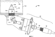
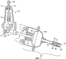
На фиг.1 на виде спереди представлен привод, управляемый изменением расхода, в комплекте с автоматическим запорным клапаном.Figure 1 in front view shows a drive controlled by a change in flow rate, complete with an automatic shut-off valve.
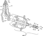
На фиг.2 привод по фиг.1 в комплекте с автоматическим запорным клапаном представлен в разрезе, причем клапан находится в запертом состоянии.In Fig. 2, the actuator of Fig. 1 complete with an automatic shut-off valve is shown in section, wherein the valve is in a locked state.
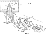
На фиг.3 привод по фиг.1 в комплекте с автоматическим запорным клапаном представлен в разрезе, после перемещения клапана приводом в состояние быстрого стравливания.In Fig. 3, the actuator of Fig. 1 complete with an automatic shut-off valve is presented in section, after the valve has been moved by the actuator to a state of rapid bleeding.
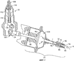
На фиг.4 привод по фиг.1 в комплекте с автоматическим запорным клапаном представлен в разрезе, после перемещения клапана приводом в открытое состояние.In Fig. 4, the actuator of Fig. 1 complete with an automatic shut-off valve is shown in section, after the valve is moved by the actuator to the open state.
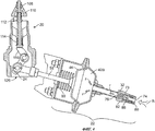
На фиг.5 привод по фиг.1 в комплекте с автоматическим запорным клапаном представлен в разрезе, причем рабочее положение клапана отвечает полностью открытому состоянию, а внутренний клапан избыточного расхода, входящий в конструкцию автоматического запорного клапана, заперт.In Fig. 5, the actuator of Fig. 1 complete with an automatic shut-off valve is shown in section, wherein the operating position of the valve corresponds to the fully open state, and the internal overflow valve included in the design of the automatic shut-off valve is locked.
На фиг.6 привод по фиг.1 в комплекте с автоматическим запорным клапаном представлен в разрезе после перемещения клапана приводом в полностью запертое состояние.In Fig. 6, the actuator of Fig. 1 complete with an automatic shut-off valve is shown in section after the valve has been moved by the actuator to a fully locked state.
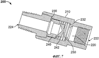
На фиг.7 представлен в разрезе другой пример клапана для управления текучей средой, пригодный для применения в приводе по фиг.1.FIG. 7 is a sectional view of another example of a fluid control valve suitable for use in the actuator of FIG. 1.
Осуществление изобретенияThe implementation of the invention
Приведенное далее описание не следует рассматривать как ограничивающее объем изобретения подробно рассмотренными в нем конкретными вариантами. Напротив, оно является только иллюстрацией принципов изобретения, обеспечивающей другим пользователям возможность использовать его положения.The following description should not be construed as limiting the scope of the invention to the specific embodiments detailed therein. On the contrary, it is only an illustration of the principles of the invention, providing other users the opportunity to use its provisions.
На прилагаемых чертежах и, конкретно на фиг.1 и 2, в качестве примера представлен дистанционно управляемый блок 10 балансировки давления пара. Блок 10 в общем случае содержит автоматический запорный клапан, например внутренний клапан 20, с которым функционально связано приводное устройство 22 с регулируемым расходом. В данном примере для обеспечения переходов клапана 20, по меньшей мере, между первым и вторым рабочими состояниями приводное устройство 22 подключено к рычагу 24 управления указанным клапаном. Проиллюстрированное приводное устройство 22 содержит гидрогазодинамический (например, пневматический) привод 30 и гидрогазодинамический управляющий клапан, такой, например, как ограничительный избыточный клапан 32, функционально связанный с впускным портом 34 привода 30, чтобы обеспечить управление расходом текучей среды в приводе 30.In the accompanying drawings, and specifically in FIGS. 1 and 2, a remotely controlled vapor
В данном примере клапан 20 представляет собой внутренний клапан, такой как внутренний клапан серии С407-10, производимой заявителем настоящего изобретения. Однако должно быть понятно, что в качестве клапана 20 может быть использовано активируемое устройство любого пригодного типа, в том числе и устройства, не являющиеся клапанами. Данный клапан 20 имеет корпус 100, содержащий верхнюю часть 102 и нижнюю часть 104, разделенные резьбовым участком 106. Участок 106 можно посредством резьбы соединить с ответным резьбовым отверстием 120 емкости 122 или какой-то другой емкости, пригодной для содержания текучей среды. В результате верхняя часть 102 клапана 20 оказывается введенной во внутренний объем емкости 122. В емкости 122 может содержаться под давлением текучая среда (т.е. газ или жидкость) 124, подлежащая доставке по назначению с истечением через выход 126 клапана 20. Для облегчения прохождения потока текучей среды из емкости 122 клапан 20 содержит выравнивающий (корректирующий) компонент 108, главную тарелку 110, пружину 112 избыточного расхода и закрывающую пружину 114, которая разжимается и сжимается, позволяя текучей среде проходить через клапан 20 с меняющимися расходами (скоростями) потока. Клапан 20 имеет, по меньшей мере, первое рабочее состояние и второе рабочее состояние, в которых он соответственно заперт и открыт. В данном примере у клапана 20 имеется также третье рабочее состояние (состояние быстрого стравливания), находящееся примерно посередине между первым и вторым рабочими состояниями. Рабочее состояние клапана 20 можно выбрать смещая рычаг 24 управления и тем самым поворачивая кулачок, как это будет описано далее. В дополнение к сказанному, приведение выравнивающего компонента 108 и главной тарелки 110 в открывающее и запирающее положения может произойти за счет перепадов давления на клапане 20, как это будет описано далее.In this example,
Как уже отмечалось, перемещение рычага 24 управления можно осуществить соединив его с приводным устройством 22. Например, указанное перемещение можно провести за счет функционального сопряжения рычага 24 управления с выходным элементом приводного устройства 22 (например, с его приводным штоком) таким образом, чтобы перемещение выходного элемента трансформировалось в перемещение рычага 24 управления. В проиллюстрированном примере гидрогазодинамический привод 30 приводного устройства 22 с регулируемым расходом выполнен на основе тормозной камеры 42, образованной корпусом 40. Указанная камера 42 разделена на первую камеру 42а и вторую камеру 42b гибкой диафрагмой 44, несущей на себе уплотняющую манжету 46 штока и накладку 48. Гибкая диафрагма 44 выполнена с возможностью смещения внутри камеры 42, например, посредством смещающего элемента, такого как пружина 50, установленная между стенкой камеры 42 и накладкой 48 диафрагмы. Уплотняющая манжета 46 поддерживает непроницаемое для текучей среды сопряжение приводного штока 52 с диафрагмой 44 и, по существу, ориентирует шток вдоль продольной оси 54 корпуса 40. Указанный приводной шток 52 продлен за пределы корпуса 40 с возможностью выполнять функцию выходного элемента и связан с рычагом 24 управления. В альтернативном варианте приводной шток 52 можно функционально соединить с любым количеством механических передач и/или устройств для проведения разнообразных востребованных операций.As already noted, the movement of the
Корпус 40 образует, по меньшей мере, один порт (например, впускной порт 34), связанный по потоку с первой камерой 42а, и, по меньшей мере, один порт 62, связанный по потоку со второй камерой 42b. В данном примере открытый конец впускного порта 34 функционально связан с ограничительным избыточным клапаном 32, например, через трубку 64 подачи текучей среды. В свою очередь, ограничительный избыточный клапан 32 функционально связан с наружным источником 65 подачи текучей среды, таким, например, как насос высокого давления. Текучей средой, подаваемой от наружного источника 65, может быть, в частности, нефть, вода, воздух и/или любая другая пригодная текучая среда.The
Ограничительный избыточный клапан 32 приводного устройства 22 может представлять собой односторонний расходный клапан, обладающий ограниченной способностью к стравливанию давления. Конкретно, клапан 32 содержит корпус 70, который задает сквозной канал 72, проходящий через него вдоль продольной оси 71 и имеющий входной порт 74 и выходной порт 76. В данном примере продольная ось 71 клапана 32 и продольная ось 54 привода 30 совпадают. Входной порт 74 выполнен с возможностью сопряжения с источником 65 рабочей текучей среды привода, а выходной порт 76 выполнен с возможностью сопряжения с приводом 30 через трубку 64 подачи текучей среды. Должно быть понятно, что хотя в данном случае ограничительный избыточный клапан 32, привод 30 и трубка 64 подачи текучей среды проиллюстрированы как отдельные компоненты, два из них или все три при желании можно интегрировать в единый компонент.The restrictive
В данном примере ограничительный избыточный клапан 32 сконструирован с возможностью управления расходом текучей среды, проходящей через сквозной канал 72 в направлении от входного порта 74 к выходному порту 76, но позволяет потоку проходить, по существу, неконтролируемым образом в направлении от выходного порта 76 к входному порту 74.In this example, the restrictive
Для осуществления управления текучей средой ограничительный избыточный клапан 32 содержит участок, образующий заплечик 73, т.е. имеющий уменьшенный диаметр, а также седло 80 и стравливающий диск 82, установленный в сквозном канале 72. Конкретно, в сквозном канале 72 седло 80 расположено проксимально по отношению к входному порту 74, а стравливающий диск 82 расположен между заплечиком 73 и седлом 80 стравливающего узла. В данном примере стравливающий диск 82 выполнен с возможностью перемещения в сквозном канале 72 между заплечиком 73 и седлом 80. В сторону седла 80 стравливающий диск 82 отжимается смещающим элементом, таким, например, как пружина 84.To control the fluid, the restrictive
В седле 80 выполнено несколько отверстий, таких, например, как первое и второе отверстия 80а, 80b, проходящие через седло 80 соответственно коаксиально и перпендикулярно продольной оси 71 сквозного канала 72. Стравливающий диск 82 имеет сквозное отверстие 82а, проходящее через стравливающий диск 82, по существу, коаксиальное продольной оси 71 сквозного канала 72. В данном примере на одном участке отверстия 82а диаметр уменьшен с образованием дросселирующего отверстия 86 для контроля и/или понижения расхода текучей среды, проходящей через отверстие 82а.Several holes are made in the
На фиг.2-6 блок 10 представлен в режиме нормального функционирования. На фиг.2 внутренний клапан 20 показан в своем первом рабочем состоянии, а именно в запертом состоянии, в котором герметичное перекрытие обеспечивается за счет совместного воздействия давления в емкости и закрывающей пружины 114 клапана 20. Указанное воздействие заключается в том, что давление в емкости и закрывающая пружина 114 смещают выравнивающий компонент 108 и главную тарелку 110 в сторону верхней части 102 клапана 20, предотвращая тем самым прохождение потока через клапан 20.Figure 2-6, block 10 is presented in normal operation. In figure 2, the
Фиг.3 иллюстрирует приводное устройство 22 с регулируемым расходом, к которому приложено давление таким образом, чтобы переместить рычаг 24 управления клапаном 20 в промежуточное рабочее положение, а именно в положение быстрого стравливания, которое позволяет уравновесить давление в емкости и на выходе 126. Более конкретно, в данном случае текучая среда подается под давлением во входной порт 74 от наружного источника с первым расходом R потока. Указанная среда входит в ограничительный избыточный клапан 32 через входной порт 74 и отжимает стравливающий диск 82 в сторону заплечика 73, тем самым вынуждая текучую среду проходить через дросселирующее отверстие 86. При этом расход текучей среды за дросселирующим отверстием 86, у выходного порта 76 уменьшается до уровня второго расхода r. В данном случае второй расход r меньше первого расхода R, причем его можно регулировать или изменять, добавляя другие отверстия, уменьшающие расход потока, изменяя смещающее усилие пружины 84 и/или варьируя размер дросселирующего отверстия 86. Далее текучая среда через выходной порт 76 выходит из ограничительного избыточного клапана 32 и попадает в камеру 42а, создавая в ней повышенное давление, воздействующее на диафрагму 44. Как только усилие, вызванное указанным давлением, станет достаточным для преодоления смещающего усилия пружины 50, а также усилия пружины 114 и усилия, создаваемого любым давлением на верхнюю часть клапана 20, диафрагма 44 и прикрепленный к ней приводной шток 52 переместятся по направлению к положению, показанному на фиг.3. Смещение рычага 24 управления клапаном приблизительно в среднее положение позволяет кулачку 116 передвинуть выравнивающий компонент 108 в открывающее положение. В результате по сравнению с ситуацией, когда рычаг 24 сразу же устанавливается в полностью открывающее положение (см. фиг.4), большее количество текучей среды 124, находящейся в емкости 122, имеет возможность пройти через выход 126.Figure 3 illustrates a variable
Фиг.4 иллюстрирует приводное устройство 22 с регулируемым расходом, к которому приложено давление таким образом, чтобы переместить рычаг 24 управления клапаном 20 во второе рабочее положение, а именно в полностью открывающее положение, позволяющее текучей среде 124, находящейся в емкости 122, вытекать через выход 126. Более конкретно, в данном случае текучая среда, находящаяся под давлением, продолжает поступать во входной порт 74 от наружного источника с первым расходом R. Указанная среда продолжает поступать в ограничительный избыточный клапан 32 через входной порт 74 и проходить через дросселирующее отверстие 86 с соответствующим уменьшением расхода потока у выходного порта 76 до второго значения r расхода. При этом давление в камере 42а продолжает повышаться, заставляя рычаг 24 управления переместиться по направлению к положению полного открывания. В этом положении, когда давление в емкости 122 и давление у выхода 126 уравновешены, пружина 112 избыточного расхода отжимает главную тарелку 110, открывая проход, и внутренний клапан 20 готов к режиму выпуска текучей среды.FIG. 4 illustrates a variable
Фиг.5 иллюстрирует приводное устройство 22 с регулируемым расходом, на которое подано максимальное давление. При этом рычаг 24 управления клапаном 20 остается в полностью открывающем положении. В данном случае давление внутри привода 30 и ограничительного избыточного клапана 32 примерно одинаково, в результате чего рычаг 24 управления удерживается в положении полного включения. В такой позиции воздействие потока (волны) текучей среды 124 через клапан 20 превышает усилие, прикладываемое пружиной 112 избыточного расхода, т.е. главная тарелка 110 оказывается в запирающем положении, показанном на чертеже. В этом случае небольшое количество текучей среды 124 будет продолжать стравливаться по течению потока через выравнивающий компонент 108. Кроме того, для описанной ситуации часто желательно вернуть клапан 20 в его запертое состояние, показанное на фиг.2 и 6, чтобы проанализировать и/или перезапустить условия выпуска текучей среды.5 illustrates a variable
Фиг.6 иллюстрирует приводное устройство 22 с регулируемым расходом после быстрого сброса давления, в результате чего клапан 20 возвращается в полностью запертое состояние. В данном случае источник текучей среды, находящейся под давлением, активным образом (например, через насос) и/или пассивно (например, путем смещающего воздействия) отсоединяется от приводного устройства 22 с регулируемым расходом, позволяя пружине 50 вернуть диафрагму 44 в ее смещенное положение. Конкретно, под воздействием усилия, приложенного пружиной 50, текучая среда, находящаяся в камере 42а, возвращается через выходной порт 76 ограничительного избыточного клапана 32 с расходом R' потока, позволяющим превысить усилие, прикладываемое пружиной 84. В результате стравливающий диск 82 отжимается в сторону седла 80 стравливающего узла. Сразу же после указанного перемещения стравливающего диска 82 текучая среда получает возможность проходить вокруг него наружу через входной порт 74 с относительно высоким расходом R" потока в обход дросселирующего отверстия 86 стравливающего диска 82. Это позволяет быстро переместить приводной шток 52, возвращая тем самым рычаг 24 управления в полностью запирающее положение.6 illustrates a
На фиг.7 представлен другой пример клапана для управления текучей средой, пригодный для применения в комплекте с ограничительным избыточным клапаном 32 и/или вместо него. Конкретно, фиг.7 иллюстрирует клапан 200 избыточного расхода, содержащий корпус 210 со сквозным каналом 220, соединяющим входной порт 224 и выходной порт 222. Входной порт выполнен с возможностью сопряжения с источником 65 рабочей текучей среды привода, а выходной порт выполнен с возможностью сопряжения с приводом 30 через трубку 64 подачи текучей среды. Хотя в данном случае клапан 200 избыточного расхода, привод 30 и трубка 64 подачи текучей среды проиллюстрированы в виде отдельных компонентов, два из них и/или все при желании также можно изготовить в виде единого компонента.7 illustrates another example of a fluid control valve suitable for use with and / or in place of the restrictive
Клапан 200 избыточного расхода содержит первый участок, образующий заплечик 230, т.е. имеющий уменьшенный диаметр, а также второй заплечик 232 и подвижный упор 240, установленный в сквозном канале 220 между заплечиками 230 и 232 с возможностью перемещения между ними в ответ на перепады давления между входным портом 224 и выходным портом 222. Таким образом, посредством смещающего элемента, например, такого как пружина 242, подвижный упор 240 при желании можно смещать как в сторону заплечика 230, так и в сторону заплечика 232. Через подвижный упор 240 проходит сквозное отверстие 250. Как и в случае ограничительного избыточного клапана 32, в процессе работы подвижный упор 240 может смещаться в сторону заплечика 232 при перемещении рычага 24 управления из запирающего положения в открывающее. Тем самым уменьшается расход потока текучей среды, поступающего в привод 30 через ограничивающее (дросселирующее) стравливающее отверстие или ограничивающий (дросселирующий) стравливающий зазор (не показаны) между заплечиком 232 и подвижным упором 240. При этом ограниченный поток проходит через клапан 200 избыточного расхода, обеспечивая замедление перехода привода из запирающего положения в открывающее. Аналогичным образом, во время возвращения рычага 24 управления из открывающего положения в запирающее предусмотрена возможность сместить подвижный упор 240 в сторону заплечика 230. Тем самым создаются условия для того, чтобы из привода 30 выходил, по существу, неконтролируемый поток текучей среды.The
Приводное устройство 22 было описано как сопряженное с клапаном 20, однако специалистам в этой области должно быть понятно, что его можно использовать в комплекте с любыми устройствами, для которых требуется обеспечить режим с регулируемым расходом. Кроме того, хотя для приводного устройства 22 был представлен вариант с регулируемым расходом на входе и фактически неуправляемым расходом на выходе, должно быть понятно, что при желании расходы можно регулировать или не регулировать как в каком-то одном из указанных направлений (вход или выход), так и в обоих направлениях.
Хотя положения изобретения были проиллюстрированы на примере конкретных вариантов осуществления, объем изобретения не ограничен приведенными вариантами. Напротив, данное изобретение охватывает все модификации и варианты осуществления, соответствующие прилагаемой формуле изобретения, причем как буквально, так и с учетом эквивалентов.Although the provisions of the invention have been illustrated by the example of specific embodiments, the scope of the invention is not limited to the above options. On the contrary, this invention covers all modifications and embodiments corresponding to the attached claims, both literally and taking into account equivalents.
Claims (19)
гидрогазодинамический привод, который содержит корпус, имеющий внутреннюю камеру и вход для текучей среды, связанный по потоку с внутренней камерой,
приводной шток, выступающий из корпуса, причем приводной шток установлен с возможностью перемещения в ответ на добавление текучей среды во внутреннюю камеру или удаление текучей среды из внутренней камеры, и
клапан управления текучей средой, связанный по потоку с указанным входом корпуса, причем клапан содержит:
корпус, который задает сквозной канал вдоль продольной оси, заплечик, установленный в сквозном канале,
седло, установленное в сквозном канале,
стравливающий диск, расположенный в сквозном канале между заплечиком и седлом, и
отверстие, проходящее через стравливающий диск,
при этом стравливающий диск выполнен с возможностью перемещения в сквозном канале между заплечиком и седлом в ответ на прохождение текучей среды через сквозной канал и с возможностью ограничивать расход потока текучей среды, проходящего через сквозной канал во внутреннюю камеру корпуса, и выпускать без ограничений поток текучей среды из внутренней камеры корпуса через сквозной канал.1. An adjustable flow actuator for a valve, comprising:
a hydro-gas-dynamic drive, which contains a housing having an inner chamber and an inlet for a fluid connected in a stream with the inner chamber,
a drive rod protruding from the housing, and the drive rod is mounted to move in response to the addition of fluid to the inner chamber or removal of fluid from the inner chamber, and
a fluid control valve in fluid communication with said inlet of the housing, the valve comprising
a housing that defines a through channel along a longitudinal axis, a shoulder mounted in a through channel,
saddle mounted in the through channel
a bleed disk located in the through channel between the shoulder and the saddle, and
the hole passing through the bleed disk,
while the bleeding disk is arranged to move in the through channel between the shoulder and the seat in response to the passage of fluid through the through channel and with the ability to limit the flow rate of the fluid passing through the through channel into the inner chamber of the housing, and to let out without limitation the flow of fluid from the inner chamber of the housing through the through channel.
автоматический запорный клапан, имеющий первое рабочее состояние и второе рабочее состояние, и
привод с регулируемым расходом, выполненный с возможностью обеспечения переходов автоматического запорного клапана между первым рабочим состоянием и вторым рабочим состоянием, при этом указанный привод содержит:
гидрогазодинамический привод, который содержит корпус, имеющий внутреннюю камеру и вход для текучей среды, связанный по потоку с внутренней камерой, и
приводной шток, выступающий из корпуса и функционально связанный с автоматическим запорным клапаном, причем приводной шток установлен с возможностью перемещения в ответ на добавление текучей среды во внутреннюю камеру или удаление текучей среды из внутренней камеры, и клапан управления текучей средой, связанный по потоку с указанным входом корпуса, причем клапан управления текучей средой содержит второй корпус, который задает сквозной канал вдоль продольной оси, заплечик, установленный в сквозном канале, седло, установленное в сквозном канале, стравливающий диск, расположенный в сквозном канале между заплечиком и указанным седлом, который содержит проходящее через него отверстие, при этом стравливающий диск выполнен с возможностью перемещения в сквозном канале между заплечиком и седлом в ответ на прохождение текучей среды через сквозной канал и с возможностью регулировать расход потока текучей среды, проходящего через клапан управления текучей средой во внутреннюю камеру корпуса, и выпускать без ограничений поток текучей среды из внутренней камеры корпуса через клапан управления текучей средой.10. A fluid control device comprising:
an automatic shut-off valve having a first operational state and a second operational state, and
a variable flow drive configured to provide automatic shutoff valve transitions between a first operational state and a second operational state, wherein said actuator comprises:
a hydro-gas-dynamic drive, which contains a housing having an inner chamber and an inlet for a fluid connected in flow to the inner chamber, and
a drive rod protruding from the housing and operably associated with an automatic shutoff valve, the drive rod being mounted to move in response to adding fluid to the inner chamber or removing fluid from the inner chamber, and a fluid control valve in fluid communication with said inlet housing, and the fluid control valve comprises a second housing that defines a through channel along the longitudinal axis, a shoulder mounted in the through channel, a saddle mounted in the through m channel, a bleed disk located in the through channel between the shoulder and the specified saddle, which contains a hole passing through it, while the bleeding disk is arranged to move in the through channel between the shoulder and the saddle in response to the passage of fluid through the through channel and with the possibility to regulate the flow rate of the fluid flow passing through the fluid control valve into the inner chamber of the housing, and to let out without limitation the fluid flow from the inner chamber of the housing through apan fluid control.
Applications Claiming Priority (3)
| Application Number | Priority Date | Filing Date | Title |
|---|---|---|---|
| US11/764,012 US8262057B2 (en) | 2007-06-15 | 2007-06-15 | Flow controlled actuator apparatus for use with self-closing stop valves |
| US11/764,012 | 2007-06-15 | ||
| PCT/US2008/065396 WO2008156998A1 (en) | 2007-06-15 | 2008-05-30 | Flow controlled actuator apparatus for use with self-closing stop valves |
Publications (2)
| Publication Number | Publication Date |
|---|---|
| RU2009147170A RU2009147170A (en) | 2011-07-20 |
| RU2479776C2 true RU2479776C2 (en) | 2013-04-20 |
Family
ID=39735022
Family Applications (1)
| Application Number | Title | Priority Date | Filing Date |
|---|---|---|---|
| RU2009147170/06A RU2479776C2 (en) | 2007-06-15 | 2008-05-30 | Driving device with controlled flow rate for use with automatic shut-off valves |
Country Status (9)
| Country | Link |
|---|---|
| US (1) | US8262057B2 (en) |
| EP (1) | EP2165099B1 (en) |
| JP (2) | JP2010530500A (en) |
| CN (1) | CN101680563B (en) |
| AR (1) | AR067015A1 (en) |
| BR (1) | BRPI0813365B1 (en) |
| CA (1) | CA2689197C (en) |
| RU (1) | RU2479776C2 (en) |
| WO (1) | WO2008156998A1 (en) |
Families Citing this family (9)
| Publication number | Priority date | Publication date | Assignee | Title |
|---|---|---|---|---|
| US8517046B2 (en) * | 2009-04-03 | 2013-08-27 | Emerson Process Management Regulator Technologies, Inc. | Redundant metal-to-metal seals for use with internal valves |
| US9360131B2 (en) * | 2010-04-09 | 2016-06-07 | Emerson Process Management Regulator Technologies, Inc. | Actuator adapter plate |
| US10295081B2 (en) | 2017-03-10 | 2019-05-21 | Emerson Process Management Regulator Technologies, Inc. | Valve body having primary and secondary stem guides |
| US10563786B2 (en) | 2017-03-10 | 2020-02-18 | Emerson Process Management Regulator Technologies, Inc. | Internal valve system with valve inlet positioned relative to container feed inlet |
| US10480682B2 (en) | 2017-03-10 | 2019-11-19 | Emerson Process Management Regulator Technologies, Inc. | Strainer assembly for internal valve |
| CN108571607B (en) * | 2017-03-10 | 2021-11-16 | 艾默生过程管理调节技术公司 | Internal valve system with valve inlet positioned relative to container feed inlet |
| US10641404B2 (en) | 2017-03-10 | 2020-05-05 | Emerson Process Management Regulator Technologies, Inc. | Spring seat for an internal valve |
| US10794505B2 (en) * | 2017-03-10 | 2020-10-06 | Emerson Process Management Regulator Technologies, Inc. | Spring seat for an internal valve |
| JP7128849B2 (en) | 2017-06-23 | 2022-08-31 | グラコ ミネソタ インコーポレーテッド | variable flow poppet valve |
Citations (6)
| Publication number | Priority date | Publication date | Assignee | Title |
|---|---|---|---|---|
| CH543024A (en) * | 1971-09-28 | 1973-10-15 | Far Fab Assortiments Reunies | Quick return choke |
| US3844312A (en) * | 1971-11-22 | 1974-10-29 | Fisher Controls Co | Rapid equalizing tight shut-off internal control valve |
| SU540096A1 (en) * | 1975-04-04 | 1976-12-25 | Предприятие П/Я А-7899 | Safety device |
| SU994843A1 (en) * | 1980-05-23 | 1983-02-07 | Предприятие П/Я В-2700 | Safety locking valve |
| SU1067281A1 (en) * | 1982-03-24 | 1984-01-15 | Проектно-Конструкторское Бюро Главного Управления Вагонного Хозяйства | Pressure stabilizer |
| SU1229498A1 (en) * | 1984-11-29 | 1986-05-07 | Ордена Трудового Красного Знамени Институт Тепло -И Массообмена Им.А.В.Лыкова | Safety device |
Family Cites Families (34)
| Publication number | Priority date | Publication date | Assignee | Title |
|---|---|---|---|---|
| US824425A (en) * | 1902-07-24 | 1906-06-26 | Charles H Johnson | Governor for fluid-pressure motors. |
| US2179144A (en) * | 1937-08-07 | 1939-11-07 | Bastian Blessing Co | Excess flow check valve |
| US2318962A (en) * | 1940-08-03 | 1943-05-11 | Arthur L Parker | Valve assembly |
| US2450446A (en) * | 1946-12-12 | 1948-10-05 | Earl V Rupp | Oxygen warning device |
| US2676613A (en) * | 1952-08-16 | 1954-04-27 | Baxter Benjamin | Dual purpose valve unit |
| US3164359A (en) * | 1960-10-10 | 1965-01-05 | Phillips Petroleum Co | Safety flow valve |
| JPS433451Y1 (en) * | 1964-10-05 | 1968-02-13 | ||
| US3872884A (en) * | 1972-11-20 | 1975-03-25 | Parker Hannifer Corp | Excess flow check valve |
| JPS49150937U (en) * | 1973-04-26 | 1974-12-27 | ||
| US4044791A (en) * | 1975-12-10 | 1977-08-30 | City Tank Corporation | Valve assembly |
| US4073311A (en) | 1976-12-10 | 1978-02-14 | Numatics, Incorporated | Flow control valve |
| US4174731A (en) * | 1977-11-21 | 1979-11-20 | The Hansen Manufacturing Company | Excess flow limiting valve |
| JPS55126110A (en) * | 1979-03-19 | 1980-09-29 | Dengensha Mfg Co Ltd | Press cylinder |
| JPS6014240U (en) * | 1983-07-08 | 1985-01-30 | トヨタ自動車株式会社 | Internal combustion engine intake control device |
| US4704947A (en) * | 1985-10-21 | 1987-11-10 | Versa Technologies, Inc. | Bidirectional fluid flow valve |
| US4741252A (en) * | 1986-09-24 | 1988-05-03 | Allied-Signal Inc. | Diaphragm of the rolling type having a membrane portion and a reinforcing portion |
| JPH081134B2 (en) * | 1987-05-21 | 1996-01-10 | 株式会社日立製作所 | Actuator for turbocharger flow path switching valve |
| US4896696A (en) * | 1989-07-03 | 1990-01-30 | Aeroquip Corporation | Flow control restrictor |
| JPH0754703Y2 (en) * | 1989-08-30 | 1995-12-18 | 株式会社小松製作所 | Check valve |
| JPH0450777U (en) * | 1990-09-06 | 1992-04-28 | ||
| WO1992008898A1 (en) * | 1990-11-08 | 1992-05-29 | Allied-Signal Inc. | Dual area brake actuation piston mechanism |
| US5215113A (en) * | 1991-06-20 | 1993-06-01 | Terry Paul E | Precision safety shut-off valve |
| SE503140C2 (en) * | 1992-05-07 | 1996-04-01 | Dart Engineering Ag | Device at media transmitting unit |
| JP2548365Y2 (en) * | 1992-05-21 | 1997-09-17 | 株式会社トキメック | Hydraulic cylinder |
| US5474105A (en) * | 1994-03-31 | 1995-12-12 | The Aro Corporation | Overrun control device |
| US5462081A (en) * | 1994-08-24 | 1995-10-31 | Nupro Company | Excess flow valve |
| US5465751A (en) * | 1994-12-14 | 1995-11-14 | R.W. Lyall & Company, Inc. | Excess flow valve |
| JPH11132342A (en) * | 1997-10-30 | 1999-05-21 | Koyo Seiko Co Ltd | Check valve |
| JP3734644B2 (en) * | 1999-06-23 | 2006-01-11 | 日野自動車株式会社 | Overflow prevention valve return device |
| AT408480B (en) | 1999-12-07 | 2001-12-27 | Hoerbiger Hydraulik | THROTTLE CHECK VALVE AND METHOD FOR THE PRODUCTION THEREOF |
| US6546839B1 (en) * | 2000-08-22 | 2003-04-15 | Titantechnologies International, Inc. | Flow regulation device |
| US6920895B2 (en) * | 2001-04-16 | 2005-07-26 | Alan Avis | Combination surge supression and safety shut-off valve |
| US7293579B2 (en) * | 2004-07-08 | 2007-11-13 | Caterpillar Inc. | Poppet valve arrangements |
| US7455279B2 (en) * | 2005-06-23 | 2008-11-25 | Bermad Cs, Ltd | Hydraulic control valve with integrated dual actuators |
-
2007
- 2007-06-15 US US11/764,012 patent/US8262057B2/en active Active
-
2008
- 2008-05-30 RU RU2009147170/06A patent/RU2479776C2/en active
- 2008-05-30 EP EP08756562.8A patent/EP2165099B1/en active Active
- 2008-05-30 BR BRPI0813365-4A patent/BRPI0813365B1/en not_active IP Right Cessation
- 2008-05-30 JP JP2010512255A patent/JP2010530500A/en active Pending
- 2008-05-30 WO PCT/US2008/065396 patent/WO2008156998A1/en active Application Filing
- 2008-05-30 CN CN2008800203403A patent/CN101680563B/en active Active
- 2008-05-30 CA CA 2689197 patent/CA2689197C/en active Active
- 2008-06-13 AR ARP080102551 patent/AR067015A1/en active IP Right Grant
-
2013
- 2013-01-21 JP JP2013008669A patent/JP5718381B2/en active Active
Patent Citations (6)
| Publication number | Priority date | Publication date | Assignee | Title |
|---|---|---|---|---|
| CH543024A (en) * | 1971-09-28 | 1973-10-15 | Far Fab Assortiments Reunies | Quick return choke |
| US3844312A (en) * | 1971-11-22 | 1974-10-29 | Fisher Controls Co | Rapid equalizing tight shut-off internal control valve |
| SU540096A1 (en) * | 1975-04-04 | 1976-12-25 | Предприятие П/Я А-7899 | Safety device |
| SU994843A1 (en) * | 1980-05-23 | 1983-02-07 | Предприятие П/Я В-2700 | Safety locking valve |
| SU1067281A1 (en) * | 1982-03-24 | 1984-01-15 | Проектно-Конструкторское Бюро Главного Управления Вагонного Хозяйства | Pressure stabilizer |
| SU1229498A1 (en) * | 1984-11-29 | 1986-05-07 | Ордена Трудового Красного Знамени Институт Тепло -И Массообмена Им.А.В.Лыкова | Safety device |
Also Published As
| Publication number | Publication date |
|---|---|
| US20080308161A1 (en) | 2008-12-18 |
| CA2689197A1 (en) | 2008-12-24 |
| EP2165099B1 (en) | 2015-11-11 |
| CN101680563B (en) | 2013-05-15 |
| JP2010530500A (en) | 2010-09-09 |
| WO2008156998A1 (en) | 2008-12-24 |
| BRPI0813365A2 (en) | 2014-12-30 |
| CN101680563A (en) | 2010-03-24 |
| US8262057B2 (en) | 2012-09-11 |
| JP5718381B2 (en) | 2015-05-13 |
| BRPI0813365B1 (en) | 2020-03-10 |
| RU2009147170A (en) | 2011-07-20 |
| JP2013127317A (en) | 2013-06-27 |
| CA2689197C (en) | 2014-07-08 |
| EP2165099A1 (en) | 2010-03-24 |
| AR067015A1 (en) | 2009-09-30 |
Similar Documents
| Publication | Publication Date | Title |
|---|---|---|
| RU2479776C2 (en) | Driving device with controlled flow rate for use with automatic shut-off valves | |
| US7565793B2 (en) | Gas turbine engine fuel control system having start / back up check valve (SBUC) providing a main fuel check valve function | |
| CN1862031B (en) | Anti jerk valve | |
| CN102177378B (en) | Valves having removable internal actuation mechanisms | |
| AU2009295049B2 (en) | Fluid regulator | |
| RU2643428C2 (en) | Regulator of refrigeration with light start of the pump | |
| CN101514762B (en) | An improved by-pass and pressure regulator valve | |
| RU2558487C2 (en) | Device increasing force of drive with locking device | |
| CN103597219A (en) | Hydraulic actuating assembly | |
| WO1998015762A1 (en) | Automatic regulating valve apparatus | |
| WO2013111503A1 (en) | Actuator | |
| US9933085B2 (en) | Integrating valve with soft start | |
| US7735618B2 (en) | Clutch control device | |
| JP2005048796A (en) | Automatic regulating valve apparatus | |
| US8286662B2 (en) | Switching valve with slider | |
| US20190168039A1 (en) | Air-pressure controlled piston and valve configuration | |
| US20130306887A1 (en) | Valve arrangement | |
| US11021237B2 (en) | Aircraft hydraulic system | |
| WO1995013573A1 (en) | Proportioning valve | |
| KR20190063857A (en) | Hydraulic control system of automatic transmission for vehicles | |
| RU2217639C2 (en) | Valve-type selector | |
| JPH07317933A (en) | Spool type exhaust preventive valve | |
| JP2002031300A (en) | Decompression device |