RU2479012C2 - Three-dimensional shadow mouse pointer - Google Patents
Three-dimensional shadow mouse pointer Download PDFInfo
- Publication number
- RU2479012C2 RU2479012C2 RU2009116262/08A RU2009116262A RU2479012C2 RU 2479012 C2 RU2479012 C2 RU 2479012C2 RU 2009116262/08 A RU2009116262/08 A RU 2009116262/08A RU 2009116262 A RU2009116262 A RU 2009116262A RU 2479012 C2 RU2479012 C2 RU 2479012C2
- Authority
- RU
- Russia
- Prior art keywords
- dimensional
- location
- locations
- pointer
- projection
- Prior art date
Links
Images
Classifications
-
- G—PHYSICS
- G06—COMPUTING; CALCULATING OR COUNTING
- G06F—ELECTRIC DIGITAL DATA PROCESSING
- G06F3/00—Input arrangements for transferring data to be processed into a form capable of being handled by the computer; Output arrangements for transferring data from processing unit to output unit, e.g. interface arrangements
- G06F3/01—Input arrangements or combined input and output arrangements for interaction between user and computer
- G06F3/048—Interaction techniques based on graphical user interfaces [GUI]
- G06F3/0481—Interaction techniques based on graphical user interfaces [GUI] based on specific properties of the displayed interaction object or a metaphor-based environment, e.g. interaction with desktop elements like windows or icons, or assisted by a cursor's changing behaviour or appearance
- G06F3/04815—Interaction with a metaphor-based environment or interaction object displayed as three-dimensional, e.g. changing the user viewpoint with respect to the environment or object
Abstract
Description
Область техникиTechnical field
Настоящее изобретение относится к области человеко-машинного взаимодействия и более конкретно к визуализации указателя в проекции трехмерной области.The present invention relates to the field of human-machine interaction, and more particularly to visualization of a pointer in a projection of a three-dimensional region.
Уровень техникиState of the art
В некоторых приложениях, таких как маркировка повреждений, сегментация и выполнение измерений, пользователю необходимо указывать трехмерное (3D) местоположение на интересующей структуре, показанной на проекции трехмерной области. Часто существует множество структур на проекции, так что передвижение указателя по направлению к местоположению на интересующей структуре может быть затруднительным. В некоторых приложениях визуализация указателя на проекции трехмерной области улучшается с помощью наложения тени, также называемой отпечатком, на видимую структуру на проекции трехмерной области. Тень обеспечивает пользователю обратную связь по местоположению указателя. Проблема, связанная с таким подходом, заключается в том, что тень может указывать как интересующую структуру, так и структуру на заднем плане, когда тень слишком большая, или в том, что тень почти не видна, когда тень слишком маленькая.In some applications, such as damage marking, segmentation and measurement, the user needs to indicate a three-dimensional (3D) location on the structure of interest, shown on the projection of the three-dimensional region. Often there are many structures on the projection, so moving the pointer towards a location on the structure of interest can be difficult. In some applications, the visualization of the pointer on the projection of the three-dimensional region is improved by applying a shadow, also called a fingerprint, to the visible structure on the projection of the three-dimensional region. The shadow provides the user with feedback on the location of the pointer. The problem with this approach is that the shadow can indicate both the structure of interest and the structure in the background when the shadow is too large, or that the shadow is almost invisible when the shadow is too small.
Сущность изобретенияSUMMARY OF THE INVENTION
На проекции, содержащей множество структур различных размеров, невозможно определить один универсальный размер тени, соответствующий размерам всех структур. Кроме того, для анизотропной, например, удлиненной структуры тень также должна быть анизотропной, например удлиненной и ориентированной для того, чтобы соответствовать ориентации структуры.On a projection containing many structures of various sizes, it is impossible to determine one universal size of the shadow corresponding to the sizes of all structures. In addition, for an anisotropic, for example, elongated structure, the shadow must also be anisotropic, for example elongated and oriented in order to correspond to the orientation of the structure.
Было бы полезно иметь систему, способную определять обратную связь, которая повышает четкость и снижает неопределенность указания трехмерного местоположения на интересующей структуре.It would be useful to have a system capable of detecting feedback that improves clarity and reduces the uncertainty of indicating a three-dimensional location on the structure of interest.
Для того чтобы лучше решить эту задачу, в одном аспекте настоящего изобретения система определения обратной связи по трехмерному местоположению указателя в трехмерной области данных изображения содержит:In order to better solve this problem, in one aspect of the present invention, a system for determining feedback from a three-dimensional location of a pointer in a three-dimensional region of image data comprises:
блок отображения для вычисления проекции трехмерной области для отображения на устройстве отображения;a display unit for calculating a projection of a three-dimensional region for display on a display device;
блок указателя для вычисления двухмерного местоположения указателя на проекции трехмерной области на основе входного сигнала местоположения указателя;a pointer unit for calculating a two-dimensional location of the pointer on the projection of the three-dimensional region based on the input signal of the location of the pointer;
блок местоположения для вычисления трехмерного местоположения в трехмерной области на основе двухмерного местоположения на проекции трехмерной области; иa location unit for calculating a three-dimensional location in the three-dimensional region based on the two-dimensional location on the projection of the three-dimensional region; and
блок тени для определения множества двухмерных местоположений для отображения тени на проекции трехмерной области, причем множество двухмерных местоположений для отображения тени содержит двухмерное местоположение указателя на проекции трехмерной области и множество трехмерных местоположений, вычисленное на основе множества двухмерных местоположений для отображения тени, является связанным, таким образом определяя обратную связь по трехмерному местоположению указателя в трехмерной области данных изображения.a shadow unit for determining a plurality of two-dimensional locations for displaying a shadow on a projection of a three-dimensional region, wherein a plurality of two-dimensional locations for displaying a shadow comprises a two-dimensional location of a pointer on a projection of a three-dimensional region and a plurality of three-dimensional locations calculated based on a plurality of two-dimensional locations for displaying a shadow is thus connected determining feedback by the three-dimensional location of the pointer in the three-dimensional region of the image data.
Блок тени выполнен с возможностью генерации возможных двухмерных местоположений для отображения тени на проекции трехмерной области и использования блока местоположения для вычисления трехмерного местоположения возможных двухмерных местоположений, называемых далее возможными трехмерными местоположениями. Возможные двухмерные местоположения содержат двухмерное местоположение указателя. Трехмерное местоположение указателя, вычисленное на основе двухмерного местоположения указателя, также содержится во множестве возможных трехмерных местоположений. Блок тени, кроме того, выполнен с возможностью определения связанного множества возможных трехмерных местоположений, содержащего трехмерное местоположение указателя. Обычно связанное множество возможных трехмерных местоположений, содержащее трехмерное местоположение указателя, содержится в структуре, указанной с помощью указателя. Возможное двухмерное местоположение, такое что возможное трехмерное местоположение, вычисленное на основе упомянутого возможного двухмерного местоположения, содержится в упомянутом связанном множестве возможных трехмерных местоположений, принадлежит множеству двухмерных местоположений для отображения тени на проекции трехмерной области. Следовательно, система выполнена с возможностью подбирать размер и форму тени под размер и форму структуры, отображаемой на проекции трехмерной области, таким образом определяя обратную связь по трехмерному местоположению указателя на проекции трехмерной области данных изображения, что повышает четкость и снижает неопределенность указания трехмерного местоположения на структуре.The shadow block is configured to generate possible two-dimensional locations to display the shadow on the projection of the three-dimensional region and use the location block to calculate the three-dimensional location of the possible two-dimensional locations, hereinafter referred to as possible three-dimensional locations. Possible two-dimensional locations contain a two-dimensional pointer location. The three-dimensional location of the pointer, calculated based on the two-dimensional location of the pointer, is also contained in a variety of possible three-dimensional locations. The shadow block is also configured to determine an associated set of possible three-dimensional locations containing the three-dimensional location of the pointer. Usually a related set of possible three-dimensional locations containing a three-dimensional location of the pointer is contained in the structure indicated by the pointer. A possible two-dimensional location, such that a possible three-dimensional location, calculated on the basis of said possible two-dimensional location, is contained in the aforementioned associated set of possible three-dimensional locations, belongs to a plurality of two-dimensional locations for displaying a shadow on a projection of a three-dimensional region. Therefore, the system is configured to select the size and shape of the shadow according to the size and shape of the structure displayed on the projection of the three-dimensional region, thereby determining feedback by the three-dimensional location of the pointer on the projection of the three-dimensional region of the image data, which increases the clarity and reduces the uncertainty of indicating the three-dimensional location on the structure .
В одном варианте осуществления системы множество двухмерных местоположений для отображения тени является связанным. В принципе, если отбросить условие, что множество двухмерных местоположений для отображения тени является связанным, то тогда возможно, чтобы множество возможных двухмерных местоположений, которые отображаются на связанное множество возможных трехмерных местоположений, содержало множество компонентов связанности. Наличие упомянутого условия гарантирует, что множество двухмерных местоположений для отображения тени на проекции трехмерной области является связанным.In one embodiment of the system, a plurality of two-dimensional locations for displaying a shadow is related. In principle, if we discard the condition that the set of two-dimensional locations for displaying the shadow is connected, then it is possible that the set of possible two-dimensional locations that are mapped to the connected set of possible three-dimensional locations contains many connected components. The presence of said condition ensures that a plurality of two-dimensional locations for displaying a shadow on a projection of a three-dimensional region is connected.
В одном варианте осуществления системы множество двухмерных местоположений для отображения содержится в окружности с центром в двухмерном местоположении указателя на проекции трехмерной области. Длина диаметра окружности определяет максимальный размер тени. Возможные двухмерные местоположения могут быть с легкостью определены как местоположения внутри окружности.In one embodiment of the system, a plurality of two-dimensional locations for display are contained in a circle centered at the two-dimensional location of the pointer on the projection of the three-dimensional region. The circumference of the circle determines the maximum size of the shadow. Possible two-dimensional locations can be easily identified as locations within a circle.
В одном варианте осуществления системы блок местоположения выполнен с возможностью вычисления трехмерного местоположения в трехмерной области на основе двухмерного местоположения на проекции трехмерной области с использованием значения глубины двухмерного местоположения на проекции трехмерной области, сохраненной в буфере глубины. Использование буфера глубины обеспечивает быстрый способ вычисления трехмерного местоположения на основе двухмерного местоположения с помощью графического аппаратного обеспечения.In one embodiment of the system, the location unit is configured to calculate a three-dimensional location in the three-dimensional region based on the two-dimensional location on the projection of the three-dimensional region using the depth value of the two-dimensional location on the projection of the three-dimensional region stored in the depth buffer. Using a depth buffer provides a quick way to calculate a three-dimensional location based on a two-dimensional location using graphical hardware.
В одном варианте осуществления системы блок местоположения выполнен с возможностью вычисления трехмерного местоположения в трехмерной области на основе двухмерного местоположения на проекции трехмерной области с использованием отслеживания лучей. Использование отслеживания лучей обеспечивает более распространенный способ вычисления трехмерного местоположения на основе двухмерного местоположения, чем использование буфера глубины.In one embodiment of the system, the location unit is configured to calculate a three-dimensional location in the three-dimensional region based on the two-dimensional location on the projection of the three-dimensional region using ray tracking. Using ray tracking provides a more common way to calculate a three-dimensional location based on a two-dimensional location than using a depth buffer.
В одном варианте осуществления системы блок тени дополнительно выполнен с возможностью определения цвета тени для отображения тени на основе характеристики множества двухмерных местоположений или на основе характеристики множества трехмерных местоположений. Например, блок тени может быть дополнительно выполнен с возможностью вычисления трехмерного тензора моментов инерции множества трехмерных местоположений. Если отношение наибольшего главного значения к наименьшему главному значению больше, чем заданное пороговое значение, то можно считать, что тень указывает удлиненную структуру и может быть показана в первом цвете. В противном случае можно считать, что тень указывает овальную структуру и может быть показана во втором цвете.In one embodiment of the system, the shadow block is further configured to determine a shadow color for displaying the shadow based on a characteristic of a plurality of two-dimensional locations or based on a characteristic of a plurality of three-dimensional locations. For example, the shadow block may be further configured to calculate a three-dimensional tensor of inertia moments of a plurality of three-dimensional locations. If the ratio of the largest principal value to the smallest principal value is greater than a predetermined threshold value, then it can be considered that the shadow indicates an elongated structure and can be shown in the first color. Otherwise, we can assume that the shadow indicates an oval structure and can be shown in the second color.
В дополнительном аспекте изобретения система в соответствии с настоящим изобретением содержится в устройстве захвата изображения.In a further aspect of the invention, a system in accordance with the present invention is contained in an image capturing apparatus.
В дополнительном аспекте изобретения система в соответствии с настоящим изобретением содержится в рабочей станции.In an additional aspect of the invention, the system in accordance with the present invention is contained in a workstation.
В дополнительном аспекте изобретения способ определения обратной связи по трехмерному местоположению указателя в трехмерной области данных изображения содержит:In an additional aspect of the invention, a method for determining feedback from a three-dimensional location of a pointer in a three-dimensional region of image data comprises:
этап отображения для вычисления проекции трехмерной области для отображения на устройстве отображения;a display step for calculating a projection of a three-dimensional region for display on a display device;
этап указателя для вычисления двухмерного местоположения указателя на проекции трехмерной области на основе входного сигнала местоположения указателя;a pointer step for calculating a two-dimensional location of the pointer on a projection of the three-dimensional region based on the input signal of the location of the pointer;
этап местоположения для вычисления трехмерного местоположения в трехмерной области на основе двухмерного местоположения на проекции трехмерной области; иa location step for calculating a three-dimensional location in the three-dimensional region based on the two-dimensional location on the projection of the three-dimensional region; and
этап тени для определения множества двухмерных местоположений для отображения тени на проекции трехмерной области, причем множество двухмерных местоположений для отображения тени содержит двухмерные местоположения указателя на проекции трехмерной области и множество трехмерных местоположений, вычисленное на основе множества двухмерных местоположений для отображения тени, является связанным, таким образом определяя обратную связь по трехмерному местоположению указателя в трехмерной области данных изображения.a shadow step for determining a plurality of two-dimensional locations for displaying a shadow on a projection of a three-dimensional region, wherein a plurality of two-dimensional locations for displaying a shadow comprises two-dimensional locations of a pointer on a projection of a three-dimensional region and a plurality of three-dimensional locations calculated based on a plurality of two-dimensional locations for displaying a shadow is thus connected determining feedback by the three-dimensional location of the pointer in the three-dimensional region of the image data.
В дополнительном аспекте изобретения компьютерный программный продукт, предназначенный для загрузки компьютерным устройством, содержит инструкции для определения обратной связи по трехмерному местоположению указателя в трехмерной области данных изображения, причем компьютерное устройство содержит блок обработки и память, причем компьютерный программный продукт, после того как он загружен, позволяет упомянутому блоку обработки выполнять следующие задачи:In an additional aspect of the invention, a computer program product for downloading by a computer device comprises instructions for determining feedback on a three-dimensional location of a pointer in a three-dimensional region of image data, the computer device comprising a processing unit and a memory, the computer program product being downloaded, allows said processing unit to perform the following tasks:
вычисление проекции трехмерной области для отображения на устройстве отображения;calculating a projection of a three-dimensional region for display on a display device;
вычисление двухмерного местоположения указателя на проекции трехмерной области на основе входного сигнала местоположения указателя;calculating a two-dimensional location of the pointer on the projection of the three-dimensional region based on the input signal of the location of the pointer;
вычисление трехмерного местоположения в трехмерной области на основе двухмерного местоположения на проекции трехмерной области; иcalculating a three-dimensional location in a three-dimensional region based on a two-dimensional location on a projection of a three-dimensional region; and
определение множества двухмерных местоположений для отображения тени на проекции трехмерной области, причем множество двухмерных местоположений для отображения тени содержит двухмерное местоположение указателя на проекции трехмерной области и множество трехмерных местоположений, вычисленное на основе множества двухмерных местоположений для отображения тени, является связанным, таким образом определяя обратную связь по трехмерному местоположению указателя в трехмерной области данных изображения.determining a plurality of two-dimensional locations for displaying a shadow on a projection of a three-dimensional region, the plurality of two-dimensional locations for displaying a shadow comprising a two-dimensional location of a pointer on a projection of a three-dimensional region and a plurality of three-dimensional locations calculated based on a plurality of two-dimensional locations for displaying a shadow, is related, thereby determining feedback by the three-dimensional location of the pointer in the three-dimensional region of the image data.
Модификации и их разновидности устройства захвата изображения рабочей станции, способа и/или компьютерного программного продукта, который соответствует описываемым модификациям системы и их разновидностям, могут быть выполнены специалистами на основе настоящего описания.Modifications and their variations of the image capture device of the workstation, method and / or computer software product that corresponds to the described modifications of the system and their variants can be performed by specialists based on the present description.
Специалисту будет понятно, что способ можно применять для данных трехмерных и четырехмерных изображений, полученных с помощью различных модальностей захвата, например, но не ограничиваясь этим, компьютерной томографии (CT), отображения магнитного резонанса (MRI), ультразвука (US), томографии, основанной на методе позитронной эмиссии (PET), компьютерной томографии на основе эмиссии одного фотона (SPECT) и ядерной медицины (NM).One skilled in the art will understand that the method can be applied to three-dimensional and four-dimensional image data obtained using various capture modalities, for example, but not limited to, computed tomography (CT), magnetic resonance imaging (MRI), ultrasound (US), based tomography using the method of positron emission (PET), computed tomography based on the emission of one photon (SPECT) and nuclear medicine (NM).
Краткое описание чертежейBrief Description of the Drawings
Эти и другие аспекты изобретения станут очевидны и будут разъяснены в отношении вариантов осуществления и модификаций, описанных далее со ссылкой на прилагаемые чертежи, на которых:These and other aspects of the invention will become apparent and will be explained in relation to the embodiments and modifications described below with reference to the accompanying drawings, in which:
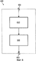
на фиг. 1 показана условно структурная схема примера варианта осуществления системы;in FIG. 1 is a schematic structural diagram of an example embodiment of a system;
на фиг. 2 показана проекция трехмерной области данных изображения, содержащая пример структуры и иллюстрирующая пример обратной связи по трехмерному местоположению указателя в трехмерной области;in FIG. 2 shows a projection of a three-dimensional region of image data containing an example of a structure and illustrating an example of feedback on a three-dimensional location of a pointer in a three-dimensional region;
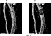
на фиг. 3 показаны две идентичные проекции трехмерной области данных изображения, содержащие кровеносный сосуд и зашумленную структуру и иллюстрирующие два примера обратных связей по трехмерным местоположениям указателя в трехмерной области;in FIG. 3 shows two identical projections of a three-dimensional region of image data containing a blood vessel and a noisy structure and illustrating two examples of feedbacks at three-dimensional locations of a pointer in a three-dimensional region;
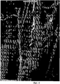
на фиг. 4 показана проекция трехмерной области данных изображения, содержащая тонкий кровеносный сосуд поверх занятого фона и иллюстрирующая пример обратной связи по трехмерному местоположению указателя в трехмерной области;in FIG. 4 shows a projection of a three-dimensional region of image data containing a thin blood vessel over a busy background and illustrating an example of feedback on a three-dimensional location of a pointer in a three-dimensional region;
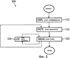
на фиг. 5 показана схема последовательности операций примера осуществления способа;in FIG. 5 is a flowchart of an example embodiment of the method;
на фиг. 6 показан условно пример варианта осуществления устройства захвата изображения; иin FIG. 6 shows a conditional example of an embodiment of an image capturing apparatus; and
на фиг. 7 показан условно пример варианта осуществления рабочей станции.in FIG. 7 shows a conditionally example embodiment of a workstation.
Одинаковые цифровые обозначения используются для обозначения аналогичных частей по всем фигурам.The same numeric designations are used to designate similar parts in all figures.
Подробное описание вариантов осуществленияDetailed Description of Embodiments
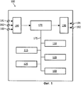
На фиг. 1 показана условно структурная схема примера варианта осуществления системы 100 определения обратной связи по трехмерному местоположению указателя в трехмерной области данных изображения, причем система 100 содержит:In FIG. 1 is a schematic structural diagram of an example embodiment of a
блок 110 отображения для вычисления проекции трехмерной области для отображения на устройстве отображения;a
блок 115 указателя для вычисления двухмерного местоположения указателя на проекции трехмерной области на основе входного сигнала местоположения указателя;a
блок 120 местоположения для вычисления трехмерного местоположения в трехмерной области на основе двухмерного местоположения на проекции трехмерной области; иa
блок 125 тени для определения множества двухмерных местоположений для отображения тени на проекции трехмерной области, причем множество двухмерных местоположений для отображения тени содержит двухмерное местоположение указателя на проекции трехмерной области и множество трехмерных местоположений, вычисленное на основе множества двухмерных местоположений для отображения тени, является связанным.a
Пример варианта осуществления системы 100 дополнительно содержит следующие необязательные блоки:An example embodiment of a
блок 160 управления для управления последовательностью операций в системе 100;a
блок 170 памяти для сохранения данных.a
В одном варианте осуществления системы 100 имеется три входных соединителя 181, 182 и 183 для входящих данных. Первый входной соединитель 181 выполнен с возможностью принимать данные, поступающие от средства хранения данных, например, но не ограничиваясь этим, от жесткого диска, магнитной ленты, флэш-памяти или оптического диска. Второй входной соединитель 182 выполнен с возможностью принимать данные, поступающие от пользовательского входного устройства, например, но не ограничиваясь этим, от мыши (манипулятора) или сенсорного экрана. Третий входной соединитель 183 выполнен с возможностью принимать данные, поступающие от пользовательского входного устройства, такого как клавиатура. Входные соединители 181, 182 и 183 соединены с входным блоком 180 управления.In one embodiment of the
В одном варианте осуществления системы 100 имеется два выходных соединителя 191 и 192 для исходящих данных. Первый выходной соединитель 191 выполнен с возможностью выводить данные на устройство хранения данных, например на жесткий диск, магнитную ленту, флэш-память или оптический диск. Второй выходной соединитель 192 выполнен с возможностью выводить данные на устройство отображения. Выходные соединители 191 и 192 принимают соответствующие данные через выходной блок 190 управления.In one embodiment of the
Специалисту будет понятно, что существует много способов соединения входных устройств с входными соединителями 181, 182 и 183 и соединения выходных устройств с выходными соединителями 191 и 192 системы 100. Эти способы включают в себя, но не ограничиваются этим, проводное и беспроводное соединение, цифровую сеть, например, но не ограничиваясь этим, локальную сеть (LAN), глобальную сеть (WAN), интернет, цифровую телефонную сеть и аналоговую телефонную сеть.One skilled in the art will recognize that there are many ways to connect input devices to input
В одном варианте осуществления системы 100 система 100 содержит блок 170 памяти. Система 100 выполнена с возможностью принимать входные данные от внешних устройств через любой из входных соединителей 181, 182 и 183 и сохранять принятые входные данные в блоке 170 памяти. Загрузка входных данных в блок 170 памяти позволяет получить быстрый доступ к существенным частям данных с помощью блоков системы 100. Входные данные могут включать в себя, например, данные изображения. Блок 170 памяти может быть реализован с помощью различных устройств, например, но не ограничиваясь этим, микросхемы оперативного запоминающего устройства (RAM), микросхемы постоянного запоминающего устройства (ROM) и/или накопителя на жестких дисках и жесткого диска. Блок 170 памяти может быть дополнительно выполнен с возможностью сохранения выходных данных. Выходные данные включают в себя, например, проекцию трехмерной области данных изображения. Блок 170 памяти также выполнен с возможностью принимать данные от и передавать данные к блокам системы 100, блоку 110 отображения, блоку 115 указателя, блоку 120 местоположения, блоку 125 тени и блоку 160 управления посредством шины 175 памяти. Блок 170 памяти дополнительно выполнен с возможностью делать выходные данные доступными внешним устройствам посредством любого из выходных соединителей 191 и 192. Сохранение данных из блоков системы 100 в блоке 170 памяти может выгодно улучшить производительность блоков системы 100, а также повысить скорость передачи выходных данных из блоков системы 100 к внешним устройствам.In one embodiment of the
Альтернативно, система 100 может не содержать блок 170 памяти и шину 175 памяти. Входные данные, используемые системой 100, могут быть предоставлены, по меньшей мере, одним внешним устройством, например внешней памятью или процессором, соединенными с блоками системы 100. Аналогично, выходные данные, формируемые системой 100, могут быть предоставлены, по меньшей мере, одному внешнему устройству, например внешней памяти или процессору, соединенным с блоками системы 100. Блоки системы 100 могут быть выполнены с возможностью принимать данные друг от друга через внутренние соединители или шину данных.Alternatively, the
В одном варианте системы 100 система 100 содержит блок 160 управления для управления последовательностью операций в системе 100. Блок управления может быть выполнен с возможностью принимать управляющие данные от и передавать управляющие данные к блокам системы 100. Например, после приема новых входных данных местоположения указателя блок 115 указателя может быть выполнен с возможностью посылать управляющие данные - «новые принятые входные данные местоположения указателя» в блок 160 управления, а блок 160 управления, в свою очередь, может быть выполнен с возможностью передавать управляющие данные - «получить новое двухмерное местоположение указателя» в блок 125 тени, запрашивая блок 125 тени принять новое двухмерное местоположение указателя от блока 115 указателя. Альтернативно, функция управления может быть реализована в другом блоке системы 100.In one embodiment of the
Данные трехмерного изображения содержат элементы, причем каждый элемент (x, y, z, I) данных содержит трехмерное местоположение (x, y, z), типично представляемое с помощью трех координат x, y, z прямоугольной системы координат в системе координат данных изображения и яркости I в этом местоположении. Объем данных трехмерного изображения может быть определен как объем, содержащий все местоположения (x, y, z), содержащиеся в элементах (x, y, z, I) данных изображения. Элемент данных может быть интерпретирован как воксель, маленький объем, типично куб или кубоид, расположенный в местоположении (x, y, z), которое, например, может быть местоположением вершины или центра вокселя. Объем изображения может быть интерпретирован как объединение всех вокселей.Three-dimensional image data contains elements, with each data element (x, y, z, I) containing a three-dimensional location (x, y, z) typically represented by three x, y, z coordinates of a rectangular coordinate system in the image data coordinate system and I brightness at this location. The volume of three-dimensional image data can be defined as the volume containing all locations (x, y, z) contained in the elements (x, y, z, I) of the image data. A data item may be interpreted as a voxel, a small volume, typically a cube or cuboid, located at a location (x, y, z), which, for example, may be the location of the top or center of the voxel. The volume of the image can be interpreted as the union of all voxels.
Проекция трехмерной области данных изображения может быть вычислена и отображена на устройстве отображения. Проекция трехмерной области данных изображения может быть интерпретирована как совокупность элементов данных двухмерного изображения, где каждый элемент данных двухмерного изображения характеризуется двумя координатами (i, j) в системе координат устройства отображения и яркостью в этом местоположении, возможно, несколькими яркостями для цветных изображений. Специалисту будет понятно, что элемент данных двухмерного изображения может быть интерпретирован как пиксель, то есть маленькая область устройства отображения, как правило, квадрат или прямоугольник, описанная посредством местоположения пикселя, например, координатами (i, j) вершины или центра пикселя и яркостью пикселя, возможно, несколькими яркостями в случае цветных изображений.The projection of the three-dimensional region of the image data can be calculated and displayed on the display device. The projection of the three-dimensional region of the image data can be interpreted as a set of two-dimensional image data elements, where each two-dimensional image data element is characterized by two coordinates (i, j) in the coordinate system of the display device and the brightness at this location, possibly several brightnesses for color images. One skilled in the art will understand that a data element of a two-dimensional image can be interpreted as a pixel, that is, a small area of the display device, typically a square or rectangle described by the location of the pixel, for example, the coordinates (i, j) of the vertex or center of the pixel and the pixel brightness, perhaps a few brightnesses in the case of color images.
Существует много способов вычисления проекции трехмерной области данных изображения. Проекция может быть вычислена с использованием, например, метода проекции максимальной интенсивности (MIP), метода проекции изоповерхности (ISP) и метода прямой объемной визуализация (DVR). В MIP находят трехмерное местоположение максимальной яркости вдоль луча проецирования. Отслеживание луча выполняется от плоскости наблюдения. Яркость пикселя на плоскости наблюдения может быть установлена в значение найденной максимальной яркости вдоль луча. В ISP лучи проецирования прерываются, когда они пересекают интересующую изоповерхность. Изоповерхность определяют как множество уровня функции яркости, то есть как множество всех вокселей, имеющих одинаковую яркость. Более подробную информацию по MIP и ISP можно найти в книге авторов Barthold Lichtenbelt, Randy Crane, Shaz Naqvi, озаглавленной «Introduction to Volume Rendering», опубликованной Hewlett - Packard Professional Books, Prentice Hall; Bk&CD-Rom edition (1998). В DVR функция передачи назначает визуализируемое свойство, например непрозрачность, яркостям, содержащимся в данных изображения. Осуществление DVR описано в статье авторов T. Heet et al, озаглавленной «Generation of Transfer Functions with Stochastic Search Techniques», опубликованной в Proceedings of IEEE Visualization, страницы 227-234, 1996.There are many ways to calculate the projection of a three-dimensional region of image data. The projection can be calculated using, for example, the maximum intensity projection method (MIP), the isosurface projection method (ISP), and the direct volume imaging (DVR) method. In MIP, a three-dimensional location of maximum brightness is found along the projection beam. Beam tracking is performed from the observation plane. The brightness of the pixel on the observation plane can be set to the value of the found maximum brightness along the beam. In ISPs, projection beams are interrupted when they intersect an isosurface of interest. The isosurface is defined as the set of level of the brightness function, that is, as the set of all voxels having the same brightness. More information on MIP and ISP can be found in the book by Barthold Lichtenbelt, Randy Crane, Shaz Naqvi, entitled “Introduction to Volume Rendering”, published by Hewlett - Packard Professional Books, Prentice Hall; Bk & CD-Rom edition (1998). In the DVR, the transfer function assigns a visualized property, such as opacity, to the luminances contained in the image data. DVR implementation is described in an article by T. Heet et al, entitled “Generation of Transfer Functions with Stochastic Search Techniques,” published in Proceedings of IEEE Visualization, pages 227-234, 1996.
Объекты, такие как изоповерхности, могут быть идентифицированы в данных изображения и могут быть использованы для определения объектов в системах координат модели графического процессора. Графический конвейер графического процессора может быть использован для вычисления проекции объектов, содержащихся в системах координат модели. Графический конвейер описан в книге авторов J.D. Foley et al., озаглавленной «Computer graphics: Principles and practice», 2nd Ed., опубликованной Addison - Wesley, Reading, Massachusetts, USA, 1996, далее именуемой как ссылочный документ 1. Специалисту будет понятно, что существует много способов, которые могут быть применены для вычисления проекции трехмерной области данных изображения. Выбор способа вычисления проекции трехмерной области данных изображения не ограничивает объем изобретения.Objects, such as isosurfaces, can be identified in the image data and can be used to define objects in the coordinate systems of the GPU model. The graphics pipeline of the GPU can be used to calculate the projection of objects contained in the coordinate systems of the model. The graphics pipeline is described in a book by JD Foley et al., Entitled "Computer graphics: Principles and practice", 2 nd Ed., Published by Addison - Wesley, Reading, Massachusetts, USA, 1996, hereinafter referred to as
Блок 110 отображения системы 100 выполнен с возможностью вычисления проекции трехмерной области для отображения на устройстве отображения с использованием способа визуализации изображения. Например, блок отображения может быть спроектирован и выполнен с возможностью применения DVR.The
Блок 115 указателя системы 100 выполнен с возможностью вычисления двухмерного местоположения указателя на проекции трехмерной области на основе входного сигнала местоположения указателя. Входной сигнал местоположения указателя может быть получен от навигационного устройства указателя, такого как, но не ограничиваясь этим, мышь, трекбол (шаровой манипулятор), зрительное устройство слежения, сенсорный экран. Специалисту будут понятны способы вычисления двухмерного местоположения указателя на проекции трехмерной области на основе входного сигнала местоположения указателя.The
Блок 120 местоположения системы 100 выполнен с возможностью вычисления трехмерного местоположения в трехмерной области на основе двухмерного местоположения на проекции трехмерной области. Для каждого двухмерного местоположения, например для каждого пикселя, на проекции трехмерной области существует трехмерное местоположение, например воксель, в трехмерной области, соответствующее упомянутому двухмерному местоположению. В одном варианте осуществления системы 100 блок 120 местоположения выполнен с возможностью вычисления трехмерного местоположения в трехмерной области на основе двухмерного местоположения на проекции трехмерной области с использованием значения глубины двухмерного местоположения на проекции трехмерной области, сохраненного в буфере глубины. Значение z(i,j) глубины двухмерного местоположения (i,j) содержит координату z соответствующего трехмерного местоположения. Обычно это координата z в так называемой системе нормализованных координат устройства (NDC). В этом варианте осуществления блок местоположения выполнен с возможностью преобразования трех координат (i,j,z(i,j)) обратно в так называемую мировую (внешнюю) или универсальную систему координат с использованием преобразований графического конвейера, описанного, например, в ссылочном документе 1.The
Альтернативно, в одном варианте осуществления системы 100 блок 120 местоположения выполнен с возможностью вычисления трехмерного местоположения в трехмерной области на основе двухмерного местоположения на проекции трехмерной области с использованием отслеживания лучей. Например, в изображении, визуализированном с использованием MIP, яркость в двухмерном местоположении на плоскости обзора устанавливается в значение максимальной яркости вдоль луча, отслеживаемого от упомянутого двухмерного местоположения на плоскости обзора в направлении, по существу, перпендикулярном плоскости обзора. Вычисления, как правило, выполняются в мировой системе координат. Плоскость обзора отображается на устройстве отображения для отображения проекции трехмерной области на устройстве отображения. Таким образом, трехмерное местоположение в трехмерной области, вычисленное на основе двухмерного местоположения на проекции трехмерной области, причем двухмерное местоположение на проекции трехмерной области соответствует местоположению на плоскости обзора, является трехмерным местоположением максимальной яркости на луче, отслеживаемом от двухмерного местоположения на плоскости обзора, по существу, перпендикулярной плоскости обзора.Alternatively, in one embodiment of the
Специалисту также будет понятно, что существует много способов вычисления трехмерного местоположения в трехмерной области на основе двухмерного местоположения на проекции трехмерной области, и то, что описанные способы, если они не заявлены в качестве признака варианта осуществления, иллюстрируют изобретение без ограничения объема формулы изобретения.One skilled in the art will also understand that there are many methods for calculating a three-dimensional location in a three-dimensional region based on a two-dimensional location on a projection of a three-dimensional region, and that the described methods, unless stated as a feature of an embodiment, illustrate the invention without limiting the scope of the claims.
Блок 125 тени системы 100 выполнен с возможностью вычисления множества двухмерных местоположений для отображения тени на проекции трехмерной области, причем множество двухмерных местоположений для отображения тени содержит двухмерные местоположения указателя на проекции трехмерной области и множество трехмерных местоположений, вычисленное на основе множества двухмерных местоположений для отображения тени, является связанным, таким образом определяя обратную связь по трехмерному местоположению указателя в трехмерной области данных изображения. При работе блок 125 тени выполнен с возможностью принимать двухмерное местоположение указателя. Блок 125 тени выполнен с возможностью определять множество возможных двухмерных местоположений для отображения тени на проекции трехмерной области. Блок 120 местоположения выполнен с возможностью вычисления трехмерных местоположений возможных двухмерных местоположений, далее именуемых возможными трехмерными местоположениями. Блок 125 тени дополнительно выполнен с возможностью получения множества вычисленных возможных трехмерных местоположений, содержащих трехмерное местоположение указателя. Используя определение связанности, блок 125 тени определяет связанное множество возможных трехмерных местоположений, содержащих трехмерное местоположение указателя. Например, если интерпретировать возможные трехмерные местоположения как воксели, то может быть определено наибольшее 26-связаное множество возможных вокселей. Два кубовидных вокселя являются 26-связанными, если они делят, по меньшей мере, одну общую вершину. Возможные двухмерные местоположения, соответствующие возможным трехмерным местоположениям, содержащимся в наибольшем связанном множестве возможных трехмерных местоположений, содержащих трехмерное местоположение указателя, определяют множество двухмерных местоположений для отображения тени на проекции трехмерной области.The
Специалисту будет понятно, что существует множество подходящих определений связанности, которые могут быть применены в вариантах осуществления системы 100. Описанная система 100, использующая 26-связанность, иллюстрирует вариант осуществления системы 100 и ее не следует понимать как ограничивающую объем изобретения.One skilled in the art will recognize that there are many suitable definitions of connectivity that can be applied to embodiments of
Тень может быть создана, например, с помощью изменения яркости и/или цвета пикселей, соответствующих двухмерным местоположениям из определенного множества двухмерных местоположений для отображения тени на проекции трехмерной области.A shadow can be created, for example, by changing the brightness and / or color of pixels corresponding to two-dimensional locations from a specific set of two-dimensional locations to display the shadow on the projection of the three-dimensional region.
Система 100 также может быть выполнена с возможностью дополнительного отображения обратной связи по трехмерному местоположению указателя в трехмерной области данных изображения. Например, система 100 может быть дополнительно выполнена с возможностью отображения двухмерного местоположения указателя и координат трехмерного местоположения указателя.
В одном варианте осуществления системы 100 множество двухмерных местоположений для отображения тени является связанным. В принципе, возможно, чтобы множество возможных двухмерных местоположений не было связанным, в то время как множество возможных трехмерных местоположений, вычисленное на основе этих возможных двухмерных местоположений, являлось бы связанным множеством. Такая ситуация скорее всего имеет место тогда, когда размер вокселей, например длина грани кубического вокселя, намного больше, например в 5 раз больше, чем размер пикселей, например чем длина стороны квадратного пикселя. Для обеспечения того, чтобы множество двухмерных местоположений было связанным, блок 125 тени может быть выполнен с возможностью сохранять только один связанный компонент множества двухмерных местоположений для отображения тени на проекции трехмерной области. Критерий связанности может быть, например, критерием 4-связанности. Два пикселя являются 4-связанными, если они делят одну общую сторону.In one embodiment of the
Специалисту будет понятно, что существуют дополнительные условия, которые могут быть наложены на множество двухмерных местоположений для отображения тени и/или на множество трехмерных местоположений, вычисленных на основе двухмерных местоположений. Объем формулы изобретения не зависит от этих дополнительных условий.One skilled in the art will understand that there are additional conditions that can be imposed on a plurality of two-dimensional locations to display a shadow and / or on a plurality of three-dimensional locations calculated based on two-dimensional locations. The scope of the claims is independent of these additional conditions.
В одном варианте осуществления системы 100 множество двухмерных местоположений для отображения тени содержится в окружности с центром в двухмерном местоположении указателя на проекции трехмерной области. Длина диаметра окружности определяет максимальный размер тени. Возможные двухмерные местоположения являются местоположениями внутри окружности. Радиус окружности может быть определен заранее или может быть определен системой 100, например, на основе свойства отображаемой проекции или на основе входных данных пользователя. Специалисту будет понятно, что формы, отличные от окружности, также могут быть приняты в рассмотрение.In one embodiment of the
В одном варианте осуществления системы 100 блок 125 тени дополнительно выполнен с возможностью определения цвета тени на основе характеристики множества двухмерных местоположений для отображения тени или на основе характеристики множества трехмерных местоположений. Например, блок 125 тени дополнительно может быть выполнен с возможностью вычисления трехмерного тензора моментов инерции множества трехмерных местоположений. Если отношение наибольшего главного значения к наименьшему главному значению больше заданного порогового значения, например больше 3, то можно считать, что тень указывает удлиненную структуру и может быть показана в первом цвете. В противном случае можно считать, что тень указывает овальную структуру и может быть показана во втором цвете. В другом варианте осуществления цвет тени может быть основан на отношении главных компонентов тензора двухмерной структуры, вычисленной в двухмерном местоположении указателя. Определение, вычисление и свойства тензоров структуры, полученных из данных изображения, описываются в статье «A tensor approach for local structure analysis in multi-dimensional images» авторов H. Haubecker и B. Jahne, опубликованной в «3D Image Analysis and Synthesis' 96», под редакцией B. Girod et al., Sankt Augustin 1996, 171 - 178. Другие характеристики, например кривизна поверхности, определенная на основе множества трехмерных местоположений, средняя яркость трехмерных местоположений, содержащихся во множестве трехмерных местоположений, также могут быть применены для определения цвета тени.In one embodiment of the
На фиг. 2 показана проекция трехмерной области данных изображения, содержащая пример структуры, и проиллюстрирован пример обратной связи по трехмерному местоположению указателя в трехмерной области. Местоположение указателя указывается с помощью символа креста и таблички M1. Ниже указателя также отображается глубина “1232.3 (3D)” трехмерного местоположения указателя. Интересующая структура, указанная с помощью указателя M1, является кровеносным сосудом 1. Отображаемая тень 2 четко и однозначно показывает, что структура, указанная с помощью указателя, является кровеносным сосудом 1.In FIG. 2 shows a projection of a three-dimensional region of image data containing an example of a structure, and an example of feedback on a three-dimensional location of a pointer in a three-dimensional region is illustrated. The location of the pointer is indicated by the cross symbol and plate M1. The depth of “1232.3 (3D)” of the three-dimensional location of the pointer is also displayed below the pointer. The structure of interest indicated by the pointer M1 is a
На фиг. 3 показаны две идентичные проекции трехмерной области данных изображения, содержащие кровеносный сосуд и зашумленную структуру, и проиллюстрированы два примера обратных связей по двум трехмерным местоположениям указателя в трехмерной области. На обеих проекциях местоположение указателя указано с помощью символа креста и таблички M1. Ниже каждого указателя также отображается глубина трехмерного местоположения каждого указателя. Интересующая структура является кровеносным сосудом 1. Однако несколькими сантиметрами выше кровеносного сосуда также находится шум и, таким образом, с трудом видимая структура. На первой проекции 31 не видно никакой тени вокруг символа креста, указывающего позицию указателя. Это происходит потому, что указатель не указывает кровеносный сосуд 1, а указывает небольшую часть 3 зашумленной структуры выше кровеносного сосуда 1. На второй проекции 32 тень 2, отображаемая на кровеносном сосуде 1, четко и однозначно указывает местоположение указателя. Небольшая часть 3 зашумленной структуры также может быть видна. Этот пример иллюстрирует то, что обратная связь тени очень полезна для выбора интересующей структуры, например, с помощью щелчка мышью, когда указатель указывает интересующую структуру. Без обратной связи тени было бы трудно определить, что структура, указанная на первой проекции 31, является небольшой частью 3 зашумленной структуры, а не кровеносным сосудом 1. Это могло бы привести к выбору неверной структуры.In FIG. 3 shows two identical projections of a three-dimensional region of image data containing a blood vessel and a noisy structure, and two examples of feedbacks of two three-dimensional pointer locations in the three-dimensional region are illustrated. On both projections, the location of the pointer is indicated by the cross symbol and the M1 plate. Below each pointer, the depth of the three-dimensional location of each pointer is also displayed. The structure of interest is
На фиг. 4 показана проекция трехмерной области данных изображения, содержащей тонкий кровеносный сосуд поверх занятого фона, и проиллюстрирован пример обратной связи по трехмерному местоположению указателя в трехмерной области. Местоположение указано символом креста и табличкой M1. Ниже указателя также отображается глубина “145.0 (3D)” трехмерного местоположения указателя. Интересующая структура, указанная с помощью указателя, является тонким кровеносным сосудом 1, отображаемым поверх занятого фона, содержащего множество структур. Отображаемая тень 2 четко и однозначно показывает, что структура, указанная с помощью указателя, является кровеносным сосудом 1. Размер тени больше, чем в двух предыдущих примерах, для того чтобы лучше визуализировать интересующую структуру.In FIG. 4 shows a projection of a three-dimensional region of image data containing a thin blood vessel over a busy background, and an example of feedback on a three-dimensional location of a pointer in a three-dimensional region is illustrated. The location is indicated by the cross symbol and the M1 sign. Below the pointer, the depth “145.0 (3D)” of the three-dimensional location of the pointer is also displayed. The structure of interest indicated by the pointer is a
Специалисту также будет понятно, что другие варианты осуществления системы 100 также возможны. В числе прочего также возможно переопределить блоки системы и перераспределить их функции. Например, в одном варианте осуществления системы 100 функции блока 120 местоположения могут быть объединены с функциями блока 125 тени. В еще одном варианте осуществления системы 100 блок 125 тени может быть разделен на блок генерации для генерирования возможных двухмерных местоположений для отображения тени и на блок оценки для оценки возможных двухмерных местоположений для отображения тени. В еще одном варианте осуществления системы 100 может быть множество блоков тени, заменяющих блок 125 тени. Каждый блок тени из множества блоков тени может быть выполнен с возможностью применения различных критериев связанности.One skilled in the art will also appreciate that other embodiments of the
Блоки системы 100 могут быть реализованы с использованием процессора. Обычно их функции выполняются под управлением программного продукта программного обеспечения. При выполнении программный продукт программного обеспечения обычно загружается в память, подобную RAM, и выполняется оттуда. Программа может быть загружена из фоновой памяти, подобной ROM, жесткого диска или магнитного и/или оптического хранилища или может быть загружена через сеть наподобие интернета.Blocks of the
Дополнительно, интегральная схема, специфичная для приложения, может обеспечить описанную функциональность.Additionally, an application-specific integrated circuit may provide the described functionality.
На фиг. 5 показана схема последовательности операций примера осуществления способа 500 определения обратной связи по трехмерному местоположению указателя в трехмерной области данных изображения. Способ 500 начинается с этапа 510 отображения для вычисления проекции трехмерной области для отображения на устройстве отображения. После этапа 510 отображения способ начинает цикл обратной связи и переходит к этапу 515 указателя для вычисления двухмерного местоположения указателя на проекции трехмерной области на основе входного сигнала местоположения указателя. После этапа 515 указателя способ переходит к этапу 525 тени для определения множества двухмерных местоположений для отображения тени на проекции трехмерной области, причем множество двухмерных местоположений для отображения тени содержит двухмерное местоположение указателя и множество трехмерных местоположений, вычисленное на основе множества двухмерных местоположений для отображения тени, является связанным. При определении множества двухмерных местоположений для отображения тени способ 500 выполняет этап 520 местоположения для того, чтобы вычислить трехмерные местоположения возможных двухмерных местоположений. Множество двухмерных местоположений для отображения тени определяют на основе вычисленных трехмерных местоположений возможных двухмерных местоположений. После определения множества двухмерных местоположений для отображения тени способ 500 ожидает появления нового входного сигнала местоположения указателя и затем переходит к этапу 515 указателя. Альтернативно, после приема команды выйти из цикла обратной связи способ завершается.In FIG. 5 is a flowchart of an example embodiment of a
Порядок этапов в способе 500 не является обязательным, поэтому специалист может поменять порядок следования некоторых этапов или выполнить некоторые этапы одновременно с использованием моделей поточной обработки, мультипроцессорных систем или множества процессоров без отступления от идеи настоящего изобретения. Дополнительно, два или более этапов способа 500 настоящего изобретения могут быть объединены в один этап. Дополнительно, этап способа 500 настоящего изобретения может быть разделен на множество этапов.The order of steps in
На фиг. 6 схематически показан пример варианта осуществления устройства 600 захвата изображения, использующего систему 100, причем упомянутое устройство 600 захвата изображения содержит блок 610 захвата изображения, связанный посредством внутренней связи с системой 100, входным соединителем 601 и выходным соединителем 602. Эта компоновка повышает возможности устройство 600 захвата изображения, обеспечивая упомянутое устройство 600 захвата изображения преимущественными возможностями системы 100 определения обратной связи по трехмерному местоположению в трехмерной области данных изображения. Примеры устройства захвата изображения включают в себя, но не ограничиваясь этим, систему CT (компьютерная томография), рентгенографическую систему, систему MRI (отображение магнитного резонанса), систему US (ультразвук), систему PET (томография на основе метода позитронной эмиссии), систему SPECT (томография на основе эмиссии одного фотона), систему MN (ядерная медицина).In FIG. 6 schematically shows an example embodiment of an
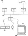
На фиг. 7 показан пример варианта осуществления рабочей станции 700. Рабочая станция содержит системную шину 701. Процессор 710, память 720, дисковый входной/выходной (I/O) адаптер 730 и пользовательский интерфейс (UI) 740 оперативно соединены с системной шиной 701. Дисковое устройство 731 хранения оперативно соединено дисковым адаптером 730 I/O. Клавиатура 741, мышь 742 и устройство 743 отображения оперативно связаны с UI 740. Система 100 согласно настоящему изобретению, реализованная в виде компьютерной программы, сохраняется на дисковом устройстве 731 хранения. Рабочая станция 700 выполнена с возможностью загрузки программы и входных данных в память 720 и выполнения программы на процессоре 710. Пользователь может вводить информацию в рабочую станцию 700, используя клавиатуру 741 и/или мышь 742. Рабочая станция выполнена с возможностью выводить информацию на устройство 743 отображения и/или на диск 731. Специалисту будет понятно, что существует множество других вариантов осуществления рабочей станции 700, известных в уровне техники, и что настоящий вариант осуществления служит для иллюстрации настоящего изобретения и его не следует воспринимать в качестве ограничивающего изобретение.In FIG. 7 shows an example embodiment of a
Следует отметить, что вышеупомянутые варианты осуществления иллюстрируют, а не ограничивают изобретение, и что специалисты смогут разработать альтернативные варианты осуществления без отклонения от объема изобретения, определяемого прилагаемой формулой изобретения. В формуле изобретения любые ссылочные символы, помещенные в скобки, не должны пониматься как ограничивающие изобретение. Термин «содержащий» не исключает наличия элементов или этапов, не перечисленных в формуле изобретения или в описании. Указание элементов в единственном числе не исключает возможности наличия множества таких элементов. Изобретение может быть реализовано с помощью аппаратных средств, содержащих несколько различных элементов, и с помощью средств программируемого компьютера. В пунктах формулы изобретения, перечисляющих несколько блоков, некоторые из этих блоков могут быть реализованы с помощью одного и того же средства аппаратного или программного обеспечения. Использование терминов первый, второй, третий и так далее не указывает на наличие какого-либо порядка. Эти термины следует понимать в качестве обозначений.It should be noted that the above embodiments illustrate, but not limit, the invention, and that those skilled in the art will be able to develop alternative embodiments without departing from the scope of the invention as defined by the appended claims. In the claims, any reference characters in parentheses should not be construed as limiting the invention. The term “comprising” does not exclude the presence of elements or steps not listed in the claims or in the description. Indication of elements in the singular does not exclude the possibility of the presence of many such elements. The invention can be implemented using hardware containing several different elements, and using the means of a programmable computer. In the claims enumerating several blocks, some of these blocks can be implemented using the same hardware or software. The use of the terms first, second, third and so on does not indicate the presence of any order. These terms should be understood as designations.
Claims (11)
блок (110) отображения для вычисления проекции трехмерной области для отображения на устройстве отображения;
блок (115) указателя для вычисления двухмерного местоположения указателя на проекции трехмерной области на основе входного сигнала местоположения указателя;
блок (120) местоположения для вычисления трехмерного местоположения в трехмерной области на основе и согласно двухмерному местоположению на проекции трехмерной области и
блок (125) тени для (i) определения множества возможных двухмерных местоположений для отображения тени на проекции трехмерной области, причем множество возможных двухмерных местоположений основано на и содержит двухмерное местоположение указателя, (ii) вычисления, с использованием блока местоположения, множества возможных трехмерных местоположений на основе множества возможных двухмерных местоположений, (iii) определения, на основе определения связанности, связанного подмножества из множества возможных трехмерных местоположений, содержащего возможные трехмерные местоположения, которые связаны в трехмерной области, (iv) установления соответствующего подмножества из множества возможных двухмерных местоположений, содержащего возможные двухмерные местоположения, которые соответствуют возможным трехмерным местоположениям связанного подмножества, и (v) отображения тени на проекции трехмерной области на основе возможных двухмерных местоположений соответствующего подмножества для предоставления обратной связи по трехмерному местоположению указателя в трехмерной области данных изображения.1. A system (100) for determining feedback from a three-dimensional location of a pointer in a three-dimensional region of image data, comprising:
a display unit (110) for calculating a projection of a three-dimensional region for display on a display device;
a block (115) of a pointer for calculating a two-dimensional location of the pointer on the projection of the three-dimensional region based on the input signal location of the pointer;
a location unit (120) for calculating a three-dimensional location in the three-dimensional region based on and according to the two-dimensional location on the projection of the three-dimensional region and
a shadow block (125) for (i) determining a plurality of possible two-dimensional locations for displaying a shadow on a projection of a three-dimensional region, wherein a plurality of possible two-dimensional locations is based on and contains a two-dimensional pointer location, (ii) computing, using a location block, a plurality of possible three-dimensional locations on based on the set of possible two-dimensional locations, (iii) determining, based on the determination of connectedness, a related subset of the set of possible three-dimensional locations, containing containing possible three-dimensional locations that are connected in the three-dimensional region, (iv) establishing a corresponding subset of the set of possible two-dimensional locations containing possible two-dimensional locations that correspond to possible three-dimensional locations of the associated subset, and (v) displaying a shadow on the projection of the three-dimensional region based on possible two-dimensional locations of the corresponding subset to provide feedback on the three-dimensional location of the pointer in the three-dimensional region five image data.
этап (510) отображения, на котором вычисляют проекцию трехмерной области для отображения на устройстве отображения;
этап (515) указателя, на котором вычисляют двухмерное местоположение указателя на проекции трехмерной области на основе входного сигнала местоположения указателя;
этап (520) определения местоположения, на котором вычисляют трехмерное местоположение в трехмерной области на основе и согласно двухмерному местоположению на проекции трехмерной области; и
этап (525) тени, на котором (i) определяют множество возможных двухмерных местоположений для отображения тени на проекции трехмерной области, причем множество возможных двухмерных местоположений основано на и содержит двухмерное местоположение указателя, (ii) вычисляют, с использованием этапа определения местоположения, множество возможных трехмерных местоположений на основе множества возможных двухмерных местоположений, (iii) определяют, на основе определения связанности, связанное подмножество из множества возможных трехмерных местоположений, содержащее возможные трехмерные местоположения, которые связаны в трехмерной области, (iv) устанавливают соответствующее подмножество из множества возможных двухмерных местоположений, содержащее возможные двухмерные местоположения, которые соответствуют возможным трехмерным местоположениям связанного подмножества, и (v) отображают тень на проекции трехмерной области на основе возможных двухмерных местоположений соответствующего подмножества для предоставления обратной связи по трехмерному местоположению указателя в трехмерной области данных изображения.10. A method (500) for determining feedback from a three-dimensional location of a pointer in a three-dimensional region of image data, comprising the following steps:
a display step (510) in which a projection of the three-dimensional region for displaying on the display device is calculated;
step (515) of the pointer, which calculates the two-dimensional location of the pointer on the projection of the three-dimensional region based on the input signal location of the pointer;
step (520) determining the location at which calculate the three-dimensional location in the three-dimensional region based on and according to the two-dimensional location on the projection of the three-dimensional region; and
a shadow step (525), in which (i) a plurality of possible two-dimensional locations are determined for displaying a shadow on a projection of a three-dimensional region, wherein a plurality of possible two-dimensional locations are based on and contains a two-dimensional pointer location, (ii) calculating, using the location determination step, a plurality of possible three-dimensional locations based on the set of possible two-dimensional locations, (iii) determine, based on the determination of connectivity, a related subset of the set of possible three-dimensional locations location containing possible three-dimensional locations that are connected in the three-dimensional region, (iv) establish a corresponding subset of the set of possible two-dimensional locations, containing possible two-dimensional locations that correspond to possible three-dimensional locations of the associated subset, and (v) display a shadow on the projection of the three-dimensional region based on possible two-dimensional locations of the corresponding subset to provide feedback on the three-dimensional location of the pointer in the dimensional region of image data.
этап отображения, на котором вычисляют проекции трехмерной области для отображения на устройстве отображения;
этап указателя, на котором вычисляют двухмерное местоположение указателя на проекции трехмерной области на основе входного сигнала местоположения указателя;
этап определения местоположения, на котором вычисляют трехмерное местоположение в трехмерной области на основе и согласно двухмерному местоположению на проекции трехмерной области; и
этап (525) тени, на котором (i) определяют множество возможных двухмерных местоположений для отображения тени на проекции трехмерной области, причем множество возможных двухмерных местоположений основано на и содержит двухмерные местоположения указателя, (ii) вычисляют, с использованием этапа определения местоположения, множество возможных трехмерных местоположений на основе множества возможных двухмерных местоположений, (iii) определяют, на основе определения связанности, связанное подмножество из множества возможных трехмерных местоположений, содержащее возможные трехмерные местоположения, которые связаны в трехмерной области, (iv) устанавливают соответствующее подмножество из множества возможных двухмерных местоположений, содержащее возможные двухмерные местоположения, которые соответствуют возможным трехмерным местоположениям связанного подмножества, и (v) отображают тень на проекции трехмерной области на основе возможных двухмерных местоположений соответствующего подмножества для предоставления обратной связи по трехмерному местоположению указателя в трехмерной области данных изображения. 11. A computer-readable medium containing instructions stored thereon, which, when executed by a computer device, instruct the computer device to perform a method for determining feedback by the three-dimensional location of the pointer in the three-dimensional region of image data, the computer device comprising a processing unit and a memory, the instructions after they are loaded into memory, enable said processing unit to execute a method comprising:
a display step in which projections of a three-dimensional region for display on a display device are calculated;
a pointer step, in which a two-dimensional location of the pointer on the projection of the three-dimensional region is calculated based on the input signal of the location of the pointer;
a location determination step in which a three-dimensional location in the three-dimensional region is calculated based on and according to the two-dimensional location on the projection of the three-dimensional region; and
a shadow step (525), in which (i) a plurality of possible two-dimensional locations are determined for displaying a shadow on a projection of a three-dimensional region, wherein a plurality of possible two-dimensional locations are based on and contains two-dimensional pointer locations, (ii) a plurality of possible are calculated using the location determination step three-dimensional locations based on the set of possible two-dimensional locations, (iii) determine, based on the determination of connectivity, a related subset of the set of possible three-dimensional locations location containing possible three-dimensional locations that are connected in the three-dimensional region, (iv) establish a corresponding subset of the set of possible two-dimensional locations, containing possible two-dimensional locations that correspond to possible three-dimensional locations of the associated subset, and (v) display a shadow on the projection of the three-dimensional region based on possible two-dimensional locations of the corresponding subset to provide feedback on the three-dimensional location of the pointer in the dimensional region of image data.
Applications Claiming Priority (3)
| Application Number | Priority Date | Filing Date | Title |
|---|---|---|---|
| EP06121515.8 | 2006-09-29 | ||
| EP06121515 | 2006-09-29 | ||
| PCT/IB2007/053859 WO2008038215A2 (en) | 2006-09-29 | 2007-09-24 | 3d connected shadow mouse pointer |
Publications (2)
| Publication Number | Publication Date |
|---|---|
| RU2009116262A RU2009116262A (en) | 2010-11-10 |
| RU2479012C2 true RU2479012C2 (en) | 2013-04-10 |
Family
ID=39230644
Family Applications (1)
| Application Number | Title | Priority Date | Filing Date |
|---|---|---|---|
| RU2009116262/08A RU2479012C2 (en) | 2006-09-29 | 2007-09-24 | Three-dimensional shadow mouse pointer |
Country Status (6)
| Country | Link |
|---|---|
| US (1) | US8493389B2 (en) |
| EP (1) | EP2074499B1 (en) |
| JP (1) | JP5373612B2 (en) |
| CN (1) | CN101517526B (en) |
| RU (1) | RU2479012C2 (en) |
| WO (1) | WO2008038215A2 (en) |
Families Citing this family (19)
| Publication number | Priority date | Publication date | Assignee | Title |
|---|---|---|---|---|
| IT1395344B1 (en) * | 2009-05-28 | 2012-09-14 | Geosoft S R L | METHOD OF RETURN PHOTOGRAMMETRIC ASSISTED BY CLOUD OF POINTS AND ITS APPARATUS. |
| JP5898842B2 (en) | 2010-01-14 | 2016-04-06 | 任天堂株式会社 | Portable information processing device, portable game device |
| EP2355526A3 (en) | 2010-01-14 | 2012-10-31 | Nintendo Co., Ltd. | Computer-readable storage medium having stored therein display control program, display control apparatus, display control system, and display control method |
| JP5800501B2 (en) | 2010-03-12 | 2015-10-28 | 任天堂株式会社 | Display control program, display control apparatus, display control system, and display control method |
| US8384770B2 (en) | 2010-06-02 | 2013-02-26 | Nintendo Co., Ltd. | Image display system, image display apparatus, and image display method |
| GB201020077D0 (en) * | 2010-11-26 | 2011-01-12 | Siemens Medical Solutions | Correlating planar to tomograph data |
| JP6021296B2 (en) * | 2010-12-16 | 2016-11-09 | 任天堂株式会社 | Display control program, display control device, display control system, and display control method |
| US8854357B2 (en) * | 2011-01-27 | 2014-10-07 | Microsoft Corporation | Presenting selectors within three-dimensional graphical environments |
| JP5788228B2 (en) * | 2011-06-06 | 2015-09-30 | 株式会社東芝 | 3D display processing system |
| US9746989B2 (en) * | 2011-10-13 | 2017-08-29 | Toshiba Medical Systems Corporation | Three-dimensional image processing apparatus |
| US8732620B2 (en) | 2012-05-23 | 2014-05-20 | Cyberlink Corp. | Method and system for a more realistic interaction experience using a stereoscopic cursor |
| US8957855B2 (en) | 2012-06-25 | 2015-02-17 | Cyberlink Corp. | Method for displaying a stereoscopic cursor among stereoscopic objects |
| CA2887360A1 (en) * | 2012-10-05 | 2014-04-10 | Nathaniel J. Kemp | Methods and systems for establishing parameters, playback, and artifact removal three-dimensional imaging |
| JP5947707B2 (en) * | 2012-12-27 | 2016-07-06 | 富士フイルム株式会社 | Virtual endoscopic image display apparatus and method, and program |
| JP6245840B2 (en) * | 2013-05-14 | 2017-12-13 | 東芝メディカルシステムズ株式会社 | Image processing apparatus, method, program, and stereoscopic image display apparatus |
| WO2017097682A1 (en) * | 2015-12-07 | 2017-06-15 | Koninklijke Philips N.V. | An apparatus and method for detecting a tool |
| GB2555468B (en) * | 2016-10-31 | 2020-05-27 | Bitplane Ag | Visualization system and method for 3D scenes |
| EP3340023B1 (en) * | 2016-12-22 | 2020-02-12 | Dassault Systèmes | Fast manipulation of objects in a three-dimensional scene |
| CN108984262B (en) * | 2018-07-12 | 2021-04-13 | 宁波视睿迪光电有限公司 | Three-dimensional pointer creating method and device and electronic equipment |
Citations (1)
| Publication number | Priority date | Publication date | Assignee | Title |
|---|---|---|---|---|
| RU2005107609A (en) * | 2004-03-19 | 2006-08-27 | Майкрософт Корпорейшн (Us) | AUTOMATIC HEIGHT ADJUSTMENT FOR ELECTRONIC FEATURES AND COORDINATING INDICATOR DEVICES OF THE TYPE "MOUSE" USING TO DISPLAY INFORMATION ON THE DISPLAY SCREEN |
Family Cites Families (18)
| Publication number | Priority date | Publication date | Assignee | Title |
|---|---|---|---|---|
| AU632628B2 (en) * | 1989-11-13 | 1993-01-07 | Apple Computer, Inc. | Method and apparatus for a computer display system with a three dimensional cursor shadow |
| US5359703A (en) * | 1990-08-02 | 1994-10-25 | Xerox Corporation | Moving an object in a three-dimensional workspace |
| US5264836A (en) * | 1991-01-15 | 1993-11-23 | Apple Computer, Inc. | Three dimensional cursor |
| JPH0660164A (en) * | 1992-08-06 | 1994-03-04 | Hitachi Ltd | Three-dimensional shape processing system |
| US5422986A (en) * | 1993-05-12 | 1995-06-06 | Pacific Data Images, Inc. | Method for generating soft-edge mattes for visual elements of images |
| GB2282944B (en) * | 1993-09-30 | 1998-01-28 | Intel Corp | Remote display of objects and cursor movement in a conferencing system |
| JPH0816137A (en) | 1994-06-29 | 1996-01-19 | Nec Corp | Three-dimensional coordinate input device and cursor display control system |
| JP2985847B2 (en) | 1997-10-17 | 1999-12-06 | 日本電気株式会社 | Input device |
| JP2000182081A (en) * | 1998-12-14 | 2000-06-30 | Suzuki Motor Corp | Method and device for generating analysis model, and storage medium stored with analysis model generating program or analysis model data |
| US6971071B1 (en) | 1999-06-10 | 2005-11-29 | Microsoft Corporation | System and method for implementing an image ancillary to a cursor |
| US6918087B1 (en) * | 1999-12-16 | 2005-07-12 | Autodesk, Inc. | Visual clues to navigate three-dimensional space in a computer-implemented graphics system |
| US6487432B2 (en) * | 2000-12-04 | 2002-11-26 | Ge Medical Systems Global Technologies Company Llc | Method and system for selecting and displaying medical image data |
| US7126578B1 (en) * | 2001-05-17 | 2006-10-24 | Adobe Systems Incorporated | Combining raster and vector data in the presence of transparency |
| US7046254B2 (en) | 2002-01-28 | 2006-05-16 | International Business Machines Corporation | Displaying transparent resource aids |
| US7313259B2 (en) * | 2003-11-26 | 2007-12-25 | General Electric Company | Method, system and computer program product for multi-modality registration using virtual cursors |
| JP4408794B2 (en) * | 2004-11-18 | 2010-02-03 | ザイオソフト株式会社 | Image processing program |
| US7711165B2 (en) * | 2005-07-28 | 2010-05-04 | Siemens Medical Solutions Usa, Inc. | System and method for coronary artery segmentation of cardiac CT volumes |
| US7675518B1 (en) * | 2006-09-05 | 2010-03-09 | Adobe Systems, Incorporated | System and method for generating image shadows with ray-coherent integration of extruded transparency maps |
-
2007
- 2007-09-24 RU RU2009116262/08A patent/RU2479012C2/en not_active IP Right Cessation
- 2007-09-24 WO PCT/IB2007/053859 patent/WO2008038215A2/en active Application Filing
- 2007-09-24 CN CN2007800357445A patent/CN101517526B/en active Active
- 2007-09-24 JP JP2009529818A patent/JP5373612B2/en active Active
- 2007-09-24 US US12/442,761 patent/US8493389B2/en active Active
- 2007-09-24 EP EP07826509.7A patent/EP2074499B1/en active Active
Patent Citations (1)
| Publication number | Priority date | Publication date | Assignee | Title |
|---|---|---|---|---|
| RU2005107609A (en) * | 2004-03-19 | 2006-08-27 | Майкрософт Корпорейшн (Us) | AUTOMATIC HEIGHT ADJUSTMENT FOR ELECTRONIC FEATURES AND COORDINATING INDICATOR DEVICES OF THE TYPE "MOUSE" USING TO DISPLAY INFORMATION ON THE DISPLAY SCREEN |
Non-Patent Citations (1)
| Title |
|---|
| JI-YOUNG О. et al. «Moving Objects with 2D Input Device in CAD Systems and Desktop Virtual Environments // Proceedings of Graphics Interface. - 2005, том 112. COHEN M. et al. Volume Seedlings // Proceedings of the symposium on interactive 3D graphics. - 29.03.1992. ЧУМАЧЕНКО И.Н. 3ds max 6. Второе издание, исправленное и дополненное. - 2004, NT Press. * |
Also Published As
| Publication number | Publication date |
|---|---|
| WO2008038215A2 (en) | 2008-04-03 |
| WO2008038215A3 (en) | 2008-09-18 |
| US20100033429A1 (en) | 2010-02-11 |
| CN101517526B (en) | 2012-06-06 |
| CN101517526A (en) | 2009-08-26 |
| EP2074499B1 (en) | 2015-01-07 |
| JP5373612B2 (en) | 2013-12-18 |
| JP2010505175A (en) | 2010-02-18 |
| EP2074499A2 (en) | 2009-07-01 |
| US8493389B2 (en) | 2013-07-23 |
| RU2009116262A (en) | 2010-11-10 |
Similar Documents
| Publication | Publication Date | Title |
|---|---|---|
| RU2479012C2 (en) | Three-dimensional shadow mouse pointer | |
| EP2080170B1 (en) | Combined intensity projection | |
| US8805034B2 (en) | Selection of datasets from 3D renderings for viewing | |
| US9965838B2 (en) | Caliper for measuring objects in an image | |
| US10692272B2 (en) | System and method for removing voxel image data from being rendered according to a cutting region | |
| US10872460B1 (en) | Device and system for volume visualization and interaction in a virtual reality or augmented reality environment | |
| US10891787B2 (en) | Apparatus and method for creating biological model | |
| US10026220B2 (en) | Layered lightfields for occlusion handling | |
| EP2727078B1 (en) | Zooming of medical images | |
| JP5122650B2 (en) | Path neighborhood rendering | |
| CN109643441B (en) | Image processing apparatus, image processing method, computer-readable storage medium, and image processing system | |
| US9035945B1 (en) | Spatial derivative-based ray tracing for volume rendering | |
| US7609876B2 (en) | Virtual grid alignment of sub-volumes | |
| JP6443574B1 (en) | Ray casting program, search control data, search control data generation method, and ray casting apparatus | |
| Durisetti et al. | Evaluation of Tools Used for 3D Reconstruction of 2D Medical Images | |
| CN100543778C (en) | The virtual grid of sub-volumes is aimed at | |
| Jain et al. | Mobile based real-time occlusion between real and digital objects in Augmented Reality | |
| JP2022551060A (en) | Computer-implemented method and system for navigation and display of 3D image data | |
| Huang | Parallelized Ray Casting Volume Rendering and 3D Segmentation with Combinatorial Map | |
| Singh et al. | Display of nuclear medicine imaging studies | |
| Zheng | Stochastic Optimization for Learning-based Super-resolution: Algorithms and Applications | |
| Joy et al. | An Advanced Data Structure for Large Medical Datasets |
Legal Events
| Date | Code | Title | Description |
|---|---|---|---|
| MM4A | The patent is invalid due to non-payment of fees |
Effective date: 20180925 |