RU2477209C2 - Clamper with clamping ring and location part - Google Patents
Clamper with clamping ring and location part Download PDFInfo
- Publication number
- RU2477209C2 RU2477209C2 RU2008129029/02A RU2008129029A RU2477209C2 RU 2477209 C2 RU2477209 C2 RU 2477209C2 RU 2008129029/02 A RU2008129029/02 A RU 2008129029/02A RU 2008129029 A RU2008129029 A RU 2008129029A RU 2477209 C2 RU2477209 C2 RU 2477209C2
- Authority
- RU
- Russia
- Prior art keywords
- tape
- specified
- plate
- relative
- ring
- Prior art date
Links
- 230000000694 effects Effects 0.000 claims abstract description 12
- 238000009434 installation Methods 0.000 claims description 18
- 239000000463 material Substances 0.000 claims description 13
- 230000003993 interaction Effects 0.000 claims description 4
- 230000007246 mechanism Effects 0.000 claims description 4
- 238000010327 methods by industry Methods 0.000 abstract 1
- 230000000717 retained effect Effects 0.000 abstract 1
- 239000000126 substance Substances 0.000 abstract 1
- 210000002105 tongue Anatomy 0.000 description 7
- 238000006073 displacement reaction Methods 0.000 description 4
- 238000000926 separation method Methods 0.000 description 3
- 238000005452 bending Methods 0.000 description 2
- 238000005520 cutting process Methods 0.000 description 2
- 239000002184 metal Substances 0.000 description 2
- 230000001808 coupling effect Effects 0.000 description 1
- 238000002788 crimping Methods 0.000 description 1
- 230000004048 modification Effects 0.000 description 1
- 238000012986 modification Methods 0.000 description 1
- 230000035515 penetration Effects 0.000 description 1
- 230000002265 prevention Effects 0.000 description 1
- 230000009467 reduction Effects 0.000 description 1
- 238000003466 welding Methods 0.000 description 1
Images

Classifications
-
- F—MECHANICAL ENGINEERING; LIGHTING; HEATING; WEAPONS; BLASTING
- F16—ENGINEERING ELEMENTS AND UNITS; GENERAL MEASURES FOR PRODUCING AND MAINTAINING EFFECTIVE FUNCTIONING OF MACHINES OR INSTALLATIONS; THERMAL INSULATION IN GENERAL
- F16L—PIPES; JOINTS OR FITTINGS FOR PIPES; SUPPORTS FOR PIPES, CABLES OR PROTECTIVE TUBING; MEANS FOR THERMAL INSULATION IN GENERAL
- F16L33/00—Arrangements for connecting hoses to rigid members; Rigid hose connectors, i.e. single members engaging both hoses
- F16L33/02—Hose-clips
- F16L33/08—Hose-clips in which a worm coacts with a part of the hose-encircling member that is toothed like a worm-wheel
-
- F—MECHANICAL ENGINEERING; LIGHTING; HEATING; WEAPONS; BLASTING
- F16—ENGINEERING ELEMENTS AND UNITS; GENERAL MEASURES FOR PRODUCING AND MAINTAINING EFFECTIVE FUNCTIONING OF MACHINES OR INSTALLATIONS; THERMAL INSULATION IN GENERAL
- F16B—DEVICES FOR FASTENING OR SECURING CONSTRUCTIONAL ELEMENTS OR MACHINE PARTS TOGETHER, e.g. NAILS, BOLTS, CIRCLIPS, CLAMPS, CLIPS OR WEDGES; JOINTS OR JOINTING
- F16B2/00—Friction-grip releasable fastenings
-
- B—PERFORMING OPERATIONS; TRANSPORTING
- B25—HAND TOOLS; PORTABLE POWER-DRIVEN TOOLS; MANIPULATORS
- B25B—TOOLS OR BENCH DEVICES NOT OTHERWISE PROVIDED FOR, FOR FASTENING, CONNECTING, DISENGAGING OR HOLDING
- B25B25/00—Implements for fastening, connecting or tensioning of wire or strip
- B25B25/005—Implements for fastening, connecting or tensioning of wire or strip for applying wire clasps to hose couplings
-
- B—PERFORMING OPERATIONS; TRANSPORTING
- B25—HAND TOOLS; PORTABLE POWER-DRIVEN TOOLS; MANIPULATORS
- B25B—TOOLS OR BENCH DEVICES NOT OTHERWISE PROVIDED FOR, FOR FASTENING, CONNECTING, DISENGAGING OR HOLDING
- B25B7/00—Pliers; Other hand-held gripping tools with jaws on pivoted limbs; Details applicable generally to pivoted-limb hand tools
- B25B7/02—Jaws
-
- F—MECHANICAL ENGINEERING; LIGHTING; HEATING; WEAPONS; BLASTING
- F16—ENGINEERING ELEMENTS AND UNITS; GENERAL MEASURES FOR PRODUCING AND MAINTAINING EFFECTIVE FUNCTIONING OF MACHINES OR INSTALLATIONS; THERMAL INSULATION IN GENERAL
- F16B—DEVICES FOR FASTENING OR SECURING CONSTRUCTIONAL ELEMENTS OR MACHINE PARTS TOGETHER, e.g. NAILS, BOLTS, CIRCLIPS, CLAMPS, CLIPS OR WEDGES; JOINTS OR JOINTING
- F16B2/00—Friction-grip releasable fastenings
- F16B2/02—Clamps, i.e. with gripping action effected by positive means other than the inherent resistance to deformation of the material of the fastening
-
- Y—GENERAL TAGGING OF NEW TECHNOLOGICAL DEVELOPMENTS; GENERAL TAGGING OF CROSS-SECTIONAL TECHNOLOGIES SPANNING OVER SEVERAL SECTIONS OF THE IPC; TECHNICAL SUBJECTS COVERED BY FORMER USPC CROSS-REFERENCE ART COLLECTIONS [XRACs] AND DIGESTS
- Y10—TECHNICAL SUBJECTS COVERED BY FORMER USPC
- Y10T—TECHNICAL SUBJECTS COVERED BY FORMER US CLASSIFICATION
- Y10T24/00—Buckles, buttons, clasps, etc.
- Y10T24/14—Bale and package ties, hose clamps
- Y10T24/1412—Bale and package ties, hose clamps with tighteners
- Y10T24/1439—Radial screw
Abstract
Description
Настоящее изобретение относится к зажимному устройству, содержащему зажимное кольцо, имеющее ленту, которая имеет две по существу цилиндрические поверхности и которая пригодна для затягивания вокруг зажимаемого изделия; и по меньшей мере одну установочную деталь, содержащую крепежную пластину, которая обращена к первой поверхности ленты, при этом удерживаясь относительно указанной ленты; и установочный участок, который пригоден для взаимодействия с зажимаемым изделием, чтобы установить устройство относительно указанного изделия.The present invention relates to a clamping device comprising a clamping ring having a tape that has two substantially cylindrical surfaces and which is suitable for tightening around a clamped article; and at least one mounting part comprising a mounting plate that faces the first surface of the tape while being held relative to said tape; and an installation portion that is suitable for interacting with the clamped article to mount the device relative to said article.
Уровень техникиState of the art
Является предпочтительным установить зажимное кольцо относительно зажимаемого изделия, чтобы гарантировать, что зажим будет выполнен в требуемой области. Когда зажим служит не только для того, чтобы прикрепить зажимаемое изделие к некоторому другому изделию, но также для того, чтобы сделать это крепление герметичным, необходимость иметь правильную установку особенно актуальна.It is preferable to install the clamping ring relative to the clamped product to ensure that the clamp will be made in the desired area. When the clamp serves not only to attach the clamped product to some other product, but also in order to make this mount tight, the need to have the correct installation is especially relevant.
Кроме того, является предпочтительным установить кольцо относительно зажимаемого изделия до того, как указанное изделие будет присоединено к другому изделию, к которому оно должно быть прикреплено.In addition, it is preferable to install the ring relative to the clamped product before the specified product is attached to another product to which it must be attached.
Это позволяет предварительно установить зажимное кольцо и, в частности, подавать зажимаемое изделие уже предварительно оборудованным зажимным кольцом.This allows you to pre-install the clamping ring and, in particular, to feed the clamped product already pre-equipped with a clamping ring.
Сущность изобретенияSUMMARY OF THE INVENTION
Целью изобретения является получение устройства вышеуказанного типа, в котором связь между установочной деталью и лентой кольца является надежной и недорогой, при этом она осуществляется таким образом, чтобы не мешать зажиму.The aim of the invention is to obtain a device of the above type, in which the connection between the mounting part and the tape of the ring is reliable and inexpensive, while it is carried out in such a way as not to interfere with the clamp.
Эта цель достигается посредством того, что, когда кольцо находится в его исходном незатянутом состоянии, крепежная пластина скрепляется с (прицепляется к) первой поверхности ленты, что указанная пластина пригодна для ее деформирования, когда кольцо затягивается на изделии, таким образом, чтобы получить кривизну, которая соответствует кривизне ленты, и что в начале затягивания деформация пластины заставляет прекращаться действие сцепляющего эффекта, тем самым, давая возможность ленте и пластине перемещаться относительно друг друга.This goal is achieved by the fact that when the ring is in its original loose state, the mounting plate is fastened to (attached to) the first surface of the tape so that said plate is suitable for deformation thereof when the ring is tightened on the product, so as to obtain a curvature, which corresponds to the curvature of the tape, and that at the beginning of tightening the deformation of the plate causes the adhesion effect to cease, thereby allowing the tape and plate to move relative to each other.
Посредством указанных признаков крепежная пластина удерживается только с помощью простого сцепляющего эффекта, без необходимости в сложном креплении. Данное сцепление делает возможным установить пластину относительно ленты кольца без того, чтобы пластина плавала относительно нее, так что указанная пластина устанавливается относительно ленты в требуемое положение. Деформация пластины в начале затягивания заставляет прекращаться действие сцепляющего эффекта, тем самым, давая возможность ленте и пластине перемещаться относительно друг друга. Таким образом, наличие пластины никоим образом не мешает уменьшению диаметра кольца во время затягивания, или качеству зажима.By means of these features, the fixing plate is held only by means of a simple adhesion effect, without the need for complex fixing. This grip makes it possible to set the plate relative to the tape of the ring without the plate floating relative to it, so that the specified plate is installed relative to the tape in the desired position. The deformation of the plate at the beginning of tightening causes the coupling effect to cease, thereby allowing the tape and the plate to move relative to each other. Thus, the presence of the plate in no way interferes with the reduction of the diameter of the ring during tightening, or the quality of the clamp.
Предпочтительно, когда кольцо находится в его исходном незатянутом состоянии, поверхность крепежной пластины, которая обращена к первой поверхности ленты, имеет по меньшей мере две зоны сцепления, соприкасающиеся с указанной первой поверхностью ленты, и разделительную зону, которая располагается между двумя зонами сцепления и на расстоянии от указанной первой поверхности ленты.Preferably, when the ring is in its original loose state, the surface of the mounting plate that faces the first surface of the tape has at least two adhesion zones in contact with said first surface of the ribbon and a separation zone that is located between the two adhesion zones and at a distance from the specified first surface of the tape.
Данный признак делает возможным получить сцепление простым и эффективным образом.This feature makes it possible to obtain grip in a simple and effective manner.
Предпочтительно первая поверхность ленты является внутренней поверхностью указанной ленты, и, когда кольцо находится в незатянутом состоянии, крепежная пластина имеет по меньшей мере один хордовый участок, который расположен по существу на хорде дуги, образованной участком внутренней поверхности ленты, который обращен к указанному хордовому участку.Preferably, the first surface of the tape is an inner surface of said tape, and when the ring is loose, the mounting plate has at least one chord portion that is located substantially on a chord of an arc formed by a portion of the inner surface of the tape that faces the specified chord portion.
Пластина таким образом имеет простую форму и она может легко установиться относительно ленты. Необходимо отметить, что это не препятствует пластине иметь кривизну небольшой величины, как будет описано ниже.The plate thus has a simple shape and it can be easily mounted relative to the tape. It should be noted that this does not prevent the plate from having a small curvature, as will be described below.
Предпочтительно установочный участок установочной детали выступает в осевом направлении относительно одного края ленты.Preferably, the mounting portion of the mounting piece extends axially relative to one edge of the tape.
Это позволяет обеспечить то, что взаимодействие между установочной деталью и зажимаемым изделием будет осуществляться в области данного изделия, которая является дальней от области, которая располагается под лентой и которая непосредственно подвергается воздействию силы зажима.This allows you to ensure that the interaction between the installation part and the clamped product will be in the area of this product, which is farthest from the area that is located under the tape and which is directly exposed to the force of the clamp.
Предпочтительно установочный участок имеет по меньшей мере одну осевую опорную поверхность, которая проходит по существу перпендикулярно относительно оси ленты.Preferably, the mounting portion has at least one axial abutment surface that extends substantially perpendicular to the axis of the belt.
Указанная осевая опорная поверхность взаимодействует с соответствующей поверхностью, имеющейся на зажимаемом изделии, в частности, со свободным концом указанного изделия, или вместо этого с уступом на его поверхности, так что установка позволяет заклинить ленту кольца в осевом направлении относительно зажимаемого изделия.The specified axial bearing surface interacts with the corresponding surface on the clamped product, in particular, with the free end of the specified product, or instead with a step on its surface, so that the installation allows you to jam the tape of the ring in the axial direction relative to the clamped product.
Также предпочтительно, установочный участок имеет по меньшей мере один крюк.It is also preferred that the mounting portion has at least one hook.
Указанный крюк может быть зацеплен с зажимаемым изделием, перед затягиванием, чтобы воспрепятствовать любому относительному смещению зажимного устройства и указанного изделия.The specified hook can be engaged with the clamped product, before tightening, to prevent any relative displacement of the clamping device and the specified product.
В особенно предпочтительном варианте воплощения установочный участок содержит листовой участок, выполненный за одно целое с крепежной пластиной, причем указанный листовой участок по существу параллелен оси ленты и имеет край, который является дальним относительно указанной пластины и который имеет по меньшей мере один удерживающий выступ, загнутую назад в направлении той же стороны, что и сторона, на которой располагается внутренняя поверхность указанного листового участка.In a particularly preferred embodiment, the mounting portion comprises a sheet portion integrally formed with a mounting plate, said sheet portion being substantially parallel to the axis of the tape and having an edge that is distant relative to said plate and which has at least one retaining protrusion bent backward in the direction of the same side as the side on which the inner surface of the specified sheet area.
Установочный участок, таким образом, выполнен особенно простым и недорогим образом. Установочная деталь в целом может быть изготовлена из одной полосы, участок которой используется для формирования крепежной пластины, тогда как другой участок используется для формирования установочного участка.The installation section is thus made in a particularly simple and inexpensive manner. The mounting part as a whole can be made of one strip, a portion of which is used to form the mounting plate, while another portion is used to form the mounting portion.
Предпочтительно кольцо имеет механизм затягивания, содержащий тангенциальный винт, расположенный в опоре, установленной на первом конце ленты, а второй конец ленты вставлен в опору между винтом и внешней поверхностью указанного первого конца и имеет рельефные затягивающие элементы, с которыми резьба винта имеет возможность взаимодействия, когда указанный винт поворачивается, чтобы перемещать второй конец ленты относительно первого конца ленты.Preferably, the ring has a tightening mechanism comprising a tangential screw located in a support mounted on the first end of the tape, and the second end of the tape is inserted into the support between the screw and the outer surface of the specified first end and has relief tightening elements with which the screw thread can interact when the specified screw is rotated to move the second end of the tape relative to the first end of the tape.
Особенно предпочтительным является использование изобретения с кольцом типа «кольцо с тангенциальным винтом».Particularly preferred is the use of the invention with a ring of type "ring with a tangential screw".
Таким образом, в формуле предлагается зажимное устройство, содержащее зажимное кольцо, имеющее ленту, которая имеет две по существу цилиндрические поверхности и которая пригодна для затягивания вокруг зажимаемого изделия; и, по меньшей мере, одну установочную деталь, содержащую крепежную пластину, которая расположена обращенной к первой поверхности ленты, при этом удерживаясь относительно указанной ленты; и устаночный участок, который пригоден для взаимодействия с зажимаемым изделием таким образом, чтобы установить устройство относительно указанного изделия; при этом, когда кольцо находится в его исходном, незатянутом состоянии, крепежная пластина скреплена с первой поверхностью ленты, причем указанная пластина пригодна для ее деформирования, когда кольцо затягивается на изделии, чтобы получить кривизну, которая соответствует кривизне ленты, и при этом в начале затягивания деформация пластины прекращает действие сцепляющего эффекта, тем самым позволяя ленте и пластине перемещаться относительно друг друга.Thus, the formula proposes a clamping device comprising a clamping ring having a tape that has two substantially cylindrical surfaces and which is suitable for tightening around a clamped article; and at least one mounting part comprising a mounting plate that is located facing the first surface of the tape, while being held relative to the specified tape; and an installation portion that is suitable for interacting with the clamped product in such a way as to install the device relative to the specified product; however, when the ring is in its original, loose state, the mounting plate is fastened to the first surface of the tape, and the specified plate is suitable for deformation when the ring is tightened on the product to obtain a curvature that corresponds to the curvature of the tape, and at the same time at the beginning of tightening deformation of the plate terminates the effect of the adhesion effect, thereby allowing the tape and the plate to move relative to each other.
Предпочтительно, когда кольцо находится в его исходном, незатянутом состоянии, поверхность крепежной пластины, которая обращена к первой поверхности ленты, имеет по меньшей мере две зоны сцепления, соприкасающиеся с указанной первой поверхностью ленты, и разделительную зону, которая расположена между двумя зонами сцепления и на некотором расстоянии от указанной первой поверхности ленты.Preferably, when the ring is in its original, loose state, the surface of the mounting plate that faces the first surface of the tape has at least two adhesion zones in contact with said first surface of the ribbon, and a separation zone that is located between the two adhesion zones and some distance from the specified first surface of the tape.
Предпочтительно первая поверхность ленты это внутренняя поверхность указанной ленты, и причем, когда кольцо находится в незатянутом состоянии, крепежная пластина имеет, по меньшей мере, один хордовый участок, который расположен по существу на хорде дуги, образованной участком внутренней поверхности ленты, который обращен к указанному хордовому участку.Preferably, the first surface of the tape is the inner surface of said tape, and wherein, when the ring is loose, the mounting plate has at least one chordal portion that is located essentially on a chord of an arc formed by a portion of the inner surface of the tape that faces the specified chord section.
Предпочтительно первая поверхность ленты - это ее внутренняя поверхность, и в котором крепежная пластина имеет вогнутость, обращенную в том же направлении, что и направление, в котором обращена вогнутость указанного участка внутренней поверхности ленты, причем общая кривизна крепежной пластины меньше кривизны указанного участка внутренней поверхности ленты.Preferably, the first surface of the tape is its inner surface, and in which the mounting plate has a concavity facing in the same direction as the direction in which the concavity of the indicated portion of the inner surface of the tape is facing, the overall curvature of the mounting plate being less than the curvature of the specified portion of the inner surface of the tape .
Предпочтительно установочная пластина удерживается относительно ленты кольца посредством удерживающих элементов, которые содержат удерживающие лапки, загнутые назад над краями ленты без прижима к указанным краям, чтобы обеспечить возможность лапкам перемещаться относительно ленты.Preferably, the mounting plate is held relative to the tape of the ring by means of retaining elements that comprise holding tabs bent backward over the edges of the tape without being pressed against said edges to allow the tabs to move relative to the tape.
Предпочтительно установочный участок установочной детали выступает в осевом направлении относительно одного края ленты.Preferably, the mounting portion of the mounting piece extends axially relative to one edge of the tape.
Предпочтительно установочный участок имеет, по меньшей мере, одну осевую опорную поверхность, которая проходит по существу перпендикулярно относительно оси ленты.Preferably, the mounting portion has at least one axial abutment surface that extends substantially perpendicular to the axis of the belt.
Предпочтительно установочный участок имеет по меньшей мере один крюк.Preferably, the mounting portion has at least one hook.
Предпочтительно установочный участок содержит листовой участок, выполненный за одно целое с крепежной пластиной, причем указанный листовой участок по существу параллелен оси ленты и имеет край, который является дальним от указанной пластины и который имеет, по меньшей мере, один удерживающий выступ, загнутый назад в направлении той же стороны, что и сторона, на которой расположена внутренняя поверхность указанного листового участка.Preferably, the mounting portion comprises a sheet portion integrally formed with the mounting plate, said sheet portion being substantially parallel to the axis of the tape and having an edge that is farthest from said plate and which has at least one holding protrusion bent backward in the direction the same side as the side on which the inner surface of said sheet portion is located.
Предпочтительно указанный, по меньшей мере, один выступ имеет край, формирующий крепежный острый выступ, причем этот свободный конец загнут назад под указанным листовым участком.Preferably, said at least one protrusion has an edge forming a fastening sharp protrusion, this free end being bent back under said sheet portion.
Предпочтительно листовой участок имеет, по меньшей мере, один язычок, выступающий под его внутренней поверхностью, причем указанный язычок предпочтительно вырезается из листового участка и приподнимается над его основанием.Preferably, the leaf portion has at least one tongue protruding beneath its inner surface, said tongue preferably being cut from the leaf portion and raised above its base.
Предпочтительно установочный участок имеет, по меньше мере, один крепежный острый выступ, выступающий под внутренней поверхностью листового участка, причем указанный крепежный острый выступ предпочтительно вырезан из листового участка и загибается назад относительно него.Preferably, the mounting portion has at least one mounting sharp protrusion protruding beneath the inner surface of the sheet portion, said mounting sharp protrusion preferably being cut from the sheet portion and bent backward relative to it.
Предпочтительно крепежная пластина вблизи одного из ее концов фиксируется относительно ленты.Preferably, the mounting plate near one of its ends is fixed relative to the tape.
Предпочтительно устройство дополнительно содержит дополнительную установочную деталь.Preferably, the device further comprises an additional mounting part.
Предпочтительно кольцо имеет механизм затягивания, содержащий тангенциальный винт, расположенный в опоре, установленной на первом конце ленты, причем второй конец ленты вставлен в опору между винтом и внешней поверхностью указанного первого конца и имеет рельефные затягивающие элементы, с которыми резьба винта имеет возможность взаимодействия, когда указанный винт поворачивается, чтобы перемещать указанный второй конец ленты относительно ее первого конца.Preferably, the ring has a tightening mechanism comprising a tangential screw located in a support mounted on the first end of the tape, the second end of the tape being inserted into the support between the screw and the outer surface of the specified first end and has embossed tightening elements with which the screw thread can interact when the specified screw is rotated to move the specified second end of the tape relative to its first end.
Согласно формуле также предлагается зажимной узел, содержащий вышеуказанное зажимное устройство и трубу, формирующую изделие, зажимаемое с помощью указанного устройства, причем устройство установлено на одном конце трубы.According to the formula, there is also proposed a clamping unit comprising the aforementioned clamping device and a pipe forming an article clamped by said device, the device being mounted at one end of the pipe.
Предпочтительно установочный участок зажимного устройства выполнен как указанно выше, и труба изготовлена из материала эластомерного типа, в котором крепежный острый выступ зацепляется в трубе подобно зубцу.Preferably, the mounting portion of the clamping device is made as described above, and the pipe is made of an elastomeric type material in which the fastening protrusion engages in the pipe like a tooth.
Краткое описание чертежейBrief Description of the Drawings
Изобретение может быть лучше понято и его преимущества будут показаны более ясно при прочтении последующего описания вариантов его воплощения, данных в качестве неограничивающего примера, в котором делаются ссылки на прилагаемые чертежи.The invention can be better understood and its advantages will be shown more clearly when reading the following description of its embodiments, given as a non-limiting example, in which reference is made to the accompanying drawings.
Фиг.1 - вид в перспективе первого варианта воплощения устройства согласно изобретению.Figure 1 is a perspective view of a first embodiment of a device according to the invention.
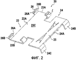
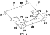
Фиг.2 и фиг.3 - виды в перспективе установочной детали, соответственно показывающие ее внутреннюю поверхность и ее внешнюю поверхность.Figure 2 and figure 3 are perspective views of the installation part, respectively, showing its inner surface and its outer surface.
Фиг.4 - показывает устройство согласно изобретению, когда оно располагается на зажимаемом изделии, где изделие представляет собой трубу, причем устройство показано до его затягивания.4 shows a device according to the invention when it is placed on a clamped product, where the product is a pipe, the device being shown before being tightened.
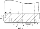
Фиг.5 - вид в разрезе по линии V-V на фиг.5.FIG. 5 is a sectional view taken along line V-V in FIG. 5.
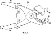
Фиг.6 - вид в перспективе инструмента для установки устройства на такую трубу.6 is a perspective view of a tool for installing the device on such a pipe.
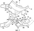
Фиг.7 - показывает взаимодействие указанного инструмента с устройством согласно изобретению перед установкой указанного устройства на трубу.7 - shows the interaction of the specified tool with the device according to the invention before installing the specified device on the pipe.
Фиг.8 - вид, аналогичный фиг.1, для второго варианта воплощения.Fig. 8 is a view similar to Fig. 1 for the second embodiment.
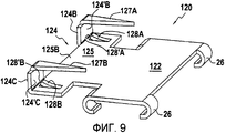
Фиг.9 - вид в перспективе установочной детали, используемой во втором варианте воплощения, показывающий ее внутреннюю поверхность.Fig. 9 is a perspective view of a mounting part used in the second embodiment, showing its inner surface.
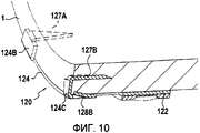
Фиг.10 - частичный вид в перспективе, показывающий в радиальном разрезе взаимодействие указанной установочной детали с трубой.Figure 10 is a partial perspective view showing in radial section the interaction of the specified installation parts with the pipe.
Подробное описаниеDetailed description
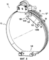
Фиг.1 показывает зажимное устройство согласно изобретению, содержащее зажимное кольцо 10 и две установочные детали, соответственно 20 и 40. Кольцо 10 содержит ленту 12, имеющую две по существу цилиндрические поверхности, а именно внутреннюю поверхность 12А, обращенную к оси А кольца, и внешнюю поверхность 12 В, обращенную в направлении, противоположном направлению, в котором обращена внутренняя поверхность 12А. В данном примере используется кольцо типа «кольцо с тангенциальным винтом». Данное кольцо, таким образом, имеет механизм затягивания, содержащий опору 13, установленную на первом конце 12' ленты. Данная опора поддерживает при повороте винт 14, который идет по касательной относительно цилиндрической поверхности ленты 12 и оси А. Внешняя поверхность 12В ленты имеет рельефные затягивающие элементы 15, которые расположены по меньшей мере в области второго конца 12'' ленты, который вставлен в опору между винтом и внешней поверхностью первого конца 12'. Указанные рельефные затягивающие элементы могут взаимодействовать с резьбой винта, когда винт поворачивается, чтобы переместить второй конец ленты относительно первого конца. Данный тип кольца известен, например, из европейского патента ЕР 0571294 и патента Франции FR 2756356.Figure 1 shows a clamping device according to the invention, comprising a
Каждая из двух установочных деталей 20 и 40 содержит крепежную пластину, соответственно 22 и 42, которая обращена к внутренней поверхности 12А кольца, при этом удерживаясь относительно ленты, и установочный участок соответственно 24 и 44. Установочная деталь 20 описывается ниже со ссылкой на фиг.2 и фиг.3. Необходимо понимать, что эта деталь формируется как единая деталь из полосы материала путем выполнения над ней операций вырезания и сгибания. Установочный участок 24 содержит листовой участок 25, который выполнен за одно целое с крепежной пластиной 22. В данном примере пластина 22 и листовой участок 25 формируются непрерывно друг с другом и формируют плоский пластинчатый элемент.Each of the two mounting
На фиг.1 также можно увидеть, что крепежная пластина 22 удерживается относительно ленты 12 кольца с помощью удерживающих элементов, которые содержат удерживающие лапки 26, которые загнуты назад над краями 13А и 13В ленты. Эти края являются боковыми краями ленты, которые идут перпендикулярно оси А. Указанные лапки формируются на продольных краях пластины, которые проходят перпендикулярно оси А. Можно увидеть, что лапки загнуты назад над краями 13А и 13В, при этом не обжимают эти края, на что указывает зазор j, показанный на фиг.1. Лапки 26 загнуты назад в направлении той же стороны, что и сторона, на которой располагается внешняя поверхность 22А пластины 22, в направлении, противоположном стороне, на которой располагается ее внутренняя поверхность 22В (см. фиг.2 и фиг.3).1, it can also be seen that the mounting
Фиг.1 показывает зажимное устройство в его исходном состоянии, в котором кольцо 10 не затянуто. На фиг.1 можно увидеть, что крепежная пластина 22 или 42 скреплена с (прицеплена к) поверхности 12А ленты. Более точно, поверхность 22А пластины, которая обращена к поверхности 12А ленты и которая таким образом обращена наружу относительно оси А, имеет две зоны сцепления, сформированные на соответствующих концах 23А и 23В пластины, которые соприкасаются с первой поверхностью 12А ленты, тогда как остальная часть внешней поверхности пластины формирует разделительную зону 23С, которая располагается между двумя зонами сцепления и на расстоянии от первой поверхности ленты, на что указывает размерная стрелка D.Figure 1 shows the clamping device in its original state, in which the
Чтобы способствовать сцепляющему эффекту, является предпочтительным, когда зоны сцепления удалены друг от друга, например, путем их формирования на продольных концах 23А и 23В пластины 22, которые идут параллельно оси А. Также возможно предусмотреть, чтобы контакт между поверхностью 22А пластины и поверхностью 12А ленты устанавливался в двух зонах, которые смещены относительно указанных концов 23А и 23В.In order to contribute to the adherence effect, it is preferable when the adherence zones are spaced apart, for example, by forming them on the longitudinal ends 23A and 23B of the
В зонах контакта поверхность 22А пластины формирует угол с поверхностью 12А ленты. Удерживающим лапкам придается такая форма, чтобы контакт между указанными лапками и внешней поверхностью 12В ленты устанавливался на тех краях 26А указанных лапок, которые противоположны концам 23А и 23В и которые таким образом расположены на расстоянии от зон сцепления. В данном примере удерживающие лапки выполнены в непосредственной близости от концов 23А и 23В, так как их края 26В, противоположные вышеуказанным краям 26А, идут непрерывно с указанными концами 23А и 23В. Длина f удерживающих лапок, измеренная в продольном направлении пластины, перпендикулярно оси А, такова, что расстояние между краями 26А удерживающих лапок и зонами сцепления, сформированными концами 23А и 23В пластины, является достаточным. Таким образом на каждом конце создается эффект рычага, способствуя сцеплению.In the contact zones, the
Предпочтительно металлическая полоса, из которой формируется крепежная пластина 22, имеет толщину, которая является достаточно небольшой, чтобы пластина 22 имела возможность деформироваться, когда кольцо затягивается на зажимаемом изделии, чтобы принять, во время затягивания кривизну, которая близка кривизне ленты. В данном примере толщина указанной металлической полосы по существу равна толщине полосы, из которой формируется лента 12. Крепежная пластина 22 представляет собой деталь вытянутой формы, ее длина измеряется перпендикулярно оси А, и эта деталь покрывает угловой сектор а поверхности 12А ленты, причем угол а предпочтительно находится в диапазоне от 5° до 20°.Preferably, the metal strip from which the mounting
В показанном варианте воплощения поверхность ленты 12, напротив которой располагается пластина 22, это внутренняя поверхность 12А ленты. В этом случае, как можно увидеть на чертеже, крепежная пластина 22 формирует хордовый участок, расположенный по существу на хорде дуги, образованный тем участком поверхности 12А ленты, который обращен к указанному хордовому участку. В данном примере пластина является прямолинейной, так что указанный хордовый участок на самом деле аналогичен хорде дуги. Однако в настоящем изобретении подразумевается, что для крепежной пластины будет достаточным иметь по меньше мере один хордовый участок, расположенный по существу на такой хорде. Для установочной пластины является предпочтительным иметь вогнутость, которая показана штриховыми линиями для пластины 40 и обозначается номером позиции 40'. Можно увидеть, что указанная вогнутость обращена в том же направлении, что и вогнутость участка внутренней поверхности ленты, который обращен к пластине. Общая кривизна хордового участка меньше, чем кривизна участка внутренней поверхности ленты. В частности, если пластина имеет цилиндрическую форму, ее радиус кривизны в свободном состоянии больше, чем радиус кривизны ленты, например, приблизительно от 2 до 20 раз больше этого радиуса.In the shown embodiment, the surface of the
Необходимо отметить, что вогнутость пластины может не быть непрерывной, для указанной пластины возможно иметь форму в виде углового сектора с тупым углом при его вершине, предпочтительно более 160°, или даже более 170°.It should be noted that the concavity of the plate may not be continuous, for the specified plate it is possible to have the shape of an angular sector with an obtuse angle at its apex, preferably more than 160 °, or even more than 170 °.
Необходимо отметить, что пластина может быть расположена с внешней стороны ленты кольца. В этом случае пластина может также иметь вогнутую форму, с вогнутостью, обращенной в том же направлении, что и вогнутость указанной ленты, но ее радиус кривизны был бы при этом значительно меньше радиуса кривизны ленты. Удерживающие лапки были бы в этом случае загнуты назад вовнутрь таким образом, чтобы их концы разместились под внутренней поверхностью ленты. Размер t лапок в продольном направлении крепежной пластины предпочтительно был бы увеличен в сравнении с размером, показанного на чертежах, чтобы обеспечить возможность прекращения действия сцепляющего эффекта во время затягивания, под воздействием указанных лапок, деформирующихся из-за реактивных сил от зажимаемого изделия.It should be noted that the plate may be located on the outside of the ring band. In this case, the plate may also have a concave shape, with a concavity facing in the same direction as the concavity of the tape, but its radius of curvature would be much smaller than the radius of curvature of the tape. The holding tabs would then be bent back inward so that their ends are placed under the inner surface of the tape. The size t of the tabs in the longitudinal direction of the mounting plate would preferably be increased in comparison with the size shown in the drawings in order to allow the engagement effect to cease during tightening under the influence of said tabs deforming due to reactive forces from the clamped article.
Однако в данном примере, как указано выше, пластина расположена напротив внутренней поверхности ленты, и удерживающие лапки загнуты назад вовне, т.е. от оси А.However, in this example, as indicated above, the plate is located opposite the inner surface of the tape, and the holding tabs are bent backward outward, i.e. from axis A.
Установочный участок 24 установочной пластины 20 выступает в осевом направлении относительно краев 13А ленты 12.The mounting
Листовой участок 25 по существу параллелен оси А ленты 12. Листовой участок 25 на его краю 24А, дальнем от крепежной пластины 22 и также дальнем от края 13А ленты, имеет два удерживающих выступа 24В и 24С, которые загнуты назад в направлении той же стороны, что и сторона, на которой располагается внутренняя поверхность 25В листового участка. Указанные выступы загнуты назад по существу под прямыми углами относительно листового участка, так что их внутренние поверхности, соответственно 24'В и 24'С, по существу перпендикулярны оси А.The
Указанные внутренние поверхности формируют осевые опорные поверхности. Как можно понять из фиг.4 и фиг.5, которые показывают зажимное устройство согласно изобретению в положении, когда оно размещено вокруг трубы 1, указанные осевые опорные поверхности упираются в осевом направлении в уступ, сформированный свободным концом 1' трубы 1. Они позволяют предотвратить перемещение зажимного устройства относительно трубы в направлении F, указанном на фиг.5.Said inner surfaces form axial bearing surfaces. As can be understood from figure 4 and figure 5, which show the clamping device according to the invention in the position when it is placed around the
Далее, установочный участок 24 имеет два крюка, соответственно 27А и 27В, которые формируют крепежные острые выступы. В данном примере указанные крепежные острые выступы 27А и 27В выступают из-под внутренней поверхности 25 В листового участка 25. Можно увидеть, что они формируются указанным коротким участком. Более точно, крепежные острые выступы вырезаются из листового участка и загибаются относительно него в направлении той же стороны, что и его внутренняя поверхность. На фиг.4 и фиг.5 можно увидеть, что крепежные острые выступы 27А и 27В проникают в трубу 1 и зацепляются с ней подобно зубцу рыболовного крючка. В данном примере указанная труба изготовлена из материала эластомерного типа, в который крепежные острые выступы, которые являются более жесткими, чем этот материал, могут проникать и закрепляться в нем. Заостренные свободные концы 27'A и 27'В крепежных острых выступов делают более легким их проникновение в материал трубы. Как можно увидеть, они загнуты назад в направлении внутренней поверхности 25В листового участка. Это позволяет, при затягивании, каждому крепежному острому выступу, когда они проникают в трубу и зацепляются с ней, принимать форму, которая препятствует им пробить трубу насквозь. Будучи достаточно небольшой, чтобы не мешать проникновению, кривизна свободных концов 27'А и 27'В делает возможным предварительно направить деформацию крепежных острых выступов, которая имеет место во время затягивания, чтобы предотвратить перемещение острых выступов только в радиальном направлении в зацепляемый материал.Further, the
На фиг.4, которая показывает модификацию варианта воплощения на фиг.1, можно увидеть, что установочная пластина и листовой участок по существу имеют форму крыши с двумя скатами, имеющей тупой угол Р при вершине, который немного меньше 180°. Вершина формируется средней линией сгиба, параллельной оси А.In Fig. 4, which shows a modification of the embodiment of Fig. 1, it can be seen that the mounting plate and the sheet section are essentially in the form of a roof with two slopes, having an obtuse angle P at the apex, which is slightly less than 180 °. The top is formed by the middle bend line parallel to the axis A.
Фиг.6 и фиг.7 показывают, в одном варианте воплощения, инструмент, позволяющий установить зажимное устройство на трубе 1. Стандартно эти щипцы 30 имеют две захватные губки 32 и 34, которые могут быть перемещены в направлении друг к другу и друг от друга посредством принудительного поворота ручек 32А и 34А вокруг оси 33 поворота. Захватная губка 34 позволяет разместить устройство согласно изобретению перед затягиванием. С этой целью она имеет внутреннюю поверхность 35А, которая имеет вогнутость, формирующую радиус кривизны, близкий к радиусу кривизны внешней периферии трубы. Перед затягиванием установочная деталь 20 располагается напротив указанной внутренней поверхности 35А, удерживаясь при этом напротив нее с помощью упругого язычка 36. Так как указанная установочная деталь затем устанавливается на ленту кольца (показанную штриховой линией), и зажимное устройство в целом поэтому удерживается захватной губкой 34.6 and 7 show, in one embodiment, a tool for mounting the clamping device on the
В этом случае удерживающие выступы 24В и 24С располагаются вблизи задней стороны 34' захватной губки, под которой понимается сторона, противоположная свободному концу 34'' захватной губки, который является концом, дальним относительно оси 33 поворота.In this case, the holding
Внутренняя поверхность 33А внешней захватной губки (захвата) 32, которая обращена к внутренней стороне 35А захватной губки (захвата) 34, является выгнутой и имеет кривизну, соответствующую кривизне внутренней поверхности 35А. Задняя сторона указанной захватной губки 32 имеет опорную поверхность 32', сформированную, в данном примере, из двух поперечных ребер 33В и 33С на внешних поверхностях, дальних от оси 33. В этом случае конец трубы А может быть помещен напротив внутренней поверхности захватной губки 34 и, более точно, на язычке 36, напротив внутренней поверхности установочной детали. Труба заклинивается в осевом направлении с помощью вышеуказанной опорной поверхности 32', когда захватные губки подаются в направлении друг к другу. Фактически свободный конец 1' трубы 1 упирается во внутренние поверхности 24'В и 24'С удерживающих выступов 24В и 24С. Можно понять, что во время зажима, осуществляемого щипцами путем подачи двух захватных губок в направлении друг к другу, крепежные острые выступы 27А и 27В проникают в материал трубы. После данного зажима, язычок 36, который первой заклинивается между материалом трубы и внутренней поверхностью установочной детали, может быть убран посредством приложения к щипцам осевой тяги.The
В конце данной операции получают узел, формируемый трубой и зажимным устройством согласно изобретению, как показано на фиг.4. Данный узел может быть взят как одно целое и быть присоединен к концевому элементу, на котором труба устанавливается перед тем, как кольцо затягивается, причем затягивание может быть выполнено, используя только инструмент для приведения в движение винта 14 кольца, без необходимости в это же время удерживать указанное кольцо.At the end of this operation, a knot is formed formed by the pipe and the clamping device according to the invention, as shown in FIG. This unit can be taken as a whole and be attached to the end element on which the pipe is installed before the ring is tightened, and the tightening can be performed using only the tool to set the
Установочная деталь 40 не описывалась выше подробно, так как она аналогична во всех отношениях установочной детали 20. В показанном примере удерживающие лапки на обеих деталях могут скользить по ленте 12 кольца. Однако возможно предусмотреть, чтобы удерживающие лапки, расположенные на одном из концов по меньшей мере одной из двух установочных деталей, были обжаты или запрессованы на края ленты, чтобы зафиксировать их относительно ленты.The mounting
В этом случае, поскольку установочные лапки на другом конце не прижаты к ленте, лента и установочная деталь имеют возможность перемещаться относительно друг друга, когда диаметр ленты уменьшается кольцом, которое затягивается. Благодаря фиксации одного из концов установочной детали к ленте, становится возможным избежать любого неожиданного смещения установочной детали относительно ленты, в частности, когда в начале затягивания действие сцепляющего эффекта прекращается из-за деформации пластины. Предотвращение такого смещения позволяет, в частности, удержать кольцо в заданном угловом положении относительно зажимаемого изделия.In this case, since the mounting tabs at the other end are not pressed against the tape, the tape and the mounting piece are able to move relative to each other when the diameter of the tape is reduced by a ring that is tightened. By fixing one of the ends of the mounting part to the tape, it becomes possible to avoid any unexpected displacement of the mounting part relative to the tape, in particular when at the beginning of tightening the adhesion effect ceases due to deformation of the plate. The prevention of such a displacement allows, in particular, to keep the ring in a predetermined angular position relative to the clamped product.
В целом может быть предусмотрено, чтобы один из концов пластины был зафиксирован относительно ленты (с помощью любых подходящих средств, таких как сварка или клепка), тогда как другой конец будет свободен перемещаться, при этом удерживаясь, чтобы сделать возможным начальный сцепляющий эффект.In general, it can be envisaged that one of the ends of the plate is fixed relative to the tape (using any suitable means, such as welding or riveting), while the other end will be free to move while being held in order to make the initial engaging effect possible.
Далее будет описан второй вариант воплощения со ссылкой на фиг.8-10. Кольцо 10 идентично кольцу, показанному на предшествующих чертежах. Установочные детали 120 и 140 аналогичны друг другу, и немного отличаются от деталей, которые были описаны выше. На примере установочной детали 120 можно увидеть, что различия между указанной установочной деталью 120 и вариантом воплощения, показанным на предшествующих чертежах, относятся к установочному участку 124, тогда как крепежная пластина 122 остается неизменной. Отметим, в частности, что она имеет такие же удерживающие лапки 26, что и крепежная пластина 22, показанная на предшествующих чертежах.Next, a second embodiment will be described with reference to FIGS. 8-10.
Как и в первом варианте воплощения, установочный участок 124 содержит листовой участок 125, который выполнен за одно целое с крепежной пластиной 122. Эти два элемента формируются непрерывно друг с другом, и установочная деталь формируется как единая деталь из полосы материала посредством выполнения операций сгибания и вырезания. Как и в предыдущем варианте воплощения, установочный участок 124 имеет удерживающие выступы, соответственно 124В и 124С, которые загнуты назад в направлении той же стороны, что и сторона, на которой располагается внутренняя поверхность 125В листового участка, так что их соответствующие внутренние поверхности 124'В и 124'С формируют осевые опорные поверхности.As in the first embodiment, the mounting
Установочный участок также имеет крепежные острые выступы, соответственно 127А и 127В. Однако, в отличие от первого варианта воплощения, указанные крепежные острые выступы сформированы на свободных краях удерживающих краев, причем эти края загнуты назад под листовым участком 125. В целом во втором варианте воплощения листовой участок имеет по меньшей мере один удерживающий выступ, который имеет край, формирующий крепежный острый выступ. Таким образом крепежные острые выступы идут параллельно оси А, т.е. параллельно листовому участку.The installation section also has fastening sharp protrusions, respectively 127A and 127B. However, unlike the first embodiment, said sharp fastening protrusions are formed on the free edges of the holding edges, these edges being bent back under the
Второй вариант воплощения устройства согласно изобретению может быть размещен на конце 1' трубы 1 путем его перемещения в осевом направлении относительно трубы, так что крепежные острые выступы и 127А и 127В проникают в осевом направлении в материал трубы и зацепляются, подобно зубцу рыболовного крючка, в указанном материале.The second embodiment of the device according to the invention can be placed on the end 1 'of the
Необходимо отметить, что листовой участок 125 имеет два язычка 128А и 128В, которые выступают из-под его внутренней поверхности 125В. Предпочтительно имеется по меньшей мере один язычок этого типа. В данном примере указанные язычки формируются из листового участка, так как они вырезаются из этого участка и приподнимаются от его основания. Они приподнимаются таким образом, что их соответствующие свободные края 128'А и 128'В направлены к вышеуказанным осевым опорным поверхностям 124'В и 124'С. Указанные язычки позволяют удерживать материал трубы на небольшом расстоянии от внутренней поверхности листового участка так, чтобы гарантировать, что крепежные острые выступы 127А и 127В проникнут надлежащим образом в свободные края указанной трубы. Благодаря направлению, в котором идут их свободные концы, язычки предотвращают любое смещение установочной детали относительно трубы в направлении, противоположном направлению F, показанному на фиг.5. Указанные язычки могут быть упругодеформируемыми, так чтобы действовать подобно пружинам, путем их возвращения в пределы толщины листового участка во время затягивания.It should be noted that the
Claims (17)
Applications Claiming Priority (2)
| Application Number | Priority Date | Filing Date | Title |
|---|---|---|---|
| FR0756510 | 2007-07-16 | ||
| FR0756510A FR2919039B1 (en) | 2007-07-16 | 2007-07-16 | CLAMPING DEVICE WITH CLAMPING NECK AND POSITIONING PIECE |
Publications (2)
| Publication Number | Publication Date |
|---|---|
| RU2008129029A RU2008129029A (en) | 2010-01-20 |
| RU2477209C2 true RU2477209C2 (en) | 2013-03-10 |
Family
ID=38698861
Family Applications (1)
| Application Number | Title | Priority Date | Filing Date |
|---|---|---|---|
| RU2008129029/02A RU2477209C2 (en) | 2007-07-16 | 2008-07-15 | Clamper with clamping ring and location part |
Country Status (9)
| Country | Link |
|---|---|
| US (1) | US7802821B2 (en) |
| EP (1) | EP2017518B1 (en) |
| KR (1) | KR101570669B1 (en) |
| CN (1) | CN101349299A (en) |
| AT (1) | ATE481594T1 (en) |
| BR (1) | BRPI0802443B1 (en) |
| DE (1) | DE602008002496D1 (en) |
| FR (1) | FR2919039B1 (en) |
| RU (1) | RU2477209C2 (en) |
Families Citing this family (22)
| Publication number | Priority date | Publication date | Assignee | Title |
|---|---|---|---|---|
| US20060170215A1 (en) * | 2002-11-29 | 2006-08-03 | Martin Cousineau | Hose clamp |
| KR100867746B1 (en) * | 2008-02-15 | 2008-11-10 | 안국인더스트리 주식회사 | Hores binding clamp |
| DE102008013207A1 (en) | 2008-03-07 | 2009-09-24 | Veritas Ag | Clamp fixation for a hose end |
| DE102008046893A1 (en) * | 2008-09-11 | 2010-03-25 | Veritas Ag | clamp fitting |
| FR2959294B1 (en) * | 2010-04-21 | 2012-03-30 | Delphi Tech Inc | SEAL NECKLACE |
| FR2967230B1 (en) * | 2010-11-05 | 2013-08-30 | Caillau Ets | ARTICULATED TIGHTENING NECKLACE |
| JP5827033B2 (en) * | 2011-05-20 | 2015-12-02 | 本田技研工業株式会社 | Clamp device for connection |
| CN102343984B (en) * | 2011-07-08 | 2014-01-01 | 凯迈(洛阳)测控有限公司 | Locking mechanism in rudder deflection angle testing device |
| FR3004505B1 (en) * | 2013-04-11 | 2015-05-08 | Caillau Ets | CLAMPING DEVICE FOR THE SEALED COUPLING OF SMOOTH TUBES |
| CN105627002A (en) * | 2014-10-29 | 2016-06-01 | 安徽中鼎胶管制品有限公司 | Worm wheel-worm hoop and rubber pipe assembly and installation method thereof |
| KR200477672Y1 (en) * | 2015-02-12 | 2015-07-08 | 주식회사 화승알앤에이 | Clamp Guide and Clamp Assembly Including The Same |
| US10584817B2 (en) * | 2015-12-28 | 2020-03-10 | Ideal Clamp Products, Inc. | Hose clamp with retaining bracket |
| WO2018149485A1 (en) * | 2017-02-14 | 2018-08-23 | Oetiker Schweiz Ag | Fixing element for a clamping clip |
| US10627029B2 (en) * | 2017-08-11 | 2020-04-21 | Tread Enterprises Ltd. | Hose clamp with integral claws |
| CN108978790A (en) * | 2018-06-08 | 2018-12-11 | 苏州海马消防设备制造有限公司 | A kind of fire water box with fixed function |
| CN109148126A (en) * | 2018-10-26 | 2019-01-04 | 国网江苏省电力有限公司扬州市江都区供电分公司 | A kind of transformer pile head snap connectors |
| CA3072832A1 (en) | 2019-02-19 | 2020-08-19 | Duravent, Inc. | Conduit locking system for an appliance |
| KR20210136137A (en) * | 2019-03-25 | 2021-11-16 | 아이디얼 클램프 프로덕츠, 인크. | Locator systems and methods for hose clamps |
| EP3953631A4 (en) | 2019-04-11 | 2022-03-23 | Kale Baglanti Teknolojileri Sanayi Ve Ticaret Anonim Sirketi | A hose clamp |
| CN110842665A (en) * | 2019-11-26 | 2020-02-28 | 杨培土 | Aluminum alloy wheel hub equipment of polishing |
| EP4113183A4 (en) * | 2020-02-28 | 2023-12-06 | Nippon Telegraph And Telephone Corporation | Optical fiber cable gripping device |
| CN112356493B (en) * | 2020-10-23 | 2022-03-29 | 一重集团大连工程技术有限公司 | Clamping device for carbon electrode extruder |
Citations (5)
| Publication number | Priority date | Publication date | Assignee | Title |
|---|---|---|---|---|
| US3407488A (en) * | 1966-07-28 | 1968-10-29 | Gen Electric | Methods for altering the configuration of electrically conductive turns of inductivedevices |
| FR2680405A1 (en) * | 1991-08-16 | 1993-02-19 | Rasmussen Gmbh | HOSE CLAMP FOR HOSES, WITH AUTOMATIC TIGHTENING AND SIMPLIFIED MOUNTING. |
| EP0571294A1 (en) * | 1992-05-22 | 1993-11-24 | Etablissements CAILLAU | Pipe clamp provided with a screw |
| FR2756356A1 (en) * | 1996-11-25 | 1998-05-29 | Caillau Ets | CLAMP FOR ELASTIC HOUSING |
| RU15381U1 (en) * | 2000-07-12 | 2000-10-10 | Соколов Олег Игоревич | Worm Clamp |
Family Cites Families (13)
| Publication number | Priority date | Publication date | Assignee | Title |
|---|---|---|---|---|
| US1389282A (en) * | 1920-06-07 | 1921-08-30 | Harry C Yingling | Coupling device |
| US3365218A (en) * | 1965-01-25 | 1968-01-23 | Richard T. Denyes | Hose and clamp preassembly |
| US3389442A (en) * | 1966-05-13 | 1968-06-25 | Wittek Mfg Co | Hose clamp with load distributing member |
| US3407448A (en) * | 1967-03-03 | 1968-10-29 | Wittek Mfg Company | Hose clamp with hose-attaching means |
| US3477106A (en) * | 1968-03-22 | 1969-11-11 | Wittek Mfg Co | Hose clamp with hose attaching means |
| US4453289A (en) * | 1980-04-04 | 1984-06-12 | Dayco Corporation | Hose clamp structure and hose construction employing same |
| DE4005631A1 (en) * | 1990-02-22 | 1991-09-05 | Rasmussen Gmbh | HOSE CLAMP |
| US5499430A (en) * | 1994-08-10 | 1996-03-19 | Strazar; Andrew A. | Hose clamp with supplemental holding fingers |
| FR2758604B1 (en) * | 1997-01-21 | 1999-04-02 | Lionel Calmettes | TIGHTENING COLLAR |
| GB2326920A (en) * | 1997-07-01 | 1999-01-06 | Rasmussen Gmbh | Clamp for clamping a hose on a pipe portion |
| FR2833065B1 (en) * | 2001-12-05 | 2004-09-03 | Caillau Ets | CLAMPING SYSTEM FOR THE SEALED CONNECTION OF TWO TUBES HAVING SUPPORT SURFACES |
| US6824169B2 (en) * | 2002-11-14 | 2004-11-30 | Dayco Products, Llc | Hose and clamp assembly, clamp subassembly and method |
| US6942253B2 (en) * | 2003-04-18 | 2005-09-13 | Epicor Industries, Inc. | Locator tab and associated hose clamp |
-
2007
- 2007-07-16 FR FR0756510A patent/FR2919039B1/en not_active Expired - Fee Related
-
2008
- 2008-07-14 KR KR1020080068315A patent/KR101570669B1/en active IP Right Grant
- 2008-07-15 RU RU2008129029/02A patent/RU2477209C2/en active
- 2008-07-15 EP EP08160379A patent/EP2017518B1/en active Active
- 2008-07-15 BR BRPI0802443-0A patent/BRPI0802443B1/en active IP Right Grant
- 2008-07-15 AT AT08160379T patent/ATE481594T1/en not_active IP Right Cessation
- 2008-07-15 DE DE602008002496T patent/DE602008002496D1/en active Active
- 2008-07-16 US US12/174,482 patent/US7802821B2/en active Active
- 2008-07-16 CN CNA2008101320105A patent/CN101349299A/en active Pending
Patent Citations (5)
| Publication number | Priority date | Publication date | Assignee | Title |
|---|---|---|---|---|
| US3407488A (en) * | 1966-07-28 | 1968-10-29 | Gen Electric | Methods for altering the configuration of electrically conductive turns of inductivedevices |
| FR2680405A1 (en) * | 1991-08-16 | 1993-02-19 | Rasmussen Gmbh | HOSE CLAMP FOR HOSES, WITH AUTOMATIC TIGHTENING AND SIMPLIFIED MOUNTING. |
| EP0571294A1 (en) * | 1992-05-22 | 1993-11-24 | Etablissements CAILLAU | Pipe clamp provided with a screw |
| FR2756356A1 (en) * | 1996-11-25 | 1998-05-29 | Caillau Ets | CLAMP FOR ELASTIC HOUSING |
| RU15381U1 (en) * | 2000-07-12 | 2000-10-10 | Соколов Олег Игоревич | Worm Clamp |
Also Published As
| Publication number | Publication date |
|---|---|
| KR20090008133A (en) | 2009-01-21 |
| BRPI0802443B1 (en) | 2019-05-07 |
| ATE481594T1 (en) | 2010-10-15 |
| US20090019673A1 (en) | 2009-01-22 |
| DE602008002496D1 (en) | 2010-10-28 |
| BRPI0802443A2 (en) | 2010-04-06 |
| FR2919039B1 (en) | 2012-12-28 |
| RU2008129029A (en) | 2010-01-20 |
| KR101570669B1 (en) | 2015-11-27 |
| US7802821B2 (en) | 2010-09-28 |
| FR2919039A1 (en) | 2009-01-23 |
| CN101349299A (en) | 2009-01-21 |
| EP2017518A1 (en) | 2009-01-21 |
| EP2017518B1 (en) | 2010-09-15 |
Similar Documents
| Publication | Publication Date | Title |
|---|---|---|
| RU2477209C2 (en) | Clamper with clamping ring and location part | |
| US11705703B2 (en) | Adjustable P-clamp with multiple mounting options | |
| US4742600A (en) | Band clamp | |
| US8127406B2 (en) | Hose clamp | |
| GB2326920A (en) | Clamp for clamping a hose on a pipe portion | |
| US20130212842A1 (en) | Hinged Clamping Collar | |
| JP6920387B2 (en) | Adjustable P-clamp with multiple installation options | |
| US6216992B1 (en) | Mounting device for securing a sink to a countertop and method of using same | |
| AU2008357891B2 (en) | Hose clamps | |
| HUE031124T2 (en) | Profile clamp with seal element | |
| JP2003097517A (en) | Pipe fastener, especially pipe connector | |
| US10962156B2 (en) | Hose clamp | |
| GB2127480A (en) | Band clamp | |
| US8464987B1 (en) | Adjustable conduit clamp | |
| US20200408334A1 (en) | Clamp assembly | |
| JPS63190912A (en) | Lug-less clamp structure | |
| JP3415642B2 (en) | Clamp structure | |
| EP2613062B1 (en) | Shielding and insulation fastener | |
| CA3040555C (en) | Clamping clip | |
| WO2010092702A1 (en) | Hose clamp | |
| US4343451A (en) | Sensor retaining system | |
| US20220196057A1 (en) | Connecting device | |
| EP0010559B1 (en) | Pipe and cable clamps | |
| JP2007028766A (en) | Corrugated tube attaching jig | |
| JP2004325974A (en) | Clamp for closure of optical cable and method for manufacturing the same |