RU2476335C2 - Working machine with stepless transmission with output controlled subject to engine load - Google Patents
Working machine with stepless transmission with output controlled subject to engine load Download PDFInfo
- Publication number
- RU2476335C2 RU2476335C2 RU2008143111/06A RU2008143111A RU2476335C2 RU 2476335 C2 RU2476335 C2 RU 2476335C2 RU 2008143111/06 A RU2008143111/06 A RU 2008143111/06A RU 2008143111 A RU2008143111 A RU 2008143111A RU 2476335 C2 RU2476335 C2 RU 2476335C2
- Authority
- RU
- Russia
- Prior art keywords
- internal combustion
- load
- combustion engine
- specified
- working machine
- Prior art date
Links
Images
Classifications
-
- F—MECHANICAL ENGINEERING; LIGHTING; HEATING; WEAPONS; BLASTING
- F16—ENGINEERING ELEMENTS AND UNITS; GENERAL MEASURES FOR PRODUCING AND MAINTAINING EFFECTIVE FUNCTIONING OF MACHINES OR INSTALLATIONS; THERMAL INSULATION IN GENERAL
- F16H—GEARING
- F16H15/00—Gearings for conveying rotary motion with variable gear ratio, or for reversing rotary motion, by friction between rotary members
- F16H15/02—Gearings for conveying rotary motion with variable gear ratio, or for reversing rotary motion, by friction between rotary members without members having orbital motion
- F16H15/04—Gearings providing a continuous range of gear ratios
-
- B—PERFORMING OPERATIONS; TRANSPORTING
- B60—VEHICLES IN GENERAL
- B60W—CONJOINT CONTROL OF VEHICLE SUB-UNITS OF DIFFERENT TYPE OR DIFFERENT FUNCTION; CONTROL SYSTEMS SPECIALLY ADAPTED FOR HYBRID VEHICLES; ROAD VEHICLE DRIVE CONTROL SYSTEMS FOR PURPOSES NOT RELATED TO THE CONTROL OF A PARTICULAR SUB-UNIT
- B60W10/00—Conjoint control of vehicle sub-units of different type or different function
- B60W10/04—Conjoint control of vehicle sub-units of different type or different function including control of propulsion units
-
- B—PERFORMING OPERATIONS; TRANSPORTING
- B60—VEHICLES IN GENERAL
- B60K—ARRANGEMENT OR MOUNTING OF PROPULSION UNITS OR OF TRANSMISSIONS IN VEHICLES; ARRANGEMENT OR MOUNTING OF PLURAL DIVERSE PRIME-MOVERS IN VEHICLES; AUXILIARY DRIVES FOR VEHICLES; INSTRUMENTATION OR DASHBOARDS FOR VEHICLES; ARRANGEMENTS IN CONNECTION WITH COOLING, AIR INTAKE, GAS EXHAUST OR FUEL SUPPLY OF PROPULSION UNITS IN VEHICLES
- B60K17/00—Arrangement or mounting of transmissions in vehicles
- B60K17/04—Arrangement or mounting of transmissions in vehicles characterised by arrangement, location, or kind of gearing
- B60K17/06—Arrangement or mounting of transmissions in vehicles characterised by arrangement, location, or kind of gearing of change-speed gearing
-
- B—PERFORMING OPERATIONS; TRANSPORTING
- B60—VEHICLES IN GENERAL
- B60W—CONJOINT CONTROL OF VEHICLE SUB-UNITS OF DIFFERENT TYPE OR DIFFERENT FUNCTION; CONTROL SYSTEMS SPECIALLY ADAPTED FOR HYBRID VEHICLES; ROAD VEHICLE DRIVE CONTROL SYSTEMS FOR PURPOSES NOT RELATED TO THE CONTROL OF A PARTICULAR SUB-UNIT
- B60W10/00—Conjoint control of vehicle sub-units of different type or different function
- B60W10/10—Conjoint control of vehicle sub-units of different type or different function including control of change-speed gearings
- B60W10/101—Infinitely variable gearings
- B60W10/103—Infinitely variable gearings of fluid type
-
- B—PERFORMING OPERATIONS; TRANSPORTING
- B60—VEHICLES IN GENERAL
- B60W—CONJOINT CONTROL OF VEHICLE SUB-UNITS OF DIFFERENT TYPE OR DIFFERENT FUNCTION; CONTROL SYSTEMS SPECIALLY ADAPTED FOR HYBRID VEHICLES; ROAD VEHICLE DRIVE CONTROL SYSTEMS FOR PURPOSES NOT RELATED TO THE CONTROL OF A PARTICULAR SUB-UNIT
- B60W30/00—Purposes of road vehicle drive control systems not related to the control of a particular sub-unit, e.g. of systems using conjoint control of vehicle sub-units, or advanced driver assistance systems for ensuring comfort, stability and safety or drive control systems for propelling or retarding the vehicle
- B60W30/18—Propelling the vehicle
- B60W30/188—Controlling power parameters of the driveline, e.g. determining the required power
- B60W30/1884—Avoiding stall or overspeed of the engine
-
- B—PERFORMING OPERATIONS; TRANSPORTING
- B60—VEHICLES IN GENERAL
- B60W—CONJOINT CONTROL OF VEHICLE SUB-UNITS OF DIFFERENT TYPE OR DIFFERENT FUNCTION; CONTROL SYSTEMS SPECIALLY ADAPTED FOR HYBRID VEHICLES; ROAD VEHICLE DRIVE CONTROL SYSTEMS FOR PURPOSES NOT RELATED TO THE CONTROL OF A PARTICULAR SUB-UNIT
- B60W30/00—Purposes of road vehicle drive control systems not related to the control of a particular sub-unit, e.g. of systems using conjoint control of vehicle sub-units, or advanced driver assistance systems for ensuring comfort, stability and safety or drive control systems for propelling or retarding the vehicle
- B60W30/18—Propelling the vehicle
- B60W30/188—Controlling power parameters of the driveline, e.g. determining the required power
- B60W30/1886—Controlling power supply to auxiliary devices
-
- B—PERFORMING OPERATIONS; TRANSPORTING
- B60—VEHICLES IN GENERAL
- B60W—CONJOINT CONTROL OF VEHICLE SUB-UNITS OF DIFFERENT TYPE OR DIFFERENT FUNCTION; CONTROL SYSTEMS SPECIALLY ADAPTED FOR HYBRID VEHICLES; ROAD VEHICLE DRIVE CONTROL SYSTEMS FOR PURPOSES NOT RELATED TO THE CONTROL OF A PARTICULAR SUB-UNIT
- B60W2510/00—Input parameters relating to a particular sub-units
- B60W2510/06—Combustion engines, Gas turbines
- B60W2510/0638—Engine speed
-
- B—PERFORMING OPERATIONS; TRANSPORTING
- B60—VEHICLES IN GENERAL
- B60W—CONJOINT CONTROL OF VEHICLE SUB-UNITS OF DIFFERENT TYPE OR DIFFERENT FUNCTION; CONTROL SYSTEMS SPECIALLY ADAPTED FOR HYBRID VEHICLES; ROAD VEHICLE DRIVE CONTROL SYSTEMS FOR PURPOSES NOT RELATED TO THE CONTROL OF A PARTICULAR SUB-UNIT
- B60W2510/00—Input parameters relating to a particular sub-units
- B60W2510/06—Combustion engines, Gas turbines
- B60W2510/0657—Engine torque
-
- B—PERFORMING OPERATIONS; TRANSPORTING
- B60—VEHICLES IN GENERAL
- B60W—CONJOINT CONTROL OF VEHICLE SUB-UNITS OF DIFFERENT TYPE OR DIFFERENT FUNCTION; CONTROL SYSTEMS SPECIALLY ADAPTED FOR HYBRID VEHICLES; ROAD VEHICLE DRIVE CONTROL SYSTEMS FOR PURPOSES NOT RELATED TO THE CONTROL OF A PARTICULAR SUB-UNIT
- B60W2510/00—Input parameters relating to a particular sub-units
- B60W2510/20—Steering systems
-
- B—PERFORMING OPERATIONS; TRANSPORTING
- B60—VEHICLES IN GENERAL
- B60W—CONJOINT CONTROL OF VEHICLE SUB-UNITS OF DIFFERENT TYPE OR DIFFERENT FUNCTION; CONTROL SYSTEMS SPECIALLY ADAPTED FOR HYBRID VEHICLES; ROAD VEHICLE DRIVE CONTROL SYSTEMS FOR PURPOSES NOT RELATED TO THE CONTROL OF A PARTICULAR SUB-UNIT
- B60W2540/00—Input parameters relating to occupants
- B60W2540/18—Steering angle
-
- B—PERFORMING OPERATIONS; TRANSPORTING
- B60—VEHICLES IN GENERAL
- B60W—CONJOINT CONTROL OF VEHICLE SUB-UNITS OF DIFFERENT TYPE OR DIFFERENT FUNCTION; CONTROL SYSTEMS SPECIALLY ADAPTED FOR HYBRID VEHICLES; ROAD VEHICLE DRIVE CONTROL SYSTEMS FOR PURPOSES NOT RELATED TO THE CONTROL OF A PARTICULAR SUB-UNIT
- B60W2710/00—Output or target parameters relating to a particular sub-units
- B60W2710/10—Change speed gearings
- B60W2710/105—Output torque
-
- B—PERFORMING OPERATIONS; TRANSPORTING
- B60—VEHICLES IN GENERAL
- B60Y—INDEXING SCHEME RELATING TO ASPECTS CROSS-CUTTING VEHICLE TECHNOLOGY
- B60Y2200/00—Type of vehicle
- B60Y2200/40—Special vehicles
- B60Y2200/41—Construction vehicles, e.g. graders, excavators
Abstract
Description
Область техники, к которой относится изобретениеFIELD OF THE INVENTION
Настоящее изобретение относится к рабочим машинам, и, в частности, - к рабочим машинам, содержащим двигатель внутреннего сгорания, спаренный с бесступенчатой коробкой передач.The present invention relates to working machines, and, in particular, to working machines containing an internal combustion engine, paired with a continuously variable transmission.
Уровень техникиState of the art
Рабочая машина, такая как строительная рабочая машина, сельскохозяйственная рабочая машина или лесная рабочая машина, обычно включает в себя пусковой двигатель в виде двигателя внутреннего сгорания (IC). Двигатель внутреннего сгорания (IC) может быть либо в виде двигателя с воспламенением от сжатия (т.е. дизельным двигателем) или двигателем с принудительным зажиганием (т.е. карбюраторным двигателем). Для большей части тяжелых рабочих машин пусковым двигателем является дизельный двигатель, имеющий лучшие характеристики зацепления, понижения напряжения и крутящего момента для объединенных рабочих операций.A work machine, such as a construction work machine, agricultural work machine, or forestry work machine, typically includes a starting engine in the form of an internal combustion engine (IC). An internal combustion engine (IC) may be either a compression ignition engine (i.e., a diesel engine) or a positive ignition engine (i.e., a carburetor engine). For most heavy duty machines, the starting engine is the diesel engine, which has the best gearing, undervoltage and torque characteristics for integrated work operations.
Срабатывание двигателя внутреннего сгорания при ступенчатой нагрузке в переходном режиме после ударной нагрузки является характеристикой, на которую больше всего влияет объем двигателя, металлические изделия двигателя (например, имеет ли двигатель стандартный турбокомпрессор, турбокомпрессор с перепускным клапаном или регулируемой геометрии и т. д.) и стратегия программного обеспечения для запуска воздушного и топливного приводов (например, рециркуляция выхлопных газов, турбокомпрессор с турбиной регулируемой геометрии (VGT), конструкция топливного инжектора и т.д.) с учетом требований законодательства о выделениях в окружающую среду (например, видимый дым, азотные окислы (NOx) и т.д.), шум или вибрации. Ударная нагрузка может быть результатом нагрузки на трансмиссию (например, прицепное сельскохозяйственное орудие за машиной) или внешней нагрузкой (например, вспомогательная гидравлическая нагрузка такая как фронтальный погрузчик, навесное оборудование обратной лопаты (экскаватора) и т.д.)The operation of an internal combustion engine during a step load in transition after an impact load is a characteristic that is most affected by engine size, engine metal products (for example, does the engine have a standard turbocharger, a turbocharger with an overflow valve or an adjustable geometry, etc.) and software strategy for starting air and fuel drives (e.g. exhaust gas recirculation, variable geometry turbocharger (VGT), design fuel injector, etc.), taking into account the requirements of the legislation on emissions into the environment (for example, visible smoke, nitrogen oxides (NO x ), etc.), noise or vibration. The shock load may be the result of a load on the transmission (for example, a trailed agricultural implement behind the machine) or an external load (for example, auxiliary hydraulic load such as a front loader, attachments for a backhoe (excavator), etc.)
Системы двигателя в целом реагируют линейным образом во время переходного режима при приложении не устоявшейся нагрузки. Сначала, нагрузка приложена к валу двигателя внутреннего сгорания IC. Скорость двигателя внутреннего сгорания IC снижается, когда нагрузка увеличивается. Падение скорости двигателя зависит от того, является ли регулятор изохронным или имеется падение скорости. Воздушный поток увеличивается, чтобы снабдить двигатель внутреннего сгорания IC дополнительным воздухом, изменяя воздушные приводы. Задержка во времени необходима, чтобы достичь контрольной точки нового воздушного потока. Количество впрыска топлива, который происходит почти немедленно, увеличивается с учетом предела дымности выхлопных газов и максимально допустимого количества топлива. Затем двигатель возвращается к контрольной точке скорости двигателя. Показателями, связанными с реагированием двигателя на ступенчатую нагрузку во время переходного режима после ударной нагрузки, являются падение скорости и время возвращения к контрольной точке двигателя.Engine systems generally respond linearly during transient conditions when an unstable load is applied. First, a load is applied to the shaft of the IC internal combustion engine. The speed of the internal combustion engine IC decreases when the load increases. A drop in engine speed depends on whether the controller is isochronous or if there is a drop in speed. The airflow is increased to provide the IC internal combustion engine with additional air, changing the air drives. A time delay is needed to reach the milestone of the new airflow. The amount of fuel injection that occurs almost immediately increases taking into account the exhaust smoke limit and the maximum allowable amount of fuel. The engine then returns to the engine speed reference point. The indicators associated with the response of the engine to a step load during the transition mode after the shock load are the speed drop and the time of return to the engine reference point.
Двигатель внутреннего сгорания IC может быть спарен с бесступенчатой коробкой передач (IVT), которая создает непрерывную изменяемую скорость на выходе от 0 до максимального значения в плавном виде. Бесступенчатая коробка передач IVT обычно содержит гидростатические составляющие и механические зубчатые передачи. Гидростатические составляющие переводят мощность вала вращения в гидравлический поток, и наоборот. Поток мощности через бесступенчатую коробку передач IVT может быть только через гидростатические узлы, только через механические узлы или только через сочетание и тех, и других в зависимости от конструкции и скорости на выходе.The IC internal combustion engine can be paired with a continuously variable transmission (IVT), which creates a continuously variable output speed from 0 to the maximum value in a smooth form. An IVT continuously variable transmission typically contains hydrostatic components and mechanical gears. Hydrostatic components translate the power of the rotation shaft into the hydraulic flow, and vice versa. The power flow through the IVT continuously variable transmission can be only through hydrostatic units, only through mechanical units, or only through a combination of both, depending on the design and output speed.
Рабочая машина, содержащая двигатель внутреннего сгорания IC, спаренный с бесступенчатой коробкой передач IVT, может выявлять проблемы, которые могут быть преодолены двумя путями: первый - внезапные нагрузки, приложенные к прицепной или гидравлической функциям машины, вызывают снижение скорости двигателя. Реагирование, - чтобы изменить передаточное число бесступенчатой коробки передач IVT для сокращения уже сниженной нагрузки двигателя, происходит медленнее, чем необходимо, чтобы предотвратить значительное падение скорости двигателя и иногда потерю скорости. Второй, когда внешняя нагрузка приложена к двигателю внутреннего сгорания IC, такая как при наполнении ковша фронтального погрузчика на машине с бесступенчатой коробкой передач IVT, водитель может управлять скоростью машины в значительно большей степени, нежели это возможно с двигателем внутреннего сгорания IC. При этих условиях выходной крутящий момент бесступенчатой коробки передач IVT и скорость могут приводить к пробуксовыванию колес и другим нежелательным признакам. Подобным образом, если внешняя нагрузка от другого внешнего действия, такого как гидравлическое действие, передана к коробке передач, то внешняя нагрузка в совокупности с пропускной способностью коробки передач может привести двигатель в состояние перегрузки.A working machine containing an IC internal combustion engine coupled to an IVT continuously variable transmission can identify problems that can be overcome in two ways: first, sudden loads applied to the trailer or hydraulic functions of the machine cause a decrease in engine speed. The response - to change the gear ratio of a continuously variable IVT gearbox to reduce an already reduced engine load, is slower than necessary to prevent a significant drop in engine speed and sometimes loss of speed. Second, when an external load is applied to the IC internal combustion engine, such as when filling the front loader bucket with an IVT gearbox, the driver can control the speed of the machine to a much greater extent than is possible with the IC internal combustion engine. Under these conditions, the output torque of the continuously variable IVT gearbox and speed can lead to wheel slipping and other undesirable symptoms. Similarly, if an external load from another external action, such as a hydraulic action, is transferred to the gearbox, then the external load, combined with the transmission capacity of the gearbox, can cause the engine to overload.
В данной области техники необходимы рабочая машина и соответствующий способ работы, позволяющий регулировать мощность бесступенчатой коробки передач IVT таким образом, чтобы избежать режима перегрузки двигателя внутреннего сгорания IC.In the art, a working machine and an appropriate mode of operation are needed to control the power of an IVT continuously variable transmission in such a way as to avoid overloading the IC internal combustion engine.
Раскрытие изобретенияDisclosure of invention
Изобретение в одном виде касается рабочей машины, включая двигатель внутреннего сгорания IC и бесступенчатую коробку передач IVT, спаренную с двигателем внутреннего сгорания IC. По меньшей мере, один сенсор подает выходной сигнал, представляющий собой значение нагрузки в реальном времени на двигателе внутреннего сгорания IC. По меньшей мере, выполнен один электрический контур обработки данных для контроля мощности бесступенчатой коробки передач IVT, в зависимости от значения пороговой нагрузки для двигателя внутреннего сгорания IC и значения нагрузки в реальном времени для двигателя внутреннего сгорания IC.The invention in one form relates to a working machine, including an IC internal combustion engine and an IVT continuously variable transmission paired with an IC internal combustion engine. At least one sensor delivers an output signal representing the real-time load value of the internal combustion engine IC. At least one electrical data processing circuit is provided to monitor the power of the continuously variable IVT gearbox, depending on the threshold load value for the internal combustion engine IC and the real-time load value for the internal combustion engine IC.
В другом виде изобретение касается способа работы рабочей машины, включающей в себя двигатель внутреннего сгорания IC, спаренный с бесступенчатой коробкой передач IVT. Этот способ включает в себя этапы: установление значения пороговой нагрузки, соответствующей максимально разрешенной нагрузке на двигатель внутреннего сгорания IC; определение значения нагрузки в реальном времени, связанной с двигателем внутреннего сгорания IC; сравнение значения нагрузки в реальном времени со значением пороговой нагрузки; и контроль мощности бесступенчатой коробки передач IVT, в зависимости от этапа сравнения.In another form, the invention relates to a method of operating a work machine, including an IC internal combustion engine, coupled to an IVT continuously variable transmission. This method includes the steps of: setting the threshold load value corresponding to the maximum permitted load on the internal combustion engine IC; determining the value of the load in real time associated with the internal combustion engine IC; comparing the value of the load in real time with the value of the threshold load; and IVT continuously variable transmission power control, depending on the stage of comparison.
Краткое описание чертежейBrief Description of the Drawings
Фиг.1 - схематичное изображение варианта осуществления рабочей машины согласно настоящему изобретению; и наFigure 1 is a schematic illustration of an embodiment of a working machine according to the present invention; and on
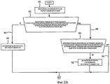
Фиг.2А и 2В - блок-схема варианта осуществления способа работы рабочей машины согласно настоящему изобретению.2A and 2B are a flowchart of an embodiment of a method of operating a working machine according to the present invention.
Подробное описание изобретенияDETAILED DESCRIPTION OF THE INVENTION
Согласно фиг.1 показано схематичное изображение варианта осуществления рабочей машины 10 согласно настоящему изобретению. Предполагается, что рабочей машиной 10 является строительная рабочая машина, такая как фронтальный погрузчик фирмы Джон Дир, но рабочей машиной может быть и другой вид рабочей машины, такой как сельскохозяйственная, лесная, горная или промышленная рабочая машина.1, a schematic illustration of an embodiment of a working machine 10 according to the present invention is shown. It is assumed that the working machine 10 is a construction working machine, such as a John Deere front loader, but the working machine may also be another type of working machine, such as an agricultural, forestry, mining or industrial working machine.
Рабочая машина 10 включает в себя двигатель внутреннего сгорания 12, который спарен с бесступенчатой коробкой передач 14, обычно через выходной коленчатый вал 16 двигателя внутреннего сгорания 12. Предполагается, что двигателем внутреннего сгорания 12 является дизельный двигатель в показанном варианте осуществления изобретения, но им может быть также и карбюраторный двигатель, пропановый двигатель и т.д. Двигатель внутреннего сгорания 12 имеет размеры и конструкцию согласно описанию.The working machine 10 includes an internal combustion engine 12, which is paired with a continuously variable gearbox 14, usually through an output crankshaft 16 of the internal combustion engine 12. It is assumed that the internal combustion engine 12 is a diesel engine in the illustrated embodiment, but it may be also carburetor engine, propane engine, etc. The internal combustion engine 12 has dimensions and design as described.
Бесступенчатая коробка передач 14 может быть выполнена соответствующей конструкции, и поэтому не описана здесь подробно. Бесступенчатая коробка передач 14 имеет выход, который соединен, по меньшей мере, с одним другим нижним прицепным составляющим элементом 18, который, в свою очередь, соединен со множеством приводных колес 20, одно из которых показано на фиг.1. Конечно, необходимо понимать, что в случае рабочей машины гусеничного типа, прицепной составной элемент 18 может быть соединен с гусеницей.The continuously variable gearbox 14 may be configured accordingly, and therefore is not described in detail here. The continuously variable gearbox 14 has an output that is connected to at least one other lower trailed component 18, which, in turn, is connected to a plurality of drive wheels 20, one of which is shown in FIG. Of course, it must be understood that in the case of a caterpillar-type working machine, the towed component 18 can be connected to the caterpillar.
Бесступенчатая коробка передач 14 также подает выходную мощность к одной или более внешним нагрузкам 22, которые, в свою очередь, таким образом, оказывают дополнительную нагрузку на двигатель внутреннего сгорания 12. Внешние нагрузки 22 обычно предстают в виде гидравлических нагрузок, таких как фронтальный погрузчик, стрела крана экскаватора, разгрузочный зерновой шнек, двигатель пилы для рубки деревьев и т.д. Полная нагрузка на двигатель внутреннего сгорания 12, таким образом, является функцией и тяговых нагрузок, и внешних гидравлических нагрузок.The continuously variable gearbox 14 also delivers output power to one or more external loads 22, which, in turn, thus exert additional load on the internal combustion engine 12. External loads 22 are usually in the form of hydraulic loads, such as a front loader, boom excavator crane, unloading grain auger, saw engine for tree felling, etc. The total load on the internal combustion engine 12 is thus a function of both the traction loads and the external hydraulic loads.
Блок 24 управления двигателем (ECU) электронным путем контролирует работу двигателя внутреннего сгорания 12 и соединен с множеством сенсоров (не показаны конкретно), связанных с работой двигателя внутреннего сгорания 12. Например, блок 24 управления двигателем (ECU) может быть соединен с сенсором, показывающим контрольные параметры двигателя, такие как скорость воздушного потока внутри одного или нескольких впускных трубопроводов, скорость двигателя, расход топлива и/или регулировку момента зажигания в двигателе, скорость рециркуляции выхлопных газов (ERG), положение лопаток турбокомпрессора и т.д. Кроме того, блок 24 управления двигателем может получать выходные сигналы от блока 28 управления машиной, представляющего параметры управления машиной, введенные водителем, такие как регулируемая сухопутная скорость (указанная положением рычагов переключения передач и рычагов управления дроссельной заслонкой и/или гидростатическим рычагом) или регулируемое направление рабочей машины 10 (указанное угловым направлением рулевого колеса).The engine control unit (ECU) 24 electronically monitors the operation of the internal combustion engine 12 and is connected to a plurality of sensors (not shown specifically) related to the operation of the internal combustion engine 12. For example, the engine control unit (ECU) 24 may be connected to a sensor showing engine control parameters, such as air flow rate inside one or more intake pipes, engine speed, fuel consumption and / or ignition timing in the engine, exhaust recirculation rate s gases (ERG), turbocharger blade position, etc. In addition, the engine control unit 24 may receive output signals from the machine control unit 28 representing the machine control parameters entered by the driver, such as an adjustable ground speed (indicated by the position of the gear levers and throttle and / or hydrostatic levers) or an adjustable direction working machine 10 (indicated by the angular direction of the steering wheel).
Подобным образом, блок 26 управления коробкой передач (TCU) электронным путем контролирует работу бесступенчатой коробки передач IVT 14 и соединен с множеством сенсоров, связанных с работой бесступенчатой коробки передач IVT 14. Блок 24 управления двигателем ECU и блок 26 управления коробкой передач TCU спарены вместе с помощью шинной структуры, обеспечивающей двухсторонний поток данных, такой как шина 30 участка сетевого адаптера (CAN).Similarly, the transmission control unit (TCU) 26 electronically monitors the operation of the continuously variable transmission IVT 14 and is connected to a plurality of sensors associated with the operation of the continuously variable transmission IVT 14. The ECU engine control unit 24 and the TCU transmission control unit 26 are paired with using a bus structure providing two-way data flow, such as a bus 30 of a portion of a network adapter (CAN).
Хотя различные электронные составляющие, такие как блок 24 управления двигателем ECU, блок 26 управления коробкой передач TCU и блок 28 управления машиной VCU показаны спаренными вместе с использованием проволочного соединения, необходимо также понимать, что беспроволочные соединения могут быть использованы для некоторых применений.Although various electronic components such as the ECU engine control unit 24, the TCU gearbox control unit 26, and the VCU machine control unit 28 are shown paired together using a wire connection, it should also be understood that wireless connections can be used for some applications.
Согласно фиг.2А и 2В, вариант осуществления способа работы рабочей машины 10 согласно настоящему изобретению будет описан более подробно. В блоке 40 установлено определенное пользователем значение пороговой нагрузки, такое как введено через коммутационную панель, соединенную с блоком управления машиной VCU 28, и сохранено в памяти.2A and 2B, an embodiment of a method of operating a working machine 10 according to the present invention will be described in more detail. In
Одна возможность установки значения пороговой нагрузки заключается в совпадении этой нагрузки с максимальным значением крутящего момента/нагрузки на кривой крутящего момента для данного двигателя внутреннего сгорания. Например, для данного двигателя внутреннего сгорания принято использовать заранее определенную кривую крутящего момента с крутящим моментом (нагрузкой), являющейся функцией скорости двигателя. Кривая крутящего момента может быть сохранена в памяти или динамически определена с помощью заданной математической функции. Такие кривые крутящего момента хорошо известны в данной области техники, и поэтому не показаны в данном описании в целях краткости. Кривая крутящего момента, используемая в работе, определяет максимальный выходной крутящий момент на заданной скорости двигателя. Таким образом, возможно число максимальных выходных крутящих моментов, каждый из которых соответствует различной рабочей скорости двигателя внутреннего сгорания 12. Крутящий момент или нагрузка является вращательным усилием коленчатого вала двигателя, т.е. выходной мощностью. Скорость двигателя обычно определяют положением дроссельной заслонки либо электронной, либо механической. Для соответствующего крутящего момента двигателя блок 24 управления двигателем (ECU) контролирует работу одного или более контрольных параметров двигателя для достижения желаемого выходного крутящего момента, который соответствует или меньше максимального крутящего момента для этой рабочей скорости. Например, блок 24 управления двигателем (ECU) может контролировать рециркуляцию выхлопных газов (ERG), регулируемую в ERG системе (также как соотношение разбавления с воздухом), контролируемый элемент в турбокомпрессоре регулируемой геометрии (VGT), время впрыска топлива и/или давление топлива. Таким образом, можно, чтобы установленное значение пороговой нагрузки соответствовало значению максимальной нагрузки на кривой крутящего момента при заданной рабочей скорости, или десятичной степени значения максимальной нагрузки.One possibility of setting the threshold load value is to match this load with the maximum torque / load on the torque curve for a given internal combustion engine. For example, for a given internal combustion engine, it is customary to use a predetermined torque curve with a torque (load) that is a function of engine speed. The torque curve can be stored in memory or dynamically determined using a given mathematical function. Such torque curves are well known in the art and therefore are not shown in this description for brevity. The torque curve used in the work determines the maximum output torque at a given engine speed. Thus, the number of maximum output torques is possible, each of which corresponds to a different operating speed of the internal combustion engine 12. The torque or load is the rotational force of the engine crankshaft, i.e. output power. Engine speed is usually determined by the position of the throttle valve, either electronic or mechanical. For the appropriate engine torque, the engine control unit (ECU) monitors the operation of one or more engine control parameters to achieve the desired output torque that corresponds to or less than the maximum torque for this operating speed. For example, engine control unit (ECU) 24 can control exhaust gas recirculation (ERG), adjustable in an ERG system (also like dilution to air ratio), controlled element in a variable geometry turbocharger (VGT), fuel injection time and / or fuel pressure. Thus, it is possible that the set threshold load value corresponds to the maximum load on the torque curve at a given operating speed, or a decimal degree of the maximum load value.
В блоке 42 принятия решения установлено число критериев для определения, должен ли быть понижен выходящий крутящий момент бесступенчатой коробки передач IVT 14. Во-первых, если значение нагрузки в реальном времени на двигатель внутреннего сгорания больше, чем значение максимальной нагрузки, введенное в блок 40, тогда существует указание, что выходной крутящий момент бесступенчатой коробки передач IVT 14 должен быть понижен. Значение нагрузки в реальном времени может быть считано или выведено с помощью некоторого числа методик, таких как считывание скорости потока топлива в реальном времени в двигателе внутреннего сгорания 12. Другими факторами, принимаемыми во внимание в блоке принятия решения 42, являются технические требования переключения передач, технические требования скорости машины и другие разнообразные технические требования.In
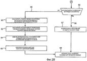
Если в блоке 42 принятия решения принято решение активировать понижение крутящего момента (линия 44), тогда просто активируют понижение крутящего момента (блок 46). С другой стороны, если понижение крутящего момента не активировано (линия 48), принимается решение дезактивировать функцию понижения крутящего момента (блок 50 принятия решения). Другими словами, даже если принято решение не активировать понижение крутящего момента в блоке 42 принятия решения, понижение крутящего момента может фактически находиться уже в активированном состоянии от предшествующего логического контура. Блок 50 принятия решения снова проверяет рабочие параметры, включая технические требования переключения передач, технические требования скорости машины и другие разнообразные технические требования для определения, нужно ли дезактивировать понижение крутящего момента. Если это так, тогда понижение крутящего момента просто дезактивируют (блок 52), - другими словами, контроль проходит по линии 54.If, in
В блоке 55 принятия решений выполняется проверка, действительно ли понижение крутящего момента активировано или дезактивировано. Если понижение крутящего момента дезактивировано (линия 56), тогда бесступенчатая коробка передач 14 не выходит за рамки номинала, и 100% тягового усилия приложено к выходу бесступенчатой коробки передач 14 (блок 57). С другой стороны, если активировано понижение крутящего момента (линия 58), тогда коэффициент пересчета понижения крутящего момента рассчитывается на основе разницы между значением нагрузки в реальном времени и значением пороговой нагрузки (блоки 60 и 62). Любые определенные пользователем пределы по коэффициенту пересчета понижения крутящего момента учтены в блоке 64, данные контура обратной связи соответственно корректируются в блоке 66, и логическая схема заканчивается в блоке 68 коэффициентом пересчета понижения крутящего момента.At
Описав предпочтительные варианты осуществления изобретения, очевидно, что различные изменения могут быть выполнены, не выходя за объем изобретения, который определен прилагаемой формулой изобретения.Having described the preferred embodiments of the invention, it is apparent that various changes can be made without departing from the scope of the invention as defined by the appended claims.
Claims (17)
двигатель внутреннего сгорания (IC);
бесступенчатую коробку передач (IVT), спаренную с двигателем внутреннего сгорания (IC);
по меньшей мере, один сенсор, производящий выходной сигнал, представляющий собой значение нагрузки в реальном времени на указанном двигателе внутреннего сгорания (IC); и
по меньшей мере, один электрический контур обработки данных для управления мощностью бесступенчатой коробки передач (IVT), в зависимости от значения пороговой нагрузки для указанного двигателя внутреннего сгорания IC и указанного значения нагрузки в реальном времени для указанного двигателя внутреннего сгорания IC.1. A working machine containing:
internal combustion engine (IC);
continuously variable transmission (IVT), paired with an internal combustion engine (IC);
at least one sensor producing an output signal representing the value of the load in real time on the specified internal combustion engine (IC); and
at least one electrical data processing circuit for controlling a continuously variable transmission (IVT) power, depending on a threshold load value for said internal combustion engine IC and said real-time load value for said internal combustion engine IC.
задание значения пороговой нагрузки, соответствующей максимально разрешенной нагрузке на двигатель внутреннего сгорания IC;
определение значения нагрузки в реальном времени, связанной с двигателем внутреннего сгорания IC;
сравнение указанной нагрузки в реальном времени с указанным значением пороговой нагрузки; и
управление мощностью бесступенчатой коробки передач IVT, в зависимости от указанного этапа сравнения.11. A method of controlling a working machine comprising an IC internal combustion engine coupled to an IVT continuously variable transmission, comprising the steps of:
setting the threshold load value corresponding to the maximum allowed load on the IC internal combustion engine;
determining the value of the load in real time associated with the internal combustion engine IC;
comparing the specified load in real time with the specified value of the threshold load; and
IVT continuously variable transmission power control, depending on the specified comparison step.
выработку выходного сигнала от указанного блока управления двигателем (ECU) к указанному блоку управления коробкой передач TCU, представляющему собой указанное значение нагрузки в реальном времени; и
управление указанной мощностью указанной бесступенчатой коробки передач IVT с использованием указанного блока управления коробкой передач TCU, в зависимости от указанного этапа сравнения.12. The method of controlling a working machine according to claim 11, wherein said at least one electrical data processing circuit includes an engine control unit (ECU) associated with said internal combustion engine IC, and a transmission control unit TCU associated with the specified continuously variable transmission IVT, and includes the following steps:
generating an output signal from the specified engine control unit (ECU) to the specified TCU gearbox control unit, representing the indicated load value in real time; and
controlling said power of said continuously variable IVT gearbox using said TCU gearbox control unit, depending on said comparison step.
Applications Claiming Priority (2)
| Application Number | Priority Date | Filing Date | Title |
|---|---|---|---|
| US11/930,669 US8457848B2 (en) | 2007-10-31 | 2007-10-31 | Work machine with IVT output automatically adjusted dependent upon engine load |
| US11/930,669 | 2007-10-31 |
Publications (2)
| Publication Number | Publication Date |
|---|---|
| RU2008143111A RU2008143111A (en) | 2010-05-10 |
| RU2476335C2 true RU2476335C2 (en) | 2013-02-27 |
Family
ID=40229963
Family Applications (1)
| Application Number | Title | Priority Date | Filing Date |
|---|---|---|---|
| RU2008143111/06A RU2476335C2 (en) | 2007-10-31 | 2008-10-30 | Working machine with stepless transmission with output controlled subject to engine load |
Country Status (9)
| Country | Link |
|---|---|
| US (1) | US8457848B2 (en) |
| EP (1) | EP2055543B1 (en) |
| JP (1) | JP5420880B2 (en) |
| KR (1) | KR20090045017A (en) |
| CN (1) | CN101424338A (en) |
| AT (1) | ATE542723T1 (en) |
| CA (1) | CA2640154C (en) |
| MX (1) | MX2008013740A (en) |
| RU (1) | RU2476335C2 (en) |
Cited By (1)
| Publication number | Priority date | Publication date | Assignee | Title |
|---|---|---|---|---|
| RU2675179C2 (en) * | 2013-09-30 | 2018-12-17 | ФПТ ИНДАСТРИАЛ С.п.А. | System for preventing mechanical damage of internal combustion engine due to inefficient lubrication of engine itself |
Families Citing this family (10)
| Publication number | Priority date | Publication date | Assignee | Title |
|---|---|---|---|---|
| US8060284B2 (en) * | 2007-10-31 | 2011-11-15 | Deere & Company | Work machine with torque limiting control for an infinitely variable transmission |
| US8843282B2 (en) * | 2011-11-02 | 2014-09-23 | Caterpillar Inc. | Machine, control system and method for hovering an implement |
| KR102115036B1 (en) | 2013-10-24 | 2020-05-26 | 두산인프라코어 주식회사 | Communication stabilization system and the method, When the controller software updating |
| US9619948B2 (en) | 2015-08-06 | 2017-04-11 | Caterpillar Inc. | System and method for monitoring an earth-moving operation of a machine |
| WO2018098568A1 (en) * | 2016-12-01 | 2018-06-07 | Transmission Cvtcorp Inc. | Cvt ratio control with respect to the actual engine torque of the prime mover |
| US11066081B2 (en) * | 2018-05-01 | 2021-07-20 | Ford Global Technologies, Llc | Methods and apparatus to modify vehicle function based on loading conditions |
| CN114127086B (en) * | 2019-07-25 | 2023-10-20 | 四川海思科制药有限公司 | Deuterated peptide amide compound and preparation method and medical application thereof |
| CN114127085A (en) * | 2019-07-25 | 2022-03-01 | 四川海思科制药有限公司 | Peptide amide salt, preparation method and medical application thereof |
| CN112810601B (en) * | 2020-12-29 | 2022-03-01 | 北京农业智能装备技术研究中心 | Method and system for regulating and controlling traveling speed of unmanned agricultural machine |
| CN112814069A (en) * | 2020-12-30 | 2021-05-18 | 天津工程机械研究院有限公司 | Wheel loader and control method |
Citations (7)
| Publication number | Priority date | Publication date | Assignee | Title |
|---|---|---|---|---|
| US4523892A (en) * | 1984-05-14 | 1985-06-18 | Caterpillar Tractor Co. | Hydrostatic vehicle control |
| US5967756A (en) * | 1997-07-01 | 1999-10-19 | Caterpillar Inc. | Power management control system for a hydraulic work machine |
| RU2142567C1 (en) * | 1994-04-12 | 1999-12-10 | Юнайтид Текнолоджиз Копэрейшн | Automatic engine speed governing system and method (options) |
| US6405844B1 (en) * | 1999-09-10 | 2002-06-18 | Komatsu Ltd. | Working vehicle |
| US20050071067A1 (en) * | 2003-09-30 | 2005-03-31 | Caterpillar Inc. | Predictive load management system |
| RU2284926C2 (en) * | 2003-09-22 | 2006-10-10 | Федеральное государственное унитарное предприятие "Государственный научно-исследовательский тракторный институт "НАТИ" | Method of automatic adaptive control of infinitely-variable transmission of traction machines and vehicles |
| RU2288110C2 (en) * | 2003-09-22 | 2006-11-27 | Федеральное государственное унитарное предприятие "Государственный научно-исследовательский тракторный институт "НАТИ" | Adaptive control device for stepless transmission of traction and transport vehicles |
Family Cites Families (28)
| Publication number | Priority date | Publication date | Assignee | Title |
|---|---|---|---|---|
| DE2934270A1 (en) * | 1979-08-24 | 1981-03-26 | Zahnradfabrik Friedrichshafen Ag, 7990 Friedrichshafen | AUTOMATIC CONTROL DEVICE OF A CONTINUOUSLY ADJUSTABLE TRANSMISSION GEAR, DRIVED BY AN INTERNAL COMBUSTION ENGINE, IN PARTICULAR FOR VEHICLES |
| FR2480000A1 (en) * | 1980-04-03 | 1981-10-09 | Renault | ELECTRONIC CONTROL FOR AUTOMATIC TRANSMISSION OF MOTOR VEHICLE USING A MICROCALCULATOR |
| JPS57146944A (en) * | 1981-03-04 | 1982-09-10 | Toyota Motor Corp | Speed change controller of automatic speed changer |
| AT378615B (en) * | 1984-02-01 | 1985-09-10 | Steyr Daimler Puch Ag | AUXILIARY DEVICE FOR OBTAINING OPTIMAL VALUES FOR COMMERCIAL VEHICLES |
| US4930078A (en) * | 1984-07-23 | 1990-05-29 | Eaton Corporation | Semi-automatic mechanical transmission control and control method |
| US4669334A (en) * | 1984-09-14 | 1987-06-02 | Nippon Seiko Kabushiki Kaisha | Transmission control apparatus for infinitely variable transmission |
| JPS61119860A (en) * | 1984-11-16 | 1986-06-07 | Fuji Heavy Ind Ltd | Electronic control device for continuously variable transmission |
| US4740898A (en) * | 1986-07-17 | 1988-04-26 | Deere & Company | Automatic engine/transmission control system |
| AU1244388A (en) * | 1987-02-04 | 1988-08-24 | Kabushiki Kaisha Komatsu Seisakusho | Automatic speed change method for dump truck for construction machine |
| US5129288A (en) * | 1989-09-29 | 1992-07-14 | Mazda Motor Corporation | Transmission control system for automatic transmission |
| US5152191A (en) * | 1989-12-28 | 1992-10-06 | Fuji Jukogyo Kabushiki Kaisha | Control system of a continuously variable transmission for a four-wheel motor vehicle |
| DE4120546C2 (en) * | 1991-06-21 | 1995-04-13 | Porsche Ag | Device for controlling a continuously variable motor vehicle transmission |
| DE4430447C2 (en) | 1994-08-27 | 1997-10-16 | Deere & Co | Method and control device for controlling the drive train of a work vehicle |
| US6665601B1 (en) * | 1998-12-22 | 2003-12-16 | Case Corporation | Communications system for managing messages across a vehicle data bus |
| US6249727B1 (en) * | 1999-05-19 | 2001-06-19 | Caterpillar Inc. | Method and apparatus for customizing and limiting operation of machine subsystems |
| US6188944B1 (en) * | 1999-06-01 | 2001-02-13 | Ford Motor Company | Torque control strategy for engines with continuously variable transmission |
| US6249733B1 (en) * | 1999-06-02 | 2001-06-19 | Caterpillar Inc. | Automatic engine retarder and transmission control in off highway earth moving equipment |
| US6601442B1 (en) * | 1999-09-20 | 2003-08-05 | Cummins, Inc. | Duty cycle monitoring system for an engine |
| US6247378B1 (en) | 2000-01-06 | 2001-06-19 | Deere & Company | Operator control device for an infinitely variable transmission |
| GB2362127B (en) * | 2000-05-13 | 2002-05-22 | Ford New Holland Nv | Method and apparatus for controlling a tractor/baler combination |
| EP1172248A3 (en) * | 2000-07-12 | 2006-10-04 | Deere & Company | Work vehicle with operator selected load control |
| JP3680746B2 (en) * | 2001-03-09 | 2005-08-10 | 日産自動車株式会社 | Control device for infinitely variable continuously variable transmission |
| US6842689B2 (en) * | 2002-05-15 | 2005-01-11 | Caterpillar Inc | System for dynamically controlling power provided by an engine |
| JP4386890B2 (en) * | 2003-05-07 | 2009-12-16 | 株式会社小松製作所 | Work machine equipped with prime mover control device |
| US6950735B2 (en) | 2003-06-09 | 2005-09-27 | Deere & Company | Load anticipating engine/transmission control system |
| JP2007177661A (en) * | 2005-12-27 | 2007-07-12 | Jtekt Corp | Drive control device for vehicle |
| JP4901269B2 (en) * | 2006-03-31 | 2012-03-21 | 株式会社エクォス・リサーチ | Toroidal continuously variable transmission |
| US8070651B2 (en) * | 2007-12-07 | 2011-12-06 | Deere & Company | Work machine coast and brake control with an infinitely variable transmission |
-
2007
- 2007-10-31 US US11/930,669 patent/US8457848B2/en active Active
-
2008
- 2008-10-01 CA CA2640154A patent/CA2640154C/en active Active
- 2008-10-10 CN CNA2008101675475A patent/CN101424338A/en active Pending
- 2008-10-23 KR KR1020080104202A patent/KR20090045017A/en not_active Application Discontinuation
- 2008-10-27 MX MX2008013740A patent/MX2008013740A/en active IP Right Grant
- 2008-10-30 AT AT08167917T patent/ATE542723T1/en active
- 2008-10-30 RU RU2008143111/06A patent/RU2476335C2/en active
- 2008-10-30 EP EP08167917A patent/EP2055543B1/en active Active
- 2008-10-31 JP JP2008280958A patent/JP5420880B2/en not_active Expired - Fee Related
Patent Citations (7)
| Publication number | Priority date | Publication date | Assignee | Title |
|---|---|---|---|---|
| US4523892A (en) * | 1984-05-14 | 1985-06-18 | Caterpillar Tractor Co. | Hydrostatic vehicle control |
| RU2142567C1 (en) * | 1994-04-12 | 1999-12-10 | Юнайтид Текнолоджиз Копэрейшн | Automatic engine speed governing system and method (options) |
| US5967756A (en) * | 1997-07-01 | 1999-10-19 | Caterpillar Inc. | Power management control system for a hydraulic work machine |
| US6405844B1 (en) * | 1999-09-10 | 2002-06-18 | Komatsu Ltd. | Working vehicle |
| RU2284926C2 (en) * | 2003-09-22 | 2006-10-10 | Федеральное государственное унитарное предприятие "Государственный научно-исследовательский тракторный институт "НАТИ" | Method of automatic adaptive control of infinitely-variable transmission of traction machines and vehicles |
| RU2288110C2 (en) * | 2003-09-22 | 2006-11-27 | Федеральное государственное унитарное предприятие "Государственный научно-исследовательский тракторный институт "НАТИ" | Adaptive control device for stepless transmission of traction and transport vehicles |
| US20050071067A1 (en) * | 2003-09-30 | 2005-03-31 | Caterpillar Inc. | Predictive load management system |
Cited By (1)
| Publication number | Priority date | Publication date | Assignee | Title |
|---|---|---|---|---|
| RU2675179C2 (en) * | 2013-09-30 | 2018-12-17 | ФПТ ИНДАСТРИАЛ С.п.А. | System for preventing mechanical damage of internal combustion engine due to inefficient lubrication of engine itself |
Also Published As
| Publication number | Publication date |
|---|---|
| ATE542723T1 (en) | 2012-02-15 |
| EP2055543B1 (en) | 2012-01-25 |
| JP2009133482A (en) | 2009-06-18 |
| MX2008013740A (en) | 2010-05-14 |
| CA2640154A1 (en) | 2009-04-30 |
| RU2008143111A (en) | 2010-05-10 |
| JP5420880B2 (en) | 2014-02-19 |
| CA2640154C (en) | 2016-03-29 |
| US8457848B2 (en) | 2013-06-04 |
| EP2055543A2 (en) | 2009-05-06 |
| CN101424338A (en) | 2009-05-06 |
| KR20090045017A (en) | 2009-05-07 |
| EP2055543A3 (en) | 2010-09-08 |
| US20090112413A1 (en) | 2009-04-30 |
Similar Documents
| Publication | Publication Date | Title |
|---|---|---|
| RU2476335C2 (en) | Working machine with stepless transmission with output controlled subject to engine load | |
| CA2641121C (en) | Work machine with torque limiting control for an infinitely variable transmission | |
| CA2645970C (en) | Work machine with power limit control using an infinitely varible transmission | |
| JP5419416B2 (en) | Work machine with torque limiting control for continuously variable transmission mechanism | |
| US8070651B2 (en) | Work machine coast and brake control with an infinitely variable transmission | |
| EP1936154B1 (en) | Method of operating an internal combustion engine and control system for operation of an internal combustion engine |