RU2472468C2 - System for lens delivery - Google Patents
System for lens delivery Download PDFInfo
- Publication number
- RU2472468C2 RU2472468C2 RU2010121933/14A RU2010121933A RU2472468C2 RU 2472468 C2 RU2472468 C2 RU 2472468C2 RU 2010121933/14 A RU2010121933/14 A RU 2010121933/14A RU 2010121933 A RU2010121933 A RU 2010121933A RU 2472468 C2 RU2472468 C2 RU 2472468C2
- Authority
- RU
- Russia
- Prior art keywords
- plunger
- outer shaft
- cartridge
- groove
- ring
- Prior art date
Links
Images

Classifications
-
- A—HUMAN NECESSITIES
- A61—MEDICAL OR VETERINARY SCIENCE; HYGIENE
- A61F—FILTERS IMPLANTABLE INTO BLOOD VESSELS; PROSTHESES; DEVICES PROVIDING PATENCY TO, OR PREVENTING COLLAPSING OF, TUBULAR STRUCTURES OF THE BODY, e.g. STENTS; ORTHOPAEDIC, NURSING OR CONTRACEPTIVE DEVICES; FOMENTATION; TREATMENT OR PROTECTION OF EYES OR EARS; BANDAGES, DRESSINGS OR ABSORBENT PADS; FIRST-AID KITS
- A61F9/00—Methods or devices for treatment of the eyes; Devices for putting-in contact lenses; Devices to correct squinting; Apparatus to guide the blind; Protective devices for the eyes, carried on the body or in the hand
- A61F9/007—Methods or devices for eye surgery
-
- A—HUMAN NECESSITIES
- A61—MEDICAL OR VETERINARY SCIENCE; HYGIENE
- A61B—DIAGNOSIS; SURGERY; IDENTIFICATION
- A61B17/00—Surgical instruments, devices or methods, e.g. tourniquets
-
- A—HUMAN NECESSITIES
- A61—MEDICAL OR VETERINARY SCIENCE; HYGIENE
- A61F—FILTERS IMPLANTABLE INTO BLOOD VESSELS; PROSTHESES; DEVICES PROVIDING PATENCY TO, OR PREVENTING COLLAPSING OF, TUBULAR STRUCTURES OF THE BODY, e.g. STENTS; ORTHOPAEDIC, NURSING OR CONTRACEPTIVE DEVICES; FOMENTATION; TREATMENT OR PROTECTION OF EYES OR EARS; BANDAGES, DRESSINGS OR ABSORBENT PADS; FIRST-AID KITS
- A61F2/00—Filters implantable into blood vessels; Prostheses, i.e. artificial substitutes or replacements for parts of the body; Appliances for connecting them with the body; Devices providing patency to, or preventing collapsing of, tubular structures of the body, e.g. stents
- A61F2/02—Prostheses implantable into the body
- A61F2/14—Eye parts, e.g. lenses, corneal implants; Implanting instruments specially adapted therefor; Artificial eyes
- A61F2/16—Intraocular lenses
- A61F2/1662—Instruments for inserting intraocular lenses into the eye
- A61F2/1667—Instruments for inserting intraocular lenses into the eye with rotatable plungers
-
- A—HUMAN NECESSITIES
- A61—MEDICAL OR VETERINARY SCIENCE; HYGIENE
- A61F—FILTERS IMPLANTABLE INTO BLOOD VESSELS; PROSTHESES; DEVICES PROVIDING PATENCY TO, OR PREVENTING COLLAPSING OF, TUBULAR STRUCTURES OF THE BODY, e.g. STENTS; ORTHOPAEDIC, NURSING OR CONTRACEPTIVE DEVICES; FOMENTATION; TREATMENT OR PROTECTION OF EYES OR EARS; BANDAGES, DRESSINGS OR ABSORBENT PADS; FIRST-AID KITS
- A61F2/00—Filters implantable into blood vessels; Prostheses, i.e. artificial substitutes or replacements for parts of the body; Appliances for connecting them with the body; Devices providing patency to, or preventing collapsing of, tubular structures of the body, e.g. stents
- A61F2/02—Prostheses implantable into the body
- A61F2/14—Eye parts, e.g. lenses, corneal implants; Implanting instruments specially adapted therefor; Artificial eyes
- A61F2/16—Intraocular lenses
- A61F2/1662—Instruments for inserting intraocular lenses into the eye
- A61F2/167—Instruments for inserting intraocular lenses into the eye with pushable plungers
-
- A—HUMAN NECESSITIES
- A61—MEDICAL OR VETERINARY SCIENCE; HYGIENE
- A61F—FILTERS IMPLANTABLE INTO BLOOD VESSELS; PROSTHESES; DEVICES PROVIDING PATENCY TO, OR PREVENTING COLLAPSING OF, TUBULAR STRUCTURES OF THE BODY, e.g. STENTS; ORTHOPAEDIC, NURSING OR CONTRACEPTIVE DEVICES; FOMENTATION; TREATMENT OR PROTECTION OF EYES OR EARS; BANDAGES, DRESSINGS OR ABSORBENT PADS; FIRST-AID KITS
- A61F9/00—Methods or devices for treatment of the eyes; Devices for putting-in contact lenses; Devices to correct squinting; Apparatus to guide the blind; Protective devices for the eyes, carried on the body or in the hand
- A61F9/0061—Devices for putting-in contact lenses
-
- A—HUMAN NECESSITIES
- A61—MEDICAL OR VETERINARY SCIENCE; HYGIENE
- A61F—FILTERS IMPLANTABLE INTO BLOOD VESSELS; PROSTHESES; DEVICES PROVIDING PATENCY TO, OR PREVENTING COLLAPSING OF, TUBULAR STRUCTURES OF THE BODY, e.g. STENTS; ORTHOPAEDIC, NURSING OR CONTRACEPTIVE DEVICES; FOMENTATION; TREATMENT OR PROTECTION OF EYES OR EARS; BANDAGES, DRESSINGS OR ABSORBENT PADS; FIRST-AID KITS
- A61F9/00—Methods or devices for treatment of the eyes; Devices for putting-in contact lenses; Devices to correct squinting; Apparatus to guide the blind; Protective devices for the eyes, carried on the body or in the hand
- A61F9/007—Methods or devices for eye surgery
- A61F9/00736—Instruments for removal of intra-ocular material or intra-ocular injection, e.g. cataract instruments
-
- A—HUMAN NECESSITIES
- A61—MEDICAL OR VETERINARY SCIENCE; HYGIENE
- A61M—DEVICES FOR INTRODUCING MEDIA INTO, OR ONTO, THE BODY; DEVICES FOR TRANSDUCING BODY MEDIA OR FOR TAKING MEDIA FROM THE BODY; DEVICES FOR PRODUCING OR ENDING SLEEP OR STUPOR
- A61M5/00—Devices for bringing media into the body in a subcutaneous, intra-vascular or intramuscular way; Accessories therefor, e.g. filling or cleaning devices, arm-rests
- A61M5/178—Syringes
- A61M5/31—Details
- A61M5/315—Pistons; Piston-rods; Guiding, blocking or restricting the movement of the rod or piston; Appliances on the rod for facilitating dosing ; Dosing mechanisms
- A61M5/31501—Means for blocking or restricting the movement of the rod or piston
- A61M5/31505—Integral with the syringe barrel, i.e. connected to the barrel so as to make up a single complete piece or unit
- A61M2005/31506—Integral with the syringe barrel, i.e. connected to the barrel so as to make up a single complete piece or unit formed as a single piece, e.g. moulded
Abstract
Description
Данное изобретение касается интраокулярных линз (ИОЛ), а более конкретно устройств, используемых для введения ИОЛ в глаз.The present invention relates to intraocular lenses (IOLs), and more particularly, devices used to introduce IOLs into the eye.
УРОВЕНЬ ТЕХНИКИBACKGROUND
Человеческий глаз, в простейшем своем представлении, обеспечивает зрительное восприятие путем пропускания и преломления света через прозрачный наружный участок, называемый роговицей, и далее фокусирования зрительного образа посредством хрусталика на сетчатке в задней части глаза. Качество сфокусированного образа зависит от многих факторов, в том числе от размера, формы и длины глаза, а также от формы и прозрачности роговицы и хрусталика.The human eye, in its simplest representation, provides visual perception by transmitting and refracting light through a transparent outer area called the cornea, and then focusing the visual image through the lens on the retina in the back of the eye. The quality of the focused image depends on many factors, including the size, shape and length of the eye, as well as the shape and transparency of the cornea and lens.
Если травма, возраст или болезнь приводят к тому, что хрусталик становится менее прозрачным, зрение ухудшается, поскольку на сетчатку поступает меньше света. Этот дефект хрусталика глаза в медицине известен как катаракта. Лечение при таком заболевании заключается в удалении хрусталика хирургическим путем и имплантации искусственного хрусталика или ИОЛ.If an injury, age, or illness causes the lens to become less clear, vision deteriorates as less light enters the retina. This defect of the lens of the eye is known in medicine as cataracts. Treatment for such a disease involves surgical removal of the lens and implantation of an artificial lens or IOL.
В то время как первые интраокулярные линзы выполнялись из жесткого пластика, такого как полиметилметакрилат (ПММА), теперь все большую популярность приобретают мягкие, складывающиеся интраокулярные линзы, выполненные из силикона, мягких акриловых материалов и гидрогелей, поскольку такие мягкие линзы можно складывать или сворачивать и вводить через меньший разрез. Используется несколько способов сворачивания или складывания линз. Один из распространенных способов заключается в использовании инжекторного картриджа, в котором линзы складываются и который обеспечивает просвет сравнительно малого диаметра, через него линзу можно протолкнуть в глаз, обычно с использованием плунжера с мягким наконечником. Наиболее широко используемая конструкция инжекторного картриджа представлена в патенте США №5681102 (Bartell), которая включает в себя составной картридж с шарнирным соединением в продольном направлении. Схожие конструкции представлены в патентах США №№5494484 и 5499987 (Feingold), а также 5616148 и 5620450 (Eagles и др.). В попытках обойти формулу изобретения по патенту США №5681102 исследовались некоторые цельные картриджи, см., например, патент США №5275604 (Rheinish и др.) и 5653715 (Reich и др.).While the first intraocular lenses were made of hard plastic, such as polymethylmethacrylate (PMMA), soft, folding intraocular lenses made of silicone, soft acrylic materials and hydrogels are becoming increasingly popular, since such soft lenses can be folded or rolled up and inserted through a smaller incision. Several methods of folding or folding lenses are used. One common method is to use an injection cartridge in which the lenses are folded and which provides a relatively small diameter clearance, through which the lens can be pushed into the eye, usually using a plunger with a soft tip. The most widely used injector cartridge design is presented in US Pat. No. 5,681,102 (Bartell), which includes an integral cartridge with a swivel joint in the longitudinal direction. Similar designs are presented in US patent No. 5494484 and 5499987 (Feingold), as well as 5616148 and 5620450 (Eagles and others). In an attempt to circumvent the claims of US Pat. No. 5,681,102, several solid cartridges have been investigated, see, for example, US Pat. No. 5,275,604 (Rheinish et al.) And 5653715 (Reich et al.).
Ручные блоки, используемые для картриджей предшествующего уровня техники, обычно проталкивают линзы через картридж с помощью плунжера. Плунжер либо непосредственно проталкивается пользователем (по принципу шприца), либо снабжен резьбой и продвигается с помощью вращающейся ручки. Тип используемого ручного блока обычно определяется предпочтениями хирурга, но было бы предпочтительно, чтобы ручной блок содержал механизм, позволяющий осуществлять оба вида перемещения.Hand blocks used in prior art cartridges typically push lenses through a cartridge using a plunger. The plunger is either directly pushed by the user (according to the principle of a syringe), or is threaded and is advanced using a rotary handle. The type of hand block used is usually determined by the preferences of the surgeon, but it would be preferable that the hand block contains a mechanism that allows both types of movement.
Таким образом, сохраняется потребность в ручном блоке системы для доставки линзы, имеющем плунжер, который можно было бы продвигать путем проталкивания или поворотом винта-барашка или головки (ручки).Thus, there remains a need for a manual unit for delivering a lens having a plunger that could be advanced by pushing or turning a thumb screw or head (handle).
СУЩНОСТЬ ИЗОБРЕТЕНИЯSUMMARY OF THE INVENTION
Настоящее изобретение усовершенствует предшествующий уровень техники путем создания ручного блока системы для доставки линзы, причем ручной блок имеет плунжерный стержень с резьбой, снабженный кольцом с шариковым фиксатором. Блокирование кольца приводит к тому, что плунжер продвигается путем вращения винта-барашка или головки. Разблокирование кольца позволяет продвигать плунжер путем нажатия на винт-барашек или головку по принципу шприца.The present invention improves the prior art by creating a manual unit for a lens delivery system, the manual unit having a threaded plunger rod provided with a ball lock ring. Blocking the ring causes the plunger to advance by rotating the wing screw or head. Unlocking the ring allows you to advance the plunger by pressing on the wing screw or head by the principle of a syringe.
Соответственно задача настоящего изобретения заключается в создании системы для доставки линзы, имеющей ручной блок, снабженный замковым кольцом.Accordingly, it is an object of the present invention to provide a lens delivery system having a hand unit provided with a locking ring.
Следующая задача настоящего изобретения заключается в создании системы для доставки линзы, имеющей ручной блок, снабженный плунжером, продвигаемым путем проталкивания или поворотом головки.A further object of the present invention is to provide a lens delivery system having a hand unit provided with a plunger advanced by pushing or turning the head.
Поставленные задачи решаются с помощью системы для доставки интраокулярной линзы, которая содержит:The tasks are solved using the system for the delivery of an intraocular lens, which contains:
a) картридж, имеющий проходное отверстие;a) a cartridge having a through hole;
b) ручной блок, причем ручной блок имеет участок с выемкой для приема картриджа;b) a hand unit, the hand unit having a recess portion for receiving a cartridge;
c) плунжер, коаксиально помещенный в ручной блок, причем плунжер имеет дистальный наконечник и проксимальный конец, противоположный дистальному наконечнику, при этом наконечник совершает возвратно-поступательные перемещения в проходном отверстии картриджа, когда картридж помещен на участок с выемкой в ручном блоке;c) a plunger coaxially placed in the hand block, the plunger having a distal tip and a proximal end opposite the distal tip, the tip making reciprocating movements in the passage of the cartridge when the cartridge is placed in a recess in the hand block;
d) нарезной наружный вал, помещенный на проксимальном конце плунжера;d) a threaded outer shaft located at the proximal end of the plunger;
e) кольцо с шариковым фиксатором, установленное с возможностью вращения на ручном блоке, причем кольцо с шариковым фиксатором имеет множество фиксирующих шариков, которые перемещаются в пределах канавки наружного вала; иe) a ball lock ring rotatably mounted on the hand unit, the ball lock ring having a plurality of locking balls that move within the groove of the outer shaft; and
f) множество угловых карманов в кольце с шариковым фиксатором, соответствующих фиксирующим шарикам, причем угловые карманы поочередно заставляют фиксирующие шарики заходить в канавку наружного вала и выходить из нее в ответ на поворот кольца с шариковым фиксатором.f) a plurality of corner pockets in the ball retainer ring corresponding to the retaining balls, the corner pockets alternately causing the locking balls to enter and exit the groove of the outer shaft in response to the rotation of the ball retainer ring.
При этом принудительное выведение фиксирующих шариков из канавки наружного вала позволяет протолкнуть плунжер в ручном блоке, а вращение нарезного наружного вала приводит к тому, что плунжер совершает возвратно-поступательные перемещения в ручном блоке.In this case, the forced withdrawal of the locking balls from the groove of the outer shaft allows the plunger to be pushed in the hand block, and the rotation of the threaded outer shaft causes the plunger to reciprocate in the hand block.
Предпочтительно в системе для доставки линзы нарезной наружный вал имеет головку, которая жестко закреплена на нем; при этом угловые карманы поочередно заставляют фиксирующие шарики заходить в канавку наружного вала и выходить из нее в ответ на поворот кольца с шариковым фиксатором при повороте головки, причем плунжер продвигается к дальнему положению введения продвижения посредством нажатия на головку, когда фиксирующие шарики находятся вне канавки, и плунжер перемещается по резьбе к дальнему положению введения продвижения посредством поворота головки, когда фиксирующие шарики находятся в канавке, позволяя тем самым выборочное введение интраокулярной линзы посредством или проталкивания, или продвижения по резьбе.Preferably, in a lens delivery system, a threaded outer shaft has a head that is rigidly attached thereto; while the corner pockets alternately force the locking balls into and out of the groove of the outer shaft in response to the rotation of the ball lock ring when the head is rotated, the plunger advancing to the distal position of introducing advancement by pressing the head when the locking balls are outside the groove, and the plunger moves along the thread to the distal position of the introduction of advancement by turning the head when the locking balls are in the groove, thereby allowing selective introduction of intraoca yarnoy lens through or pushing, or advancing along the thread.
Другие задачи, технические характеристики и преимущества настоящего изобретения станут ясны из чертежей, последующего описания чертежей и формулы изобретения.Other objectives, technical characteristics and advantages of the present invention will become apparent from the drawings, the following description of the drawings and claims.
КРАТКОЕ ОПИСАНИЕ ЧЕРТЕЖЕЙBRIEF DESCRIPTION OF THE DRAWINGS
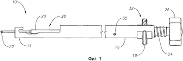
На Фиг.1 показан вид сбоку ручного блока системы для доставки линзы по настоящему изобретению.Figure 1 shows a side view of the hand unit of the lens delivery system of the present invention.
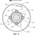
На Фиг.2 показан вид в сечении кольца с шариковым фиксатором ручного блока, представленного на Фиг.1, где замковое кольцо находится в заблокированном положении.Figure 2 shows a sectional view of the ball lock ring of the hand block shown in Figure 1, where the locking ring is in the locked position.
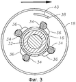
На Фиг.3 показан вид в сечении кольца с шариковым фиксатором ручного блока, представленного на Фиг.1, где замковое кольцо находится в разблокированном положении.Figure 3 shows a cross-sectional view of the ball lock ring of the hand block shown in Figure 1, where the locking ring is in the unlocked position.
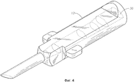
На Фиг.4 показан вид в перспективе картриджа, который может быть использован с системой для доставки линзы по настоящему изобретению.Figure 4 shows a perspective view of a cartridge that can be used with the lens delivery system of the present invention.
На Фиг.5 показан вид в сечении ручного блока системы для доставки линзы по настоящему изобретению.5 is a cross-sectional view of a hand unit of a lens delivery system of the present invention.
ПОДРОБНОЕ ОПИСАНИЕ ИЗОБРЕТЕНИЯDETAILED DESCRIPTION OF THE INVENTION
Как видно на Фиг.1 и 4, система 10 для доставки линзы по настоящему изобретению, в общем, включает в себя картридж 12 и ручной блок 14. Ручной блок 14, в общем, состоит из цилиндра 16, кольца 18 с шариковым фиксатором (показано на Фигуре 1 частично в сечении) и плунжерного стержня 20. Как видно на Фигурах 1 и 5, плунжерный стержень 20 содержит дистальный наконечник 22 и проксимальный конец 23, который смонтирован с возможностью вращения на оси нарезного наружного вала 24, так что наружный вал 24 свободно вращается на проксимальном конце 23 плунжерного стержня 20. На наружном валу 24 жестко закреплена головка 26. Штифт 35 посажен напротив плоского участка 37 плунжерного стержня 20, так что вращение головки 26 и наружного вала 24 не приводят к вращению плунжерного стержня 20, но при этом плунжерный стержень 20 может свободно совершать возвратно-поступательные перемещения в цилиндре 16. Цилиндр 16 содержит участок 28 с выемкой, в который помещают картридж 12, так что наконечник 22 плунжерного стержня 20 совершает возвратно-поступательные перемещения в проходном отверстии (канале) 30 картриджа 12.As can be seen in FIGS. 1 and 4, the
Как видно на Фиг.2 и 3, кольцо 18 с шариковым фиксатором содержит множество шариков 34, размер которых подобран так, чтобы соответствовать канавке 32 наружного вала 24. Кольцо 18 содержит также множество угловых карманов 36, противоположных канавке 32, соответствующих расположению шариков 34. Как показано на Фигуре 2, при повороте кольца 18 с шариковым фиксатором против часовой стрелки шарики 34 заходят в канавку 32 и препятствуют тому, чтобы плунжерный стержень 20 продвигался при нажатии на головку 26. Наоборот, при повороте головки 26 шарики 32 передвигаются в пределах канавки 32 нарезного наружного вала 24, тем самым оказывая выталкивающее или втягивающее усилие на проксимальный конец 23 плунжерного стержня при перемещении по резьбе, что приводит к соответствующему возвратно-поступательному перемещению наконечника 22 плунжерного стержня 20 в проходном отверстии 30 картриджа 12. Как показано на Фиг.3, при повороте кольца 18 с шариковым фиксатором по часовой стрелке шарики 34 выходят из канавки 32, что позволяет плунжерному стержню 20 продвигаться при нажатии на головку 26. Стопорный штифт 38 и паз 40 препятствуют повороту кольца 18 с шариковым фиксатором на чрезмерно большую величину.As can be seen in FIGS. 2 and 3, the
В то время как выше были изложены определенные варианты осуществления настоящего изобретения, данное описание представлено лишь с целью иллюстраций и пояснений. Отклонения, изменения, усовершенствования и отход от вышеизложенных систем и способов могут быть приняты без отхода от объема и сущности настоящего изобретения.While certain embodiments of the present invention have been set forth above, this description is presented for the purpose of illustration and explanation only. Deviations, changes, improvements and departure from the above systems and methods can be accepted without departing from the scope and essence of the present invention.
Claims (6)
a) картридж, имеющий проходное отверстие;
b) ручной блок, причем ручной блок имеет участок с выемкой для приема картриджа;
c) плунжер, коаксиально помещенный в ручной блок, причем плунжер имеет дистальный наконечник и проксимальный конец, противоположный дистальному наконечнику, при этом наконечник совершает возвратно-поступательные перемещения в проходном отверстии картриджа, когда картридж помещен на участок с выемкой в ручном блоке;
d) нарезной наружный вал, помещенный на проксимальном конце плунжера;
e) кольцо с шариковым фиксатором, установленное с возможностью вращения на ручном блоке, причем кольцо с шариковым фиксатором имеет множество фиксирующих шариков, которые перемещаются в пределах канавки наружного вала; и
f) множество угловых карманов в кольце с шариковым фиксатором, соответствующих фиксирующим шарикам, причем угловые карманы поочередно заставляют фиксирующие шарики заходить в канавку наружного вала и выходить из нее в ответ на поворот кольца с шариковым фиксатором.1. A system for delivering an intraocular lens, comprising:
a) a cartridge having a through hole;
b) a hand unit, the hand unit having a recess portion for receiving a cartridge;
c) a plunger coaxially placed in the hand block, the plunger having a distal tip and a proximal end opposite the distal tip, the tip making reciprocating movements in the passage of the cartridge when the cartridge is placed on a recess in the hand block;
d) a threaded outer shaft located at the proximal end of the plunger;
e) a ball lock ring rotatably mounted on the hand unit, the ball lock ring having a plurality of locking balls that move within the groove of the outer shaft; and
f) a plurality of corner pockets in the ball retainer ring corresponding to the retaining balls, the corner pockets alternately causing the locking balls to enter and exit the groove of the outer shaft in response to the rotation of the ball retainer ring.
Applications Claiming Priority (3)
| Application Number | Priority Date | Filing Date | Title |
|---|---|---|---|
| US11/928,554 US8105332B2 (en) | 2007-10-30 | 2007-10-30 | Lens delivery system |
| US11/928,554 | 2007-10-30 | ||
| PCT/US2008/081679 WO2009058929A1 (en) | 2007-10-30 | 2008-10-30 | Lens delivery system |
Publications (2)
| Publication Number | Publication Date |
|---|---|
| RU2010121933A RU2010121933A (en) | 2011-12-10 |
| RU2472468C2 true RU2472468C2 (en) | 2013-01-20 |
Family
ID=40262200
Family Applications (1)
| Application Number | Title | Priority Date | Filing Date |
|---|---|---|---|
| RU2010121933/14A RU2472468C2 (en) | 2007-10-30 | 2008-10-30 | System for lens delivery |
Country Status (18)
| Country | Link |
|---|---|
| US (1) | US8105332B2 (en) |
| EP (1) | EP2150204B1 (en) |
| JP (1) | JP5255064B2 (en) |
| KR (1) | KR101471817B1 (en) |
| CN (1) | CN101815484B (en) |
| AR (1) | AR070664A1 (en) |
| AT (1) | ATE481948T1 (en) |
| AU (1) | AU2008318711B2 (en) |
| BR (1) | BRPI0818794A2 (en) |
| CA (1) | CA2691551C (en) |
| DE (1) | DE602008002748D1 (en) |
| ES (1) | ES2350818T3 (en) |
| IL (1) | IL202868A (en) |
| NZ (1) | NZ582937A (en) |
| RU (1) | RU2472468C2 (en) |
| TW (1) | TWI422363B (en) |
| WO (1) | WO2009058929A1 (en) |
| ZA (1) | ZA201000429B (en) |
Families Citing this family (50)
| Publication number | Priority date | Publication date | Assignee | Title |
|---|---|---|---|---|
| WO2006070628A1 (en) | 2004-12-27 | 2006-07-06 | Hoya Corporation | Intraocular lens implanting device |
| US8545512B2 (en) * | 2005-01-26 | 2013-10-01 | Hoya Corporation | Intraocular lens insertion device |
| JP4836046B2 (en) | 2005-02-24 | 2011-12-14 | Hoya株式会社 | Intraocular lens insertion device |
| US8574239B2 (en) * | 2005-09-28 | 2013-11-05 | Hoya Corporation | Intraocular lens insertion device |
| JP4877643B2 (en) * | 2005-12-08 | 2012-02-15 | Hoya株式会社 | Intraocular lens insertion device |
| US8460375B2 (en) * | 2006-08-14 | 2013-06-11 | Novartis Ag | Lens delivery system |
| US9522061B2 (en) * | 2007-02-15 | 2016-12-20 | Novartis Ag | Lens delivery system |
| US20080255577A1 (en) * | 2007-04-11 | 2008-10-16 | Downer David A | Lens Delivery System Cartridge and Method of Manufacture |
| JP5236637B2 (en) | 2007-05-30 | 2013-07-17 | Hoya株式会社 | Intraocular lens insertion device and intraocular lens insertion device |
| EP2161005B1 (en) | 2007-05-30 | 2016-12-28 | Hoya Corporation | Intraocular lens inserting tool |
| JP5086713B2 (en) * | 2007-07-11 | 2012-11-28 | Hoya株式会社 | Intraocular lens insertion device |
| AU2009212211B2 (en) | 2008-02-07 | 2013-03-14 | Alcon Inc. | Lens delivery system cartridge |
| JP5254669B2 (en) * | 2008-06-05 | 2013-08-07 | Hoya株式会社 | Intraocular lens insertion device and cartridge |
| JP5470753B2 (en) * | 2008-06-17 | 2014-04-16 | Hoya株式会社 | Intraocular lens insertion device |
| JP5323420B2 (en) | 2008-08-21 | 2013-10-23 | Hoya株式会社 | Intraocular lens insertion device |
| JP5416379B2 (en) | 2008-09-04 | 2014-02-12 | Hoya株式会社 | Intraocular lens insertion device |
| US8801780B2 (en) | 2008-10-13 | 2014-08-12 | Alcon Research, Ltd. | Plunger tip coupling device for intraocular lens injector |
| US8308736B2 (en) * | 2008-10-13 | 2012-11-13 | Alcon Research, Ltd. | Automated intraocular lens injector device |
| US8808308B2 (en) | 2008-10-13 | 2014-08-19 | Alcon Research, Ltd. | Automated intraocular lens injector device |
| CN102307543B (en) | 2009-01-07 | 2015-10-21 | Hoya株式会社 | Intraocular lens inserting instrument |
| EP2395951B1 (en) | 2009-01-28 | 2020-07-29 | Alcon Inc. | Ocular implant with stiffness qualities |
| NZ594436A (en) * | 2009-02-11 | 2013-09-27 | Alcon Res Ltd | Automated intraocular lens injector device |
| US9326847B2 (en) | 2010-04-08 | 2016-05-03 | Hoya Corporation | Ocular implant insertion apparatus and methods |
| US8308799B2 (en) | 2010-04-20 | 2012-11-13 | Alcon Research, Ltd. | Modular intraocular lens injector device |
| JP5511530B2 (en) | 2010-06-10 | 2014-06-04 | Hoya株式会社 | Intraocular lens insertion device |
| GB201011313D0 (en) | 2010-07-05 | 2010-08-18 | Ucl Business Plc | Implantation devices, methods and implants |
| US8579969B2 (en) | 2010-07-25 | 2013-11-12 | Alcon Research, Ltd. | Dual mode automated intraocular lens injector device |
| EP2567674B1 (en) * | 2011-09-07 | 2015-05-06 | SDI Surgical Device International GmbH | Modular intraocular lens injector |
| US8690941B2 (en) | 2011-10-04 | 2014-04-08 | Novartis Ag | Intraocular lens surgical system and method |
| US8657835B2 (en) | 2012-01-27 | 2014-02-25 | Alcon Research, Ltd. | Automated intraocular lens injector device |
| GB2501109B (en) | 2012-04-12 | 2014-04-23 | Duckworth & Kent Ltd | Actuator for device for delivery of ophthalmic lenses |
| WO2013158919A1 (en) * | 2012-04-19 | 2013-10-24 | Transcend Medical, Inc. | Delivery system for ocular implant |
| US10085633B2 (en) | 2012-04-19 | 2018-10-02 | Novartis Ag | Direct visualization system for glaucoma treatment |
| US9241832B2 (en) | 2012-04-24 | 2016-01-26 | Transcend Medical, Inc. | Delivery system for ocular implant |
| US9504561B2 (en) * | 2013-03-07 | 2016-11-29 | Novartis Ag | Systems and processes for inserting an intraocular lens |
| GB2517921B (en) | 2013-09-04 | 2015-12-16 | Duckworth & Kent Ltd | Device for use in a delivery of ophthalmic lenses |
| ES2838600T3 (en) | 2014-04-17 | 2021-07-02 | Healeon Medical Ltd | Apparatus for the preparation and administration of blood components |
| CN107920891A (en) | 2015-09-16 | 2018-04-17 | Hoya株式会社 | Intraocular lens inserting instrument |
| JP6646987B2 (en) | 2015-09-16 | 2020-02-14 | Hoya株式会社 | Intraocular lens insertion device |
| US10722347B2 (en) * | 2015-12-17 | 2020-07-28 | Atrion Medical Products, Inc. | Intraocular lens delivery device and method of use |
| US11000410B2 (en) * | 2016-06-17 | 2021-05-11 | Gyroscope Therapeutics Limited | Guide apparatus for tangential entry into suprachoroidal space |
| KR102431211B1 (en) * | 2016-06-28 | 2022-08-09 | 호야 가부시키가이샤 | Intraocular lens injector |
| CN108324425B (en) * | 2018-02-09 | 2020-05-12 | 杭州科锐特医疗设备有限公司 | Medical auditory canal cleaning device for single hand |
| CH714883A1 (en) * | 2018-04-12 | 2019-10-15 | Medicel Ag | Injector with two operating modes, in particular suitable for injecting an intraocular lens. |
| TW202005618A (en) | 2018-07-10 | 2020-02-01 | 瑞士商愛爾康股份有限公司 | Intraocular lens injector |
| EP3593838A1 (en) * | 2018-07-13 | 2020-01-15 | Zyno Medical, Llc | High precision syringe with removable pump unit |
| JP2023543559A (en) * | 2020-09-04 | 2023-10-17 | オフサルモ・プロ・ゲゼルシャフト・ミト・ベシュレンクテル・ハフツング | Inserter for intraocular lenses |
| JP2023543142A (en) * | 2020-09-04 | 2023-10-13 | オフサルモ・プロ・ゲゼルシャフト・ミト・ベシュレンクテル・ハフツング | Inserter for intraocular lenses |
| DE102020126789A1 (en) * | 2020-10-13 | 2022-04-14 | OphthalmoPro GmbH | Injector for intraocular lenses |
| DE102021112682B3 (en) | 2021-05-17 | 2022-09-15 | Iolution Gmbh | Injector with rotating element for an intraocular lens |
Citations (4)
| Publication number | Priority date | Publication date | Assignee | Title |
|---|---|---|---|---|
| SU1715347A1 (en) * | 1989-06-14 | 1992-02-28 | Malov Vladimir M | Device for implanting posterochamber intraocular lenses |
| US5876406A (en) * | 1996-08-02 | 1999-03-02 | Staar Surgical Company, Inc. | Deformable intraocular lens injecting apparatus with transverse hinged lens cartridge |
| WO2004010903A1 (en) * | 2002-07-29 | 2004-02-05 | Duckworth & Kent Limited | Delivery of ophthalmic lenses |
| US20040243141A1 (en) * | 2003-05-28 | 2004-12-02 | Kyle Brown | Lens delivery system |
Family Cites Families (20)
| Publication number | Priority date | Publication date | Assignee | Title |
|---|---|---|---|---|
| US4681102A (en) * | 1985-09-11 | 1987-07-21 | Bartell Michael T | Apparatus and method for insertion of an intra-ocular lens |
| US5306248A (en) * | 1992-04-07 | 1994-04-26 | C. R. Bard, Inc. | Selectively controllable inflation-deflation device adapted for use in angioplasty procedures |
| US5499987A (en) * | 1992-09-30 | 1996-03-19 | Staar Surgical Company | Deformable intraocular lens cartridge |
| DE69331807T2 (en) * | 1992-09-30 | 2002-09-26 | Vladimir Feingold | INTRAOCULAR LENS INSERTION SYSTEM |
| US5616148A (en) * | 1992-09-30 | 1997-04-01 | Staar Surgical Company, Inc. | Transverse hinged deformable intraocular lens injecting apparatus |
| US5620450A (en) * | 1992-09-30 | 1997-04-15 | Staar Surgical Company, Inc. | Transverse hinged deformable intraocular lens injecting apparatus |
| US5275604A (en) * | 1992-12-03 | 1994-01-04 | Kabi Pharmacia Ophthalmics, Inc. | Contoured duct apparatus and method for insertion of flexible intraocular lens |
| US5653715A (en) * | 1993-03-09 | 1997-08-05 | Chiron Vision Corporation | Apparatus for preparing an intraocular lens for insertion |
| CN1177919A (en) * | 1995-03-10 | 1998-04-01 | 托马斯·J·钱伯斯 | Deformable intraocular lens insertion system |
| US5643276A (en) * | 1995-10-10 | 1997-07-01 | Allergan | Apparatus and method for providing desired rotational orientation to an intraocular lens |
| GB0007071D0 (en) * | 2000-03-24 | 2000-05-17 | Sams Bernard | One-way clutch mechanisms and injector devices |
| US6796987B2 (en) * | 2001-07-16 | 2004-09-28 | Stryker Instruments | Delivery device for bone cement |
| ITMI20022196A1 (en) * | 2002-10-16 | 2004-04-17 | Lorenzo Bormioli | QUICK-RELEASE CONNECTOR AND QUICK RELEASE OF SAFETY FOR PIPES. |
| EP1419748B1 (en) * | 2002-11-18 | 2006-07-19 | Anton Meyer & Co.AG | Lens injector with finger ring |
| CN100411597C (en) * | 2003-02-08 | 2008-08-20 | 佳能星股份有限公司 | Inserting arrangement for deformable eye crystalline lens |
| FR2875125B1 (en) * | 2004-09-13 | 2006-12-01 | Patrick Meunier | DEVICE FOR LOADING AN INTRAOCULAR LENS IN AN INJECTION CARTRIDGE |
| WO2006070628A1 (en) * | 2004-12-27 | 2006-07-06 | Hoya Corporation | Intraocular lens implanting device |
| US7722622B2 (en) * | 2005-02-25 | 2010-05-25 | Synthes Usa, Llc | Implant insertion apparatus and method of use |
| US7740636B2 (en) * | 2005-04-15 | 2010-06-22 | Abbott Medical Optics Inc. | Multi-action device for inserting an intraocular lens into an eye |
| US8574239B2 (en) | 2005-09-28 | 2013-11-05 | Hoya Corporation | Intraocular lens insertion device |
-
2007
- 2007-10-30 US US11/928,554 patent/US8105332B2/en active Active
-
2008
- 2008-10-30 DE DE602008002748T patent/DE602008002748D1/en active Active
- 2008-10-30 BR BRPI0818794 patent/BRPI0818794A2/en not_active IP Right Cessation
- 2008-10-30 RU RU2010121933/14A patent/RU2472468C2/en not_active IP Right Cessation
- 2008-10-30 KR KR1020097027467A patent/KR101471817B1/en not_active IP Right Cessation
- 2008-10-30 ES ES08844603T patent/ES2350818T3/en active Active
- 2008-10-30 NZ NZ582937A patent/NZ582937A/en not_active IP Right Cessation
- 2008-10-30 AR ARP080104766A patent/AR070664A1/en not_active Application Discontinuation
- 2008-10-30 CA CA2691551A patent/CA2691551C/en not_active Expired - Fee Related
- 2008-10-30 AU AU2008318711A patent/AU2008318711B2/en not_active Ceased
- 2008-10-30 EP EP08844603A patent/EP2150204B1/en active Active
- 2008-10-30 JP JP2010531333A patent/JP5255064B2/en active Active
- 2008-10-30 TW TW097141774A patent/TWI422363B/en not_active IP Right Cessation
- 2008-10-30 AT AT08844603T patent/ATE481948T1/en not_active IP Right Cessation
- 2008-10-30 WO PCT/US2008/081679 patent/WO2009058929A1/en active Application Filing
- 2008-10-30 CN CN2008801003014A patent/CN101815484B/en not_active Expired - Fee Related
-
2009
- 2009-12-21 IL IL202868A patent/IL202868A/en not_active IP Right Cessation
-
2010
- 2010-01-20 ZA ZA2010/00429A patent/ZA201000429B/en unknown
Patent Citations (4)
| Publication number | Priority date | Publication date | Assignee | Title |
|---|---|---|---|---|
| SU1715347A1 (en) * | 1989-06-14 | 1992-02-28 | Malov Vladimir M | Device for implanting posterochamber intraocular lenses |
| US5876406A (en) * | 1996-08-02 | 1999-03-02 | Staar Surgical Company, Inc. | Deformable intraocular lens injecting apparatus with transverse hinged lens cartridge |
| WO2004010903A1 (en) * | 2002-07-29 | 2004-02-05 | Duckworth & Kent Limited | Delivery of ophthalmic lenses |
| US20040243141A1 (en) * | 2003-05-28 | 2004-12-02 | Kyle Brown | Lens delivery system |
Also Published As
| Publication number | Publication date |
|---|---|
| AU2008318711A1 (en) | 2009-05-07 |
| ZA201000429B (en) | 2011-03-30 |
| WO2009058929A1 (en) | 2009-05-07 |
| CA2691551C (en) | 2015-12-22 |
| KR101471817B1 (en) | 2014-12-11 |
| DE602008002748D1 (en) | 2010-11-04 |
| CN101815484A (en) | 2010-08-25 |
| ATE481948T1 (en) | 2010-10-15 |
| CN101815484B (en) | 2012-10-10 |
| CA2691551A1 (en) | 2009-05-07 |
| AR070664A1 (en) | 2010-04-28 |
| AU2008318711B2 (en) | 2014-01-16 |
| EP2150204A1 (en) | 2010-02-10 |
| KR20100071947A (en) | 2010-06-29 |
| US8105332B2 (en) | 2012-01-31 |
| RU2010121933A (en) | 2011-12-10 |
| TWI422363B (en) | 2014-01-11 |
| IL202868A (en) | 2015-03-31 |
| NZ582937A (en) | 2012-06-29 |
| US20090112223A1 (en) | 2009-04-30 |
| EP2150204B1 (en) | 2010-09-22 |
| BRPI0818794A2 (en) | 2015-04-22 |
| TW200930344A (en) | 2009-07-16 |
| JP2011502012A (en) | 2011-01-20 |
| JP5255064B2 (en) | 2013-08-07 |
| ES2350818T3 (en) | 2011-01-27 |
Similar Documents
| Publication | Publication Date | Title |
|---|---|---|
| RU2472468C2 (en) | System for lens delivery | |
| US7892282B2 (en) | Methods and apparatus for inserting an intraocular lens into an eye | |
| US20240122699A1 (en) | Systems and processes for inserting an intraocular lens | |
| US7892283B2 (en) | Methods and apparatus for inserting an intraocular lens into an eye | |
| RU2375992C2 (en) | System of lens introduction | |
| JP4546549B2 (en) | Intraocular lens delivery device | |
| CA2596760C (en) | Lens delivery system | |
| CA2552984A1 (en) | Intraocular lens injector | |
| US20070265636A1 (en) | Lens delivery system |
Legal Events
| Date | Code | Title | Description |
|---|---|---|---|
| MM4A | The patent is invalid due to non-payment of fees |
Effective date: 20181031 |