RU2472033C2 - Bore-hole pump actuating device - Google Patents
Bore-hole pump actuating device Download PDFInfo
- Publication number
- RU2472033C2 RU2472033C2 RU2009111175/06A RU2009111175A RU2472033C2 RU 2472033 C2 RU2472033 C2 RU 2472033C2 RU 2009111175/06 A RU2009111175/06 A RU 2009111175/06A RU 2009111175 A RU2009111175 A RU 2009111175A RU 2472033 C2 RU2472033 C2 RU 2472033C2
- Authority
- RU
- Russia
- Prior art keywords
- elastic element
- head
- traverses
- suspension
- balancer
- Prior art date
Links
Images
Abstract
Description
Изобретение относится к нефтедобывающей отрасли и может быть использовано для глубинно-насосных скважин со структурообразующей добываемой нефтью.The invention relates to the oil industry and can be used for deep-well wells with structure-forming produced oil.
Известно, что остановка добывающих скважин с нефтью, содержащей достаточное количество парафина, приводит к тиксотропному образованию в ней структуры и появлению статических или предельных динамических напряжений сдвига. В период запуска установки в работу происходит так называемое «зависание» колонны насосных штанг при ходе вниз. Происходит опережение головки балансира, и последующий ход вверх сопровождает ударом, приводящим к поломкам оборудования.It is known that stopping production wells with oil containing a sufficient amount of paraffin leads to the thixotropic formation of a structure in it and the appearance of static or ultimate dynamic shear stresses. During the start-up of the installation, the so-called “freezing” of the string of pump rods occurs during the downward stroke. The head of the balancer is ahead of its head, and the subsequent upward move accompanies a blow, leading to equipment breakdowns.
Наиболее близким к предлагаемому изобретению является устройство для запуска глубинного насоса в работу в скважинах со структурообразующей жидкостью, содержащее канатную подвеску, траверсы, упорные втулки, замкнутую полость с двумя клапанами (SU 1548517, 07.03.1990).Closest to the proposed invention is a device for starting a submersible pump to work in wells with a structure-forming fluid, comprising a cable suspension, traverses, thrust bushings, a closed cavity with two valves (SU 1548517, 03.03.1990).
В этой установке между канатной подвеской и колонной насосных штанг расположен цилиндр с глухим поршнем. Установка обладает низкой надежностью ввиду того, что нагрузка от подземного оборудования передается головке балансира через глухой поршень как в рабочем положении, так и в период запуска. Происходит быстрый износ и поломки такого поршня от больших нагрузок веса штанг и жидкости в насосно-компрессорных трубах.In this installation, a cylinder with a blind piston is located between the cable suspension and the string of pump rods. The installation has low reliability due to the fact that the load from the underground equipment is transferred to the head of the balancer through a blind piston both in the working position and during the start-up period. This piston quickly deteriorates and breaks down due to heavy loads of rod and fluid weights in tubing.
Задача, поставленная в изобретении, - повышение надежности работы устройства.The task set in the invention is to increase the reliability of the device.
Поставленная задача и технический результат достигаются тем, что в устройстве, включающем канатную подвеску, траверсы, упорные втулки, замкнутую полость с двумя клапанами, между двумя траверсами подвески установлен тороидальный упругий элемент, образующий замкнутую полость, связанную с атмосферой с помощью входного клапана большого диаметра и подпружиненного выходного клапана малого диаметра, причем высота упругого элемента в разжатом положении не меньше величины отставания полированного штока от головки балансира при ходе вниз.The task and the technical result are achieved by the fact that in the device including the cable suspension, traverses, thrust bushings, a closed cavity with two valves, a toroidal elastic element is installed between the two traverses of the suspension, forming a closed cavity connected to the atmosphere using an inlet valve of large diameter and a spring-loaded outlet valve of small diameter, and the height of the elastic element in the open position is not less than the lag of the polished rod from the head of the balancer during the down stroke.
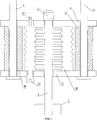
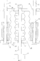
На фиг.1 показана схема устройства в обычном (рабочем) положении, на фиг.2 - в период запуска установки в работу при отставании штанговой колонны от головки балансира.Figure 1 shows a diagram of the device in the normal (operating) position, figure 2 - during the start-up of the installation in operation when the rod column lags from the head of the balancer.
Скважина 1 оборудована штанговой насосной установкой, приводимой в движение станком-качалкой. Привод осуществляется через полированный шток 2, закачивающийся вверху клиновым зажимом 3, канаты 4 и 5, связанные с головкой балансира станка-качалки и проходящие через верхнюю 6 и нижнюю 7 траверсы, а также установленные между ними упорные втулки 8 и 9. Между верхней траверсой 6 и нижней траверсой 7 размещен упругий тороидальный элемент 10, заполненный воздухом и имеющий сообщение с атмосферой через шариковые клапаны 11 (выходной) и 12 (входной). Диаметр клапана 12 существенно превышает диаметр подпружиненного клапана 11. Через клапан 12 атмосферный воздух входит в герметичную полость упругого элемента 10 при его расширении, а через клапан 11 воздух выходит из элемента 10 при его сжатии. Расширение элемента 10 вследствие увеличенного диаметра клапана 12 происходит быстро, а сжатие из-за малого диаметра клапана 12 - медленно.Well 1 is equipped with a sucker rod pump driven by a rocking machine. The drive is carried out through a polished
Работа устройства происходит следующим образом.The operation of the device is as follows.
В период хода головки балансира вниз из-за сильного торможения колонны штанг в высоковязкой структурированной среде произойдет отставание полированного штока 2 от головки балансира. При этом траверсы 6 и 7 будут продолжать движение вниз, а расстояние между зажимом 3 и траверсой 6 будет увеличиваться. Элемент 10 благодаря своей упругости будет, следуя за зажимом 3, расширяться за счет свободного прохождения воздуха через клапан 12 увеличенного размера. Высота тороидального упругого элемента в разжатом положении выбирается не меньше величины отставания полированного штока от головки балансира при ходе вниз.During the stroke of the head of the balancer down due to strong braking of the column of rods in a highly viscous structured medium, the polished
По достижении крайнего нижнего положения головка балансира, канаты 4, 5 и траверсы 6 и 7 начнут движение вверх (фиг.2). Полированный шток и колонна штанг также сразу начнут движение вверх благодаря тому, что передаваемая нагрузка сжатия на элемент 10 не позволит последнему быстро деформироваться ввиду малого диаметра подпружиненного клапана 11 и медленному выходу воздуха из элемента 10. Таким образом, величина хода вверх штангового насоса будет временно уменьшена, но движение штанговой колонны вверх произойдет уже в безударном режиме. При дальнейшем движении колонны штанг и полированного штока вверх нагрузка сжатия, передаваемая от зажима 3 элементу 10, постепенно вернет к концу хода упругий элемент 10 в сжатое начальное положение за счет выхода воздуха через клапан 12.Upon reaching the lowest position, the head of the balancer, ropes 4, 5 and traverse 6 and 7 will begin to move upward (figure 2). The polished rod and the rod string will also immediately begin to move upward, because the transmitted compression load on the
При следующем движении колонны штанг вниз произойдет повторное отставание полированного штока 2 от канатной подвески и расширение упругого элемента 10. Ввиду того, что при этом вязкость жидкости за счет разрушения ее структуры после первого движения уменьшится, величина отставания полированного штока 2 от головки балансира также несколько уменьшится. Наконец, наступит момент полного разрушения структуры жидкости в колонне насосно-компрессорных труб, и дальнейшая работа установки будет происходить без отставания полированного штока. Упругий элемент 10 при этом будет находиться постоянно в сжатом положении при обоих ходах полированного штока, а траверса 6 будет передавать нагрузки оборудования траверсе 7 и далее головке балансира через втулки 8 и 9.During the next downward movement of the rod string, the polished
Технико-экономическим преимуществом предлагаемого устройства является обеспечение безударного режима работы установки в период пуска скважины с высоковязкой нефти и предупреждение преждевременного обрыва колонны штанг. Кроме того, для работы устройства не требуются какие-либо энергозатраты. Устройство имеет простое исполнение и надежность в работе благодаря передаче нагрузок от веса штанг и жидкости на балансир по стандартной схеме - через втулки 8 и 9.The technical and economic advantage of the proposed device is to provide an unshocked mode of operation of the installation during the start-up of a well with high viscosity oil and to prevent premature breakage of the rod string. In addition, the device does not require any energy consumption. The device has a simple design and reliability in operation due to the transfer of loads from the weight of the rods and liquid to the balancer according to the standard scheme - through
Claims (1)
Priority Applications (1)
| Application Number | Priority Date | Filing Date | Title |
|---|---|---|---|
| RU2009111175/06A RU2472033C2 (en) | 2009-03-26 | 2009-03-26 | Bore-hole pump actuating device |
Applications Claiming Priority (1)
| Application Number | Priority Date | Filing Date | Title |
|---|---|---|---|
| RU2009111175/06A RU2472033C2 (en) | 2009-03-26 | 2009-03-26 | Bore-hole pump actuating device |
Publications (2)
| Publication Number | Publication Date |
|---|---|
| RU2009111175A RU2009111175A (en) | 2010-10-27 |
| RU2472033C2 true RU2472033C2 (en) | 2013-01-10 |
Family
ID=44041818
Family Applications (1)
| Application Number | Title | Priority Date | Filing Date |
|---|---|---|---|
| RU2009111175/06A RU2472033C2 (en) | 2009-03-26 | 2009-03-26 | Bore-hole pump actuating device |
Country Status (1)
| Country | Link |
|---|---|
| RU (1) | RU2472033C2 (en) |
Citations (4)
| Publication number | Priority date | Publication date | Assignee | Title |
|---|---|---|---|---|
| SU1548517A2 (en) * | 1988-05-07 | 1990-03-07 | Всесоюзный научно-исследовательский институт по сбору, подготовке и транспорту нефти и нефтепродуктов | Deep-well sucker-rod pumping unit |
| SU1705610A1 (en) * | 1989-03-31 | 1992-01-15 | Научно-исследовательский институт энергетики и автоматики АН УзССР | Pumping unit |
| US5409356A (en) * | 1992-06-11 | 1995-04-25 | Massie; Lewis E. | Well pumping system with linear induction motor device |
| RU2105198C1 (en) * | 1995-09-27 | 1998-02-20 | Алексей Александрович Худяков | Deep-well sucker-rod pump plant for oil recovery |
-
2009
- 2009-03-26 RU RU2009111175/06A patent/RU2472033C2/en not_active IP Right Cessation
Patent Citations (4)
| Publication number | Priority date | Publication date | Assignee | Title |
|---|---|---|---|---|
| SU1548517A2 (en) * | 1988-05-07 | 1990-03-07 | Всесоюзный научно-исследовательский институт по сбору, подготовке и транспорту нефти и нефтепродуктов | Deep-well sucker-rod pumping unit |
| SU1705610A1 (en) * | 1989-03-31 | 1992-01-15 | Научно-исследовательский институт энергетики и автоматики АН УзССР | Pumping unit |
| US5409356A (en) * | 1992-06-11 | 1995-04-25 | Massie; Lewis E. | Well pumping system with linear induction motor device |
| RU2105198C1 (en) * | 1995-09-27 | 1998-02-20 | Алексей Александрович Худяков | Deep-well sucker-rod pump plant for oil recovery |
Also Published As
| Publication number | Publication date |
|---|---|
| RU2009111175A (en) | 2010-10-27 |
Similar Documents
| Publication | Publication Date | Title |
|---|---|---|
| US8944157B2 (en) | Hydro pneumatic lifting system and method | |
| US9151141B1 (en) | Apparatus and method for modifying loading in a pump actuation string in a well having a subsurface pump | |
| US20190107105A1 (en) | Linear Drive Beam Pumping Unit | |
| CN102900400B (en) | Compact hydraulic oil pumping machine adopting composited pneumatic-hydraulic cylinder | |
| US20130343928A1 (en) | Lift system | |
| CN104019019A (en) | Energy storage type linear motor capsule pump | |
| CN100535439C (en) | Mechanical automatic control hydraulic driving pumping unit | |
| RU2472033C2 (en) | Bore-hole pump actuating device | |
| CN205154107U (en) | Well head hydraulic pressure lifting devices | |
| RU147329U1 (en) | HYDRAULIC RETURNING AND INJURY MOVEMENT | |
| CN103541664A (en) | Hydraulic feedback type sucker rod weighting device | |
| CN102691487A (en) | Complex wave pipe | |
| RU2681770C1 (en) | Method of anchoring tubing in wells operated by sucker-rod pumping units | |
| US2887846A (en) | Hydraulic power unit for deep well pumps | |
| CN103061717B (en) | A kind of four cylinder type hydraulic oil pumps | |
| RU55894U1 (en) | WELL PUMP HYDRAULIC DRIVE | |
| CN203892170U (en) | Energy-storage type linear motor capsule pump | |
| CN106761578B (en) | Adjustable hydraulic oil pumping unit device | |
| CN2782986Y (en) | Hydraulic oil pump | |
| RU2333387C2 (en) | Multiplier-type power driving unit for oil field plant | |
| SU1548517A2 (en) | Deep-well sucker-rod pumping unit | |
| CN2697300Y (en) | Shock-damping dropping resisting device for sucker rod | |
| RU2193111C1 (en) | Hydraulic drive of down-hole pump | |
| RU2601395C1 (en) | Drive of deep-well pump with vacuum balancing | |
| RU135018U1 (en) | Borehole PUMP PUMP FOR OIL AND GAS PRODUCTION |
Legal Events
| Date | Code | Title | Description |
|---|---|---|---|
| MM4A | The patent is invalid due to non-payment of fees |
Effective date: 20130327 |