RU2471170C2 - Method and device for analysing magnetic material and analyser having said device - Google Patents
Method and device for analysing magnetic material and analyser having said device Download PDFInfo
- Publication number
- RU2471170C2 RU2471170C2 RU2010113349/28A RU2010113349A RU2471170C2 RU 2471170 C2 RU2471170 C2 RU 2471170C2 RU 2010113349/28 A RU2010113349/28 A RU 2010113349/28A RU 2010113349 A RU2010113349 A RU 2010113349A RU 2471170 C2 RU2471170 C2 RU 2471170C2
- Authority
- RU
- Russia
- Prior art keywords
- magnetic
- magnetic material
- period
- biological
- component
- Prior art date
Links
Images


Classifications
-
- G—PHYSICS
- G01—MEASURING; TESTING
- G01N—INVESTIGATING OR ANALYSING MATERIALS BY DETERMINING THEIR CHEMICAL OR PHYSICAL PROPERTIES
- G01N33/00—Investigating or analysing materials by specific methods not covered by groups G01N1/00 - G01N31/00
- G01N33/48—Biological material, e.g. blood, urine; Haemocytometers
- G01N33/50—Chemical analysis of biological material, e.g. blood, urine; Testing involving biospecific ligand binding methods; Immunological testing
- G01N33/53—Immunoassay; Biospecific binding assay; Materials therefor
- G01N33/543—Immunoassay; Biospecific binding assay; Materials therefor with an insoluble carrier for immobilising immunochemicals
- G01N33/54313—Immunoassay; Biospecific binding assay; Materials therefor with an insoluble carrier for immobilising immunochemicals the carrier being characterised by its particulate form
- G01N33/54326—Magnetic particles
- G01N33/54333—Modification of conditions of immunological binding reaction, e.g. use of more than one type of particle, use of chemical agents to improve binding, choice of incubation time or application of magnetic field during binding reaction
Landscapes
- Health & Medical Sciences (AREA)
- Immunology (AREA)
- Life Sciences & Earth Sciences (AREA)
- Chemical & Material Sciences (AREA)
- Engineering & Computer Science (AREA)
- Hematology (AREA)
- Urology & Nephrology (AREA)
- Biomedical Technology (AREA)
- Molecular Biology (AREA)
- Microbiology (AREA)
- Cell Biology (AREA)
- Biotechnology (AREA)
- Chemical Kinetics & Catalysis (AREA)
- Food Science & Technology (AREA)
- Medicinal Chemistry (AREA)
- Physics & Mathematics (AREA)
- Analytical Chemistry (AREA)
- Biochemistry (AREA)
- General Health & Medical Sciences (AREA)
- General Physics & Mathematics (AREA)
- Pathology (AREA)
- Investigating Or Analyzing Materials By The Use Of Magnetic Means (AREA)
Abstract
Description
ОБЛАСТЬ ТЕХНИКИFIELD OF TECHNOLOGY
По заявке на патент испрашивается приоритет предварительной заявки на патент US 60/970678 от 7 сентября 2007 г. и заявки на патент Франции FR 0757437 от 7 сентября 2007 г.The patent application claims the priority of provisional patent application US 60/970678 of September 7, 2007 and French patent application FR 0757437 of September 7, 2007.
Настоящее изобретение относится к способу и устройству для анализа магнитного материала и к анализатору, который содержит это устройство.The present invention relates to a method and apparatus for analyzing magnetic material and to an analyzer that comprises this apparatus.
ПРЕДШЕСТВУЮЩИЙ УРОВЕНЬ ТЕХНИКИBACKGROUND OF THE INVENTION
Существуют способы измерения массы магнитного материала, содержащие этапы, на которых:There are methods for measuring the mass of magnetic material, comprising stages in which:
a) намагничивают магнитный материал одновременно:a) magnetize magnetic material at the same time:
намагничивающим низкочастотным магнитным полем периодов TL, причем период TL содержит по меньшей мере первый и второй промежутки периода, так чтобы среднее значение мгновенного значения (напряженности) низкочастотного магнитного поля за первый промежуток периода отличалось от среднего значения его мгновенного значения (напряженности) за второй промежуток периода, при этом каждый промежуток периода имеет продолжительность по меньшей мере в 100 наносекунд, иmagnetizing low-frequency magnetic field of periods T L , and the period T L contains at least the first and second intervals of the period, so that the average value of the instantaneous value (intensity) of the low-frequency magnetic field for the first period of the period differs from the average value of its instantaneous value (intensity) for the second a period period, wherein each period period has a duration of at least 100 nanoseconds, and
намагничивающим высокочастотным магнитным полем, изменение мгновенного значения (напряженности) по времени которого является периодическим с частотой fH, при этом частота fH намагничивающего высокочастотного магнитного поля составляет по меньшей мере удвоенную частоту fL низкочастотного магнитного поля.magnetizing high-frequency magnetic field, the change in instantaneous value (intensity) in time which is periodic with a frequency f H , while the frequency f H of the magnetizing high-frequency magnetic field is at least twice the frequency f L of the low-frequency magnetic field.
Такой способ описан, например, в EP 1262766 для измерения количества магнитных частиц в среде для анализа. Способ работает очень хорошо.Such a method is described, for example, in EP 1262766 for measuring the amount of magnetic particles in an analysis medium. The method works very well.
Однако в настоящее время желательно обеспечивать возможность измерения массы магнитного материала, например, имеющегося в среде для анализа, с большей чувствительностью.However, it is currently desirable to provide the ability to measure the mass of magnetic material, for example, available in the analysis medium, with greater sensitivity.
КРАТКОЕ ИЗЛОЖЕНИЕ СУЩЕСТВА ИЗОБРЕТЕНИЯSUMMARY OF THE INVENTION
Одним объектом изобретения является способ измерения массы магнитного материала, также содержащий этапы, на которых:One object of the invention is a method for measuring the mass of magnetic material, also containing stages in which:
b) создают сигнатуру S(H) магнитного материала, сформированную по меньшей мере из двух точек S(H)P, при этом создание содержит получение значения каждой точки S(H)P, посредством измерения за каждый промежуток периода, амплитуды гармоники (напряженности) магнитного поля, индуцированного в магнитном материале, причем амплитуду получают в ответ на намагничивание в течение указанного промежутка периода, при этом гармоника имеет частоту nfH, где n является ненулевым положительным целым числом; иb) create a signature S (H) of the magnetic material formed from at least two points S (H) P , the creation comprising obtaining the value of each point S (H) P , by measuring for each period of the period, the harmonic amplitude (tension) a magnetic field induced in the magnetic material, the amplitude being obtained in response to magnetization during a specified period of time, wherein the harmonic has a frequency nf H , where n is a nonzero positive integer; and
c) идентифицируют и/или определяют массу магнитного материала по нескольким точкам созданной сигнатуры S(H).c) identify and / or determine the mass of the magnetic material from several points of the generated signature S (H).
Может быть показано, что сигнатура S(H) приблизительно равна производной n-ого порядка от магнитной индукции B (Тесла) по напряженности магнитного поля H (Ампер на метр). Следовательно, может быть записано следующее уравнение:It can be shown that the signature S (H) is approximately equal to the nth derivative of the magnetic induction B (Tesla) with respect to the magnetic field strength H (Ampere per meter). Therefore, the following equation can be written:
![]()
![]()
где B является магнитной индукцией как функция от напряженности магнитного поля H.where B is magnetic induction as a function of magnetic field H.
В EP 1262766 указано, что существует возможность изолировать амплитуду гармоники частоты nfH. Однако для этого используют только средний результат измерений низкочастотного магнитного поля, сделанных по нескольким периодам TL. При этих условиях измеренная амплитуда S(0) приблизительно равна dnB(0)/dHn, то есть приблизительно равна значению производной n-го порядка от индукции B по (напряженности) магнитного поля для нулевого поля. Соответственно, количество магнитных частиц в среде для анализа определяют только из точки S(0).EP 1262766 states that it is possible to isolate the harmonic amplitude of a frequency nf H. However, for this, only the average result of measurements of the low-frequency magnetic field made over several periods T L is used . Under these conditions, the measured amplitude S (0) is approximately equal to d n B (0) / dH n , that is, approximately equal to the value of the nth derivative of the induction B with respect to the (magnetic field) magnetic field for the zero field. Accordingly, the number of magnetic particles in the medium for analysis is determined only from the point S (0).
Однако в вышеупомянутом способе измерения амплитуду гармоники частоты nfH измеряют поочередно за первый и второй промежутки периода TL. Здесь первый и второй промежутки периода выбирают так, чтобы среднее значение мгновенного значения (напряженности) низкочастотного магнитного поля за первый промежуток периода было отлично от среднего мгновенного значения (напряженности) этого поля за второй промежуток периода. Здесь, средние значения мгновенного значения (напряженности) низкочастотного магнитного поля за первый и второй промежутки периода обозначены как H1 и H2, соответственно. Амплитуды гармоники частоты nfH за первый и второй промежутки периода приблизительно равны dnB(H1)/dHn и dnB(H2)/dHn, соответственно. Значения dnB(H1)/dHn и dnB(H2)/dHn обозначены здесь S(H1) и S(H2), соответственно.However, in the aforementioned measurement method, the harmonic amplitude of the frequency nf H is measured alternately for the first and second intervals of the period T L. Here, the first and second periods of the period are chosen so that the average value of the instantaneous value (intensity) of the low-frequency magnetic field for the first period of the period is different from the average instant value (intensity) of this field for the second period of the period. Here, the average values of the instantaneous value (intensity) of the low-frequency magnetic field for the first and second intervals of the period are indicated as H 1 and H 2 , respectively. The harmonic amplitudes of the frequency nf H for the first and second periods of the period are approximately equal to d n B (H 1 ) / dH n and d n B (H 2 ) / dH n , respectively. The values of d n B (H 1 ) / dH n and d n B (H 2 ) / dH n are indicated here by S (H 1 ) and S (H 2 ), respectively.
Таким образом, созданная сигнатура S(H) состоит по меньшей мере из двух точек S(H1) и S(H2). Как в EP 1262766, значение каждой из указанных точек является показательным для массы магнитного материала, находящегося в среде для анализа. Однако в вышеупомянутом способе для идентификации или определения массы магнитного материала используют по меньшей мере две точки S(H1) и S(H2) сигнатуры S(H). Использование двух точек S(H1) и S(H2) сигнатуры S(H) улучшает помехоустойчивость по сравнению со случаем, в котором используют только одну точку S(0) амплитуды.Thus, the created signature S (H) consists of at least two points S (H 1 ) and S (H 2 ). As in EP 1262766, the value of each of these points is indicative of the mass of magnetic material in the medium for analysis. However, in the above method, at least two points S (H 1 ) and S (H 2 ) of signature S (H) are used to identify or determine the mass of the magnetic material. The use of two points S (H 1 ) and S (H 2 ) of the signature S (H) improves noise immunity compared to the case in which only one point S (0) of the amplitude is used.
Дополнительно, при использовании по меньшей мере двух точек сигнатуры S(H) становится проще отличать магнитные материалы, имеющие отличные сигнатуры, и следовательно, идентифицировать магнитные материалы с использованием вышеупомянутого способа.Additionally, when using at least two points of the signature S (H), it becomes easier to distinguish between magnetic materials having excellent signatures, and therefore to identify magnetic materials using the aforementioned method.
Варианты осуществления этого способа могут содержать один или большее количество из следующих этапов, на которых:Embodiments of this method may comprise one or more of the following steps, in which:
a) автоматически идентифицируют магнитный материал как функцию от результата корреляции сигнатуры S(H) с каждой из опорных сигнатур Sref(H)i из набора нескольких опорных сигнатур, причем каждую опорную сигнатуру Sref(H)i получают с использованием магнитного материала, отличного от других магнитных материалов, использованных для получения других опорных сигнатур, при этом первый и второй магнитные материалы считают отличными друг от друга, если коэффициент β корреляции между членами совокупности, определенный следующим уравнением, меньше 0,95a) the magnetic material is automatically identified as a function of the result of the correlation of the signature S (H) with each of the reference signatures S ref (H) i from a set of several reference signatures, each reference signature S ref (H) i being obtained using magnetic material other than from other magnetic materials used to obtain other reference signatures, while the first and second magnetic materials are considered different from each other if the correlation coefficient β between the members of the population defined by the following equation is less than 0.95

гдеWhere
![]()
![]()
![]()
![]()
b) определяют массу, для чего:b) determine the mass, for which:
умножают несколько точек сигнатуры S(H), соответственно, на каждую соответствующую точку опорной сигнатуры Sref(H)i, измеренную при идентичных условиях на опорной массе идентичного магнитного материала; иmultiplying several points of the signature S (H), respectively, by each corresponding point of the reference signature S ref (H) i , measured under identical conditions on the reference mass of the same magnetic material; and
вычисляют массу гомогенного магнитного материала как функцию от результата этого умножения;calculating the mass of a homogeneous magnetic material as a function of the result of this multiplication;
c) идентифицируют и/или определяют массу магнитного материала также по меньшей мере на основе одной опорной сигнатуры Sref(H)i, измеренной при идентичных условиях на опорной массе идентичного магнитного материала;c) identifying and / or determining the mass of the magnetic material also based on at least one reference signature S ref (H) i measured under identical conditions on the reference mass of the same magnetic material;
d) создают сигнатуру S(H) магнитного материала путем получения значения каждой точки S(H)p посредством измерения, за каждый промежуток периода, амплитуды и фазы гармоники магнитного поля, индуцированного в магнитном материале, при этом амплитуду и фазу получают в ответ на намагничивание в течение указанного промежутка периода.d) create a signature S (H) of the magnetic material by obtaining the value of each point S (H) p by measuring, for each period, the amplitude and phase of the harmonic of the magnetic field induced in the magnetic material, the amplitude and phase being obtained in response to magnetization during the specified period period.
Указанные варианты осуществления способа также имеют следующие преимущества:These process embodiments also have the following advantages:
- использование результата корреляции сигнатуры S(H) с каждой из опорных сигнатур Sref(H)i обеспечивает возможность автоматической и надежной идентификации массы магнитного материала; и- using the result of correlation of the signature S (H) with each of the reference signatures S ref (H) i provides the possibility of automatic and reliable identification of the mass of magnetic material; and
- поточечное умножение сигнатуры S(H) на опорную сигнатуру Sref(H)i способствует улучшению отношения сигнала к шуму и, следовательно, чувствительности способа.- pointwise multiplication of the signature S (H) by the reference signature S ref (H) i improves the signal-to-noise ratio and, therefore, the sensitivity of the method.
Объектом изобретения также является способ анализа совокупности нескольких различных магнитных материалов, причем первый и второй магнитные материалы считают отличными друг от друга, если коэффициент корреляции β между членами совокупности, определенный следующим уравнением, меньше 0,95The invention also relates to a method for analyzing a population of several different magnetic materials, the first and second magnetic materials being considered different from each other if the correlation coefficient β between the members of the population defined by the following equation is less than 0.95
![]()
![]()
![]()
![]()
![]()
![]()
Согласно изобретению, слово совокупность означает только наличие различных магнитных материалов. Указанные материалы могут быть связаны или нет и/или присутствовать в одной твердой или жидкой фазе.According to the invention, the word collection only means the presence of various magnetic materials. These materials may or may not be bound and / or present in one solid or liquid phase.
Вышеупомянутый способ имеет преимущество в обеспечении возможности идентификации и измерения массы определенного магнитного материала в совокупности из нескольких различных магнитных материалов.The aforementioned method has the advantage of allowing the identification and measurement of the mass of a specific magnetic material in combination of several different magnetic materials.
Варианты осуществления указанного способа анализа совокупности магнитных материалов могут содержать следующий этап, на котором:Embodiments of said method for analyzing a plurality of magnetic materials may comprise the following step in which:
определяют массу каждого из магнитных материалов в совокупности магнитных материалов путем решения следующего матричного уравнения:determine the mass of each of the magnetic materials in the aggregate of magnetic materials by solving the following matrix equation:

гдеWhere
Q является количеством опорных сигнатур, Q равно или больше количества различных магнитных материалов, находящихся в совокупности;Q is the number of reference signatures, Q is equal to or greater than the number of different magnetic materials in the aggregate;
P является количеством точек каждой сигнатуры, P равно или больше двух;P is the number of points of each signature, P is equal to or greater than two;
S(H)j является j-ой точкой сигнатуры S(H);S (H) j is the jth point of the signature S (H);
αi является отношением массы, которая должна быть измерена, для магнитного материала, имеющего сигнатуру Sref(H)i, к опорной массе, использованной для создания сигнатуры Sref(H)i;α i is the ratio of the mass to be measured, for magnetic material having the signature S ref (H) i , to the reference mass used to create the signature S ref (H) i ;
Sref(H)ij является j-ой точкой сигнатуры Sref(H)i;S ref (H) ij is the jth point of the signature S ref (H) i ;
N(H)j является j-ой точкой сигнала, представляющего шум, добавляемый к измерению сигнатуры S(H); иN (H) j is the jth point of the signal representing the noise added to the measurement of the signature S (H); and
"T" является символом функции транспонирования." T " is a symbol for the transpose function.
Этот вариант осуществления способа анализа совокупности магнитных материалов также имеет следующее преимущество:This embodiment of a method for analyzing a plurality of magnetic materials also has the following advantage:
- решение вышеупомянутого матричного уравнения обеспечивает возможность одновременного получения массы каждого из магнитных материалов, содержащихся в совокупности.- the solution of the above matrix equation provides the ability to simultaneously obtain the mass of each of the magnetic materials contained in the aggregate.
Варианты осуществления указанных способов анализа могут также содержать следующий отличительный признак:Embodiments of these analysis methods may also include the following distinguishing feature:
- мгновенное значение (напряженности) низкочастотного магнитного поля в течение каждого из промежутков периода является постоянным.- the instantaneous value (intensity) of the low-frequency magnetic field during each period of the period is constant.
Объектом изобретения также является устройство для анализа магнитного материала, содержащее:The invention also relates to a device for analyzing magnetic material, comprising:
a) генератор, выполненный с возможностью намагничивания магнитного материала одновременно:a) a generator configured to magnetize magnetic material at the same time:
намагничивающим низкочастотным магнитным полем периодов TL, причем период TL содержит по меньшей мере первый и второй промежутки периода, так чтобы среднее значение мгновенного значения (напряженности) низкочастотного магнитного поля за первый промежуток периода было отлично от среднего значения его мгновенного значения (напряженности) за второй промежуток периода, при этом каждый промежуток периода имеет продолжительность по меньшей мере 100 наносекунд, иmagnetizing low-frequency magnetic field of periods T L , and the period T L contains at least the first and second intervals of the period, so that the average value of the instantaneous value (intensity) of the low-frequency magnetic field for the first period of the period was different from the average value of its instantaneous value (intensity) for a second period span, wherein each period span has a duration of at least 100 nanoseconds, and
намагничивающим высокочастотным магнитным полем, изменение мгновенного значения (напряженности) по времени которого является периодическим с частотой fH, при этом частота fH намагничивающего высокочастотного магнитного поля составляет по меньшей мере удвоенную частоту fL низкочастотного магнитного поля,magnetizing high-frequency magnetic field, the change in instantaneous value (intensity) over time which is periodic with a frequency f H , while the frequency f H of the magnetizing high-frequency magnetic field is at least twice the frequency f L of the low-frequency magnetic field,
устройство также содержит:The device also contains:
b) конструктор сигнатуры для создания сигнатуры S(H) магнитного материала, сформированной по меньшей мере из двух точек S(H)P, при этом конструктор выполнен с возможностью получения значения каждой точки S(H)P посредством измерения, за каждый промежуток периода, амплитуды и, возможно, фазы гармоники магнитного поля, индуцированного в магнитном материале, при этом амплитуду и фазу получают в ответ на намагничивание в течение указанного промежутка периода, при этом гармоника имеет частоту nfH, где n является ненулевым положительным целым числом; иb) a signature constructor for creating a signature S (H) of magnetic material formed from at least two points S (H) P , wherein the designer is configured to obtain the value of each point S (H) P by measuring, for each period period, the amplitude and, possibly, the phase of the harmonic of the magnetic field induced in the magnetic material, the amplitude and phase being obtained in response to magnetization during the indicated period of time, while the harmonic has a frequency nf H , where n is a nonzero positive integer; and
c) блок идентификации и/или определения массы магнитного материала на основе нескольких точек созданной сигнатуры S(H).c) an identification and / or mass determination unit for the magnetic material based on several points of the generated signature S (H).
В первом определенном варианте осуществления изобретения, применяемом для детектирования или для количественного определения биологического или химического компонента в образце, совокупность получают следующим образом:In a first specific embodiment of the invention, used to detect or quantify a biological or chemical component in a sample, the population is prepared as follows:
первый магнитный материал, к которому присоединен лиганд, способный к образованию связи с биологическим или химическим компонентом, который должен быть детектирован, смешивают с образцом, который должен быть проанализирован, создавая комплекс магнитных материалов/компонентов;the first magnetic material to which a ligand is attached, capable of forming a bond with the biological or chemical component that must be detected, is mixed with the sample that must be analyzed, creating a complex of magnetic materials / components;
осуществляют концентрирование магнитного комплекса в заданном объеме с использованием магнитного поля;carry out the concentration of the magnetic complex in a given volume using a magnetic field;
затем комплекс приводят в контакт со вторым, отличным магнитным материалом, к которому присоединен лиганд, также способный к образованию связи с идентичным находящимся в первом материале биологическим или химическим компонентом, который должен быть задетектирован, или с реагентом, обеспечивающим возможность детектирования или количественного определения указанного компонента;then the complex is brought into contact with a second, excellent magnetic material, to which a ligand is attached, also capable of forming a bond with the identical biological or chemical component that must be detected in the first material, or with a reagent capable of detecting or quantifying the specified component ;
анализ полученной таким образом совокупности магнитных материалов обеспечивает возможность детектирования и/или количественного определения указанного компонента.analysis of the thus obtained combination of magnetic materials provides the ability to detect and / or quantify the specified component.
Во втором определенном варианте осуществления изобретения, применяемом для детектирования или количественного определения по меньшей мере двух биологических или химических компонентов в образце, совокупность получают посредством смешивания образца:In a second specific embodiment of the invention used to detect or quantify at least two biological or chemical components in a sample, the population is obtained by mixing the sample:
с первым магнитным материалом, который образует связь с первым биологическим или химическим компонентом или с реагентом, обеспечивающим возможность детектирования и/или количественного определения упомянутого компонента;with the first magnetic material, which forms a bond with the first biological or chemical component or with a reagent that enables the detection and / or quantification of said component;
и со вторым отличным магнитным материалом, который образует связь со вторым биологическим или химическим компонентом или с реагентом, обеспечивающим возможность детектирования и/или количественного определения упомянутого компонента.and with a second excellent magnetic material that forms a bond with a second biological or chemical component or with a reagent capable of detecting and / or quantifying said component.
В третьем варианте осуществления изобретения, применяемом для детектирования или количественного определения по меньшей мере двух биологических или химических компонентов в образце, совокупность получают посредством смешивания образца:In a third embodiment of the invention, used to detect or quantify at least two biological or chemical components in a sample, the population is obtained by mixing the sample:
с первым магнитным материалом, который образует связь с биологическим или химическим компонентом, который должен быть определен количественно, или с реагентом, обеспечивающим возможность детектирования и/или количественного определения упомянутого компонента; иwith a first magnetic material that forms a bond with a biological or chemical component to be quantified, or with a reagent capable of detecting and / or quantifying said component; and
со вторым отличным магнитным материалом, который является инертным по отношению к вышеупомянутому компоненту.with a second excellent magnetic material that is inert to the aforementioned component.
Объектом изобретения также является устройство для анализа совокупности различных магнитных материалов, в котором блок идентификации и/или определения выполнен с возможностью идентификации и/или определения массы по меньшей мере одного из магнитных материалов совокупности на основе нескольких точек созданной сигнатуры S(H) и нескольких сигнатур Sref(H)i, каждую из которых измеряют при идентичных условиях на опорной массе каждого из магнитных материалов совокупности.The invention also relates to a device for analyzing a set of different magnetic materials, in which an identification and / or determination unit is configured to identify and / or determine the mass of at least one of the magnetic materials of the set based on several points of the created signature S (H) and several signatures S ref (H) i , each of which is measured under identical conditions on the reference mass of each of the magnetic materials of the population.
И, наконец, объектом изобретения является анализатор для анализа среды для анализа, которая может содержать по меньшей мере один биологический и/или химический компонент, материал, который должен быть проанализирован, содержащий магнитные частицы, связанные с компонентом или реагентом для обеспечения возможности детектирования и/или количественного определения компонента, при этом анализатор содержит:And, finally, the object of the invention is an analyzer for analyzing an analysis medium, which may contain at least one biological and / or chemical component, the material to be analyzed, containing magnetic particles associated with the component or reagent to enable detection and / or quantitative determination of the component, while the analyzer contains:
резервуар для содержания среды для анализа; иreservoir for containing the medium for analysis; and
устройство для измерения массы группы находящихся в среде для анализа магнитных частиц, причем результат этого измерения пропорционален количеству находящегося в среде для анализа компонента, который должен быть проанализирован.a device for measuring the mass of a group of magnetic particles in a medium for analyzing, the result of this measurement being proportional to the amount of the component to be analyzed in the medium for analysis.
В одном варианте осуществления, анализатор предназначен для анализа среды, содержащей по меньшей мере два отличных магнитных материала. В частности, он может быть выполнен с возможностью реализации различных режимов применения для детектирования или количественного определения вышеупомянутых биологических или химических компонентов.In one embodiment, the analyzer is designed to analyze a medium containing at least two distinct magnetic materials. In particular, it can be configured to implement various application modes for detecting or quantifying the aforementioned biological or chemical components.
Изобретение будет более понятно при прочтении последующего описания, приведенного, согласно чертежам, исключительно в виде возможного варианта, не накладывающего ограничений.The invention will be more clear when reading the following description, given, according to the drawings, solely in the form of a possible option, without imposing restrictions.
КРАТКОЕ ОПИСАНИЕ ЧЕРТЕЖЕЙBRIEF DESCRIPTION OF THE DRAWINGS
В дальнейшем изобретение поясняется описанием предпочтительного варианта воплощения со ссылками на сопроводительные чертежи, на которых:The invention is further explained in the description of the preferred embodiment with reference to the accompanying drawings, in which:
Фиг.1 изображает схему анализатора для анализа смеси биологических и/или химических компонентов, находящихся в среде для анализа;Figure 1 depicts a diagram of an analyzer for analyzing a mixture of biological and / or chemical components in the medium for analysis;
Фиг.2 изображает временную диаграмму, показывающую форму волны низкочастотного магнитного поля, используемого в анализаторе фиг.1;FIG. 2 is a timing chart showing a waveform of a low frequency magnetic field used in the analyzer of FIG. 1;
фиг.3 изображает блок-схему способа анализа магнитного материала, выполняемого в анализаторе;figure 3 depicts a flowchart of a method of analysis of magnetic material performed in the analyzer;
фиг.4 изображает диаграмму, второй производной магнитной индукции по напряженности магнитного поля для двух отличных магнитных материалов;4 is a diagram of a second derivative of magnetic induction with respect to magnetic field strength for two different magnetic materials;
фиг.5 изображает блок-схему способа анализа совокупности отличных магнитных материалов, который может быть выполнен в анализаторе;5 depicts a flowchart of a method for analyzing a collection of excellent magnetic materials that can be performed in an analyzer;
фиг.6 и фиг.7 изображает временные диаграммы, иллюстрирующие отличные формы волны низкочастотного магнитное поля, которые могут быть выполнены в анализаторе;FIG. 6 and FIG. 7 are timing diagrams illustrating excellent low-frequency magnetic field waveforms that can be performed in an analyzer; FIG.
фиг.8 изображает диаграмму характеристики магнитной индукции ![]()
![]()
![]()
![]()
ОПИСАНИЕ ПРЕДПОЧТИТЕЛЬНЫХ ВАРИАНТОВ ВОПЛОЩЕНИЯ ИЗОБРЕТЕНИЯDESCRIPTION OF THE PREFERRED EMBODIMENTS OF THE INVENTION
В описании признаки и функции, которые известны специалистам в данной области техники, не будут описаны подробно.In the description, features and functions that are known to those skilled in the art will not be described in detail.
Кроме того, здесь два магнитных материала определяют как идентичные друг другу, если коэффициент β корреляции между членами совокупности, определенный следующим уравнением, превышает a In addition, here two magnetic materials are defined as identical to each other if the correlation coefficient β between the members of the population defined by the following equation exceeds a
![]()
![]()
![]()
![]()
![]()
![]()
Считается, что два магнитных материала отличаются друг от друга, если указанный коэффициент β меньше a.It is believed that two magnetic materials differ from each other if the specified coefficient β is less than a .
Значением a является значение в диапазоне от 0,5 до 0,95. Предпочтительно от 0,85 до 0,95, например равно 0,9 или 0,95. В последующем варианте осуществления значение a принимается равным 0,95.The value of a is a value in the range from 0.5 to 0.95. Preferably, from 0.85 to 0.95, for example, 0.9 or 0.95. In a subsequent embodiment, the value of a is taken to be 0.95.
На фиг.1 показан анализатор 2 для анализа среды 4, которая может содержать по меньшей мере один биологический и/или химический компонент.Figure 1 shows the analyzer 2 for analysis of the medium 4, which may contain at least one biological and / or chemical component.
Среда для анализа содержит магнитные частицы 6, связанные с компонентом или реагентом для обеспечения возможности детектирования или количественного определения компонента. Этим реагентом может быть реагент, образующий связь с компонентом. Этим реагентом может быть аналог компонента, обеспечивающий возможность конкурирования с компонентом при реакции образования связи с другим присутствующим элементом.The analysis medium contains magnetic particles 6 associated with the component or reagent to enable detection or quantification of the component. This reagent may be a reagent that forms a bond with the component. This reagent may be an analogue of a component, allowing for competition with the component in a bond formation reaction with another element present.
В этом возможном варианте предполагается, что химический или биологический компонент, который должен быть проанализирован, образует связь с магнитными частицами. Эти магнитные частицы имеют нелинейный цикл намагничивания B(H) для (напряженности) магнитного поля намагничивания, значение которой изменяется между Hmin и Hmax. Под термином "цикл намагничивания" здесь подразумевается кривая, представляющая изменение магнитной индукции B в магнитных частицах, как функции от значения (напряженности) магнитного поля H намагничивания.In this possible embodiment, it is assumed that the chemical or biological component to be analyzed forms a bond with magnetic particles. These magnetic particles have a non-linear magnetization cycle B (H) for the (intensity) of the magnetization magnetic field, the value of which varies between H min and H max . By the term “magnetization cycle” is meant a curve representing the change in magnetic induction B in magnetic particles as a function of the value (intensity) of the magnetic field H magnetization.
В этом примере магнитные частицы представляют собой гранулы 6 из суперпарамагнитного материала. Указанные гранулы имеют наибольший диаметр, обычно от 1 до 100 нанометров. Используемые здесь суперпарамагнитные материалы, например, идентичны описанным в заявке на патент Франции FR 0510278. Цикл намагничивания указанных суперпарамагнитных материалов также проявляет строгую нелинейность для магнитного поля нулевого намагничивания. Эта строгая нелинейность проявляется в наличии экстремума для нулевого магнитного поля в третьей производной магнитной индукции по напряженности магнитного поля. Указанный экстремум, по абсолютному значению, является наибольшим из экстремумов третьей производной магнитной индукции.In this example, the magnetic particles are granules 6 of superparamagnetic material. These granules have the largest diameter, usually from 1 to 100 nanometers. The superparamagnetic materials used here, for example, are identical to those described in French patent application FR 0510278. The magnetization cycle of these superparamagnetic materials also exhibits strict non-linearity for the zero magnetization field. This strict nonlinearity is manifested in the presence of an extremum for a zero magnetic field in the third derivative of magnetic induction with respect to the magnetic field strength. The specified extremum, in absolute value, is the largest of the extrema of the third derivative of magnetic induction.
Совокупность гранул 6 формирует магнитный материал, для простоты называемый "магнитным материалом 6".The aggregate of granules 6 forms a magnetic material, for simplicity, called "magnetic material 6".
Анализатор 2 содержит резервуар 8 для содержания среды 4 для анализа и устройство 10 для анализа магнитного материала, содержащегося в среде 4.The analyzer 2 contains a reservoir 8 for containing the medium 4 for analysis and a device 10 for analyzing the magnetic material contained in the medium 4.
Термин "среда для анализа" подразумевает разграниченную зону резервуара, показания которой снимает устройство измерения.The term "analysis medium" means the delimited area of the tank, the readings of which are taken by the measuring device.
В виде возможного варианта, резервуаром может быть миниатюрная колонна, заполненная пористым материалом(ами) или тестовая полоска, содержащая по меньшей мере один пористый материал, альтернативно, содержащийся в пакете. Такие резервуары обычно используют в областях диагностики и исследования и измерения загрязняющих веществ (см. например, EP 1262766).Alternatively, the reservoir may be a miniature column filled with porous material (s) or a test strip containing at least one porous material, alternatively contained in a bag. Such tanks are commonly used in the areas of diagnosis and research and measurement of pollutants (see, for example, EP 1262766).
Устройство 10 содержит генератор 12 магнитного поля намагничивания, разработанный для создания магнитной индукции в материале 6.The device 10 includes a magnetization magnetic field generator 12, designed to create magnetic induction in the material 6.
Например, генератор 12 формируют из источника 14 тока, подсоединенного к катушке 16 (индуктивности). Источник 14 выполнен с возможностью генерирования электрического тока, формируемого наложением низкочастотного сигнала и высокочастотного сигнала. Например, здесь низкочастотным сигналом является ступенчатый периодический сигнал, при этом высокочастотный сигнал является синусоидальным. Низкочастотный сигнал имеет частоту fL, по меньшей мере в десять раз меньшую частоты fH высокочастотного сигнала. Как правило, частота fH находится между 1 кГц и 10 МГц.For example, a generator 12 is formed from a current source 14 connected to a coil 16 (inductance). The source 14 is configured to generate an electric current generated by the superposition of a low-frequency signal and a high-frequency signal. For example, here the low-frequency signal is a stepwise periodic signal, while the high-frequency signal is sinusoidal. The low frequency signal has a frequency f L at least ten times lower than the frequency f H of the high frequency signal. Typically, the frequency f H is between 1 kHz and 10 MHz.
Катушка 16 преобразовывает этот электрический сигнал в намагничивающее магнитное поле, близкое к материалу 6. Результирующее намагничивающее магнитное поле формируется наложением низкочастотного намагничивающего магнитного поля HL и высокочастотного намагничивающего магнитного поля HH, создаваемых низкочастотным электрическим сигналом и высокочастотным электрическим сигналом, соответственно.Coil 16 converts this electrical signal into a magnetizing magnetic field close to material 6. The resulting magnetizing magnetic field is formed by superimposing a low-frequency magnetizing magnetic field H L and a high-frequency magnetizing magnetic field H H generated by the low-frequency electric signal and the high-frequency electric signal, respectively.
На фиг.2 показано изменение мгновенного значения напряженности магнитного поля HL по времени.Figure 2 shows the change in the instantaneous value of the magnetic field H L in time.
Здесь каждый период TL (напряженности) магнитного поля HL разделен на r промежутков TP одинаковой продолжительности, где r является целым числом, равным или большим 2. Здесь должен быть идентифицирован магнитный материал, находящийся в резервуаре 8, при этом количество r должно быть равным или большим 3 и, предпочтительно, равным или большим 20. В противном случае, то есть, если отсутствует потребность в идентификации магнитного материала, то количество r может быть равным 2. Для иллюстрации, здесь число r равно 20.Here, each period T L (intensity) of the magnetic field H L is divided into r intervals T P of the same duration, where r is an integer equal to or greater than 2. Here, the magnetic material located in the reservoir 8 should be identified, and the quantity r should be equal to or greater than 3, and preferably equal to or greater than 20. Otherwise, that is, if there is no need to identify the magnetic material, then the amount of r may be 2. For illustration, here the number r is 20.
В каждом промежутке TP мгновенное значение (напряженности) поля HL является постоянным и обозначено HL1. Соответственно, в течение первого промежутка T1 периода TL мгновенное значение (напряженности) магнитного поля HL является постоянным и равно HL1. В течение второго промежутка T2 мгновенное значение (напряженности) магнитного поля HL является постоянным и равно HL2. Здесь в течении периода TL значение (напряженности) магнитного поля HL принимает одиннадцать отличных значений HLi, находящихся между Hmin и Hmax.In each interval T P, the instantaneous value (intensity) of the field H L is constant and denoted by H L1 . Accordingly, during the first period T 1 of the period T L, the instantaneous value (intensity) of the magnetic field H L is constant and equal to H L1 . During the second interval T 2 the instantaneous value (intensity) of the magnetic field H L is constant and equal to H L2 . Here, during the period T L, the value (intensity) of the magnetic field H L takes eleven distinct values of H Li between H min and H max .
Продолжительность каждого промежутка TP составляет по меньшей мере 100 наносекунд. Обычно продолжительность промежутка TP составляет между 100 наносекундами и 10 секундами и, предпочтительно, находится между 1 микросекундой и 10 секундами.The duration of each gap T P is at least 100 nanoseconds. Typically, the length of the gap T P is between 100 nanoseconds and 10 seconds, and is preferably between 1 microsecond and 10 seconds.
(Напряженность) магнитного поля HH намагничивания является синусоидальной и имеет частоту fH.The (intensity) of the magnetic field H H magnetization is sinusoidal and has a frequency f H.
Устройство 10 также содержит датчик 18 для детектирования магнитной индукции B, создаваемой в материале 6. Например, датчик 18 измеряет магнитное поле, созданное магнитной индукцией B в материале 6, и формирует соответствующий сигнал Sm измерения. Например, датчик 18 содержит катушку 20 измерения, подсоединенную ко входу аналого-цифрового преобразователя 22. Датчик 18 может быть заменен другими датчиками, например такими, как датчик Холла, SQUID (сверхпроводящий квантовый интерференционный датчик), устройство GMR (на эффекте супермагниторезистивности) или устройство AMR (на эффекте анизотропной магниторезистивности).The device 10 also includes a sensor 18 for detecting the magnetic induction B generated in the material 6. For example, the sensor 18 measures the magnetic field created by the magnetic induction B in the material 6 and generates a corresponding measurement signal S m . For example, the sensor 18 comprises a measurement coil 20 connected to the input of the analog-to-digital converter 22. The sensor 18 can be replaced by other sensors, such as, for example, a Hall sensor, SQUID (superconducting quantum interference sensor), GMR device (super magnetoresistive effect), or device AMR (on the effect of anisotropic magnetoresistance).
В заключение, устройство 10 содержит конструктор 24 сигнатуры для создания сигнатуры S(H) и блок 26 идентификации и определения массы материала 6.In conclusion, the device 10 includes a signature constructor 24 for creating the signature S (H) and a unit 26 for identifying and determining the mass of the material 6.
Конструктор 24 выполнен с возможностью измерения амплитуды гармоники магнитной индукции в материале 6, полученной только в ответ на намагничивание в течение одного промежутка периода TP. Каждое измерение в течение промежутка TP формирует точку S(H)1P сигнатуры S(H) магнитного материала.The designer 24 is configured to measure the amplitude of the harmonic magnetic induction in the material 6, obtained only in response to magnetization during one period of the period T P. Each measurement over the period T P forms a point S (H) 1P of the signature S (H) of the magnetic material.
Конструктор 24 соединен с памятью 28 для записи отличных точек сигнатуры S(H) в этой памяти. Конструктор 24 также соединен с генератором 12 через линию 25 связи для синхронизации с указанным генератором. В заключение, конструктор 24 соединен с входом блока 26.Constructor 24 is connected to memory 28 to record distinct points of signature S (H) in this memory. The designer 24 is also connected to the generator 12 through the communication line 25 for synchronization with the specified generator. In conclusion, the designer 24 is connected to the input of block 26.
Блок 26 выполнен с возможностью идентификации магнитного материала и определения массы находящегося в среде 4 для анализа магнитного материала, на основе нескольких точек сигнатуры S(H). Для этого блок 26 также соединен с памятью 28.Block 26 is configured to identify the magnetic material and determine the mass of magnetic material in the medium 4 for analysis, based on several points of the signature S (H). For this, block 26 is also connected to memory 28.
Память 28 содержит опорные сигнатуры Sref(H)1 и Sref(H)2 и опорные массы Mref1 и Mref2, используемые для получения указанных опорных сигнатур.The memory 28 comprises reference signatures S ref (H) 1 and S ref (H) 2 and reference masses M ref1 and M ref2 used to obtain said reference signatures.
Теперь будет более подробно описана работа анализатора 2, согласно способу, представленному на фиг.3, в определенном случае, в котором все частицы 6 выполнены из одного магнитного материала.Now will be described in more detail the operation of the analyzer 2, according to the method presented in figure 3, in a specific case, in which all particles 6 are made of one magnetic material.
Способ применяют для детектирования и/или количественного определения биологического и/или химического компонента (вещества, определяемого при анализе), который может присутствовать в среде. Следовательно, средой для анализа является образец или фракция образца среды, которая должна быть исследована, которые были внесены при наличии магнитных частиц или реагента, или аналога, связанных с этими частицами. Согласно предпочтительному режиму работы, определяют массу магнитного материала, который сконцентрирован с фракцией среды для анализа в разграниченной зоне резервуара, обычно называемой зоной реакции или зоной детектирования в областях диагностики или исследования загрязняющих веществ. Резервуар может быть определен как вышеупомянутый резервуар. Магнитный материал может быть сконцентрирован в разграниченной зоне посредством фиксации вещества, определяемого при анализе, и/или возможного образования связи партнеров или реагентов, при наличии магнитных гранул, в частности, связанных с одним из этих элементов, с лигандом, особенно с лигандом, зафиксированным на неподвижной опоре в зоне детектирования. Как, по существу, известно, в частности, в области диагностики, реакция может быть типа «сэндвич», из блокирования или конкуренции.The method is used to detect and / or quantify the biological and / or chemical component (substance determined in the analysis) that may be present in the medium. Therefore, the medium for analysis is a sample or fraction of a sample of the medium that should be investigated, which were introduced in the presence of magnetic particles or reagent, or an analogue associated with these particles. According to a preferred mode of operation, the mass of magnetic material is determined, which is concentrated with a fraction of the medium for analysis in the demarcated zone of the tank, usually called the reaction zone or detection zone in the areas of diagnostics or investigation of pollutants. A tank may be defined as the aforementioned tank. The magnetic material can be concentrated in the demarcated zone by fixing the substance determined during the analysis and / or the possible formation of bonds between partners or reagents, in the presence of magnetic granules, in particular, associated with one of these elements, with the ligand, especially with the ligand fixed on motionless support in the detection zone. As essentially known, in particular in the field of diagnostics, the reaction may be of the type of “sandwich”, from blocking or competition.
В виде возможного варианта, при испытании типа «сэндвич», предназначенном для детектирования и количественного определения антигена, веществом, определяемым при анализе, является антиген, реагентом является меченое антитело, то есть нечто, связанное с магнитными частицами, и лигандом является определенное антитело для антигена. Анализатор детектирует сигнал, испускаемый реагентом, связанным с веществом, определяемым при анализе, которое само связано с лигандом.As a possible option, in a sandwich test designed to detect and quantify an antigen, the substance detected in the analysis is an antigen, the reagent is a labeled antibody, that is, something associated with magnetic particles , and the ligand is a specific antibody for the antigen . The analyzer detects the signal emitted by the reagent associated with the substance determined in the analysis, which itself is associated with the ligand.
Также предполагается, что магнитный материал, используемый для создания гранул 6, выбирают из группы, состоящей только из двух отличных магнитных материалов, называемых магнитным материалом вида 1 и магнитным материалом вида 2, соответственно.It is also contemplated that the magnetic material used to create the granules 6 is selected from the group consisting of only two distinct magnetic materials called
На фиг.4 изображено в виде кривой 40 изменение второй производной магнитной индукции B как функции от напряженности магнитного поля H для магнитного материала вида 1 между значениями Hmin и Hmax. Здесь магнитным материалом вида 1 является суперпарамагнитный материал. Более точно, этот материал формируют из гранул, называемых "магнитными частицами SeraMag®", поставляемых Seradyn, Inc. Указанные гранулы имеют ссылку "3075050255 SeraMag® Magnetic Carboxylate-Modified Ferrofluid". Этот магнитный материал вида 1, в частности, проявляет отсутствие гистерезиса. Дополнительно, кривая 40 имеет минимум напряженности магнитного поля намагничивания, равный H1.Figure 4 shows in the form of
Кривая 40 также имеет максимум напряженности магнитного поля намагничивания, равный H2.
Кривая 42 на фиг.4 изображает изменение второй производной магнитной индукции по напряженности магнитного поля для магнитного материала вида 2 между значениями Hmin и Hmax.
Указанный магнитный материал вида 2, например, формируют из частиц MagPrep®, поставляемых Merck KGaA и имеющих ссылку 1.01193.0050 "Silica particles MagPrep®".Specified type 2 magnetic material, for example, is formed from MagPrep® particles supplied by Merck KGaA and referenced 1.01193.0050 Silica particles MagPrep®.
В отличие от магнитного материала вида 1, магнитный материал вида 2 проявляет гистерезис.Unlike magnetic material of
Во-первых, способ анализа магнитного материала 6 начинается со стадии 36 калибровки устройства 10.First, the method for analyzing magnetic material 6 begins with a
На стадии 36, на этапе 38, в резервуар 8 помещают известную опорную массу Mref1 магнитного материала вида 1.In
Затем, на этапе 44, генератор 10 намагничивает магнитный материал, помещенный в резервуар 8, магнитными полями HL и HH одновременно. Это приводит к намагничивающему магнитному полю, спектр мощности которого имеет два пика, которые доминируют над всеми остальными пиками на частотах fL и fH, соответственно. В ответ на это намагничивающее магнитное поле в различных частицах магнитного материала вида 1, который помещен в резервуар 8, наводится магнитная индукция. Магнитная индукция приводит к созданию магнитного поля, которое может быть измерено датчиком 18. Это магнитное поле, созданное магнитной индукцией в магнитном материале вида 1, имеет гармоники во многих частотах, кратных частоте fH. Вид этой гармоники обусловлен нелинейностями цикла намагничивания B(H) магнитного материала вида 1.Then, at
Одновременно, на этапе 46, датчик 18 измеряет магнитное поле, возникающее от магнитной индукции, созданной внутри магнитного материала вида 1. Затем передается соответствующий сигнал Sm измерения в конструктор 24 сигнатуры.At the same time, at
Затем, на этапе 48, конструктор 24 создает сигнатуру Sref(H)1. Для этого конструктор создает первую точку Sref(H)11 сигнатуры Sref(H)1 только на основе измерений, сделанных датчиком 18 в течение промежутка T1. Здесь конструктор измеряет амплитуду и фазу гармоники частоты 2fH. За этот промежуток T1 амплитуда гармоники частоты 2fH приблизительно равна абсолютному значению Sref(H)11. Фаза этой гармоники дает знак Sref(H)11.Then, at
Например, для измерения значения точки Sref(H)11 конструктор 24 выполняет операцию 50 фильтрации на сигнале Sm, с учетом измерений, сделанных только в течение промежутка T1. Например, операция 50 является синхронизированной операцией демодуляции. Для этого в субоперации 52 каждую точку сигнала Sm в течение промежутка T1 умножают на соответствующую точку синусоиды частоты 2fH. Эта синусоида является синхронизированной по фазе с магнитным полем HH посредством линии 25 связи.For example, to measure the value of the point S ref (H) 11, the designer 24 performs the
Затем, в субоперации 54, результат каждого умножения складывают в сумматоре.Then, in
В конце промежутка T1, в субоперации 56, результат, содержащийся в сумматоре, делят на количество сложенных друг с другом результатов умножений. Результат этого деления выводится конструктором 24 в качестве значения точки Sref(H)11.At the end of interval T 1 , in
Затем сумматор сбрасывают и субоперации 52 до 56 выполняют для значений, измеренных датчиком 18 в течение следующего промежутка T2.Then the adder is reset and
Соответственно, конструктор 24 измеряет последовательно значения точек от Sref(H)11 до Sref(H)1r.Accordingly, the designer 24 sequentially measures the values of the points from S ref (H) 11 to S ref (H) 1r .
Этап 48 может быть повторен по нескольким последовательным периодам TL намагничивающего низкочастотного магнитного поля, как иллюстрирует восходящая пунктирная стрелка (фиг.3).
Например, здесь предполагается, что такое имеет место, и что этап 48 повторяется в течение N последовательных периодов TL. Соответственно, сигнатура Sref(H)1 содержит N×r точек, обозначенных с Sref(H)11 по Sref(H)1Nxr. Желательно, N больше 1 и, предпочтительно, больше 10.For example, it is assumed here that this is the case, and that
Затем, на этапе 58, различные точки сигнатуры Sref(H)1 и значение массы Mref1 записывают в памяти 28.Then, at
Затем этапы с 38 по 58 повторяют, при этом магнитный материал вида 1 заменяют на магнитный материал вида 2.Then, steps 38 to 58 are repeated, with magnetic material of
Соответственно, после стадии калибровки 36, память 28 содержит сигнатуры Sref(H)1 и Sref(H)2 и опорные массы Mref1 и Mref2.Accordingly, after the
Затем может быть начата стадия 60 измерения неизвестной массы магнитного материала вида 1 или вида 2.Then, stage 60 of measuring the unknown mass of the magnetic material of
В начале стадии 60, на этапе 62, неизвестную массу магнитного материала вида 1 или вида 2 помещают в резервуар 8. Затем выполняют этапы 64, 66 и 68, которые, например, идентичны этапам 44, 46 и 48 соответственно. Затем, на этапе 70, каждый раз конструктор 24 создает новую точку S(H)P сигнатуры S(H), и эту точку передают непосредственно в блок 26. Суффикс P представляет порядковый номер точки в сигнатуре.At the beginning of
Блок 26 выполняет стадию 72 автоматической идентификации магнитного материала, помещенного в резервуар 8.Block 26 performs
Стадия 72 начинается с этапа 74 вычисления двух коэффициентов корреляции между членами совокупности α1 и α2, с использованием следующей формулы:
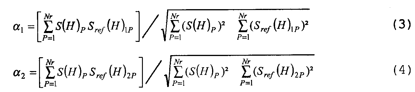
Затем, на этапе 76, если коэффициент α1 больше коэффициента α2, то магнитный материал, находящийся в резервуаре 8, идентифицируют как магнитный материал вида 1. Напротив, если коэффициент α1 меньше коэффициента α2, то магнитный материал, находящийся в резервуаре 8, идентифицируют как магнитный материал вида 2.Then, at
Следует отметить, что вычисление указанных коэффициентов корреляции между членами совокупности содержит поточечное умножение сигнатуры S(H) на сигнатуру Sref(H)1 или Sref(H)2. Указанная операция умножения созданной сигнатуры на опорную сигнатуру, полученную при измерении при идентичных условиях опорной массы идентичного магнитного материала, обеспечивает возможность весьма эффективного устранения шума, добавляемого к сигнатуре S(H). Следовательно, это существенно улучшает чувствительность способа анализа.It should be noted that the calculation of these correlation coefficients between members of the population contains pointwise multiplication of the signature S (H) by the signature S ref (H) 1 or S ref (H) 2 . The specified operation of multiplying the created signature by the reference signature obtained by measuring under identical conditions the reference mass of the same magnetic material, provides the ability to very effectively eliminate the noise added to the signature S (H). Therefore, this significantly improves the sensitivity of the analysis method.
Такое поточечное умножение здесь фигурирует в следующем выражении:Such pointwise multiplication appears here in the following expression:
![]()
![]()
Здесь предполагается, что на стадии 72 материал, который должен быть проанализирован, идентифицирован как материал вида 1.Here, it is assumed that in
Затем, блок 26 выполняет стадию 80 определения массы анализируемого магнитного материала.Then, block 26 performs
В начале стадии 80, на этапе 82, блок 26 определяет массу М магнитного материала в резервуаре 8 посредством выбора наибольшего из коэффициентов среди α1 и α2 и затем выполнения следующей операции (α1 является гипотезой)At the beginning of
![]()
![]()
гдеWhere
α1 представляет коэффициент корреляции между членами совокупности сигнатуры S(H) с сигнатурой Sref(H)1, полученной на этапе 72;α 1 represents the correlation coefficient between members of the population of signature S (H) with signature S ref (H) 1 obtained in
Mref1 представляет опорную массу, из которой была получена сигнатура Sref(H)1; иM ref1 represents the reference mass from which the signature S ref (H) 1 was obtained; and
М является массой анализируемого магнитного материала.M is the mass of the analyzed magnetic material.
Следовательно, преимущество можно получить из того свойства, что коэффициент корреляции между членами совокупности α1 прямо пропорционален отношению массы М к массе Mref1.Therefore, an advantage can be obtained from the property that the correlation coefficient between the members of the population α 1 is directly proportional to the ratio of mass M to mass M ref1 .
На фиг.5 представлена блок-схема способа анализа совокупности отличных магнитных материалов, который может быть выполнен в анализаторе 2. Здесь предполагается, что совокупность сформирована из смеси магнитных материалов вида 1 и вида 2.Figure 5 presents a flowchart of a method for analyzing a collection of excellent magnetic materials, which can be performed in the analyzer 2. Here it is assumed that the collection is formed from a mixture of magnetic materials of
Способ на фиг.5 идентичен способу на фиг.3 за исключением того, что стадии 72 и 80 заменены стадией 90 идентификации и одновременно определения массы каждого из магнитных материалов, находящихся в совокупности.The method of FIG. 5 is identical to the method of FIG. 3 except that steps 72 and 80 are replaced by a
В начале стадии 90, на этапе 92, блок 26 определяет коэффициенты корреляции между членами совокупности α1 и α2 посредством решения следующего матричного уравнения:At the beginning of
гдеWhere
S(H)j является j-й точкой сигнатуры S(H);S (H) j is the jth point of the signature S (H);
αi является отношением массы, которая должна быть измерена, магнитного материала, имеющего сигнатуру Sref(H)i, к опорной массе Mrefi, используемой для создания сигнатуры Sref(H)i;α i is the ratio of the mass to be measured, the magnetic material having the signature S ref (H) i , to the reference mass M refi used to create the signature S ref (H) i ;
Sref(H)ij является j-й точкой сигнатуры Sref(H)i;S ref (H) ij is the jth point of the signature S ref (H) i ;
N(H)j является j-й точкой сигнала, представляющего шум, добавляемый к измерению сигнатуры S(H); иN (H) j is the jth point of the signal representing the noise added to the measurement of the signature S (H); and
"Т" является символом функции транспонирования." T " is a symbol for the transpose function.
В указанном матричном уравнении (7) P представляет количество точек, содержащихся в сигнатуре S(H), при этом Q представляет количество опорных сигнатур. Соответственно, в определенном случае, описанном здесь, Q равно 2, и P равно Nr. На этапе 90 указанное матричное уравнение решают, например, с использованием псевдообратного способа. Этот способ дает следующее решение вышеупомянутого матричного уравнения:In said matrix equation (7), P represents the number of points contained in the signature S (H), while Q represents the number of reference signatures. Accordingly, in the specific case described here, Q is 2, and P is Nr. At
![]()
![]()
гдеWhere
![]()
![]()
S(H)1P является вектором [S(H)1, S(H)2,…, S(H)Р];S (H) 1P is the vector [S (H) 1 , S (H) 2 , ..., S (H) P ];
Sref(H)QP является матрицей размерности Q × P, фигурирующей в матричном уравнении (7);S ref (H) QP is a matrix of dimension Q × P, appearing in matrix equation (7);
"Т" является функцией транспонирования; и“ T ” is a transpose function; and
"-1" является обратной функцией." -1 " is the inverse function.
Затем, на этапе 94, определяют массу Mi каждого из магнитных материалов, находящихся в совокупности, содержащейся в резервуаре 8, согласно следующему уравнению:Then, at
![]()
![]()
гдеWhere
Mrefi является опорной массой, используемой для установления сигнатуры Sref(H)i магнитного материала вида i.M refi is the reference mass used to establish the signature S ref (H) i of a magnetic material of the form i.
Соответственно, последний способ имеет преимущество в обеспечении возможности анализа смеси из нескольких отличных магнитных материалов, и следовательно, смеси из нескольких биологических или химических компонентов, одновременно обеспечивая то, что присутствие каждого из биологических или химических компонентов выявляют посредством частиц магнитных материалов, отличных от тех, которые используют для выявления других биологических или химических компонентов, находящихся в этой же смеси.Accordingly, the latter method has the advantage of allowing analysis of a mixture of several different magnetic materials, and therefore a mixture of several biological or chemical components, while ensuring that the presence of each of the biological or chemical components is detected by particles of magnetic materials other than those which are used to identify other biological or chemical components in the same mixture.
В первом варианте осуществления выполняют магнитное концентрирование, сопровождаемое детектированием и/или количественным определением. Магнитное концентрирование или магнитное разделение является известной технологией, состоящей в концентрировании магнитных частиц в заданном объеме с использованием магнитных полей. Магнитный материал задействуют посредством лиганда, способного к связыванию биологического или химического состава, который должен быть сконцентрирован. Если компонентом является бактерия, то лигандом может быть антитело или любой другой лиганд, способный к определенному образованию связи с этой бактерией. Обычно используемыми лигандами являются антитела или биологические макромолекулы, такие как гормоны и фолиевая кислота.In a first embodiment, magnetic concentration is performed, followed by detection and / or quantification. Magnetic concentration or magnetic separation is a known technology consisting in the concentration of magnetic particles in a given volume using magnetic fields. The magnetic material is activated through a ligand capable of binding a biological or chemical composition that needs to be concentrated. If the component is a bacterium, then the ligand can be an antibody or any other ligand capable of a specific formation of bonds with this bacterium. Commonly used ligands are antibodies or biological macromolecules, such as hormones and folic acid.
Процессом магнитного концентрирования может быть периодический процесс, например, содержащий контакт магнита с резервуаром, содержащим образец, при этом магнит притягивает и удерживает магнитный материал и то, что с ним связано, для устранения жидкой среды и других компонентов, которые, возможно, присутствуют. Процесс магнитного концентрирования также может быть непрерывным и, например, содержит колонну или подобное устройство, через которое протекает жидкость, содержащая магнитный материал. Зона, охватываемая магнитным полем, называется зоной захвата. Указанная колонна или подобное устройство может содержать, по меньшей мере в этой зоне захвата, пористый материал. Магнитное поле индуцирует сильный градиент в зоне захвата. Затем может быть извлечен удержанный материал.The process of magnetic concentration can be a batch process, for example, containing contact of the magnet with the reservoir containing the sample, while the magnet attracts and holds the magnetic material and what is connected with it, to eliminate the liquid medium and other components that may be present. The magnetic concentration process can also be continuous and, for example, contains a column or similar device through which a fluid containing magnetic material flows. The area covered by the magnetic field is called the capture area. The specified column or similar device may contain, at least in this capture zone, a porous material. The magnetic field induces a strong gradient in the capture zone. The retained material can then be recovered.
Такая реализация изобретения с использованием магнитного концентрирования может, в частности, содержать:Such an implementation of the invention using magnetic concentration may, in particular, contain:
первый вид магнитного материала, к которому присоединен лиганд, способный к образованию связи с биологическим или химическим компонентом, который должен быть задетектирован;a first type of magnetic material to which a ligand is attached, capable of forming a bond with a biological or chemical component that must be detected;
образец, который должен быть проанализирован, смешивается с магнитным материалом, создавая комплекс магнитных материалов/компонентов;the sample to be analyzed is mixed with magnetic material, creating a complex of magnetic materials / components;
магнитное концентрирование магнитного комплекса, например, с использованием непрерывного или группового способа, как описано выше;magnetic concentration of the magnetic complex, for example, using a continuous or group method, as described above;
затем комплекс приводится в контакт с другим магнитным материалом, второго вида, к которому присоединен лиганд, также способный к образованию связи с находящимся в магнитном материале первого вида биологическим или химическим компонентом, который должен быть задетектирован, или к образованию связи с реагентом, обеспечивающим возможность детектирования или количественного определения указанного компонента; иthen the complex is brought into contact with another magnetic material, of the second type, to which a ligand is attached, also capable of forming a bond with the biological or chemical component that is to be detected in the magnetic material of the first type, or with the formation of a bond with a reagent that allows detection or quantifying said component; and
анализ магнитных материалов для вывода из этого массы магнитного материала второго вида и для вывода из этого наличия или количества биологического или химического компонента в первоначальном образце.analysis of magnetic materials for the derivation of a second type of magnetic material from this mass and for the derivation from this presence or quantity of a biological or chemical component in the original sample.
Во втором способе реализации изобретения осуществляют детектирование и/или количественное определение двух или большего количества биологических или химических компонентов в одном образце, для чегоIn a second embodiment of the invention, two or more biological or chemical components are detected and quantified in one sample, for which
используют первый вид магнитного материала, который образует связь с первым биологическим или химическим компонентом или с реагентом, обеспечивающим возможность детектирования и/или количественного определения указанного компонента; иusing the first type of magnetic material, which forms a bond with the first biological or chemical component or with a reagent that enables the detection and / or quantification of the specified component; and
используют по меньшей мере одного другого, например, второго, другого вида магнитный материал, который образует связь с другим, например вторым биологическим или химическим компонентом или с реагентом, обеспечивающим возможность детектирования и/или количественного определения указанного компонента,using at least one other, for example, a second, different type of magnetic material, which forms a bond with another, for example, a second biological or chemical component or with a reagent that allows the detection and / or quantification of the specified component,
реализация изобретения обеспечивает возможность детектирования и/или количественного определения каждого из указанных биологических или химических компонентов в отдельности.the implementation of the invention provides the ability to detect and / or quantify each of these biological or chemical components separately.
Соответственно, этот способ реализации может обеспечивать возможность анализа биологического образца для поиска и, опционально, количественного определения нескольких антигенов любого одного микроорганизма или нескольких микроорганизмов (отличной природы или отличного вида одного микроорганизма, например, отличных серотипов одного микроорганизма, например вируса). Также возможно одновременно анализировать компоненты отличной природы, например антитело и антиген.Accordingly, this implementation method can provide an opportunity to analyze a biological sample to search and, optionally, quantify several antigens of any one microorganism or several microorganisms (of excellent nature or a different kind of one microorganism, for example, excellent serotypes of one microorganism, for example a virus). It is also possible to simultaneously analyze components of excellent nature, such as an antibody and antigen.
В третьем способе реализации, который может быть объединен с двумя предыдущими, осуществляют количественное определение по меньшей мере одного биологического или химического компонента в образце с использованием первого вида магнитного материала при наличии второго, отличного, вида магнитного материала, при этомIn the third implementation method, which can be combined with the two previous ones, the at least one biological or chemical component in the sample is quantified using the first type of magnetic material in the presence of a second, different, type of magnetic material,
используют первый вид магнитного материала, который образует связь с биологическим или химическим компонентом, количество которого должно быть определено, или с реагентом, обеспечивающим возможность детектирования и/или количественного определения указанного компонента; иusing the first type of magnetic material, which forms a bond with a biological or chemical component, the amount of which must be determined, or with a reagent that allows the detection and / or quantification of the specified component; and
используют второй вид магнитного материала, который является инертным по отношению к вышеупомянутому компоненту и, предпочтительно, инертным по отношению к любому находящемуся в образце компоненту,using a second type of magnetic material that is inert to the aforementioned component and preferably inert to any component in the sample,
реализация изобретения обеспечивает возможность количественного определения масс каждого из видов магнитного материала в зоне реакции в отдельности.the implementation of the invention provides the possibility of quantitative determination of the masses of each type of magnetic material in the reaction zone separately.
Согласно одному признаку изобретения, второй вид магнитного материала служит в качестве внутреннего эталона, обеспечивающего возможность учета условий, при которых проводят испытание, например, характеристик диффузии внутри или на пористом материале. Это обеспечивает возможность учета условий испытания, так чтобы корректировать преобразование массы первого магнитного материала, измеренной в зоне реакции, в количество компонента в образце и выдавать количественный результат, независимый от условий, при которых проводили испытание. Например, это делает возможным компенсацию воздействий изменений в диффузии от одного образца к другому. Для этого определяют полную первоначальную массу внутреннего эталона и сравнивают массу, измеренную в зоне реакции, с этой полной массой, создавая отношение масс.According to one feature of the invention, the second type of magnetic material serves as an internal reference, allowing for the consideration of the conditions under which the test is carried out, for example, diffusion characteristics inside or on a porous material. This makes it possible to take into account the test conditions, so as to adjust the conversion of the mass of the first magnetic material, measured in the reaction zone, into the amount of the component in the sample and give a quantitative result, independent of the conditions under which the test was performed. For example, this makes it possible to compensate for the effects of changes in diffusion from one sample to another. To do this, determine the total initial mass of the internal standard and compare the mass measured in the reaction zone with this total mass, creating a mass ratio.
Этап анализа различных способов реализации может быть выполнен обычным образом, после диффузии комплекса в или на пористой опоре (например, полоске или миниатюрной колонне) и определенного удержания комплексов в зоне снятия показаний. Этот способ может быть применен также для концентрирования и детектирования двух или большего количества компонентов. Способ, согласно изобретению, используют в областях диагностики и для поиска загрязняющих веществ. Изучаемыми образцами являются образцы, обычно изучаемые в этих областях. Они могут быть получены из жидкостей тела, например крови, плазмы или мочи, или могут возникать в результате соответствующей обработки ткани. Искомыми компонентами, в частности, могут быть антигены (микроорганизмы, например, бактерии, вирусы, одноклеточные грибы, дрожжи, паразиты или их фракции), антитела или любые другие биологические компоненты, такие как гаптены, белки, природные или синтетические олигонуклеотиды или полинуклеотиды, природные или синтетические моносахариды, олигосахариды или полисахариды, лектины, авидин, стрептавидин, биотин, факторы роста, гормоны, рецепторы и аллергены. Изобретение также пригодно для поиска и количественного определения химических сущностей или компонентов, таких как антибиотики, наркотики, химические загрязняющие вещества и аллергены.The stage of analysis of various implementation methods can be carried out in the usual way, after diffusion of the complex in or on a porous support (for example, a strip or a miniature column) and a certain retention of the complexes in the reading zone. This method can also be used to concentrate and detect two or more components. The method according to the invention is used in the fields of diagnostics and for the search for pollutants. Samples studied are samples commonly studied in these areas. They can be obtained from body fluids, such as blood, plasma or urine, or can result from appropriate tissue treatment. The desired components, in particular, can be antigens (microorganisms, for example, bacteria, viruses, unicellular fungi, yeast, parasites or their fractions), antibodies or any other biological components, such as haptens, proteins, natural or synthetic oligonucleotides or polynucleotides, natural or synthetic monosaccharides, oligosaccharides or polysaccharides, lectins, avidin, streptavidin, biotin, growth factors, hormones, receptors and allergens. The invention is also suitable for searching and quantifying chemical entities or components such as antibiotics, drugs, chemical contaminants and allergens.
Возможные варианты магнитных материалов, которые могут быть использованы в такой реализации, могут содержать вышеупомянутые SeraMag® и MagPrep®.Possible magnetic materials that may be used in such an implementation may include the aforementioned SeraMag® and MagPrep®.
Возможны многие другие варианты осуществления. Например, количество магнитных материалов, которые могут быть идентифицированы или проанализированы одновременно, может быть увеличено посредством увеличения количества опорных сигнатур, содержащихся в памяти 28. Как вариант, размер памяти 28 может быть уменьшен в случае, в котором она содержит только одну сигнатуру, если материал, который должен быть проанализирован, всегда один и тот же.Many other embodiments are possible. For example, the number of magnetic materials that can be identified or analyzed at the same time can be increased by increasing the number of reference signatures contained in the memory 28. Alternatively, the size of the memory 28 can be reduced in the case in which it contains only one signature, if the material which must be analyzed is always the same.
Здесь, сигнатуры были созданы посредством измерения амплитуды гармоники частоты 2fH. Как вариант, то, что было описано, также применяется к сигнатуре, созданной посредством измерения амплитуды гармоники частоты nfH, где n является целым числом, равным или большим 1. Однако, предпочтительно, n должно быть строго больше 1, и предпочтительно, n должно быть четным. Это так, потому что четное число обеспечивает возможность дополнительного повышения чувствительности по сравнению со случаем, в котором n является нечетным.Here, signatures were created by measuring the harmonic amplitude of a frequency of 2f H. Alternatively, what has been described also applies to the signature created by measuring the harmonic amplitude of the frequency nf H , where n is an integer equal to or greater than 1. However, preferably, n should be strictly greater than 1, and preferably, n should to be even. This is because an even number provides the possibility of an additional increase in sensitivity compared to the case in which n is odd.
Используемый магнитный материал может быть любого соответствующего вида и проявляет нелинейную характеристику намагничивания.The magnetic material used may be of any appropriate kind and exhibits a non-linear magnetization characteristic.
Например, обычно магнитные частицы могут быть размером приблизительно от 5 нм до 50 мкм, предпочтительно приблизительно от 10 нм до 10 мкм, более предпочтительно приблизительно от 100 нм до 1 мкм. Частицы могут иметь сферическую или овальную форму, или любую другую форму. Частицы могут быть выполнены непосредственно из магнитного материала или из смеси этого материала с твердой или полутвердой матрицей. В последнем случае магнитный материал рассредоточен в матрице.For example, typically magnetic particles can be in the size range of from about 5 nm to about 50 μm, preferably from about 10 nm to about 10 μm, more preferably from about 100 nm to 1 μm. Particles can have a spherical or oval shape, or any other shape. Particles can be made directly from a magnetic material or from a mixture of this material with a solid or semi-solid matrix. In the latter case, the magnetic material is dispersed in the matrix.
В варианте осуществления частицы являются суперпарамагнитными. Согласно признаку, эти частицы выполнены из ферромагнитных элементов в матрице, и максимальный размер ферромагнитных элементов является достаточно малым для того, чтобы каждый элемент, взятый в отдельности, имел цикл намагничивания B(H), имеющий свойства, идентичные представленным на фиг.8. Обычно максимальный размер ферромагнитного элемента выбирают так, чтобы он был приблизительно меньше 100 нм и, в основном, приблизительно меньше 20 нм. Этот максимальный размер элемента, при уменьшении которого элемент становится суперпарамагнитным, зависит от используемого ферромагнитного материала. Суперпарамагнетизм, также как суперпарамагнитные элементы, представлен в работе Е. дю Тремолете де Лахейсьере (E. du Tremolet de Lacheisserie) и другие "Magnetisme", ТОМ 1, напечатанной Университетом Гренобля, 1999.In an embodiment, the particles are superparamagnetic. According to the characteristic, these particles are made of ferromagnetic elements in the matrix, and the maximum size of the ferromagnetic elements is small enough so that each individual element has a magnetization cycle B (H) having properties identical to those shown in Fig. 8. Typically, the maximum size of the ferromagnetic element is chosen so that it is approximately less than 100 nm and, basically, approximately less than 20 nm. This maximum element size, upon reduction of which the element becomes superparamagnetic, depends on the ferromagnetic material used. Superparamagnetism, as well as superparamagnetic elements, is presented by E. du Tremolet de Lacheisserie and others, "Magnetisme",
Предпочтительными суперпарамагнитными элементами являются оксиды железа. Более полно определено, что элемент может быть выбран среди оксидов железа и смешанных оксидов железа и другого металла, при этом в предпочтительных вариантах осуществления металл выбирают из группы, состоящей из Mn, Ni, Zn, Bi, Cu, Fe3O4 и Fe2O3. Другие возможные варианты включают в себя: первоскиты с суперпарамагнитными свойствами, в частности, первоскиты на основе Fe; суперпарамагнитные оксиды никеля, оксиды кобальта или смешанные оксиды указанных металлов; а также суперпарамагнитные металлические сплавы, например вида FeNi или CoNi, в частности Fe20Ni80.Preferred superparamagnetic elements are iron oxides. It is more fully determined that the element can be selected among iron oxides and mixed oxides of iron and another metal, and in preferred embodiments, the metal is selected from the group consisting of Mn, Ni, Zn, Bi, Cu, Fe 3 O 4 and Fe 2 O 3 . Other possible options include: novoscites with superparamagnetic properties, in particular, Fe-based novoskits; superparamagnetic nickel oxides, cobalt oxides or mixed oxides of these metals; as well as superparamagnetic metal alloys, for example, FeNi or CoNi, in particular Fe 20 Ni 80 .
В другом варианте осуществления частицами является антиферромагнетик. Антиферромагнитный материал является материалом, где спины магнитных электронов выровнены по правильной модели с соседними спинами, ориентированными в антипараллельных направлениях. Такой материал содержит металлы, такие как хром, сплавы, такие как FeMn, оксиды, такие как NiO. Ссылка может быть сделана также на вышеупомянутую (работу) Е. дю Тремолете де Лахейсьере и другие.In another embodiment, the particles are an antiferromagnet. An antiferromagnetic material is a material where the spins of magnetic electrons are aligned according to the correct model with neighboring spins oriented in antiparallel directions. Such a material contains metals such as chromium, alloys such as FeMn, oxides such as NiO. Reference can also be made to the aforementioned (work) E. du Tremolete de Lacheisere and others.
Выбирают твердую или полутвердую матрицу, так чтобы отсутствовало воздействие на магнитные свойства элемента. Согласно признаку, матрицей является диамагнетик.A solid or semi-solid matrix is chosen so that there is no effect on the magnetic properties of the element. According to the sign, the matrix is a diamagnet.
Полутвердая матрица содержит матрицу, которая является упруго деформируемой обратимым образом, например эластомер.A semi-solid matrix contains a matrix that is elastically deformable in a reversible manner, for example an elastomer.
Материалы для матрицы содержат: природные, синтетические и искусственные полимеры, эластомеры и гели, кварц, например пластмассу, целлюлозный материал.Materials for the matrix contain: natural, synthetic and artificial polymers, elastomers and gels, quartz, for example plastic, cellulosic material.
Распределение суперпарамагнитных элементов в матрице является таким, что расстояния между элементами внутри матрицы являются достаточными для того, чтобы сформированные таким образом частицы имели суперпарамагнитные свойства идентичные или по существу идентичные суперпарамагнитным свойствам элемента.The distribution of the superparamagnetic elements in the matrix is such that the distances between the elements within the matrix are sufficient so that the particles thus formed have superparamagnetic properties identical or substantially identical to the superparamagnetic properties of the element.
Согласно другому признаку, матрица обеспечивает возможность достаточной близости или достаточной подвижности магнитных элементов, содержащихся в каждой частице, для совместного магнитного взаимодействия. Это взаимодействие может немного воздействовать на сигнатуру частицы в целом, сформированной магнитными элементами, содержащимися в матрице, делая ее отличной от сигнатуры отдельных магнитных элементов. Это явление формирует других кандидатов для мультиплексирования.According to another feature, the matrix provides the possibility of sufficient proximity or sufficient mobility of the magnetic elements contained in each particle for joint magnetic interaction. This interaction can slightly affect the signature of the particle as a whole, formed by the magnetic elements contained in the matrix, making it different from the signature of individual magnetic elements. This phenomenon forms other candidates for multiplexing.
Однако, как вариант, может быть использован любой вид магнитного материала. В частности, магнитный материал может проявлять гистерезис или остаточную намагниченность. Например, магнитным материалом может быть ферромагнитный или антиферромагнитный материал.However, as an option, any kind of magnetic material can be used. In particular, the magnetic material may exhibit hysteresis or residual magnetization. For example, the magnetic material may be a ferromagnetic or antiferromagnetic material.
Изобретение также обеспечивает использование шаблона наноструктур, который несет и/или содержит магнитные частицы.The invention also provides the use of a nanostructure template that carries and / or contains magnetic particles.
В последующем описании будет упомянуто несколько публикаций, в которых описываются продукты и способы создания того, что составляет возможные варианты для выполнения изобретения. Полное содержание указанных публикаций включено здесь в качестве ссылки, и специалист в данной области техники может использовать описанные здесь способы для реализации настоящего изобретения.In the following description, several publications will be mentioned in which products and methods for creating what constitutes possible embodiments of the invention are described. The full contents of these publications are incorporated herein by reference, and a person skilled in the art can use the methods described herein to implement the present invention.
Наноструктуры имеют предварительно определенную форму. Они могут быть выбраны, в частности, среди: нанотрубок, нанопроводов, наноколец, нанодисков, нанопружин. Наноструктура может быть линейной или нелинейной, открытой или замкнутой, двухмерной или трехмерной. Предполагается, что наноструктура обнаруживает магнитную сигнатуру, которая является особенной по своей форме и своему размеру и природе, количеству и распределению магнитного материала на поверхности и/или внутри наноструктуры. Изменение указанных факторов обеспечивает возможность получения специалистом в данной области техники соответствующих отличных магнитных сигнатур. Наноструктуры могут иметь размер от 50 нм до более чем 10 мкм.Nanostructures have a predefined shape. They can be selected, in particular, among: nanotubes, nanowires, nanorings, nanodisks, nanosprings. The nanostructure can be linear or nonlinear, open or closed, two-dimensional or three-dimensional. It is assumed that the nanostructure detects a magnetic signature, which is special in its shape and size and nature, the amount and distribution of magnetic material on the surface and / or inside the nanostructure. Changing these factors makes it possible for a person skilled in the art to obtain corresponding excellent magnetic signatures. Nanostructures can have a size from 50 nm to more than 10 microns.
Наноструктуры могут быть созданы из различных материалов, они могут быть металлическими, такими как углерод или медь, сделанными из двуокиси циркония, или могут быть пептическими, то есть сделанными из пептида, или содержащими пептид, в основном, из обогащенных гистидином молекул пептида, или липидных или гетеролипидных, или комбинации вышеупомянутых макромолекул.Nanostructures can be created from various materials, they can be metallic, such as carbon or copper, made from zirconia, or can be peptic, that is, made from a peptide, or containing a peptide, mainly from histidine-enriched peptide molecules, or lipid or heterolipidic, or a combination of the above macromolecules.
Наноструктуры пептида, такие как нанотрубки, созданные посредством самосборки пептидов, были описаны в работе С. Занг (S. Zhang) и другие, Current Opinion in Chemical Biology, 2002, 6:865-871; и М. Ричиз (М. Reches) и Е. Газит (E. Gazit), Current Nanoscience, 2006, 2:105-111.Peptide nanostructures, such as nanotubes created by self-assembly of peptides, have been described by S. Zhang et al., Current Opinion in Chemical Biology, 2002, 6: 865-871; and M. Richies (M. Reches) and E. Gazit (E. Gazit), Current Nanoscience, 2006, 2: 105-111.
Нанотрубки двуокиси циркония, заключающие в себе нанопровода металла, были описаны в (работе) Д. Бао (J. Bao) и другие, Chem. Mater. 2002, 14:4709-4713. Процедура для подготовки указанных нанотрубок может быть использована здесь для создания магнитных нанотрубок посредством замены электролита CuSO4/H3BO3 на электролит, содержащий FeCl3, 6H2O и NaBH4 (например, 20g/L, соответственно 50 g/L).Zirconia nanotubes containing metal nanowires have been described by J. Bao et al., Chem. Mater. 2002, 14: 4709-4713. The procedure for preparing these nanotubes can be used here to create magnetic nanotubes by replacing the CuSO 4 / H 3 BO 3 electrolyte with an electrolyte containing FeCl 3 , 6H 2 O and NaBH 4 (for example, 20g / L, respectively 50 g / L).
Другим вариантом осуществления является использование металлических наноструктур, покрытых пептидами, таких, как описаны в И.А. Банерджи (I. A. Banerjee), PNAS 2003, 100, 25:14678-14682. В этой публикации описан рост нанокристалла Cu на пептидных нанотрубках. Этот процесс может быть модифицирован для замены Cu на Fe. Fe может быть внесен, например, с использованием соли триметил-фосфин-хлоро-железа.Another embodiment is the use of metal nanostructures coated with peptides, such as those described in IA Banerjee (I. A. Banerjee), PNAS 2003, 100, 25: 14678-14682. This publication describes the growth of Cu nanocrystal on peptide nanotubes. This process can be modified to replace Cu with Fe. Fe can be introduced, for example, using a salt of trimethyl-phosphine-chloro-iron.
Когда наноструктура должна использоваться в совокупности, согласно изобретению, когда требуется ее детектирование, например, в способе диагностики, то может быть задействована наноструктура, содержащая наноструктуры, покрытые пептидом, для представления части лиганда, например, антитело или антиген, или нуклеиновый зонд, или любой подходящий химический компонент, такой как биотин.When a nanostructure is to be used in conjunction according to the invention, when it is required to be detected, for example, in a diagnostic method, a nanostructure containing peptide coated nanostructures can be used to represent part of the ligand, for example, an antibody or antigen, or a nucleic probe, or any a suitable chemical component, such as biotin.
В работе З. Жао (Z. Zhao) и другие, J. Chem. Soc, 2005, 127: 8939-8931, описан способ покрытия наноструктур антителами, в частности, IgG.In the work of Z. Zhao (Z. Zhao) and others, J. Chem. Soc, 2005, 127: 8939-8931, a method for coating nanostructures with antibodies, in particular IgG, is described.
Магнитными "частицами" могут быть также магнитосомы или скопления или совокупности магнитосомов. Магнитосомами являются гранулы металлических оксидов, созданные бактериями, обнаруживающими магнитотаксис. Они сформированы из нанокристаллов, в частности монокристаллических, и в основном, окруженных липидной биомембраной. В основном, кристаллы имеют размер, варьирующийся от 35 до 120 нм. В основном, они выполнены из магнетита Fe3O4 и иногда грейгита Fe3S4. Предпочтительным вариантом осуществления являются магнитосомы магнитита.Magnetic “particles” can also be magnetosomes or clusters or sets of magnetosomes. Magnetosomes are granules of metal oxides created by bacteria that detect magnetotaxis. They are formed of nanocrystals, in particular monocrystalline and substantially surrounded by lipid biological membrane. In general, crystals have a size ranging from 35 to 120 nm. Basically, they are made of magnetite Fe 3 O 4 and sometimes greigite Fe 3 S 4 . A preferred embodiment are magnetosomes of magnetite.
Магнитосомы могут быть созданы посредством выращивания бактерии, обнаруживающей магнитотаксис, и извлечения магнитосомов. Одним возможным вариантом является выращивание Magnetospirillum magneticum, например, линияMagnetosomes can be created by growing a magnetotaxis-detecting bacterium and extracting the magnetosomes. One possible option is to grow Magnetospirillum magneticum, for example, a line
AMB-1. Способ выращивания этих бактерий и извлечения магнитосомов был описан в И.А. Бенерджи (I. A. Banerjee) и другие, Adv. Mater., 2005, 17: 1128-1131. Бактерии растут анаэробно в ферментере, культуру собирают центрифугированием, останавливают (процесс) и извлекают магнитосомы с использованием магнита.AMB-1. A method for growing these bacteria and extracting magnetosomes was described in I.A. Benerjee (I. A. Banerjee) and others, Adv. Mater., 2005, 17: 1128-1131. Bacteria grow anaerobically in the fermenter, the culture is collected by centrifugation, stopped (process) and magnetosomes are removed using a magnet.
В предпочтительном варианте осуществления, магнитосомы содержатся в наноструктуре или присоединены к поверхности наноструктуры, как описано выше. Также возможно присоединение магнитосомов к поверхности и включение внутрь наноструктуры. Как описано выше, наноструктуры имеют предварительно определенную форму, выбранную, в частности, среди: нанотрубок, нанопроводов, наноколец, нанодисков, нанопружин. Наноструктура может быть линейной или нелинейной, открытой или замкнутой, двухмерной или трехмерной.In a preferred embodiment, the magnetosomes are contained in the nanostructure or attached to the surface of the nanostructure, as described above. It is also possible to attach magnetosomes to the surface and incorporate the nanostructure inside. As described above, nanostructures have a predefined shape, selected, in particular, among: nanotubes, nanowires, nanorings, nanodisks, nanosprings. The nanostructure can be linear or nonlinear, open or closed, two-dimensional or three-dimensional.
Возможный вариант такой наноструктуры описан в Банерджи (Banerjee) 2005. В этой публикации описано объединение магнитосомов в нанотрубки. Это является возможным вариантом магнитной наноструктуры, используемой в изобретении.A possible variant of such a nanostructure is described in Banerjee 2005. This publication describes the integration of magnetosomes into nanotubes. This is a possible variant of the magnetic nanostructure used in the invention.
То, что здесь было описано, также применимо для идентификации и измерения массы твердого блока магнитных материалов.What has been described here is also applicable for identifying and measuring the mass of a solid block of magnetic materials.
В одном варианте осуществления изобретения для избирательной сортировки материалов, например пластмасс различных видов, в массе которых рассредоточены магнитные материалы, согласно изобретению. Следовательно, материалы, которые должны быть разделены, вначале содержат магнитный материал отличного вида. Например, пакет PVC содержит первый вид магнитного материала, при этом пакет полиэстера содержит второй вид магнитного материала и так далее. Посредством детектирования сигнатуры данного материала, возможно определять материал, например пакет, и вручную или механически отделять его от других присутствующих материалов.In one embodiment of the invention, for selectively sorting materials, for example plastics of various kinds, in the mass of which magnetic materials are dispersed, according to the invention. Therefore, the materials to be separated first contain excellent magnetic material. For example, a PVC bag contains a first type of magnetic material, while a polyester bag contains a second type of magnetic material and so on. By detecting the signature of a given material, it is possible to determine a material, such as a bag, and manually or mechanically separate it from other materials present.
Если в течение фазы калибровки отношение сигнала к шуму является достаточно высоким, то опорная сигнатура может быть измерена только по двум периодам TL, по этим измерениям существует возможность создания опорной сигнатуры по большему количеству периодов.If during the calibration phase the signal-to-noise ratio is high enough, then the reference signature can be measured only by two periods T L , from these measurements it is possible to create a reference signature from a larger number of periods.
Если форма сигнатуры Sref(H)i уже известна, то в течение фазы калибровки может быть достаточно одного измерения для создания сигнатуры, содержащей несколько точек.If the shape of the signature S ref (H) i is already known, then during the calibration phase one measurement may be sufficient to create a signature containing several points.
Здесь был описан способ анализа в определенном случае, в котором измерения точек каждой сигнатуры Sref(H)i и S(H) делают для идентичных мгновенных значений HLi напряженности магнитного поля HL. Как вариант, значения HLi, используемые для создания сигнатуры Sref(H)i, могут быть отличны от значений HLi, используемых для создания сигнатуры S(H). В этом случае, существует возможность создания отсутствующих точек сигнатуры Sref(H)i, соответствующих точкам сигнатуры S(H), посредством интерполяции.Here, a specific analysis method has been described in which measurements of the points of each signature S ref (H) i and S (H) are made for identical instantaneous values H Li of the magnetic field strength H L. Alternatively, the H Li values used to create the signature S ref (H) i may be different from the H Li values used to create the signature S ref (H) i . In this case, it is possible to create missing points of signature S ref (H) i corresponding to points of signature S (H) by interpolation.
Как вариант, существует возможность создания отличных сигнатур для одного магнитного материала. Например, первую сигнатуру создают с использованием амплитуды и фазы гармоники xfH. Вторую сигнатуру для этого материала создают с использованием амплитуды и фазы гармоники yfH, где x и y являются ненулевыми целыми числами, отличными друг от друга, и предпочтительно, не меньшими 2. Затем, при измерении неизвестной массы этого магнитного материала могут быть использованы две указанные сигнатуры, последовательно или одновременно. Если сигнатуры используются одновременно, то предполагается, что конструктор выполнен с возможностью одновременного извлечения амплитуд гармоник частот xfH и yfH. Затем, отличные промежуточные массы, полученные с использованием отличных сигнатур, объединяют для получения измеренной массы магнитного материала. Например, отличные промежуточные массы усредняют.Alternatively, it is possible to create excellent signatures for a single magnetic material. For example, a first signature is created using the amplitude and phase of the harmonic xf H. The second signature for this material is created using the amplitude and phase of the harmonic yf H , where x and y are nonzero integers that are different from each other, and preferably not less than 2. Then, when measuring the unknown mass of this magnetic material, two indicated signatures, sequentially or simultaneously. If the signatures are used simultaneously, it is assumed that the constructor is capable of simultaneously extracting the harmonics of the frequencies xf H and yf H. Then, excellent intermediate masses obtained using excellent signatures are combined to obtain a measured mass of magnetic material. For example, excellent intermediate masses average.
Анализируемый магнитный материал может быть идентифицирован просто посредством сравнения каждого коэффициента корреляции между членами совокупности αi, вычисленного при предварительно определенном пороге.The analyzed magnetic material can be identified simply by comparing each correlation coefficient between members of the population α i calculated at a predetermined threshold.
В определенном случае, в котором полностью отсутствует корреляция сигнатур Sref(H)i, то есть коэффициент β корреляции между членами совокупности для двух сигнатур Sref(H)i и Sref(H)j меньше 0,1, существует возможность использования способа по фиг.3 для определения массы каждого магнитного материала в совокупности отличных магнитных материалов. Для этого способ по фиг.3 повторяют для каждого вида искомого магнитного материала, каждый раз изменяя опорную сигнатуру.In a certain case, in which there is completely no correlation of the signatures S ref (H) i , that is, the correlation coefficient β between the members of the population for two signatures S ref (H) i and S ref (H) j is less than 0.1, there is the possibility of using the method figure 3 to determine the mass of each magnetic material in the aggregate of excellent magnetic materials. For this, the method of FIG. 3 is repeated for each type of magnetic material sought, each time changing the reference signature.
Если существует корреляция различных опорных сигнатур, то также существует возможность использования способа по фиг.3 для определения массы каждого из магнитных материалов совокупности отличных магнитных материалов. Например, если магнитным материалом является смесь магнитных материалов вида 1 и вида 2, то выполнение способа по фиг.3 с использованием опорной сигнатуры Sref(H)1, затем сигнатуры Sref(H)2, эквивалентно следующей системе уравнений:If there is a correlation of various reference signatures, then there is also the possibility of using the method of FIG. 3 to determine the mass of each of the magnetic materials of a combination of excellent magnetic materials. For example, if the magnetic material is a mixture of magnetic materials of
![]()
![]()
гдеWhere
αm1 и αm2 являются результатами, полученными при применении уравнений (3) и (4), соответственно;α m1 and α m2 are the results obtained by applying equations (3) and (4), respectively;
α1 и α2 эквивалентны ![]()
![]()
![]()
![]()
β является коэффициентом корреляции между членами совокупности для опорных сигнатур Sref(H)1 и Sref(H)2.β is the correlation coefficient between the members of the population for the reference signatures S ref (H) 1 and S ref (H) 2 .
Уравнение (10) позволяет определить коэффициенты α1 и α2 и, следовательно, массы M1 и M2.Equation (10) allows you to determine the coefficients α 1 and α 2 and, therefore, the masses M 1 and M 2 .
Как вариант, этап 80 способа по фиг.3 может быть опущен. В этом случае способ анализа делает возможным только идентификацию, какого вида материал находится в резервуаре 8.Alternatively, step 80 of the method of FIG. 3 may be omitted. In this case, the analysis method makes it possible only to identify what type of material is in the tank 8.
Напротив, если заранее известен вид магнитного материала, находящегося в резервуаре 8, то может быть опущена стадия 72 идентификации. В этом варианте вычисление коэффициента αi корреляции между членами совокупности между сигнатурой S(H) и опорной сигнатурой Sref(H)i должно быть выполнено в течение стадии 80 перед этапом 82. В этом варианте количество r участков периода может быть уменьшено до двух.On the contrary, if the type of magnetic material located in the reservoir 8 is known in advance, the
Способы по фиг.3 и по фиг.5 были описаны для определенного случая, в котором при вычислении коэффициента корреляции между членами совокупности αi поточечно умножают сигнатуры S(H) и Sref(H)i. Однако, как вариант, сигнатуры S(H) и Sref(H)i могут быть умножены поточечно на третью опорную сигнатуру Sref(H)K. В этом случае массу M1 магнитного материала вида 1, находящегося в резервуаре 8, вычисляют с использованием следующих уравнений:The methods of FIG. 3 and FIG. 5 have been described for a specific case in which, when calculating the correlation coefficient between members of the population α i, the signatures S (H) and S ref (H) i are multiplied pointwise. However, as an option, the signatures S (H) and S ref (H) i can be multiplied pointwise by the third reference signature S ref (H) K. In this case, the mass M 1 of the magnetic material of

гдеWhere
β1 является коэффициентом корреляции между членами совокупности между опорной сигнатурой Sref(H)1 магнитного материала вида 1 и опорной сигнатурой Sref(H)K; иβ 1 is the correlation coefficient between members of the population between the reference signature S ref (H) 1 of the magnetic material of
α1 является коэффициентом корреляции между членами совокупности между измеренной сигнатурой S(H) и опорной сигнатурой Sref(H)K.α 1 is the correlation coefficient between the members of the population between the measured signature S (H) and the reference signature S ref (H) K.
Сигнатурой Sref(H)K может быть сигнатура, измеренная на магнитном материале, отличном от магнитного материала вида 1. Сигнатурой Sref(H)K может быть также любая сигнатура, выбранная разработчиками анализатора 2.The signature S ref (H) K can be a signature measured on magnetic material other than magnetic material of
Например, сигнатурой Sref(H)K может быть последовательность псевдослучайных точек. Этот вариант, следовательно, обеспечивает возможность записи только одной опорной сигнатуры Sref(H)K. Однако память 28 должна содержать также коэффициент корреляции между членами совокупности βi между каждой опорной сигнатурой Sref(H)i и указанной сигнатурой Sref(H)K.For example, the signature S ref (H) K may be a sequence of pseudo-random points. This option, therefore, provides the ability to record only one reference signature S ref (H) K. However, the memory 28 must also contain a correlation coefficient between members of the population β i between each reference signature S ref (H) i and the specified signature S ref (H) K.
В другом варианте осуществления, может быть использовано несколько опорных сигнатур, полученных для отличных опорных масс идентичного магнитного материала. Например, предполагается, что сигнатура Sref(H)K, описанная согласно уравнениям (11) и (12), используется в качестве опорной сигнатуры. Для опорных масс Mref11 и Mref12 магнитного материала вида 1 уравнение (11) дает результаты β11 и β12. Также предполагается, что уравнение (12) дает результат α1, находящийся между β11 и β12. Тогда масса M1 материала вида 1 в резервуаре 8 может быть вычислена с использованием следующего уравнения:In another embodiment, several reference signatures obtained for excellent reference masses of the same magnetic material can be used. For example, it is assumed that the signature S ref (H) K described in accordance with equations (11) and (12) is used as a reference signature. For the reference masses M ref11 and M ref12 of a magnetic material of
![]()
![]()
Следовательно, массу M1 получают посредством линейной интреполяции между массами Mref1 и Mref2. Следовательно, должно быть понятно, что использование нескольких сигнатур для одного магнитного материала обеспечивает возможность повышения точности, в частности, если уравнение между массой M1 и коэффициентом α1 не является линейным.Therefore, mass M 1 is obtained by linear interpolation between masses M ref1 and M ref2 . Therefore, it should be understood that the use of several signatures for the same magnetic material provides the possibility of increasing accuracy, in particular, if the equation between the mass M 1 and the coefficient α 1 is not linear.
Анализатор 2 был описан в определенном случае, в котором напряженность магнитного поля HL является постоянной в каждом из промежутков TP. Как вариант, мгновенное значение (напряженности) магнитного поля HL не является постоянным за каждый из промежутков TP. Однако средние значения мгновенного значения (напряженности) магнитного поля HL за каждый из промежутков TP отличны друг от друга. Например, как изображено на фиг.6, мгновенное значение (напряженности) магнитного поля HL, как функции от времени, может быть синусоидальным. Может быть подтверждено, что среднее значение мгновенного значения за промежуток Ti, действительно, отлично от среднего значения мгновенного значения за промежуток T2.Analyzer 2 has been described in a specific case in which the magnetic field strength H L is constant in each of the gaps T P. Alternatively, the instantaneous value (intensity) of the magnetic field H L is not constant for each of the gaps T P. However, the average values of the instantaneous value (intensity) of the magnetic field H L for each of the intervals T P are different from each other. For example, as shown in Fig.6, the instantaneous value (intensity) of the magnetic field H L , as a function of time, can be sinusoidal. It can be confirmed that the average value of the instantaneous value for the interval T i is really different from the average value of the instantaneous value for the interval T2.
Каждый период TL намагничивающего низкочастотного магнитного поля может быть разделен на количество промежутков, большее чем два. Например, на фиг.7 изображено изменение по времени мгновенного значения (напряженности) низкочастотного магнитного поля, при этом каждый период TL разделен на s промежутков, где s строго больше двух. Однако каждый промежуток периода должен быть достаточно длительным, чтобы обеспечивать возможность измерения конструктором 24 точки S(H)ij. Для этой цели каждый промежуток периода составляет здесь по меньшей мере 100 наносекунд, и предпочтительно, по меньшей мере 1 мкс.Each period T L of the magnetizing low-frequency magnetic field can be divided into a number of gaps greater than two. For example, Fig. 7 shows a time change in the instantaneous value (intensity) of a low-frequency magnetic field, with each period T L divided into s intervals, where s is strictly greater than two. However, each period period must be long enough to allow the designer 24 to measure the points S (H) ij . For this purpose, each period period is here at least 100 nanoseconds, and preferably at least 1 μs.
В заключение, генератор 12 может быть заменен на два независимых генератора намагничивающего магнитного поля. Первым из этих генераторов управляют для формирования только магнитного поля HL, при этом вторым из этих генераторов управляют для формирования только магнитного поля HH. Например, по меньшей мере один из этих независимых генераторов сформирован с использованием магнита или катушки, на которую подают постоянный ток, при этом для формирования поля HL или поля HH магнит или катушку перемещают близко к магнитному материалу, который должен быть проанализирован.In conclusion, the generator 12 can be replaced by two independent generators of a magnetizing magnetic field. The first of these generators is controlled to generate only the magnetic field H L , while the second of these generators is controlled to generate only the magnetic field H H. For example, at least one of these independent generators is formed using a magnet or coil, which is supplied with direct current, while in order to form a field H L or field H H, the magnet or coil is moved close to the magnetic material to be analyzed.
Claims (24)
a) намагничивают (44) магнитный материал одновременно
намагничивающим низкочастотным магнитным полем (HL) периодов TL, при этом период TL содержит, по меньшей мере, первый и второй промежутки периода, так что среднее значение мгновенного значения (напряженности) низкочастотного магнитного поля за первый промежуток периода было отлично от среднего значения его мгновенного значения (напряженности) за второй промежуток периода, при этом каждый промежуток периода имеет продолжительность по меньшей мере 100 нс, и
намагничивающим высокочастотным магнитным полем (НН), изменение мгновенного значения (напряженности) по времени которого является периодическим с частотой fH, причем частота fH намагничивающего высокочастотного магнитного поля составляет по меньшей мере удвоенную частоту fL низкочастотного магнитного поля,
отличающийся тем, что
b) создают (48) сигнатуру S(H) магнитного материала, сформированную по меньшей мере из двух точек S(H)p, причем это создание включает в себя получение значения каждой точки S(H)P, посредством измерения за каждый промежуток периода амплитуды и, возможно, фазы гармоники магнитного поля, индуцированного в магнитном материале, причем амплитуду и фазу получают в ответ на намагничивание в течение этого промежутка периода, причем гармоника имеет частоту nfH, где n является ненулевым положительным целым числом; и
c) идентифицируют (72) и/или определяют (80, 90) массу магнитного материала по нескольким точкам созданной сигнатуры S(H), при этом умножают (52, 68) несколько точек сигнатуры S(H) соответственно на каждую соответствующую точку опорной сигнатуры Sref(Н)i, измеренной при идентичных условиях на опорной массе идентичного магнитного материала; и
- вычисляют (82) массы магнитного материала как функции от результата этого умножения.1. The method of analysis of magnetic material (6), comprising stages in which:
a) magnetize (44) magnetic material at the same time
magnetizing low-frequency magnetic field (H L ) periods T L , the period T L contains at least the first and second intervals of the period, so that the average value of the instantaneous value (intensity) of the low-frequency magnetic field for the first period of the period was different from the average value its instantaneous value (tension) for the second period of the period, while each period period has a duration of at least 100 ns, and
a magnetizing high-frequency magnetic field (N H ), the instantaneous change in time (intensity) of which is periodic with a frequency f H , and the frequency f H of the magnetizing high-frequency magnetic field is at least twice the frequency f L of the low-frequency magnetic field,
characterized in that
b) create (48) a signature S (H) of the magnetic material formed from at least two points S (H) p , and this creation includes obtaining the value of each point S (H) P by measuring for each period of the amplitude period and, possibly, the phase of the harmonic of the magnetic field induced in the magnetic material, the amplitude and phase being obtained in response to magnetization during this period period, the harmonic having a frequency nf H , where n is a nonzero positive integer; and
c) identify (72) and / or determine (80, 90) the mass of magnetic material by several points of the created signature S (H), while multiplying (52, 68) several points of the signature S (H) respectively by each corresponding point of the reference signature S ref (H) i measured under identical conditions on a reference mass of an identical magnetic material; and
- calculate (82) the mass of the magnetic material as a function of the result of this multiplication.

где


Where
где
при этом этап идентификации и/или определения (90) состоит/состоят из идентификации и/или определения массы по меньшей мере одного из магнитных материалов в совокупности на основе нескольких точек сигнатуры S(H) и нескольких сигнатур Sref(H)i, каждая из которых измерена при идентичных условиях по опорной массе каждого из магнитных материалов совокупности.5. The method according to claim 4, characterized in that it is used to analyze a population of several different magnetic materials, while the first and second magnetic materials are considered different from each other if the correlation coefficient β between the members of the population, which is determined by the following equation, is less than 0, 95:
Where
wherein the identification and / or determination step (90) consists of / consists of identifying and / or determining the mass of at least one of the magnetic materials together based on several points of signature S (H) and several signatures S ref (H) i , each of which are measured under identical conditions for the reference mass of each of the magnetic materials of the population.

где Q является количеством опорных сигнатур, Q равно или больше количества отличных магнитных материалов, находящихся в совокупности;
Р является количеством точек каждой сигнатуры, при этом Р равно или больше двух;
S(H)j является j-й точкой сигнатуры S(H);
αi является отношением массы, которая должна быть измерена, магнитного материала, имеющего сигнатуру Sref(H)i, к опорной массе, использованной для создания сигнатуры Sref(H)i;
Sref(H)ij является j-й точкой сигнатуры Sref(H)i;
N(H)j является j-й точкой сигнала, представляющего шум, добавляемый к измерению сигнатуры S(H); и
Т является символом функции транспонирования.6. The method according to claim 5, characterized in that the step of determining the masses of each of the magnetic materials in the aggregate of magnetic materials contains a solution (92) of the following matrix equation:
where Q is the number of reference signatures, Q is equal to or greater than the number of excellent magnetic materials in the aggregate;
P is the number of points of each signature, wherein P is equal to or greater than two;
S (H) j is the jth point of the signature S (H);
α i is the ratio of the mass to be measured, the magnetic material having the signature S ref (H) i , to the reference mass used to create the signature S ref (H) i ;
S ref (H) ij is the jth point of the signature S ref (H) i ;
N (H) j is the jth point of the signal representing the noise added to the measurement of the signature S (H); and
T is a symbol of the transpose function.
первый магнитный материал, к которому присоединен лиганд, способный к образованию связи с биологическим или химическим компонентом, который должен быть задетектирован, смешивают с образцом, который должен быть проанализирован, создавая комплекс магнитных материалов/компонентов;
осуществляют концентрирование магнитного комплекса в заданном объеме с использованием магнитного поля;
затем комплекс приводят в контакт со вторым, отличным от первого магнитным материалом, к которому присоединен лиганд, также способный к образованию связи с идентичным находящимся в первом материале биологическим или химическим компонентом, который должен быть детектирован, или с реагентом, обеспечивающим возможность детектирования или количественного определения компонента;
анализируют полученную таким образом совокупность магнитных материалов, что обеспечивает возможность детектирования и/или количественного определения компонента.10. The method according to any one of claims 1 to 4, characterized in that for the detection or quantification of a biological or chemical component in a sample in the method, a combination is obtained as follows:
the first magnetic material to which a ligand is attached, capable of forming a bond with a biological or chemical component to be detected, is mixed with the sample to be analyzed, creating a complex of magnetic materials / components;
carry out the concentration of the magnetic complex in a given volume using a magnetic field;
the complex is then brought into contact with a second, different from the first magnetic material, to which a ligand is attached, also capable of forming a bond with the identical biological or chemical component that is to be detected in the first material, or with a reagent that allows detection or quantification component;
analyze the thus obtained combination of magnetic materials, which makes it possible to detect and / or quantify the component.
первый магнитный материал, к которому присоединен лиганд, способный к образованию связи с биологическим или химическим компонентом, который должен быть задетектирован, смешивают с образцом, который должен быть проанализирован, создавая комплекс магнитных материалов/компонентов;
осуществляют концентрирование магнитного комплекса в заданном объеме с использованием магнитного поля;
затем комплекс приводят в контакт со вторым, отличным от первого магнитным материалом, к которому присоединен лиганд, также способный к образованию связи с идентичным находящимся в первом материале биологическим или химическим компонентом, который должен быть детектирован, или с реагентом, обеспечивающим возможность детектирования или количественного определения компонента;
анализируют полученную таким образом совокупность магнитных материалов, что обеспечивает возможность детектирования и/или количественного определения компонента.11. The method according to claim 5, characterized in that for the detection or quantification of a biological or chemical component in a sample in the method, a combination is obtained as follows:
the first magnetic material to which a ligand is attached, capable of forming a bond with a biological or chemical component to be detected, is mixed with the sample to be analyzed, creating a complex of magnetic materials / components;
carry out the concentration of the magnetic complex in a given volume using a magnetic field;
the complex is then brought into contact with a second, different from the first magnetic material, to which a ligand is attached, also capable of forming a bond with the identical biological or chemical component that is to be detected in the first material, or with a reagent that allows detection or quantification component;
analyze the thus obtained combination of magnetic materials, which makes it possible to detect and / or quantify the component.
первый магнитный материал, к которому присоединен лиганд, способный к образованию связи с биологическим или химическим компонентом, который должен быть задетектирован, смешивают с образцом, который должен быть проанализирован, создавая комплекс магнитных материалов/компонентов;
осуществляют концентрирование магнитного комплекса в заданном объеме с использованием магнитного поля;
затем комплекс приводят в контакт со вторым, отличным от первого магнитным материалом, к которому присоединен лиганд, также способный к образованию связи с идентичным находящимся в первом материале биологическим или химическим компонентом, который должен быть детектирован, или с реагентом, обеспечивающим возможность детектирования или количественного определения компонента;
анализируют полученную таким образом совокупность магнитных материалов, что обеспечивает возможность детектирования и/или количественного определения компонента.12. The method according to claim 6, characterized in that for the detection or quantification of a biological or chemical component in a sample in the method, a combination is obtained as follows:
the first magnetic material to which a ligand is attached, capable of forming a bond with a biological or chemical component to be detected, is mixed with the sample to be analyzed, creating a complex of magnetic materials / components;
carry out the concentration of the magnetic complex in a given volume using a magnetic field;
the complex is then brought into contact with a second, different from the first magnetic material, to which a ligand is attached, also capable of forming a bond with the identical biological or chemical component that is to be detected in the first material, or with a reagent that allows detection or quantification component;
analyze the thus obtained combination of magnetic materials, which makes it possible to detect and / or quantify the component.
первый магнитный материал, к которому присоединен лиганд, способный к образованию связи с биологическим или химическим компонентом, который должен быть задетектирован, смешивают с образцом, который должен быть проанализирован, создавая комплекс магнитных материалов/компонентов;
осуществляют концентрирование магнитного комплекса в заданном объеме с использованием магнитного поля;
затем комплекс приводят в контакт со вторым, отличным от первого магнитным материалом, к которому присоединен лиганд, также способный к образованию связи с идентичным находящимся в первом материале биологическим или химическим компонентом, который должен быть детектирован, или с реагентом, обеспечивающим возможность детектирования или количественного определения компонента;
анализируют полученную таким образом совокупность магнитных материалов, что обеспечивает возможность детектирования и/или количественного определения компонента.13. The method according to claim 7, characterized in that for the detection or quantification of the biological or chemical component in the sample in the method receive a combination as follows:
the first magnetic material to which a ligand is attached, capable of forming a bond with a biological or chemical component to be detected, is mixed with the sample to be analyzed, creating a complex of magnetic materials / components;
carry out the concentration of the magnetic complex in a given volume using a magnetic field;
the complex is then brought into contact with a second, different from the first magnetic material, to which a ligand is attached, also capable of forming a bond with the identical biological or chemical component that is to be detected in the first material, or with a reagent that allows detection or quantification component;
analyze the thus obtained combination of magnetic materials, which makes it possible to detect and / or quantify the component.
первый магнитный материал, к которому присоединен лиганд, способный к образованию связи с биологическим или химическим компонентом, который должен быть задетектирован, смешивают с образцом, который должен быть проанализирован, создавая комплекс магнитных материалов/компонентов;
осуществляют концентрирование магнитного комплекса в заданном объеме с использованием магнитного поля;
затем комплекс приводят в контакт со вторым, отличным от первого магнитным материалом, к которому присоединен лиганд, также способный к образованию связи с идентичным находящимся в первом материале биологическим или химическим компонентом, который должен быть детектирован, или с реагентом, обеспечивающим возможность детектирования или количественного определения компонента;
анализируют полученную таким образом совокупность магнитных материалов, что обеспечивает возможность детектирования и/или количественного определения компонента.14. The method according to claim 8, characterized in that for the detection or quantification of the biological or chemical component in the sample in the method receive a combination as follows:
the first magnetic material to which a ligand is attached, capable of forming a bond with a biological or chemical component to be detected, is mixed with the sample to be analyzed, creating a complex of magnetic materials / components;
carry out the concentration of the magnetic complex in a given volume using a magnetic field;
the complex is then brought into contact with a second, different from the first magnetic material, to which a ligand is attached, also capable of forming a bond with the identical biological or chemical component that is to be detected in the first material, or with a reagent that allows detection or quantification component;
analyze the thus obtained combination of magnetic materials, which makes it possible to detect and / or quantify the component.
первый магнитный материал, к которому присоединен лиганд, способный к образованию связи с биологическим или химическим компонентом, который должен быть задетектирован, смешивают с образцом, который должен быть проанализирован, создавая комплекс магнитных материалов/компонентов;
осуществляют концентрирование магнитного комплекса в заданном объеме с использованием магнитного поля;
затем комплекс приводят в контакт со вторым, отличным от первого магнитным материалом, к которому присоединен лиганд, также способный к образованию связи с идентичным находящимся в первом материале биологическим или химическим компонентом, который должен быть детектирован, или с реагентом, обеспечивающим возможность детектирования или количественного определения компонента;
анализируют полученную таким образом совокупность магнитных материалов, что обеспечивает возможность детектирования и/или количественного определения компонента.15. The method according to claim 9, characterized in that for the detection or quantification of a biological or chemical component in a sample in the method, a combination is obtained as follows:
the first magnetic material to which a ligand is attached, capable of forming a bond with a biological or chemical component to be detected, is mixed with the sample to be analyzed, creating a complex of magnetic materials / components;
carry out the concentration of the magnetic complex in a given volume using a magnetic field;
the complex is then brought into contact with a second, different from the first magnetic material, to which a ligand is attached, also capable of forming a bond with the identical biological or chemical component that is to be detected in the first material, or with a reagent that allows detection or quantification component;
analyze the thus obtained combination of magnetic materials, which makes it possible to detect and / or quantify the component.
с первым магнитным материалом, который образует связь с первым биологическим или химическим компонентом или с реагентом, обеспечивающим возможность детектирования и/или количественного определения компонента;
и со вторым, отличным от первого магнитным материалом, который образует связь со вторым биологическим или химическим компонентом или с реагентом, обеспечивающим возможность детектирования и/или количественного определения компонента.16. The method according to claim 5, characterized in that for the detection or quantification of at least two biological or chemical components in the sample in the method, the combination is obtained by mixing the sample:
with the first magnetic material, which forms a bond with the first biological or chemical component or with a reagent that enables the detection and / or quantification of the component;
and with a second, different from the first, magnetic material that forms a bond with the second biological or chemical component or with a reagent that enables the detection and / or quantification of the component.
с первым магнитным материалом, который образует связь с первым биологическим или химическим компонентом или с реагентом, обеспечивающим возможность детектирования и/или количественного определения компонента;
и со вторым, отличным от первого магнитным материалом, который образует связь со вторым биологическим или химическим компонентом или с реагентом, обеспечивающим возможность детектирования и/или количественного определения компонента.17. The method according to claim 6, characterized in that for the detection or quantification of at least two biological or chemical components in the sample in the method, the combination is obtained by mixing the sample:
with the first magnetic material, which forms a bond with the first biological or chemical component or with a reagent that enables the detection and / or quantification of the component;
and with a second magnetic material different from the first, which forms a bond with the second biological or chemical component or with a reagent that enables the detection and / or quantification of the component.
с первым магнитным материалом, который образует связь с биологическим или химическим компонентом или с реагентом, обеспечивающим возможность детектирования и/или количественного определения компонента; и
со вторым, отличным от первого магнитным материалом, который является инертным по отношению к вышеупомянутому компоненту.18. The method according to claim 5, characterized in that for the detection or quantification of at least two biological or chemical components in the sample in the method, the combination is obtained by mixing the sample:
with a first magnetic material that forms a bond with a biological or chemical component or with a reagent capable of detecting and / or quantifying the component; and
with a second magnetic material different from the first, which is inert with respect to the aforementioned component.
с первым магнитным материалом, который образует связь с биологическим или химическим компонентом или с реагентом, обеспечивающим возможность детектирования и/или количественного определения компонента; и
со вторым, отличным от первого магнитным материалом, который является инертным по отношению к вышеупомянутому компоненту.19. The method according to claim 6, characterized in that for the detection or quantification of at least two biological or chemical components in the sample in the method, the combination is obtained by mixing the sample:
with a first magnetic material that forms a bond with a biological or chemical component or with a reagent capable of detecting and / or quantifying the component; and
with a second magnetic material different from the first, which is inert with respect to the aforementioned component.
a) генератор (12), выполненный с возможностью намагничивания магнитного материала одновременно:
намагничивающим низкочастотным магнитным полем (НL) периодов TL, причем период TL содержит по меньшей мере первый и второй промежутки периода, так чтобы среднее значение мгновенного значения (напряженности) низкочастотного магнитного поля за первый промежуток периода отличалось от среднего значения его мгновенного значения (напряженности) за второй промежуток периода, при этом каждый промежуток периода имеет продолжительность по меньшей мере 100 нс, и
намагничивающим высокочастотным магнитным полем (НН), при этом изменение мгновенного значения (напряженности) по времени которого является периодическим с частотой fH, причем частота fH намагничивающего высокочастотного магнитного поля составляет по меньшей мере удвоенную частоту fL низкочастотного магнитного поля,
отличающееся тем, что также содержит:
b) конструктор (24) сигнатуры для создания сигнатуры S(H) магнитного материала, сформированной по меньшей мере из двух точек S(H)P, при этом конструктор выполнен с возможностью получения значения каждой точки S(H)P посредством измерения, за каждый промежуток периода, амплитуды и, возможно, фазы гармоники магнитного поля, индуцированного в магнитном материале, при этом амплитуду и фазу получают только в ответ на намагничивание в течение указанного промежутка периода, при этом гармоника имеет частоту nfH, где n является ненулевым положительным целым числом; и
c) блок (26) идентификации и/или определения массы магнитного материала на основе нескольких точек созданной сигнатуры S(H), при этом блок выполнен с возможностью осуществления
умножения (52, 68) нескольких точек сигнатуры S(H) соответственно на каждую соответствующую точку опорной сигнатуры Sref(H)i, измеренной при идентичных условиях на опорной массе идентичного магнитного материала; и
вычисления (82) массы магнитного материала как функции от результата этого умножения.20. A device for analyzing magnetic material, comprising:
a) a generator (12) configured to magnetize magnetic material simultaneously:
magnetizing low-frequency magnetic field (N L ) periods T L , and the period T L contains at least the first and second intervals of the period, so that the average value of the instantaneous value (intensity) of the low-frequency magnetic field for the first period of the period differs from the average value of its instantaneous value ( tension) for the second period of the period, wherein each period of the period has a duration of at least 100 ns, and
magnetizing high-frequency magnetic field (N H ), while changing the instantaneous value (intensity) in time which is periodic with a frequency f H , and the frequency f H of the magnetizing high-frequency magnetic field is at least twice the frequency f L of the low-frequency magnetic field,
characterized in that it also contains:
b) a signature constructor (24) for creating a signature S (H) of the magnetic material formed from at least two points S (H) P , wherein the designer is configured to obtain the value of each point S (H) P by measuring, for each the period period, amplitude and, possibly, the phase of the harmonic of the magnetic field induced in the magnetic material, while the amplitude and phase are obtained only in response to magnetization during the specified period period, while the harmonic has a frequency nf H , where n is a nonzero positive integer by the number; and
c) a block (26) for identifying and / or determining the mass of magnetic material based on several points of the created signature S (H), while the block is configured to
multiplying (52, 68) several points of the signature S (H), respectively, for each corresponding point of the reference signature S ref (H) i , measured under identical conditions on the reference mass of the same magnetic material; and
computing (82) the mass of magnetic material as a function of the result of this multiplication.
где
Where
резервуар (8), пригодный для содержания среды (4) для анализа; и
устройство (10) для измерения массы группы находящихся в среде для анализа магнитных частиц, причем результат этого измерения является пропорциональным количеству находящегося в среде для анализа компонента, который должен быть проанализирован,
отличающийся тем, что устройством измерения является устройство по п.8 или 9.22. An analyzer for analyzing a medium (4) for analysis, which may contain at least one biological and / or chemical component, the medium to be analyzed containing magnetic particles (6) associated with the component or reagent to enable detection and / or quantifying the component, wherein the analyzer comprises:
a reservoir (8) suitable for containing medium (4) for analysis; and
a device (10) for measuring the mass of a group of magnetic particles in the medium for analyzing, the result of this measurement being proportional to the amount of the component to be analyzed in the medium for analysis,
characterized in that the measuring device is a device according to claim 8 or 9.
Applications Claiming Priority (5)
| Application Number | Priority Date | Filing Date | Title |
|---|---|---|---|
| US97067807P | 2007-09-07 | 2007-09-07 | |
| FR0757437 | 2007-09-07 | ||
| US60/970,678 | 2007-09-07 | ||
| FR0757437A FR2920875B1 (en) | 2007-09-07 | 2007-09-07 | METHOD AND DEVICE FOR ANALYZING MAGNETIC MATERIAL, APPARATUS INCLUDING THE DEVICE |
| PCT/IB2008/055606 WO2009031129A2 (en) | 2007-09-07 | 2008-09-05 | Method and device for analysing a magnetic material, and analyser including the device |
Publications (2)
| Publication Number | Publication Date |
|---|---|
| RU2010113349A RU2010113349A (en) | 2011-10-20 |
| RU2471170C2 true RU2471170C2 (en) | 2012-12-27 |
Family
ID=39301100
Family Applications (1)
| Application Number | Title | Priority Date | Filing Date |
|---|---|---|---|
| RU2010113349/28A RU2471170C2 (en) | 2007-09-07 | 2008-09-05 | Method and device for analysing magnetic material and analyser having said device |
Country Status (8)
| Country | Link |
|---|---|
| US (1) | US8289017B2 (en) |
| EP (1) | EP2185911B1 (en) |
| JP (1) | JP5616222B2 (en) |
| CA (1) | CA2698624A1 (en) |
| ES (1) | ES2571206T3 (en) |
| FR (1) | FR2920875B1 (en) |
| RU (1) | RU2471170C2 (en) |
| WO (1) | WO2009031129A2 (en) |
Families Citing this family (6)
| Publication number | Priority date | Publication date | Assignee | Title |
|---|---|---|---|---|
| GB0215185D0 (en) | 2002-07-01 | 2002-08-07 | Genovision As | Binding a target substance |
| FR2920875B1 (en) | 2007-09-07 | 2009-12-04 | Magnisense Tech Limited | METHOD AND DEVICE FOR ANALYZING MAGNETIC MATERIAL, APPARATUS INCLUDING THE DEVICE |
| FI124980B (en) | 2010-01-20 | 2015-04-15 | Hemeltron | Ferromagnetic particle measurement system |
| US9778225B2 (en) * | 2010-11-15 | 2017-10-03 | Regents Of The University Of Minnesota | Magnetic search coil for measuring real-time brownian relaxation of magnetic nanoparticles |
| RU2507527C1 (en) * | 2012-07-20 | 2014-02-20 | Федеральное государственное бюджетное учреждение "Петербургский институт ядерной физики им. Б.П. Константинова" | Device to research magnetic properties of magnetics |
| US11585882B2 (en) | 2018-04-11 | 2023-02-21 | Mars Sciences Limited | Superparamagnetic particle imaging and its applications in quantitative multiplex stationary phase diagnostic assays |
Citations (4)
| Publication number | Priority date | Publication date | Assignee | Title |
|---|---|---|---|---|
| RU2192018C2 (en) * | 2000-04-17 | 2002-10-27 | Уфимский государственный авиационный технический университет | Meter measuring content of ferromagnetic inclusions in loose media |
| US20030027197A1 (en) * | 2000-03-09 | 2003-02-06 | Nikitin Petr Ivanovich | Method for analyzing a mixture of biological and/or chemical components using magnetic particles and device for the implementation of said method |
| WO2004077044A1 (en) * | 2003-02-28 | 2004-09-10 | Forschungszentrum Jülich GmbH | Method and device for selectively detecting ferromagnetic or superparamagnetic particles |
| US20060194327A1 (en) * | 2003-07-30 | 2006-08-31 | Koninklijke Philips Electronics N.V. | On-chip magnetic particle sensor with improved snr |
Family Cites Families (5)
| Publication number | Priority date | Publication date | Assignee | Title |
|---|---|---|---|---|
| JPS60114766A (en) * | 1983-11-25 | 1985-06-21 | アイ・アール・テイ コーポレーシヨン | Method of measuring gadolinia content in nuclear fuel |
| DE10126940A1 (en) * | 2001-06-01 | 2002-12-05 | Robert Conradt | Magnetic process, for determining presence of molecules in suspension, e.g. blood, involves detection of changes in magnetic flux |
| JP4728012B2 (en) * | 2005-02-28 | 2011-07-20 | 旭化成株式会社 | Biosensor |
| FR2891917B1 (en) | 2005-10-07 | 2008-01-11 | Billanco | MAGNETIC FIELD AND CURRENT SENSORS, CONTROL METHOD AND MAGNETIC CORE FOR THESE SENSORS |
| FR2920875B1 (en) | 2007-09-07 | 2009-12-04 | Magnisense Tech Limited | METHOD AND DEVICE FOR ANALYZING MAGNETIC MATERIAL, APPARATUS INCLUDING THE DEVICE |
-
2007
- 2007-09-07 FR FR0757437A patent/FR2920875B1/en active Active
-
2008
- 2008-09-05 ES ES08829652T patent/ES2571206T3/en active Active
- 2008-09-05 EP EP08829652.0A patent/EP2185911B1/en active Active
- 2008-09-05 JP JP2010523633A patent/JP5616222B2/en not_active Expired - Fee Related
- 2008-09-05 WO PCT/IB2008/055606 patent/WO2009031129A2/en active Application Filing
- 2008-09-05 US US12/676,405 patent/US8289017B2/en active Active
- 2008-09-05 RU RU2010113349/28A patent/RU2471170C2/en active
- 2008-09-05 CA CA2698624A patent/CA2698624A1/en not_active Abandoned
Patent Citations (4)
| Publication number | Priority date | Publication date | Assignee | Title |
|---|---|---|---|---|
| US20030027197A1 (en) * | 2000-03-09 | 2003-02-06 | Nikitin Petr Ivanovich | Method for analyzing a mixture of biological and/or chemical components using magnetic particles and device for the implementation of said method |
| RU2192018C2 (en) * | 2000-04-17 | 2002-10-27 | Уфимский государственный авиационный технический университет | Meter measuring content of ferromagnetic inclusions in loose media |
| WO2004077044A1 (en) * | 2003-02-28 | 2004-09-10 | Forschungszentrum Jülich GmbH | Method and device for selectively detecting ferromagnetic or superparamagnetic particles |
| US20060194327A1 (en) * | 2003-07-30 | 2006-08-31 | Koninklijke Philips Electronics N.V. | On-chip magnetic particle sensor with improved snr |
Also Published As
| Publication number | Publication date |
|---|---|
| JP5616222B2 (en) | 2014-10-29 |
| FR2920875A1 (en) | 2009-03-13 |
| ES2571206T3 (en) | 2016-05-24 |
| US20100301850A1 (en) | 2010-12-02 |
| EP2185911B1 (en) | 2016-04-20 |
| JP2010538294A (en) | 2010-12-09 |
| EP2185911A2 (en) | 2010-05-19 |
| CA2698624A1 (en) | 2009-03-12 |
| FR2920875B1 (en) | 2009-12-04 |
| WO2009031129A2 (en) | 2009-03-12 |
| WO2009031129A3 (en) | 2009-08-06 |
| RU2010113349A (en) | 2011-10-20 |
| US8289017B2 (en) | 2012-10-16 |
Similar Documents
| Publication | Publication Date | Title |
|---|---|---|
| Tamanaha et al. | Magnetic labeling, detection, and system integration | |
| Nikitin et al. | New type of biosensor based on magnetic nanoparticle detection | |
| CN101726535B (en) | Time-resolved remanence relaxation detector and application thereof in detection of superparamagnetic nanomaterial | |
| RU2471170C2 (en) | Method and device for analysing magnetic material and analyser having said device | |
| Issadore et al. | Magnetic sensing technology for molecular analyses | |
| Baselt et al. | A biosensor based on magnetoresistance technology | |
| EP2016413B1 (en) | Detection device and method | |
| Huang et al. | Single cell detection using a magnetic zigzag nanowire biosensor | |
| RU97114745A (en) | METHOD AND COMPOUNDS FOR MAGNETORELAXOMETRIC DETECTION OF ANALYTES AND THEIR APPLICATION | |
| CN101400984A (en) | Sensor device with alternating excitation fields | |
| Park et al. | Multiplexed sensing based on Brownian relaxation of magnetic nanoparticles using a compact AC susceptometer | |
| US10571464B2 (en) | Detecting an analyte and determining the concentration of an analyte using magnetizable beads | |
| Tsukada et al. | Using magnetic field gradients to shorten the antigen-antibody reaction time for a magnetic immunoassay | |
| Cai et al. | A miniature chip for protein detection based on magnetic relaxation switches | |
| US20090181464A1 (en) | Accurate magnetic biosensor | |
| Li et al. | A magnetic biosensor system for detection of E. coli | |
| JP4669259B2 (en) | Test substance analyzer and quantitative method | |
| Lenglet | Multiparametric magnetic immunoassays utilizing non-linear signatures of magnetic labels | |
| Lalatonne et al. | Characterization of magnetic labels for bioassays | |
| Wu et al. | A novel approach based on magneto-electric torque sensor for non-contact biomarkers detection | |
| Remmer et al. | Suitability of magnetic single-and multi-core nanoparticles to detect protein binding with dynamic magnetic measurement techniques | |
| Lenglet et al. | Neel effect: Exploiting the nonlinear behavior of superparamagnetic nanoparticles for applications in life sciences up to electrical engineering | |
| CN107561272A (en) | Test strips, detection carry the method and device of the test strips for the aggregation that is magnetic | |
| Ahmadi et al. | Application of magnetic nanomaterials in magnetic field sensors | |
| Østerberg et al. | On-chip Brownian relaxation measurements of magnetic nanobeads in the time domain |