RU2471103C1 - Sealing assembly of rotary shaft - Google Patents
Sealing assembly of rotary shaft Download PDFInfo
- Publication number
- RU2471103C1 RU2471103C1 RU2011148498/06A RU2011148498A RU2471103C1 RU 2471103 C1 RU2471103 C1 RU 2471103C1 RU 2011148498/06 A RU2011148498/06 A RU 2011148498/06A RU 2011148498 A RU2011148498 A RU 2011148498A RU 2471103 C1 RU2471103 C1 RU 2471103C1
- Authority
- RU
- Russia
- Prior art keywords
- shaft
- rings
- spring element
- assembly
- sealing
- Prior art date
Links
- 238000007789 sealing Methods 0.000 title claims abstract description 15
- 239000000126 substance Substances 0.000 abstract 1
- 230000001154 acute effect Effects 0.000 description 1
- 238000010009 beating Methods 0.000 description 1
- 238000006073 displacement reaction Methods 0.000 description 1
- 238000009434 installation Methods 0.000 description 1
- 239000000314 lubricant Substances 0.000 description 1
- 230000013011 mating Effects 0.000 description 1
- 238000011089 mechanical engineering Methods 0.000 description 1
- 238000000034 method Methods 0.000 description 1
- 239000002245 particle Substances 0.000 description 1
- 238000004073 vulcanization Methods 0.000 description 1
Images
Landscapes
- Mechanical Sealing (AREA)
Abstract
Description
Изобретение относится к области машиностроения, а именно к узлам герметизации вращающихся валов.The invention relates to the field of mechanical engineering, namely to the nodes of the sealing of rotating shafts.
Известно уплотнение вращающегося вала с помещенным в канавке корпуса уплотнительным элементом, рабочая плоскость которого расположена под острым углом к оси вала (см. авт.св. СССР №879113, кл. F16J 15/16, 1981).It is known to seal a rotating shaft with a sealing element placed in a housing groove, the working plane of which is located at an acute angle to the axis of the shaft (see ed. St. USSR No. 879113, class F16J 15/16, 1981).
К недостаткам данного уплотнения следует отнести малую надежность из-за быстрого износа его наклонного выступа, контактирующего с валом.The disadvantages of this seal include low reliability due to the rapid wear of its inclined protrusion in contact with the shaft.
Наиболее близким к предложенному по технической сущности и достигаемому результату является узел уплотнения вала, включающий набор последовательно установленных колец, размещенных в кольцевой проточке между валом и охватывающей деталью (см. П.И.Орлов, Основы конструирования, М., Машиностроение, 1988 г., стр.367-368).Closest to the proposed technical essence and the achieved result is a shaft seal assembly, including a set of sequentially installed rings placed in an annular groove between the shaft and the female part (see P.I. Orlov, Fundamentals of Design, M., Engineering, 1988 pg. 367-368).
В данном узле, благодаря установке нескольких уплотнительных колец, повышается надежность герметизации. Однако это повышение незначительно, особенно при наличии даже небольшого биения и больших скоростях вращения вала. Это связано с тем, что при расположении оси под углом относительно оси охватывающей детали уплотнительные кольца поджимаются к валу или к охватывающей детали (в зависимости от направления угла наклона относительно горизонтальной оси) и образуется люфт, через который смазка и вытекает.In this unit, thanks to the installation of several o-rings, the reliability of sealing is increased. However, this increase is negligible, especially in the presence of even a slight runout and high shaft speeds. This is due to the fact that when the axis is located at an angle relative to the axis of the enclosing part, the o-rings are pressed against the shaft or to the enclosing part (depending on the direction of the angle of inclination relative to the horizontal axis) and a play is formed through which the lubricant flows.
В соответствии с изложенным техническим результатом изобретения является улучшение эффективности работы узла уплотнения путем более надежной его герметизации.In accordance with the stated technical result of the invention is to improve the efficiency of the seal assembly by more reliable sealing.
Указанный технический результат достигается тем, что узел уплотнения вала, включающий набор последовательно установленных колец, размещенных в кольцевой проточке между валом и охватывающей деталью, согласно изобретению снабжен цанговым пружинным элементом, установленным между уплотнительными кольцами и имеющим в продольном сечении z-образную форму, при этом одно из уплотнительных колец установлено между валом и продольной частью пружинного элемента, а другое кольцо - между охватывающей деталью и противоположной продольной частью пружинного элемента.The specified technical result is achieved in that the shaft seal assembly, comprising a set of sequentially installed rings placed in the annular groove between the shaft and the female part, according to the invention is equipped with a collet spring element installed between the sealing rings and having a longitudinal section z-shaped, while one of the o-rings is installed between the shaft and the longitudinal part of the spring element, and the other ring is between the enclosing part and the opposite longitudinal part of the zhinnogo element.
Решению поставленной технической задачи способствует также и то, что охватывающая деталь соединена с пружинным элементом с возможностью совместного вращения.The technical task is also facilitated by the fact that the female part is connected to the spring element with the possibility of joint rotation.
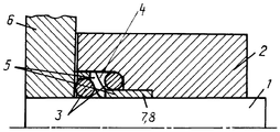
Изобретение поясняется чертежом, на котором изображен общий вид узла уплотнения в продольном разрезе.The invention is illustrated in the drawing, which shows a General view of the seal assembly in longitudinal section.
Узел уплотнения содержит вращающийся вал 1, проходящий через охватывающую деталь 2, и последовательно установленные эластичные кольца 3, размещенные в кольцевой расточке 4 между валом 1 и охватывающей деталью 2. Узел уплотнения снабжен цанговым пружинным элементом 5, установленным между уплотнительными кольцами 3 и имеющим в продольном сечении z-образную форму. Цанговый элемент 5 может быть жестко соединен с уплотнительными кольцами 3, например, путем вулканизации или любым другим известным способом. Пружинный элемент 5 соединен с охватывающей деталью 2 с возможностью совместного вращения. Это может быть обеспечено, например, их шлицевым соединением, для чего цанговый элемент 5 выполнен с выступами 7, а охватывающая часть 2 - с ответными пазами 8 на внутренней поверхности.The seal assembly comprises a rotating
Использование в узле уплотнения пружинного элемента 5, установленного между кольцами 3, обеспечивает герметизацию вала 1 при любом смещении его оси относительно оси охватывающей детали 2 и гарантированно будет перекрывать зазор, образующийся между ними в случае биения вала 1. При смещении вала 1 в вертикальной плоскости работают диагонально расположенные части колец 3, причем при смещении вала 1 вверх герметизацию вала обеспечивают верхняя половина кольца 3, расположенного в зоне контакта корпусного элемента 6 с охватывающей деталью 2, и нижняя половина второго кольца 3. При смещении вала 1 вниз уплотнение обеспечивают нижняя половина кольца 3, расположенного у основания кольцевой расточки 4, и верхняя половина второго кольца 3. Таким образом, в предложенном узле благодаря обеспечению совместной работы обоих колец 3, поджимаемых цанговым элементом 5, как при смещении оси вала 1 вверх, так и вниз, обеспечивается надежная герметизация вала 1 и предотвращается вытекание масла и попадание различных частиц из внешней среды в случае использования узла, например, в шахтных условиях.The use of a
Монтаж узла осуществляется следующим образом. Сначала на валу 1 в зоне контакта корпусного элемента 6 с охватывающей деталью 2 устанавливают первое уплотнительное кольцо 3, а затем - цанговый элемент 5. После этого у основания кольцевой расточки 4 устанавливают второе кольцо 3, совмещают выступы 7 цангового элемента 5 с ответными пазами 8 на внутренней поверхности охватывающей детали 2 и производят окончательную сборку узла уплотнения.The assembly of the node is as follows. First, on the
Такое выполнение узла уплотнения позволяет повысить надежность герметизации и тем самым повысить работоспособность всего узла.This embodiment of the seal assembly can improve the reliability of sealing and thereby increase the efficiency of the entire assembly.
Claims (2)
Priority Applications (1)
| Application Number | Priority Date | Filing Date | Title |
|---|---|---|---|
| RU2011148498/06A RU2471103C1 (en) | 2011-11-30 | 2011-11-30 | Sealing assembly of rotary shaft |
Applications Claiming Priority (1)
| Application Number | Priority Date | Filing Date | Title |
|---|---|---|---|
| RU2011148498/06A RU2471103C1 (en) | 2011-11-30 | 2011-11-30 | Sealing assembly of rotary shaft |
Publications (1)
| Publication Number | Publication Date |
|---|---|
| RU2471103C1 true RU2471103C1 (en) | 2012-12-27 |
Family
ID=49257516
Family Applications (1)
| Application Number | Title | Priority Date | Filing Date |
|---|---|---|---|
| RU2011148498/06A RU2471103C1 (en) | 2011-11-30 | 2011-11-30 | Sealing assembly of rotary shaft |
Country Status (1)
| Country | Link |
|---|---|
| RU (1) | RU2471103C1 (en) |
Cited By (1)
| Publication number | Priority date | Publication date | Assignee | Title |
|---|---|---|---|---|
| RU2708930C2 (en) * | 2015-03-30 | 2019-12-12 | Кейтерпиллар Инк. | Joint assembly seal |
Citations (5)
| Publication number | Priority date | Publication date | Assignee | Title |
|---|---|---|---|---|
| SU419673A1 (en) * | 1971-02-26 | 1974-03-15 | А. А. Штельмах, В. В. Грикевич , А. Рабинович | SEAL OF ROTATING SHAFT |
| SU1506202A1 (en) * | 1987-07-29 | 1989-09-07 | Институт Физико-Технических Проблем Севера Якутского Филиала Со Ан Ссср | Sealing device |
| SU1724980A1 (en) * | 1990-03-26 | 1992-04-07 | Кировоградский Завод Гидравлических Силовых Машин Им.Хху Съезда Кпсс "Гидросила" | Drive shaft seal of positive-displacement hydraulic machine |
| DE19924534A1 (en) * | 1998-05-29 | 1999-12-23 | Tokico Ltd | Piston rod seal device for cylinder group |
| DE10117662C1 (en) * | 2001-04-09 | 2003-01-16 | Freudenberg Carl Kg | Rod or piston primary seal |
-
2011
- 2011-11-30 RU RU2011148498/06A patent/RU2471103C1/en active
Patent Citations (5)
| Publication number | Priority date | Publication date | Assignee | Title |
|---|---|---|---|---|
| SU419673A1 (en) * | 1971-02-26 | 1974-03-15 | А. А. Штельмах, В. В. Грикевич , А. Рабинович | SEAL OF ROTATING SHAFT |
| SU1506202A1 (en) * | 1987-07-29 | 1989-09-07 | Институт Физико-Технических Проблем Севера Якутского Филиала Со Ан Ссср | Sealing device |
| SU1724980A1 (en) * | 1990-03-26 | 1992-04-07 | Кировоградский Завод Гидравлических Силовых Машин Им.Хху Съезда Кпсс "Гидросила" | Drive shaft seal of positive-displacement hydraulic machine |
| DE19924534A1 (en) * | 1998-05-29 | 1999-12-23 | Tokico Ltd | Piston rod seal device for cylinder group |
| DE10117662C1 (en) * | 2001-04-09 | 2003-01-16 | Freudenberg Carl Kg | Rod or piston primary seal |
Non-Patent Citations (1)
| Title |
|---|
| ОРЛОВ П.И. Основы конструирования. - М.: Машиностроение, 1988, т.1, с.367-368. * |
Cited By (1)
| Publication number | Priority date | Publication date | Assignee | Title |
|---|---|---|---|---|
| RU2708930C2 (en) * | 2015-03-30 | 2019-12-12 | Кейтерпиллар Инк. | Joint assembly seal |
Similar Documents
| Publication | Publication Date | Title |
|---|---|---|
| WO2008126866A1 (en) | Sealing device | |
| US20180187784A1 (en) | Sliding component | |
| US20090134583A1 (en) | Dual seal assembly | |
| US1544609A (en) | Shaft packing for turbines and the like | |
| GB2517573A (en) | Dynamically non contacting seal | |
| RU2471103C1 (en) | Sealing assembly of rotary shaft | |
| CN206988300U (en) | Sealing structure and bearing | |
| US20140319773A1 (en) | Rotary seal device | |
| GB2202285A (en) | Hydraulic sealing arrangement for sealing an annular gap | |
| US20160061265A1 (en) | Seal Arrangement for non-contact sealing of anti-friction bearings | |
| CN204985720U (en) | A sealing device for driven shaft | |
| RU2372467C1 (en) | Device for drilling of slant boreholes | |
| JPWO2015046343A1 (en) | Sliding parts | |
| US836408A (en) | Rotary-shaft packing. | |
| JP2013210071A (en) | Seal structure of endless track drive unit | |
| CN205277902U (en) | Centrifugal blower rotary main shaft's oil -sealing arrangement | |
| CN103470772B (en) | High speed and high pressure mechanical seal device | |
| CN104712766A (en) | Labyrinth type bearing closing device | |
| CN105134957A (en) | Shaft seal with labyrinth seal structure | |
| GB2582351A (en) | Seal | |
| CN105927739B (en) | A kind of fuel oil Sealing used for pump | |
| CN109611558B (en) | A differential oil seal | |
| RU47066U1 (en) | FACE SEAL | |
| CN103697169A (en) | Variable section self-tensioning rotary shaft seal ring | |
| CN203585282U (en) | Sealing device for sealing end cover on shaft |