RU2467343C2 - Method and device to detect location of communication device - Google Patents
Method and device to detect location of communication device Download PDFInfo
- Publication number
- RU2467343C2 RU2467343C2 RU2009127510/07A RU2009127510A RU2467343C2 RU 2467343 C2 RU2467343 C2 RU 2467343C2 RU 2009127510/07 A RU2009127510/07 A RU 2009127510/07A RU 2009127510 A RU2009127510 A RU 2009127510A RU 2467343 C2 RU2467343 C2 RU 2467343C2
- Authority
- RU
- Russia
- Prior art keywords
- location
- communication device
- hypothetical
- receiver
- pulse
- Prior art date
Links
Images


Classifications
-
- G—PHYSICS
- G01—MEASURING; TESTING
- G01S—RADIO DIRECTION-FINDING; RADIO NAVIGATION; DETERMINING DISTANCE OR VELOCITY BY USE OF RADIO WAVES; LOCATING OR PRESENCE-DETECTING BY USE OF THE REFLECTION OR RERADIATION OF RADIO WAVES; ANALOGOUS ARRANGEMENTS USING OTHER WAVES
- G01S5/00—Position-fixing by co-ordinating two or more direction or position line determinations; Position-fixing by co-ordinating two or more distance determinations
- G01S5/02—Position-fixing by co-ordinating two or more direction or position line determinations; Position-fixing by co-ordinating two or more distance determinations using radio waves
- G01S5/0273—Position-fixing by co-ordinating two or more direction or position line determinations; Position-fixing by co-ordinating two or more distance determinations using radio waves using multipath or indirect path propagation signals in position determination
-
- G—PHYSICS
- G01—MEASURING; TESTING
- G01S—RADIO DIRECTION-FINDING; RADIO NAVIGATION; DETERMINING DISTANCE OR VELOCITY BY USE OF RADIO WAVES; LOCATING OR PRESENCE-DETECTING BY USE OF THE REFLECTION OR RERADIATION OF RADIO WAVES; ANALOGOUS ARRANGEMENTS USING OTHER WAVES
- G01S5/00—Position-fixing by co-ordinating two or more direction or position line determinations; Position-fixing by co-ordinating two or more distance determinations
- G01S5/02—Position-fixing by co-ordinating two or more direction or position line determinations; Position-fixing by co-ordinating two or more distance determinations using radio waves
- G01S5/0205—Details
- G01S5/0244—Accuracy or reliability of position solution or of measurements contributing thereto
Abstract
Description
Уровень техникиState of the art
Настоящее изобретение относится к устройствам связи или подобным устройствам и, более конкретно, к способу и устройству для определения местоположения устройства связи или подобного устройства, выполненного с возможностью передачи или приема радиочастотного или электромагнитного сигнала.The present invention relates to communication devices or similar devices, and more particularly, to a method and apparatus for determining the location of a communication device or similar device configured to transmit or receive an RF or electromagnetic signal.
Существуют различные обстоятельства, при которых важно определить местоположение устройства связи или устройства связи, работающего в режиме передачи (передатчик) или режиме приема (приемник). Например, при применении в военных, правоохранительных или иных целях возможность определения географического местоположения радиопередатчика может быть очень полезна, в частности возможность определения местоположения, когда между передатчиком и приемником отсутствует трасса передачи в пределах прямой видимости или имеется трасса передачи не по прямой видимости (NLOS). Трассы NLOS могут быть достаточно сильными, чтобы не срабатывали фазово-когерентные методы или на антеннах имелось недостаточно места для направленных антенн. Такие сценарии могут иметь место при проведении операций в условиях непосредственной близости или когда передатчик и приемник могут находиться в одном здании.There are various circumstances in which it is important to determine the location of a communication device or a communication device operating in a transmission mode (transmitter) or a reception mode (receiver). For example, when used for military, law enforcement or other purposes, the ability to determine the geographic location of a radio transmitter can be very useful, in particular the ability to determine a location when there is no transmission path between the transmitter and the receiver within line of sight or there is a transmission path not in direct line of sight (NLOS) . NLOS paths can be strong enough so that phase-coherent methods do not work or there is not enough space on the antennas for directional antennas. Such scenarios may occur during operations in close proximity or when the transmitter and receiver can be in the same building.
Определение местоположения передатчика может быть полезным в радионавигации. Одним методом определения географического местоположения передатчика является трилатерация. Трилатерация требует минимум трех измерений дальности для определения местоположения приемника. Существующие решения, которые для трилатерации требуют трасс по прямой видимости (LOS), неприменимы, когда доступно менее трех передатчиков или когда вследствие затухания на трассе доступно менее трех регистрируемых сигналов LOS. Имеющиеся решения в случаях, когда недоступны три передатчика или сигнала LOS, могут включать в себя увеличение числа передатчиков для повышения вероятности того, что по меньшей мере три из них могут быть доступны, изменение радиопараметров линии связи, таких как частота, разнесение антенн, поляризационное разнесение и другие параметры, применение других средств навигации, таких как инерциальные устройства или подобные устройства, временную замену трилатерационной навигации до тех пор, пока не станет доступно большее число передатчиков или приемлемых трасс передачи.Locating the transmitter can be useful in radio navigation. One method for determining the geographic location of a transmitter is trilateration. Trilateration requires a minimum of three range measurements to determine the location of the receiver. Existing solutions that require line of sight (LOS) paths for trilateration are not applicable when fewer than three transmitters are available or when less than three registered LOS signals are available due to path attenuation. Available solutions in cases where three transmitters or LOS signals are unavailable may include increasing the number of transmitters to increase the likelihood that at least three of them may be available, changing radio parameters of the communication line, such as frequency, antenna diversity, polarization diversity and other parameters, the use of other navigation aids, such as inertial devices or similar devices, the temporary replacement of trilateration navigation until more transmitters are available Whether acceptable transmission paths.
Увеличение числа доступных передатчиков увеличивает эксплуатационные расходы и может снизить живучесть системы при проведении таких операций, как военные и другие операции. Изменение радиопараметров линии связи повышает сложность передатчиков и приемников и требует обмена сигналами между передатчиками и приемниками для изменения радиопараметров. Для интерциальных устройств свойственно снижение точности с течением времени.Increasing the number of available transmitters increases operating costs and can reduce system survivability in operations such as military and other operations. Changing the radio parameters of the communication line increases the complexity of the transmitters and receivers and requires the exchange of signals between transmitters and receivers to change the radio parameters. For inter-devices, accuracy decreases over time.
Сущность изобретенияSUMMARY OF THE INVENTION
В соответствии с вариантом выполнения настоящего изобретения способ определения местоположения устройства связи может включать в себя измерение времени прибытия для каждого импульса, принятого в приемнике. Способ может также включать в себя генерацию набора возможных гипотетических соответствий между каждым принятым импульсом и трассой передачи между передатчиком и приемником, причем устройство связи, местоположение которого определяется, является одним устройством из группы, состоящей из передатчика и приемника. Способ может далее включать в себя оценку местоположения устройства связи с использованием набора гипотетических соответствий.According to an embodiment of the present invention, a method for determining the location of a communication device may include measuring the arrival time for each pulse received at the receiver. The method may also include generating a set of possible hypothetical correspondences between each received pulse and the transmission path between the transmitter and the receiver, the communication device, the location of which is determined, is one device from the group consisting of a transmitter and a receiver. The method may further include estimating the location of the communication device using a set of hypothetical matches.
В соответствии с другим вариантом выполнения настоящего изобретения способ определения местоположения устройства связи может включать измерение времени прибытия для каждого импульса, принятого в приемнике. Способ может также включать в себя генерацию набора возможных гипотетических соответствий посредством сопоставления каждого импульса, принятого приемником, с возможной трассой передачи принятого импульса между передатчиком и приемником, причем устройство связи, местоположение которого определяется, является одним устройством из группы, состоящей из передатчика и приемника. Способ может дополнительно включать в себя определение геометрического места возможных местоположений устройства связи при помощи каждого набора гипотетических соответствий для каждого импульса. Способ может далее включать в себя определение предполагаемого местоположения устройства связи как пересечение геометрических мест возможных местоположений устройства связи для каждого набора гипотетических соответствий для каждого импульса.According to another embodiment of the present invention, a method for determining the location of a communication device may include measuring the arrival time for each pulse received at the receiver. The method may also include generating a set of possible hypothetical matches by matching each pulse received by the receiver with a possible transmission path of the received pulse between the transmitter and the receiver, the communication device whose location being determined is one device from the group consisting of the transmitter and receiver. The method may further include determining the geometric location of the possible locations of the communication device using each set of hypothetical correspondences for each pulse. The method may further include determining the intended location of the communication device as the intersection of the geometric locations of the possible locations of the communication device for each set of hypothetical matches for each pulse.
В соответствии с еще одним вариантом выполнения настоящего изобретения устройство для определения местоположения устройства связи может включать в себя процессор. Устройство может также включать в себя модуль определения местоположения, включающий в себя элемент оценки гипотетической трассы передачи, действующий в процессоре, для оценки соответствия между каждым принятым импульсом и возможной трассой передачи импульса для определения местоположения устройства связи.In accordance with yet another embodiment of the present invention, a device for determining the location of a communication device may include a processor. The device may also include a location module, including a hypothetical transmission path evaluation element operating in the processor, for evaluating the correspondence between each received pulse and a possible pulse transmission path for determining the location of the communication device.
В соответствии с еще одним вариантом выполнения настоящего изобретения компьютерный программный продукт для определения местоположения устройства связи может включать в себя используемую компьютером среду, содержащую реализованный в ней используемый компьютером программный код. Используемая компьютером среда может включать в себя используемый компьютером программный код, выполненный с возможностью измерения времени прибытия для каждого импульса, принятого в приемнике. Используемая компьютером среда может также включать в себя используемый компьютером программный код, выполненный с возможностью генерации набора возможных гипотетических соответствий между каждым принятым импульсом и возможной трассой передачи импульса между передатчиком и приемником, причем устройство связи, местоположение которого определяется, является одним устройством из группы, состоящей из передатчика и приемника. Используемая компьютером среда может также включать в себя используемый компьютером программный код, выполненный с возможностью оценки местоположения устройства связи с использованием набора гипотетических соответствий.According to yet another embodiment of the present invention, a computer program product for determining the location of a communication device may include a computer environment containing computer program code implemented therein. The medium used by the computer may include computer program code configured to measure the arrival time for each pulse received at the receiver. The medium used by the computer may also include the program code used by the computer, configured to generate a set of possible hypothetical correspondences between each received pulse and a possible pulse transmission path between the transmitter and the receiver, the communication device, the location of which is determined, is one device from the group consisting of from the transmitter and receiver. The computer-used medium may also include computer-programmed code configured to estimate the location of the communication device using a set of hypothetical matches.
В соответствии с еще одним вариантом выполнения настоящего изобретения средство передвижения может включать в себя устройство для определения местоположения средства передвижения. Устройство может включать в себя процессор и модуль определения местоположения, включающий в себя элемент оценки гипотетического соответствия, действующий в процессоре, для оценки соответствия между каждым принятым импульсом и возможной трассой передачи импульса для определения местоположения средства передвижения.According to another embodiment of the present invention, the vehicle may include a device for determining the location of the vehicle. The device may include a processor and a location module, including a hypothetical match assessment element operating in the processor, for evaluating the correspondence between each received pulse and a possible pulse transmission path for determining the location of the vehicle.
Другие аспекты и особенности настоящего изобретения, определяемого исключительно формулой, станут ясны специалисту в данной области техники после ознакомления с нижеследующим неограниченным подробным описанием изобретения в сочетании с прилагаемыми чертежами.Other aspects and features of the present invention, defined solely by the claims, will become apparent to a person skilled in the art after reading the following unlimited detailed description of the invention in combination with the accompanying drawings.
Краткое описание нескольких видов на чертежахA brief description of several views in the drawings
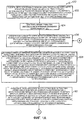
Фиг.1А и 1В (совместно фиг.1) - блок-схема последовательности операций для примерного способа определения местоположения устройства связи в соответствии с вариантом выполнения настоящего изобретения.1A and 1B (together FIG. 1) is a flowchart for an example method for determining a location of a communication device in accordance with an embodiment of the present invention.
Фиг.2 - иллюстрация примерных трасс передачи для определения местоположения устройства связи в соответствии с вариантом выполнения настоящего изобретения.FIG. 2 is an illustration of exemplary transmission paths for locating a communication device in accordance with an embodiment of the present invention.
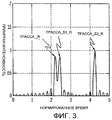
Фиг.3 - иллюстрация принятых импульсов сигналов, соответствующих каждой из примерных трасс передачи, приведенных на фиг.2.Figure 3 - illustration of the received pulses of the signals corresponding to each of the exemplary transmission paths shown in figure 2.
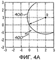
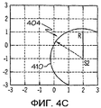
Фиг.4A-4C - иллюстрации примеров геометрических мест возможных местоположений устройства связи, использующих гипотетические трассы передачи, в соответствии с вариантом выполнения настоящего изобретения.4A-4C are illustrations of examples of geometric locations of possible locations of a communication device using hypothetical transmission paths in accordance with an embodiment of the present invention.
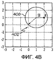
Фиг.4D - иллюстрация примера оценки местоположения устройства связи на основе пересечения геометрических мест возможных местоположений в соответствии с вариантом выполнения настоящего изобретения.FIG. 4D is an illustration of an example location estimation of a communication device based on intersection of geometric locations of possible locations in accordance with an embodiment of the present invention.
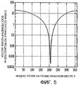
Фиг.5 - иллюстрация примера определения остаточной погрешности для предполагаемого местоположения устройства связи в соответствии с вариантом выполнения настоящего изобретения.5 is an illustration of an example of determining a residual error for an estimated location of a communication device in accordance with an embodiment of the present invention.
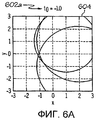
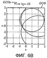
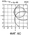
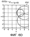
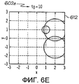
Фиг.6А-6K иллюстрируют пример определения предполагаемого местоположения устройства связи, когда время передачи импульса неизвестно, в соответствии с вариантом выполнения настоящего изобретения.6A-6K illustrate an example of determining an estimated location of a communication device when a pulse transmission time is not known, in accordance with an embodiment of the present invention.
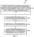
Фиг.7 - блок-схема последовательности операций для примера способа генерации возможных гипотетических трасс передачи для каждого принятого импульса и времени передачи импульса в соответствии с вариантом выполнения настоящего изобретения.7 is a flowchart for an example of a method for generating possible hypothetical transmission paths for each received pulse and pulse transmission time in accordance with an embodiment of the present invention.
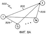
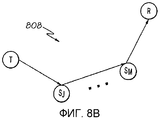
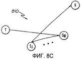
Фиг.8A-8C - примеры гипотетических трасс передачи от передатчика к приемнику в соответствии с вариантом выполнения настоящего изобретения.8A-8C are examples of hypothetical transmission paths from a transmitter to a receiver in accordance with an embodiment of the present invention.
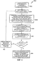
Фиг.9 - блок-схема последовательности операций для примера способа выбора наилучшей или оптимальной оценки местоположения для устройства связи посредством вычисления остаточной погрешности для каждой оценки местоположения в соответствии с вариантом выполнения настоящего изобретения.FIG. 9 is a flowchart for an example of a method for selecting the best or optimal location estimate for a communication device by calculating a residual error for each location estimate in accordance with an embodiment of the present invention.
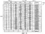
Фиг.10 - таблица, иллюстрирующая пример наборов гипотетических соответствий между каждым принятым импульсом и возможной трассой передачи, по которой, возможно, была осуществлена передача импульса, в соответствии с вариантом выполнения настоящего изобретения.10 is a table illustrating an example of sets of hypothetical correspondences between each received pulse and a possible transmission path along which a pulse transmission may have been made, in accordance with an embodiment of the present invention.
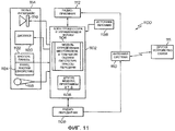
Фиг.11 - блок-схема примера устройства для определения местоположения устройства связи в соответствии с вариантом выполнения настоящего изобретения.11 is a block diagram of an example of a device for determining the location of a communication device in accordance with an embodiment of the present invention.
Подробное описание изобретенияDETAILED DESCRIPTION OF THE INVENTION
Нижеследующее подробное описание вариантов выполнения содержит ссылки на прилагаемые чертежи, которые иллюстрируют частные варианты выполнения изобретения. Другие варианты выполнения, содержащие иные конструктивные особенности и действия, не выходят за пределы объема настоящего изобретения.The following detailed description of embodiments contains references to the accompanying drawings, which illustrate particular embodiments of the invention. Other embodiments containing other design features and actions are not beyond the scope of the present invention.
Как должно быть понятно специалисту в данной области техники, раскрытое техническое решение может быть реализовано в виде способа, системы или компьютерного программного продукта. Соответственно, раскрытое техническое решение может принимать вид полностью аппаратного варианта выполнения, полностью программного варианта выполнения (включая встроенное программное обеспечение, резидентное программное обеспечение, микрокод и т.д.) или варианта выполнения, сочетающего в себя программные и аппаратные аспекты, которые все могут в целом называться в настоящей заявке "схема", "модуль" или "система". Кроме того, настоящее изобретение может принимать вид компьютерного программного продукта на используемом компьютером носителе данных, имеющем используемый компьютером программный код, реализованный на носителе.As should be clear to a person skilled in the art, the disclosed technical solution can be implemented in the form of a method, system or computer program product. Accordingly, the disclosed technical solution may take the form of a fully hardware embodiment, a fully software embodiment (including firmware, resident software, microcode, etc.) or an embodiment combining software and hardware aspects that all can Generally referred to in this application as "circuit", "module" or "system". In addition, the present invention may take the form of a computer program product on a computer storage medium having a computer program code implemented on a medium.
Можно использовать любой подходящий используемый компьютером или машиночитаемый носитель. В частности, используемый компьютером или машиночитаемый носитель может быть электронной, магнитной, оптической, электромагнитной, инфракрасной или полупроводниковой системой, устройством или средой распространения. Частные примеры (неисчерпывающий список) машиночитаемых носителей включают в себя следующее: электрическое соединение, имеющее один или более проводов, переносную компьютерную дискету, жесткий диск, оперативную память (RAM), постоянную память (ROM), стираемую программируемую постоянную память (EPROM или флэш-память), оптическое волокно, постоянную память на переносном компакт-диске (CD-ROM), оптическое запоминающее устройство, среду передачи, например среды, поддерживающие Интернет и интрасеть, или магнитное запоминающее устройство. Заметим, что используемым компьютером или машиночитаемым носителем может быть даже бумага или иной подходящий носитель, на котором напечатана программа, поскольку эта программа может быть считана электронным образом, например, при помощи оптического сканирования бумаги или иного носителя, затем, в случае необходимости, скомпилирована, интерпретирована или иным образом обработана подходящим образом, после чего сохранена в памяти компьютера. В контексте настоящего документа используемый компьютером или машиночитаемый носитель может быть любым носителем, который может содержать, хранить, передавать, распространять или транспортировать программу для использования системой или устройством для выполнения команд или в связи с такой системой или устройством.Any suitable computer or machine-readable medium may be used. In particular, the computer or machine-readable medium used may be an electronic, magnetic, optical, electromagnetic, infrared, or semiconductor system, device, or propagation medium. Particular examples (non-exhaustive list) of machine-readable media include the following: an electrical connection having one or more wires, a portable computer diskette, hard disk, random access memory (RAM), read-only memory (ROM), erasable programmable read-only memory (EPROM or flash memory), optical fiber, read-only memory on portable compact disc (CD-ROM), optical storage device, transmission medium, such as media that support the Internet and intranet, or magnetic storage device. Note that the computer or machine-readable medium used may even be paper or other suitable medium on which the program is printed, since this program can be read electronically, for example, by optical scanning of paper or other medium, then, if necessary, compiled, interpreted or otherwise processed appropriately, and then stored in computer memory. In the context of this document, the computer or machine-readable medium used may be any medium that may contain, store, transmit, distribute or transport a program for use by a system or device for executing instructions or in connection with such a system or device.
Компьютерный программный код для выполнения операций раскрытого технического решения может быть написан на объектно-ориентированном языке программирования, таком как Java, Smalltalk, C++ или подобном. Однако компьютерный программный код для выполнения этих операций может быть также написан на обычных процедурных языках программирования, таком как язык программирования "С" или подобные языки программирования. Программный код может выполняться целиком на компьютере пользователя, частично на компьютере пользователя, в качестве автономного программного пакета, частично на компьютере пользователя и частично на удаленном компьютере или полностью на удаленном компьютере или сервере. В последнем сценарии удаленный компьютер может быть соединен с компьютером пользователя посредством локальной сети (LAN) или глобальной сети (WAN) или может быть выполнено соединение с внешним компьютером (например, через Интернет при помощи поставщика услуг в сети Интернет).The computer program code for performing the operations of the disclosed technical solution may be written in an object-oriented programming language such as Java, Smalltalk, C ++ or the like. However, computer program code for performing these operations may also be written in conventional procedural programming languages, such as programming language "C" or similar programming languages. The program code may be executed entirely on the user's computer, partially on the user's computer, as a stand-alone software package, partially on the user's computer and partially on the remote computer or completely on the remote computer or server. In the latter scenario, the remote computer can be connected to the user's computer via a local area network (LAN) or wide area network (WAN), or it can be connected to an external computer (for example, via the Internet using an Internet service provider).
Наше техническое решение описано ниже со ссылкой на блок-схемы последовательности операций и (или) блок-схемы способов, устройств (систем) и компьютерных программных продуктов согласно вариантам выполнения изобретения. Должно быть понятно, что каждый блок на блок-схемах последовательности операций и (или) на блок-схемах и сочетания блоков на блок-схемах последовательности операций и (или) блок-схемах могут быть реализованы посредством команд компьютерной программы. Эти команды компьютерной программы могут поступать на процессор компьютера общего назначения, компьютера специального назначения или другое программируемое устройство обработки данных для создания машины, так что команды, которые выполняются посредством процессора компьютера или другого программируемого устройства обработки данных, создают средство для реализации функций/действий, указанных в блоке или блоках блок-схемы последовательности операций и (или) блок-схемы.Our technical solution is described below with reference to flowcharts and / or flowcharts of methods, devices (systems) and computer software products according to embodiments of the invention. It should be understood that each block in flowcharts and / or flowcharts and combinations of blocks in flowcharts and / or flowcharts can be implemented using computer program instructions. These computer program instructions may be sent to a general purpose computer processor, special purpose computer, or other programmable data processing device to create a machine, so that the commands that are executed by a computer processor or other programmable data processing device provide a means for implementing the functions / actions indicated in a block or blocks of a flowchart and / or a flowchart.
Эти команды компьютерной программы могут также храниться в машиночитаемой памяти, которая может управлять компьютером или другим программируемым устройством обработки данных, чтобы они функционировали определенным образом, так чтобы команды, хранящиеся в машиночитаемой памяти, создавали изделие, включающее в себя командное средство, которое реализует функцию/действия, указанные в блоке или блоках блок-схемы последовательности операций и (или) блок-схемы.These computer program instructions may also be stored in a machine-readable memory that can control a computer or other programmable data processing device so that they function in a certain way, so that instructions stored in a computer-readable memory create an article including command means that implements the / actions indicated in the block or blocks of the flowchart of the sequence of operations and (or) the flowchart.
Команды компьютерной программы могут также быть загружены в компьютер или другое программируемое устройство обработки данных, чтобы вызвать выполнение последовательности функциональных этапов на компьютере или другом программируемом устройстве для создания реализуемого на компьютере процесса, так чтобы команды, которые выполняются на компьютере или другом программируемом устройстве, обеспечивали этапы для реализации функций/действий, указанных в блоке или блоках блок-схемы последовательности операций и (или) блок-схемы.Computer program instructions may also be downloaded to a computer or other programmable data processing device to cause a series of functional steps to be performed on a computer or other programmable device to create a process implemented on a computer so that instructions that are executed on a computer or other programmable device provide steps to implement the functions / actions specified in the block or blocks of the flowchart of the sequence of operations and (or) the flowchart.
На фиг.1А и 1В (совместно фиг.1) приведена блок-схема примерного способа 100 для определения местоположения устройства связи в соответствии с вариантом выполнения настоящего изобретения. В рамках настоящей заявки устройство связи может быть приемником или передатчиком, и эти термины могут применяться в настоящей заявке взаимозаменяемым образом. Приемник может быть устройством связи, работающим в качестве приемника или в режиме приема. Передатчик может быть устройством связи, работающим в качестве передатчика или в режиме передачи.On figa and 1B (together figure 1) is a block diagram of an
В блоке 102 можно оценить местоположение приемника. Местоположение может быть географическим местоположением, местоположением на некоторой сетке или в некоторой системе координат или любым иным способом идентификации местоположения устройства связи относительно другого устройства связи или других ориентиров или объектов. Местоположение приемника можно оценить при помощи глобальной системы позиционирования (GPS), топографической съемки, триангуляции LOS, триангуляции NLOS, триангуляция с использованием радиочастотного или оптического передатчика или других методов определения местоположения.At
Кроме того, в блоке 102 может передаваться импульс или множество импульсов от передатчика. В зависимости от того, является ли устройство связи, местоположение которого определяется, передатчиком или приемником, местоположение другого устройства, местоположение которого не определяется или не оценивается, может быть известно или может использоваться опорный приемник с известным местоположением и длиной трассы от устройства, местоположение которого не определяется, для определения местоположения неизвестного устройства.In addition, in
В блоке 104 можно измерить или записать в приемнике время прибытия импульса или импульсов. Время прибытия импульсов можно определить посредством взаимной корреляции или иных методов.At
В блоке 106 может быть сгенерирован набор гипотетических соответствий посредством сопоставления каждого принятого импульса с возможной трассой передачи между передатчиком и приемником. Каждое гипотетическое соответствие может представлять собой гипотезу о том, что принятый импульс был передан через сопоставленную трассу передачи. Если время передачи импульса неизвестно, может быть сгенерирован другой набор гипотез для каждого гипотетического времени и трассы передачи. Пример способа для генерации гипотетических соответствий более подробно описан ниже со ссылкой на фиг.7. Если говорить кратко, можно определить все возможные трассы передачи от передатчика к приемнику, включая отклонения, отражения или рассеяние импульса сигнала от любых рассеивающих центров, которые могут оказаться на трассе передачи. Все сочетания трасс передачи могут быть сгруппированы в наборы элементов (трасс) на основе числа принятых импульсов. Затем может быть установлено однозначное соответствие между каждым набором элементов или трасс передачи с принятым импульсом. Принятый импульс может быть гипотетически сопоставлен с множеством возможных трасс передачи. Затем может быть определено наилучшее или оптимальное соответствие между каждым принятым импульсом и возможной трассой передачи.At
Трасса передачи может быть определена как упорядоченный набор, состоящий из передатчика, нулевого или большего числа рассеивающих центров и приемника. Трассы передачи по прямой видимости (LOS) не имеют рассеивающих центров на трассе. Трассы передачи не по прямой видимости (NLOS) имеют один или несколько рассеивающих центров на трассе. Передатчики, приемники и рассеивающие центры могут быть определены как узлы на трассе передачи. Способ 100 или алгоритм предполагает, что географическое местоположение каждого узла известно до начала работы, за исключением одного устройства связи (передатчик или приемник в зависимости от ситуации), местоположение которого нужно определить. Способ 100 или алгоритм также предполагает, что любая задержка на распространение, присущая каждому узлу, и любая задержка на звеньях между каждым узлом известны, за исключением последнего звена, которое заканчивается на устройстве связи, местоположение которого нужно определить. Рассеивающий центр может быть любой структурой, которая может находиться на трассе передачи между передатчиком и приемником.A transmission path can be defined as an ordered set consisting of a transmitter, zero or more scattering centers, and a receiver. Line of sight (LOS) transmission paths do not have scattering centers on the path. Off-line-of-sight (NLOS) transmission paths have one or more scattering centers on the path. Transmitters, receivers and scattering centers can be defined as nodes on the transmission path.
Если обратиться также к фиг.2 и 3, то фиг.2 служит иллюстрацией примеров трасс 200 передачи для определения местоположения устройства связи в соответствии с вариантом выполнения настоящего изобретения. В примере на фиг.2 может быть неизвестно местоположение передатчика (Т). Примерные трассы 200 передачи могут включать в себя прямую трассу передачи или трассу 202 передачи LOS от приемника (R) к передатчику (Т). Трасса передачи T-S1-R 204 идет от передатчика, отражается или рассеивается на рассеивающем центре S1 и затем приходит в приемник. Трасса передачи T-S2-R 206 идет от передатчика, отражается или рассеивается от рассеивающего центра S2 и затем приходит в приемник. Возможны также трассы передачи с двукратными отражениями, которые на фиг.2 не показаны, такие как T-S1-S2-R или T-S2-S1-R. Как описано выше, эти трассы передачи с одним или несколькими рассеивающими центрами (S1 и S2) можно называть трассами передачи NLOS.Referring also to FIGS. 2 and 3, FIG. 2 illustrates examples of
На фиг.3 показаны импульсы сигнала, принятые приемником (R), которые могут гипотетически соответствовать каждой из примерных трасс 200 передачи на фиг.2. Фиг.3 также иллюстрирует измерение или определение времени прибытия для каждого импульса, как в блоке 104. В блоке 108 для каждого принятого импульса может быть определено геометрическое место возможных местоположений устройства связи (передатчика или приемника, в зависимости от того, местоположение какого устройства определяется) с использованием гипотетического соответствия или соответствий, включающих в себя возможные трассы передачи, по которым может следовать каждый импульс. Если устройство связи, местоположение которого нужно определить, является передатчиком, геометрические места возможных местоположений устройства связи могут включать в себя окружность с центром в приемнике для гипотетического соответствия, связанного с определенным принятым импульсом, которое включает в себя путь передачи LOS, и окружность с центром в каждом первом рассеивающем центре, считая от передатчика, для каждого гипотетического совпадения, связанного с определенным принятым импульсом, которое включает в себя трассу передачи NLOS. Если устройство связи, местоположение которого нужно определить, является приемником, геометрические места возможных местоположений устройства связи могут включать в себя окружность с центром в передатчике для каждого гипотетического соответствия, связанного с определенным принятым импульсом, которое включает в себя трассу передачи LOS, и окружность с центром в каждом последнем рассеивающем центре перед приемником для каждого гипотетического соответствия, связанного со определенным принятым импульсом, которое включает в себя трассу передачи NLOS.Figure 3 shows the signal pulses received by the receiver (R), which may hypothetically correspond to each of the
Если обратиться также к фиг.4А-4С, то фиг.4А-4С иллюстрируют примеры геометрических мест 400-404 возможных местоположений устройства связи, полученных с использованием гипотетического соответствия между каждым принятым импульсом и трассой передачи, в соответствии с вариантом выполнения настоящего изобретения. Частный пример, приведенный на фиг.4А-4С, относится к определению местоположения передатчика (Т) на фиг.2. Соответственно, возможные местоположения устройства связи или передатчика (Т) для гипотетического соответствия, включающего в себя трассу передачи T-R, дают геометрическое место 400, определенное окружностью 406 с центром в приемнике (R). Возможные местоположения передатчика (Т) для гипотетического соответствия или гипотезы, включающей в себя трассу передачи T-S1-R, дают геометрическое место 402, определяемое окружностью 408 с центром в рассеивающем центре S1. Возможные местоположения передатчика (Т) для гипотетической трассы передачи T-S2-R дают геометрическое место 404, определяемое кругом 410 с центром в рассеивающем центре S2.Referring also to FIGS. 4A-4C, FIGS. 4A-4C illustrate examples of geometric locations 400-404 of possible locations of a communication device obtained using a hypothetical match between each received pulse and transmission path, in accordance with an embodiment of the present invention. A particular example shown in figa-4C, relates to the location of the transmitter (T) in figure 2. Accordingly, the possible locations of the communication device or transmitter (T) for a hypothetical match, including the T-R transmission path, give a
Радиус каждой окружности 406, 408 и 410 может быть определен посредством следующих вычислений для каждой трассы передачи:The radius of each
a) вычисление времени распространения от первого рассеивающего центра на трассе приемнику:a) calculating the propagation time from the first scattering center on the path to the receiver:
t1 = (длина трассы / скорость распространения) + временная задержка рассеивающих центров;t1 = (path length / propagation velocity) + time delay of scattering centers;
b) вычисление полного времени распространения:b) calculation of the total propagation time:
t2 = время приема соответствующего импульса;t2 = time of reception of the corresponding pulse;
c) вычисление времени распространения на первом звене (от передатчика к первому рассеивающему центру):c) calculating the propagation time at the first link (from the transmitter to the first scattering center):
t3=t2-t1 - временные задержки в приемнике;t3 = t2-t1 - time delays in the receiver;
d) вычисление отрезка трассы первого звена:d) the calculation of the segment of the route of the first link:
R=t3 * скорость распространения;R = t3 * propagation speed;
e) поиск местоположения возможных местоположений передатчика:e) search for locations of possible transmitter locations:
геометрическое место возможных местоположений - окружность радиуса R с центром в первом рассеивающем центре на трассе передачи.the geometric place of possible locations is a circle of radius R centered at the first scattering center on the transmission path.
Аналогичная совокупность вычислений может быть выполнена при определении или оценке местоположения приемника. Может быть вычислено время распространения от известного местоположения передатчика до последнего рассеивающего центра перед приемником. Затем можно определить время распространения от последнего рассеивающего центра до приемника по разнице между полным временем распространения и временем распространения от передатчика до последнего рассеивающего центра минус любые задержки распространения в приемнике. Геометрическое место возможных местоположений приемника может в этом случае представлять собой окружность с центром в последнем рассеивающем центре с радиусом, соответствующим отрезку трассы от последнего рассеивающего центра до приемника. Длину отрезка трассы можно вычислить, умножив время распространения от последнего рассеивающего центра до приемника на скорость распространения.A similar set of calculations can be performed when determining or evaluating the location of the receiver. The propagation time from the known transmitter location to the last scattering center in front of the receiver can be calculated. You can then determine the propagation time from the last scattering center to the receiver by the difference between the total propagation time and the propagation time from the transmitter to the last scattering center minus any propagation delays in the receiver. The geometric location of the possible locations of the receiver may in this case be a circle centered at the last scattering center with a radius corresponding to the distance from the last scattering center to the receiver. The path length can be calculated by multiplying the propagation time from the last scattering center to the receiver by the propagation speed.
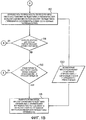
В блоке 110 предполагаемое местоположение или местоположения передатчика или приемника, в зависимости от того, местоположение какого устройства нужно определить, может быть определено как пересечение геометрических мест для каждого принятого импульса. Иными словами, если определяется местоположение передатчика, предполагаемое местоположение устройства связи может быть пересечением окружностей для каждого соответствующего принятого импульса с центром в первых рассеивающих импульсах, считая от передатчика, и окружности с центром в приемнике для принятого импульса или гипотетического соответствия, включающего в себя трассу передачи LOS. Если определяется местоположение приемника, предполагаемое местоположение или местоположения могут быть пересечением окружностей для каждого соответствующего принятого импульса с центром в последних рассеивающих центрах перед приемником и окружности с центром в передатчике для гипотетического соответствия, включающего трассу передачи LOS.At
Обратимся также к фиг.4D, на которой приведен пример оценки местоположения устройства связи на основе пересечения геометрических мест 412 возможных местоположений в соответствии с вариантом выполнения настоящего изобретения. Фиг.4D является продолжением того же примера, что приведен на фиг.2 и фиг.4А-4С. Предполагаемое местоположение устройства связи или передатчика (Т) в данном примере представляет собой пересечение 414.Referring also to FIG. 4D, an example is provided for estimating the location of a communication device based on the intersection of
В блоке 112 может быть погрешность пересечения посредством задания набора контрольных точек на одном из круговых геометрических мест. Для каждой контрольной точки эта точка может быть подставлена в каждое из остальных геометрических мест, и для каждой подстановки вычисляется остаточная погрешность. Погрешность пересечения в каждой контрольной точке может быть определена как сумма остаточных погрешностей от каждого геометрического места в блоке 110. Возможным местоположением устройства связи может быть выбрана контрольная точка с минимальной суммой остаточных погрешностей. Погрешность пересечения для этого набора геометрических мест - это погрешность пересечения, соответствующая предполагаемому местоположению устройства связи. Фиг.5 иллюстрирует пример определения остаточной погрешности для предполагаемого местоположения устройства связи в соответствии с вариантом выполнения настоящего изобретения. На фиг.5 приведен график зависимости остаточной погрешности от индекса точки на геометрическом месте. По вертикальной оси отложена сумма остаточных погрешностей на всех других геометрических местах, а по горизонтальной оси отложен индекс точки на геометрическом месте 0. Пример способа определения погрешности пересечения для каждой оценки местоположения устройства связи более подробно описан ниже со ссылкой на фиг.9.At
В блоке 114 может быть определено, требуется ли оценивать местоположение для другого гипотетического времени передачи. Как говорилось выше, если времена передачи импульсов неизвестны, могут быть выдвинуты дополнительные гипотезы для возможных времен передачи и трасс передачи. Если имеется дополнительное гипотетическое время передачи, которое подлежит применению, выполнение способа 100 может вернуться к блоку 106, и способ 100 может далее выполняться так, как описано выше. Если дополнительные гипотетические времена передачи отсутствуют, выполнение способа 100 может перейти к блоку 116.At
В блоке 116 может быть определено, требуются ли новые гипотетические соответствия между принятыми импульсами и трассами передачи. Если новые гипотетические соответствия между принятыми импульсами и трассами передачи требуются, выполнение способа 100 может вернуться к блоку 106, и выполнение способа 100 может осуществляться так, как описано выше. Если новое гипотетическое соответствие между принятым импульсом и трассой передачи не требуется в блоке 116, выполнение способа 100 может перейти к блоку 118.At
В блоке 118 может быть выбрана наилучшая или оптимальная оценка местоположения для устройства связи (передатчика или приемника) в качестве оценки возможного местоположения устройства связи с наименьшей погрешностью 120 пересечения.At
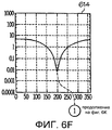
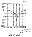
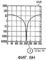
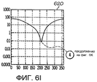
На фиг.6А-6K приведен пример определения предполагаемого местоположения устройства связи, когда время передачи импульса неизвестно, в соответствии с вариантом выполнения настоящего изобретения. Может быть определено пересечение геометрических мест 600 для каждой гипотетической трассы передачи для каждого импульса и каждого гипотетического времени 602 передачи импульса (t0=-1,0; t0=-0,5; t0=0,0 и т.д.) (как в блоке 110 на фиг.1), что на графиках 604-612 приведено как предполагаемое местоположение для устройства связи. Погрешность пересечения для каждой оценки местоположения устройства связи на графиках 604-612 может быть определена способом, аналогичным описанному в отношении блока 112 на фиг.1. График погрешностей пересечения для каждой из соответствующих оценок местоположения устройства связи, приведенных на графиках 604-612, изображен на графиках 614-622. Каждый из графиков 614-622 соответствует соответственно предполагаемым местоположениям, приведенным на графиках 604-612. Графики 614-622 представляют собой зависимости остаточной погрешности от индекса точки. По вертикальной оси отложена сумма остаточных погрешностей на всех других геометрических местах, а по горизонтальной оси отложен индекс точки на геометрическом месте 0. В качестве лучшей или оптимальной оценки местоположения устройства связи может быть выбрана оценка местоположения с самой низкой погрешностью пересечения (определенной в блоке 118 на фиг.1), которая приведена на графике 624 на фиг.6K. График 624 является графиком зависимости минимальных остаточных погрешностей (вертикальная ось) от времени передачи импульса (t0) 602 (горизонтальная ось) для каждой суммы остаточных погрешностей, приведенных на графиках 614-622. Как следует из графика 624, оптимальная или наилучшая оценка местоположения устройства связи дается пересечением окружностей или геометрических мест на графике 608 в примере, изображенном на фиг.6A-6K.6A-6K show an example of determining the estimated location of a communication device when the transmission time of the pulse is unknown, in accordance with an embodiment of the present invention. The intersection of geometric locations 600 for each hypothetical transmission path for each pulse and each hypothetical pulse transmission time 602 (t 0 = -1.0; t 0 = -0.5; t 0 = 0.0, etc., can be determined). ) (as in
На фиг.7 приведена блок-схема последовательности операций для примера способа 700 генерации возможных гипотетических трасс передачи для каждого принятого импульса и времени передачи импульса в соответствии с вариантом выполнения настоящего изобретения. Способ 700 можно применять в блоке 106 способа 100 на фиг.1. В блоке 702 возможные трассы передачи от передатчика (Т) к приемнику (R) включают в себя все сочетания для отражений и рассеяния от любых рассеивающих центров (SM). Пример определения возможных трасс 800 приведен на фиг.8А-8С. Возможные трассы 800 передачи могут включать в себя прямую трассу T-R 802, одно отражение от каждого рассеивающего центра SM, T-SJ-R 804, T-SM-R 806, двойное отражение T-SJ-SM-R 808 или T-SM-SJ-R 810. Общее число возможных трасс для М рассеивающих центров может быть представлено уравнением 1:7 is a flowchart for an example of a
![]()
![]()
где Nтрасс - число трасс, а K - максимальное число отражений на трассе.where N traces - the number of traces, and K - the maximum number of reflections on the track.
Гипотеза может включать в себя время передачи t0 и Nимпульсов пар из импульсов и трасс передачи. Трасса передачи может определяться или задаваться значением Трассаj, где j - целое число между 1 и Nтрасс. Импульс может определяться значением Импульсi, где i - целое число между 1 и Nимпульс. Соединение импульса Импульсi и трассы Трассаj в пару может обозначаться как (Импульсi, Трассаj). Это соединение может представить гипотезу, что Импульсi является результатом сигнала, проходящего по трассе Трассаj.The hypothesis may include the transmission time t 0 and N pulses of pairs of pulses and transmission paths. The transmission route can be determined or set by the value of the Track j , where j is an integer between 1 and N traces. The momentum can be determined by the value of momentum i , where i is an integer between 1 and N momentum . The connection of the impulse Impulse i and the route of the Track j in a pair can be denoted as (Impulse i , Route j ). This connection may represent the hypothesis that Impulse i is the result of a signal passing along the route j .
Только одна гипотеза может включать в себя время передачи t0 и Nимпульсов пар (импульс, трасса). Каждая пара (импульс, трасс) может иметь неповторяющийся импульс, так чтобы гипотеза включала в себя одну трассу для каждого импульса. Например, если имеется 3 принятых импульса и 10 возможных трасс, то набор пар для гипотезы мог бы быть таким: (Импульс1, Трасса10), (Импульс2, Трасса1), (Импульс3, Трасса4).Only one hypothesis can include the transmission time t 0 and N pulses of pairs (pulse, path). Each pair (impulse, traces) can have a non-repeating impulse, so that the hypothesis includes one trace for each impulse. For example, if there are 3 received impulses and 10 possible paths, then the set of pairs for the hypothesis could be: (Impulse 1 , Route 10 ), (Impulse 2 , Route 1 ), (Impulse 3 , Route 4 ).
В блоке 704 могут быть определены все перестановки Nтpaсс трасс передачи и сгруппированы в наборы элементов (трасс) на основе числа принятых импульсов (Nимпульсов). Числом перестановок Nтpacc трасс за один раз дается выражением: М=Nтpacc!/(Nтpacc-Nимпульсов)!In
Число гипотез Nh может быть получено умножением числа времен передачи Ntt на число перестановок трасс М. В блоке 706 каждый набор элементов (трасс) может быть связан или сопоставлен с уникальным импульсом для каждой перестановки. В блоке 708 может быть получено гипотетическое соответствие для каждой перестановки для каждого времени передачи или гипотетического времени передачи, если время передачи неизвестно. Этот способ может быть обобщен на случай применения более одного приемника. В этом случае способ создания трасс передачи может быть применен циклически для получения еще одного набора трасс передачи для каждого приемника.The number of hypotheses N h can be obtained by multiplying the number of transmission times N tt by the number of permutations of traces M. At
На фиг.9 приведена блок-схема последовательности операций для примера способа 900 выбора наилучшей или оптимальной оценки местоположения для устройства связи посредством вычисления остаточной погрешности для каждой оценки местоположения в соответствии с вариантом выполнения настоящего изобретения. Способ 900 может применяться для выполнения операций в модуле или блоке 112 на фиг.1. В блоке 902 может быть выбрано одно из геометрических мест возможных местоположений устройства связи (передатчика или приемника). В блоке 904 геометрические места могут быть аппроксимированы набором отдельных точек (xi,yi).FIG. 9 is a flowchart for an example of a
В блоке 906 каждая отдельная точка может быть циклически подставлена в другие геометрические места для каждого возможного местоположения устройства связи. Каждая отдельная точка может быть подставлена в математическое представление для других геометрических мест (k) для каждого возможного местоположения устройства связи.At
В блоке 908 может быть определена остаточная погрешность для каждой отдельной точки в геометрических местах (k) для каждого другого возможного местоположения устройства связи. (Погрешностьi,k=(xi-xk)2+(y1-yk)2-(rk)2). Где rk - радиус геометрических мест (k). В блоке 910 может быть определена сумма квадратов остаточных погрешностей для каждой отдельной точки (Погрешностьi=Σk|Погрешностьi,k|2).At
В блоке 911 может быть определено, были ли выбраны все геометрические места возможных положений устройства связи. Если не все, может быть выбрано геометрическое место для другого из возможных местоположений устройства связи, и выполнение способа 900 может вернуться к блоку 904. Затем способ может выполняться так, как описано выше. Если выбраны все геометрические места возможных местоположений устройства связи, выполнение способа 900 может перейти к блоку 914.At
В блоке 914 может быть выбрано возможное местоположение устройства связи в отдельной точке с минимальной суммой остаточных погрешностей. Минимальная сумма остаточных погрешностей может использоваться для выбора точки в качестве показателя погрешности при оценке местоположения.At
На фиг.10 приведена таблица 1000, иллюстрирующая пример наборов гипотетических соответствий 1002 между каждым принятым импульсом и возможной трассой передачи, по которой импульс мог быть передан, в соответствии с вариантом выполнения настоящего изобретения. Гипотетические соответствия 1002 основаны на примере, приведенном на фиг.2. Гипотетические соответствия могут быть получены способом, аналогичным описанному в отношении блока 106 на фиг.1 и способа 700 на фиг.7. Как показано на фиг.10, первый прибывший импульс или импульс с наименьшим временем прибытия в столбце 1004 может считаться трассой передачи LOS или прямой трассой от передатчика (Т1) к приемнику (R1), или трассой 202 передачи на фиг.2. Другие возможные трассы передачи, сопоставляемые с импульсами с более поздним временем прибытия, могут быть трассами передачи NLOS, которые включают в себя рассеивающие центры (S1 или S2 либо оба центра), как показано на фиг.10.10 is a table 1000 illustrating an example of sets of
Каждая ячейка в таблице 1000 может представлять геометрическое место или окружность возможных положений передатчика или приемника в зависимости от того, местоположение какого устройства определяется, аналогично тому, как было описано выше в отношении блока 108 на фиг.1 и приведено на фиг.4А-4С. Предполагаемое местоположение передатчика или приемника может быть пересечением окружностей или геометрических мест для каждого набора гипотетических соответствий для каждого импульса в строке 1006 аналогично тому, как было описано в отношении блока 110 на фиг.1 и приведено на фиг.4D.Each cell in table 1000 may represent a geometric location or circle of possible positions of the transmitter or receiver, depending on the location of which device is determined, similar to that described above with respect to block 108 in FIG. 1 and shown in FIGS. 4A-4C. The estimated location of the transmitter or receiver may be the intersection of circles or geometrical locations for each set of hypothetical matches for each pulse in
Для каждой оценки местоположения для строк 1006 на фиг.10 может быть определена погрешность пересечения аналогично тому, как было описано в блоке 112 и способе 900 на фиг.1. Примеры показателей погрешности для пересечения геометрических мест или окружностей для каждой строки 1006 приведены в столбце 1008 из таблицы 1000. В примере фиг.10 набор гипотетических соответствий с минимальной ошибкой находится в строке 12 строк 1006. Соответственно, может быть выбрано пересечение геометрических мест или окружностей, образованных гипотетическими соответствиями в строке 12, в качестве наилучшей оценки местоположения, подобно тому, как было описано в блоке 118.For each location estimate for
На фиг.11 приведена блок-схема для примера устройства 1100 для определения местоположения устройства связи в соответствии с вариантом выполнения настоящего изобретения. Устройство 1100 само может быть устройством связи, для которого требуется определить местоположение, или устройство 1100 может быть связано с другим устройством, для которого требуется определить местоположение. Устройство 1100 может быть частью средства передвижения или другое устройство может быть средством передвижения, таким как аэрокосмическое средство передвижения, наземное средство передвижения, водное средство передвижения или средство передвижения иного типа.11 is a block diagram for an example of a
Устройство 1100 может включать в себя процессор и управляющий логический блок 1102 для управления работой других компонентов устройства 1100. В процессоре и управляющем логическом блоке 1102 может действовать модуль 1104 определения местоположения. Модуль 1104 определения местоположения может включать в себя гипотетический элемент оценки или проверки гипотетической трассы передачи. Способ 100 может быть реализован в модуле 1104 определения местоположения, включающем в себя элемент оценки или проверки гипотетической трассы передачи. В процессоре и управляющем логическом блоке 1102 могут действовать другие модули, программы или тому подобное 1106 для выполнения других функций и операций, связанных с устройством 1100.The
Устройство 1100 может также включать в себя радиопередатчик 1108 для передачи сигналов через антенную систему 1110 другому устройству связи (передатчику или приемнику) 1111. Переданные сигналы могут отражаться или рассеиваться рассеивающими центрами подобно тому, как описано выше.The
Устройство 1100 может также включать в себя радиоприемник 1112 для приема сигналов через антенную систему 1110 от других устройств связи 1111.The
Устройство 1100 может также включать в себя пользовательский интерфейс 1114, позволяющий оператору использовать устройство 1100 и управлять его работой. Пользовательский интерфейс может включать в себя динамик 1116 для передачи пользователю звуковых сигналов и микрофон 1118 для приема от пользователя голосовых сообщений для преобразования их в радиочастотные сигналы для передачи радиопередатчиком 1108. Пользовательский интерфейс 1114 может также включать в себя дисплей 1120, кнопочную панель 1122 или подобное устройство и функциональные кнопки, джойстик или подобное управляющее устройство 1124, чтобы пользователь мог вводить команды для работы устройства 1100.The
Устройство 1100 может также включать в себя источник 1126 питания. Источник 1126 питания может быть батареей или другим устройством накопления энергии, обеспечивающим мобильную работу устройства 1100.The
Блок-схемы последовательности операций и блок-схемы на чертежах иллюстрируют архитектуру, функциональные возможности и работу возможных вариантов реализации систем, способов и компьютерных программных продуктов согласно различным вариантам выполнения изобретения. В этом отношении каждый блок в блок-схеме последовательности операций или блок-схемах может представлять модуль, сегмент или участок кода, который содержит одну или несколько исполняемых команд для реализации определенной(ых) логической(их) функции(ий). Следует также заметить, что в некоторых альтернативных вариантах реализации функции, указанные в блоке, могут выполняться в порядке, отличном от указанного на чертежах. Например, два блока, изображенные последовательно, могут в действительности выполняться по существу одновременно или блоки могут иногда выполняться в обратном порядке в зависимости от используемых функциональных возможностей. Следует также заметить, что каждый блок на блок-схемах последовательности операций и (или) блок-схемах и сочетаниях блоков на блок-схемах последовательности операций и (или) блок-схемах могут быть реализованы при помощи аппаратной системы специального назначения, которая выполняет определенные функции или действия, или при помощи сочетаний аппаратной системы специального назначения и компьютерных команд.The flowcharts and flowcharts in the drawings illustrate the architecture, functionality, and operation of possible implementations of systems, methods, and computer software products according to various embodiments of the invention. In this regard, each block in the flowchart or flowcharts may represent a module, segment or code section that contains one or more executable instructions for implementing the specific logical function (s). It should also be noted that in some alternative implementations, the functions indicated in the block may be performed in an order different from that indicated in the drawings. For example, two blocks depicted sequentially can actually be executed essentially simultaneously, or blocks can sometimes be executed in the reverse order, depending on the functionality used. It should also be noted that each block in the flowcharts and / or flowcharts and combinations of blocks in the flowcharts and / or flowcharts can be implemented using a special-purpose hardware system that performs certain functions or actions, or using combinations of a special-purpose hardware system and computer commands.
Используемая в настоящей заявке терминология предназначена только для описания частных вариантов выполнения и не накладывает никаких ограничений на изобретение. В настоящей заявке подразумевается, что формы единственного числа включают в себя также формы множественного числа, если иное не следует с очевидностью из контекста. Следует также понимать, что термины "содержит" и (или) "содержащий", используемые в настоящем описании, указывают на наличие перечисленных признаков, целых чисел, этапов, операций, элементов и (или) компонентов, но не исключают наличия или добавления одного или нескольких иных признаков, целых чисел, этапов, операций, элементов, компонентов и (или) их групп.The terminology used in this application is intended only to describe particular embodiments and does not impose any restrictions on the invention. In the present application, it is intended that the singular forms also include the plural forms unless otherwise indicated by the context. It should also be understood that the terms "contains" and (or) "comprising" used in the present description indicate the presence of the listed features, integers, steps, operations, elements and (or) components, but do not exclude the presence or addition of one or several other signs, integers, stages, operations, elements, components and (or) their groups.
Хотя в настоящей заявке были проиллюстрированы и описаны частные варианты выполнения, специалистам в данной области техники должно быть понятно, что любая схема, которая, согласно расчетам, обеспечивает достижение той же цели, может заменить приведенные частные варианты выполнения, и что изобретение имеет другие применения при других условиях. Подразумевается, что настоящая заявка охватывает любые адаптации и видоизменения настоящего изобретения. Нижеприведенная формула ни в коей мере не подразумевает ограничение объема изобретения частными вариантами выполнения, описанными в настоящей заявке.Although particular embodiments have been illustrated and described in the present application, those skilled in the art will appreciate that any circuit that, according to calculations, achieves the same goal, can replace the particular embodiments given, and that the invention has other uses for other conditions. It is intended that the present application cover any adaptations and modifications of the present invention. The following formula in no way implies limiting the scope of the invention to the particular embodiments described in this application.
Claims (16)
измерение (104) времени прибытия для каждого импульса, принятого в приемнике;
генерирование (106) набора гипотетических соответствий между каждым принятым импульсом и трассой передачи между передатчиком и приемником, причем устройство связи, местоположение которого определяется, является одним из передатчика и приемника; при этом генерирование набора гипотетических соответствий включает:
определение возможных трасс передачи от передатчика к приемнику, включая все сочетания для любых отражений или рассеиваний от любых рассеивающих центров; и
определение, по существу, всех перестановок трасс передачи, сгруппированных в наборы различных трасс передачи на основе числа импульсов, принятых приемником,
связывание каждой трассы передачи в каждом наборе трасс передачи с уникальным импульсом из импульсов, принятых для каждой перестановки, и создание гипотетического соответствия между уникальным импульсом и связанной трассы передачи для каждой перестановки, причем уникальный импульс может следовать по соответствующей трассе передачи;
определение ошибки пересечения для каждого гипотетического соответствия, при этом каждое гипотетическое соответствие образует геометрическое место предполагаемых расположений устройства связи и пересечение мест расположений набора различных гипотетических соответствий обеспечивает оценку местоположения устройства связи, причем ошибка пересечения обеспечивает индикацию того, что пересечение мест расположений для каждого набора гипотетических соответствий, по существу, находится в одной точке для оценки места расположения устройства связи, и при этом ошибку пересечений рассчитывают как сумму остаточных погрешностей каждого гипотетического местоположения; и оценку (110) местоположения устройства связи при помощи набора гипотетических соответствий с самой низкой погрешностью пересечений (120).1. The method (100) for determining the location of a communication device, comprising:
measuring (104) the arrival time for each pulse received at the receiver;
generating (106) a set of hypothetical correspondences between each received pulse and the transmission path between the transmitter and the receiver, the communication device, the location of which is determined, is one of the transmitter and receiver; while generating a set of hypothetical correspondences includes:
identification of possible transmission paths from transmitter to receiver, including all combinations for any reflections or scatterings from any scattering centers; and
determining essentially all permutations of the transmission paths grouped into sets of different transmission paths based on the number of pulses received by the receiver,
linking each transmission path in each set of transmission paths with a unique impulse from the pulses received for each permutation, and creating a hypothetical correspondence between the unique pulse and the associated transmission path for each permutation, and a unique impulse can follow the corresponding transmission path;
determining an intersection error for each hypothetical correspondence, wherein each hypothetical correspondence forms a geometrical location of the intended locations of the communication device and intersecting the locations of the set of various hypothetical correspondences provides an estimate of the location of the communication device, the intersection error providing an indication that the intersection of locations for each set of hypothetical correspondences essentially located at one point to assess the location of the device communication, and the intersection error is calculated as the sum of the residual errors of each hypothetical location; and estimating (110) the location of the communication device using a set of hypothetical correspondences with the lowest intersection error (120).
аппроксимацию каждого геометрического места возможных местоположений устройства связи набором отдельных точек;
циклическое подставление каждой отдельной точки в другие геометрические места для каждого возможного положения устройства связи;
определение остаточной погрешности для каждой отдельной точки в геометрических местах для каждого возможного местоположения устройства связи;
определение суммы квадратов остаточных погрешностей для каждой отдельной точки; и выбор предполагаемого местоположения устройства связи в виде отдельной точки с минимальной суммой остаточных погрешностей.4. The method according to claim 1, in which the determination of the intersection error provides:
the approximation of each geometric location of the possible locations of the communication device by a set of individual points;
cyclic substitution of each individual point in other geometric places for each possible position of the communication device;
determination of residual error for each individual point in geometric locations for each possible location of the communication device;
determination of the sum of squares of residual errors for each individual point; and the choice of the estimated location of the communication device in the form of a separate point with a minimum amount of residual errors.
определение гипотетического времени передачи для каждого импульса в ответ на неизвестность времени передачи для каждого импульса;
генерирование дополнительного набора гипотетических соответствий для каждых гипотетических времени передачи и трассы передачи;
определение местоположения возможных местоположений устройства связи при помощи каждого набора гипотетических трасс передачи для каждого импульса и каждого гипотетического времени передачи; и
определение предполагаемого местоположения устройства связи как пересечение возможных геометрических мест местоположений устройства связи для каждого набора гипотетических соответствий для каждого импульса и для каждого гипотетического времени передачи.5. The method according to claim 2, further comprising:
determining a hypothetical transmission time for each pulse in response to the unknown transmission time for each pulse;
generating an additional set of hypothetical correspondences for each hypothetical transmission time and transmission path;
determining the location of the possible locations of the communication device using each set of hypothetical transmission paths for each pulse and each hypothetical transmission time; and
determining the estimated location of the communication device as the intersection of the possible geometric locations of the locations of the communication device for each set of hypothetical matches for each pulse and for each hypothetical transmission time.
формирование прямой трассы передачи от передатчика к приемнику;
формирование всех сочетаний для отражений от любых рассеивающих центров; и
определение всех перестановок возможных трасс передачи, сгруппированных в наборы элементов на основе числа импульсов, принятых приемником.9. The method of claim 8, in which the formation of a set of possible transmission paths includes:
the formation of a direct transmission path from the transmitter to the receiver;
the formation of all combinations for reflections from any scattering centers; and
determination of all permutations of possible transmission paths grouped into sets of elements based on the number of pulses received by the receiver.
оценку местоположения передатчика, если устройство связи, местоположение которого определяется, является приемником.13. The method according to item 12, further providing for the assessment of the location of the receiver, if the communication device, the location of which is determined, is a transmitter; and
an estimate of the location of the transmitter if the communication device whose location is determined is a receiver.
процессор; и
модуль определения местоположения, включающий элемент оценки гипотетического соответствия, действующий на процессоре, для оценки соответствия между каждым принятым импульсом и возможной трассой передачи импульса для определения местоположения устройства связи, при этом модуль определения местоположения включает:
средство для измерения времени прибытия для каждого импульса, принятого в приемнике;
средство для генерации набора гипотетических соответствий, при этом средство генерации набора гипотетических соответствий включает средство определения возможных трасс передачи от передатчика к приемнику, включая все сочетания для любых отражений или рассеиваний от любых рассеивающих центров;
средство определения, по существу, всех перестановок трасс передачи, сгруппированных в наборы различных трасс передачи на основе числа импульсов, принятых приемником,
связывание каждой трассы передачи в каждом наборе различных трасс передачи с уникальным импульсом из импульсов, принятых для каждой перестановки, и создание гипотетического соответствия между уникальным импульсом и связанной трассы передачи для каждой перестановки, причем уникальный импульс может следовать по соответствующей трассе передачи;
средство определения ошибки пересечения для каждого гипотетического соответствия, при этом каждое гипотетическое соответствие образует геометрическое место предполагаемых расположений устройства связи и пересечение мест расположений набора различных гипотетических соответствий обеспечивает оценку местоположения устройства связи, причем ошибка пересечения обеспечивает индикацию того, что пересечение мест расположений для каждого набора гипотетических соответствий, по существу, находится в одной точке для оценки места расположения устройства связи, и при этом ошибку пересечений рассчитывают как сумму остаточных погрешностей каждого гипотетического местоположения; и
средство оценки местоположения устройства связи при помощи набора гипотетических соответствий с самой низкой погрешностью пересечений (120).15. A device for determining the location of a communication device, comprising:
CPU; and
a positioning module including a hypothetical matching assessment element operating on the processor for evaluating the correspondence between each received pulse and a possible pulse transmission path for determining the location of the communication device, the positioning module includes:
means for measuring the arrival time for each pulse received at the receiver;
means for generating a set of hypothetical matches, while the means for generating a set of hypothetical matches includes means for determining possible transmission paths from the transmitter to the receiver, including all combinations for any reflections or scatters from any scattering centers;
means for determining essentially all permutations of the transmission paths grouped into sets of different transmission paths based on the number of pulses received by the receiver,
linking each transmission path in each set of different transmission paths with a unique impulse from the pulses received for each permutation, and creating a hypothetical correspondence between the unique pulse and the associated transmission path for each permutation, and a unique impulse can follow the corresponding transmission path;
means for determining the intersection error for each hypothetical correspondence, wherein each hypothetical correspondence forms a geometrical location of the intended locations of the communication device and the intersection of the locations of the set of various hypothetical correspondences provides an estimate of the location of the communication device, the intersection error providing an indication that the intersection of locations for each set of hypothetical the correspondence is essentially at one point to assess the location communication device, and the intersection error is calculated as the sum of the residual errors of each hypothetical location; and
means for estimating the location of the communication device using a set of hypothetical matches with the lowest intersection error (120).
Applications Claiming Priority (2)
| Application Number | Priority Date | Filing Date | Title |
|---|---|---|---|
| US11/612,674 US7783301B2 (en) | 2006-12-19 | 2006-12-19 | Method and device for determining a location of a communications device |
| US11/612,674 | 2006-12-19 |
Publications (2)
| Publication Number | Publication Date |
|---|---|
| RU2009127510A RU2009127510A (en) | 2011-01-27 |
| RU2467343C2 true RU2467343C2 (en) | 2012-11-20 |
Family
ID=39271694
Family Applications (1)
| Application Number | Title | Priority Date | Filing Date |
|---|---|---|---|
| RU2009127510/07A RU2467343C2 (en) | 2006-12-19 | 2007-12-12 | Method and device to detect location of communication device |
Country Status (9)
| Country | Link |
|---|---|
| US (1) | US7783301B2 (en) |
| EP (1) | EP2122383B1 (en) |
| JP (1) | JP5484066B2 (en) |
| CN (1) | CN101573631B (en) |
| AT (1) | ATE548666T1 (en) |
| AU (1) | AU2007334069A1 (en) |
| CA (1) | CA2662946C (en) |
| RU (1) | RU2467343C2 (en) |
| WO (1) | WO2008076734A1 (en) |
Families Citing this family (30)
| Publication number | Priority date | Publication date | Assignee | Title |
|---|---|---|---|---|
| FR2893465A1 (en) * | 2005-11-14 | 2007-05-18 | France Telecom | METHOD FOR DETECTING PATHWAYS IN IMPULSE TRANSMISSION AND CORRESPONDING DEVICE. |
| US7941163B2 (en) * | 2007-06-29 | 2011-05-10 | Alcatel-Lucent Usa Inc. | Determining the location of a wireless mobile communications device |
| US8041379B2 (en) * | 2008-02-01 | 2011-10-18 | At&T Intellectual Property I, L.P. | Reducing co-interference by hushing selective cellular devices |
| US9009796B2 (en) | 2010-11-18 | 2015-04-14 | The Boeing Company | Spot beam based authentication |
| US8584205B2 (en) | 2011-03-28 | 2013-11-12 | The Boeing Company | Guard spot beams to deter satellite-based authentication system spoofing |
| US8570216B2 (en) | 2008-05-30 | 2013-10-29 | The Boeing Company | Differential correction system enhancement leverages roving receivers enabled for a non-GPS, secondary PN and T signal to characterize local errors |
| US9213103B2 (en) | 2008-05-30 | 2015-12-15 | The Boeing Company | Cells obtaining timing and positioning by using satellite systems with high power signals for improved building penetration |
| US8769267B2 (en) | 2008-05-30 | 2014-07-01 | The Boeing Company | Geothentication based on new network packet structure |
| US8977843B2 (en) | 2008-05-30 | 2015-03-10 | The Boeing Company | Geolocating network nodes in attenuated environments for cyber and network security applications |
| US10088312B2 (en) | 2010-04-08 | 2018-10-02 | The Boeing Company | Geolocation using acquisition signals |
| US9625573B2 (en) | 2010-04-08 | 2017-04-18 | The Boeing Company | Geolocation leveraging spot beam overlap |
| US9294321B2 (en) | 2010-05-14 | 2016-03-22 | The Boeing Company | Bit signal structure for differentially encoded broadcasts |
| US9344147B1 (en) | 2010-05-14 | 2016-05-17 | The Boeing Company | Appending bursts to create a super burst for improved building penetration |
| US9465582B1 (en) | 2010-11-18 | 2016-10-11 | The Boeing Company | Significant random number generator |
| US9515826B2 (en) | 2010-11-18 | 2016-12-06 | The Boeing Company | Network topology aided by smart agent download |
| US8910246B2 (en) | 2010-11-18 | 2014-12-09 | The Boeing Company | Contextual-based virtual data boundaries |
| US8949941B2 (en) | 2010-11-18 | 2015-02-03 | The Boeing Company | Geothentication based on network ranging |
| US9201131B2 (en) | 2010-11-18 | 2015-12-01 | The Boeing Company | Secure routing based on degree of trust |
| US9178894B2 (en) | 2010-11-18 | 2015-11-03 | The Boeing Company | Secure routing based on the physical locations of routers |
| US9215244B2 (en) | 2010-11-18 | 2015-12-15 | The Boeing Company | Context aware network security monitoring for threat detection |
| US9015302B2 (en) | 2011-02-16 | 2015-04-21 | The Boeing Company | Scheduled network management |
| US9509507B1 (en) | 2011-02-16 | 2016-11-29 | The Boeing Company | Information distribution system using quantum entanglement in a timed network delivery system |
| US8483301B2 (en) | 2011-03-10 | 2013-07-09 | The Boeing Company | Multitone signal synchronization |
| US8989652B2 (en) | 2011-09-09 | 2015-03-24 | The Boeing Company | Advanced timing and time transfer for satellite constellations using crosslink ranging and an accurate time source |
| US9417151B2 (en) | 2011-11-28 | 2016-08-16 | The Boeing Company | Center of gravity determination |
| US9686653B2 (en) * | 2015-03-02 | 2017-06-20 | Sikorsky Aircraft Corporation | Predictive directional antenna targeting |
| US10348787B2 (en) | 2015-08-27 | 2019-07-09 | The Boeing Company | Flight data recorder streaming (FDRS) solution |
| CN110672131B (en) * | 2019-11-19 | 2021-08-10 | 北方工业大学 | UKF (unscented Kalman Filter) alignment method for inertial/polarized light integrated navigation system under large misalignment angle |
| CN110672130B (en) * | 2019-11-19 | 2021-09-07 | 北方工业大学 | EKF (extended Kalman filter) alignment method of inertial/polarized light integrated navigation system under large misalignment angle |
| CN112710984B (en) * | 2020-12-11 | 2023-01-31 | 中国人民解放军海军航空大学 | Passive positioning method and system based on homotopy continuation |
Citations (3)
| Publication number | Priority date | Publication date | Assignee | Title |
|---|---|---|---|---|
| GB2338374A (en) * | 1998-06-10 | 1999-12-15 | Motorola Ltd | Locating a mobile telephone using time of arrival measurements |
| RU2193286C2 (en) * | 1998-12-10 | 2002-11-20 | Самсунг Электроникс Ко., Лтд. | Device and procedure determining position of mobile station in mobile communication system |
| US7072669B1 (en) * | 2003-05-23 | 2006-07-04 | Verizon Corporate Services Group Inc. | Method for localizing the position of a wireless device |
Family Cites Families (11)
| Publication number | Priority date | Publication date | Assignee | Title |
|---|---|---|---|---|
| JP2595907B2 (en) * | 1994-08-30 | 1997-04-02 | 日本電気株式会社 | Radio wave arrival direction detector |
| US5913170A (en) * | 1994-11-16 | 1999-06-15 | Highwaymaster Communications, Inc. | Locating system and method using a mobile communications network |
| US6671514B1 (en) * | 1997-10-16 | 2003-12-30 | Telefonaktiebolaget Lm Ericsson (Publ) | System and method for location positioning a mobile station in a CDMA cellular system |
| US6501393B1 (en) * | 1999-09-27 | 2002-12-31 | Time Domain Corporation | System and method for using impulse radio technology to track and monitor vehicles |
| CA2360136C (en) * | 1999-01-08 | 2008-02-19 | Trueposition, Inc. | Method for improving the accuracy of the wireless location system |
| EP1388016A1 (en) * | 2001-03-28 | 2004-02-11 | Norwood Systems Pty Ltd. | A wireless communications network |
| US6608593B2 (en) * | 2001-06-25 | 2003-08-19 | Harris Corporation | System and method for determining the location of a transmitter using passive reflectors or refractors as proxy receivers |
| US20030054845A1 (en) * | 2001-08-30 | 2003-03-20 | Leonid Krasny | Enhanced time of arrival estimation using reduced complexity optimal processing |
| GB0229689D0 (en) * | 2002-12-19 | 2003-01-29 | Koninkl Philips Electronics Nv | Positioning system and method |
| US7092726B2 (en) * | 2003-12-29 | 2006-08-15 | Motorola, Inc. | Method and system for determining a location using a plurality of selected initial location estimates |
| US7272495B2 (en) * | 2004-04-01 | 2007-09-18 | Itt Manufacturing Enterprises, Inc. | System and method for inverse multilateration |
-
2006
- 2006-12-19 US US11/612,674 patent/US7783301B2/en not_active Expired - Fee Related
-
2007
- 2007-12-12 JP JP2009543076A patent/JP5484066B2/en not_active Expired - Fee Related
- 2007-12-12 AT AT07869129T patent/ATE548666T1/en active
- 2007-12-12 EP EP07869129A patent/EP2122383B1/en not_active Not-in-force
- 2007-12-12 WO PCT/US2007/087165 patent/WO2008076734A1/en active Application Filing
- 2007-12-12 CA CA2662946A patent/CA2662946C/en not_active Expired - Fee Related
- 2007-12-12 RU RU2009127510/07A patent/RU2467343C2/en active
- 2007-12-12 AU AU2007334069A patent/AU2007334069A1/en not_active Abandoned
- 2007-12-12 CN CN2007800425391A patent/CN101573631B/en not_active Expired - Fee Related
Patent Citations (3)
| Publication number | Priority date | Publication date | Assignee | Title |
|---|---|---|---|---|
| GB2338374A (en) * | 1998-06-10 | 1999-12-15 | Motorola Ltd | Locating a mobile telephone using time of arrival measurements |
| RU2193286C2 (en) * | 1998-12-10 | 2002-11-20 | Самсунг Электроникс Ко., Лтд. | Device and procedure determining position of mobile station in mobile communication system |
| US7072669B1 (en) * | 2003-05-23 | 2006-07-04 | Verizon Corporate Services Group Inc. | Method for localizing the position of a wireless device |
Also Published As
| Publication number | Publication date |
|---|---|
| CN101573631B (en) | 2013-04-24 |
| CA2662946C (en) | 2014-05-27 |
| RU2009127510A (en) | 2011-01-27 |
| JP5484066B2 (en) | 2014-05-07 |
| US20080146246A1 (en) | 2008-06-19 |
| ATE548666T1 (en) | 2012-03-15 |
| US7783301B2 (en) | 2010-08-24 |
| CA2662946A1 (en) | 2008-06-26 |
| EP2122383B1 (en) | 2012-03-07 |
| CN101573631A (en) | 2009-11-04 |
| AU2007334069A1 (en) | 2008-06-26 |
| WO2008076734A1 (en) | 2008-06-26 |
| EP2122383A1 (en) | 2009-11-25 |
| JP2010513933A (en) | 2010-04-30 |
Similar Documents
| Publication | Publication Date | Title |
|---|---|---|
| RU2467343C2 (en) | Method and device to detect location of communication device | |
| JP5538896B2 (en) | Method and apparatus for trilateral surveying using LOS link prediction and pre-measurement LOS path filtering | |
| Tian et al. | A low-cost INS and UWB fusion pedestrian tracking system | |
| JP5675885B2 (en) | Positioning method, apparatus, and system | |
| US20080198072A1 (en) | Systems and methods for positioning using multipath signals | |
| US20170038456A1 (en) | Geolocation | |
| US8040859B2 (en) | Identification of the location of nodes distributed in ad hoc networks | |
| JP2011214920A (en) | Position estimating device, position estimation method, and program | |
| CN101873692A (en) | Wireless sensor network node positioning method based on time reversal | |
| US10567918B2 (en) | Radio-location method for locating a target device contained within a region of space | |
| Vakulya et al. | Fast adaptive acoustic localization for sensor networks | |
| Kim et al. | Accurate indoor location tracking exploiting ultrasonic reflections | |
| Yu et al. | Distributed tdoa-based indoor source localisation | |
| Sun et al. | Multi-robot range-only SLAM by active sensor nodes for urban search and rescue | |
| Jung et al. | Acoustic Localization without synchronization | |
| AU2012216292A1 (en) | Method and device for determining a location of a communications device | |
| Prieto et al. | Robust regression applied to ultrasound location systems | |
| Zhao et al. | Dynamic searching particle filtering scheme for indoor localization in wireless sensor network | |
| Haug | Batch localization algorithm for floating wireless sensor networks | |
| CN117784116A (en) | Active and passive combined positioning method | |
| Nabila et al. | Time Sorting Method for TOA-Based 3D Hyperbolic Positioning System | |
| Pertila et al. | Robust speaker localization in meeting room domain | |
| De Silva | Local Positioning System for Indoor Robot Navigation |