RU2467110C2 - Household dryer for clothes - Google Patents
Household dryer for clothes Download PDFInfo
- Publication number
- RU2467110C2 RU2467110C2 RU2010124943/12A RU2010124943A RU2467110C2 RU 2467110 C2 RU2467110 C2 RU 2467110C2 RU 2010124943/12 A RU2010124943/12 A RU 2010124943/12A RU 2010124943 A RU2010124943 A RU 2010124943A RU 2467110 C2 RU2467110 C2 RU 2467110C2
- Authority
- RU
- Russia
- Prior art keywords
- refrigerant
- air
- heat exchanger
- heat pump
- container
- Prior art date
Links
- 239000003507 refrigerant Substances 0.000 claims abstract description 93
- 238000001035 drying Methods 0.000 claims abstract description 29
- CURLTUGMZLYLDI-UHFFFAOYSA-N Carbon dioxide Chemical compound O=C=O CURLTUGMZLYLDI-UHFFFAOYSA-N 0.000 claims abstract description 28
- 229910002092 carbon dioxide Inorganic materials 0.000 claims abstract description 14
- 239000001569 carbon dioxide Substances 0.000 claims abstract description 14
- 238000010438 heat treatment Methods 0.000 claims abstract description 7
- 238000009833 condensation Methods 0.000 claims abstract description 5
- 230000005494 condensation Effects 0.000 claims abstract description 5
- 230000009466 transformation Effects 0.000 claims abstract description 4
- 238000000844 transformation Methods 0.000 claims abstract description 4
- 230000006835 compression Effects 0.000 claims description 20
- 238000007906 compression Methods 0.000 claims description 20
- 238000009423 ventilation Methods 0.000 claims 2
- 238000001816 cooling Methods 0.000 abstract description 4
- 239000000126 substance Substances 0.000 abstract 1
- 239000002826 coolant Substances 0.000 description 2
- 238000010586 diagram Methods 0.000 description 2
- 238000005265 energy consumption Methods 0.000 description 2
- 238000005406 washing Methods 0.000 description 2
- 238000006243 chemical reaction Methods 0.000 description 1
- 210000005069 ears Anatomy 0.000 description 1
- 238000009533 lab test Methods 0.000 description 1
- 239000007788 liquid Substances 0.000 description 1
- 238000000034 method Methods 0.000 description 1
Images
Classifications
-
- D—TEXTILES; PAPER
- D06—TREATMENT OF TEXTILES OR THE LIKE; LAUNDERING; FLEXIBLE MATERIALS NOT OTHERWISE PROVIDED FOR
- D06F—LAUNDERING, DRYING, IRONING, PRESSING OR FOLDING TEXTILE ARTICLES
- D06F58/00—Domestic laundry dryers
- D06F58/20—General details of domestic laundry dryers
- D06F58/206—Heat pump arrangements
-
- D—TEXTILES; PAPER
- D06—TREATMENT OF TEXTILES OR THE LIKE; LAUNDERING; FLEXIBLE MATERIALS NOT OTHERWISE PROVIDED FOR
- D06F—LAUNDERING, DRYING, IRONING, PRESSING OR FOLDING TEXTILE ARTICLES
- D06F58/00—Domestic laundry dryers
- D06F58/02—Domestic laundry dryers having dryer drums rotating about a horizontal axis
-
- D—TEXTILES; PAPER
- D06—TREATMENT OF TEXTILES OR THE LIKE; LAUNDERING; FLEXIBLE MATERIALS NOT OTHERWISE PROVIDED FOR
- D06F—LAUNDERING, DRYING, IRONING, PRESSING OR FOLDING TEXTILE ARTICLES
- D06F58/00—Domestic laundry dryers
- D06F58/20—General details of domestic laundry dryers
-
- F—MECHANICAL ENGINEERING; LIGHTING; HEATING; WEAPONS; BLASTING
- F25—REFRIGERATION OR COOLING; COMBINED HEATING AND REFRIGERATION SYSTEMS; HEAT PUMP SYSTEMS; MANUFACTURE OR STORAGE OF ICE; LIQUEFACTION SOLIDIFICATION OF GASES
- F25B—REFRIGERATION MACHINES, PLANTS OR SYSTEMS; COMBINED HEATING AND REFRIGERATION SYSTEMS; HEAT PUMP SYSTEMS
- F25B2309/00—Gas cycle refrigeration machines
- F25B2309/06—Compression machines, plants or systems characterised by the refrigerant being carbon dioxide
- F25B2309/061—Compression machines, plants or systems characterised by the refrigerant being carbon dioxide with cycle highest pressure above the supercritical pressure
-
- F—MECHANICAL ENGINEERING; LIGHTING; HEATING; WEAPONS; BLASTING
- F25—REFRIGERATION OR COOLING; COMBINED HEATING AND REFRIGERATION SYSTEMS; HEAT PUMP SYSTEMS; MANUFACTURE OR STORAGE OF ICE; LIQUEFACTION SOLIDIFICATION OF GASES
- F25B—REFRIGERATION MACHINES, PLANTS OR SYSTEMS; COMBINED HEATING AND REFRIGERATION SYSTEMS; HEAT PUMP SYSTEMS
- F25B9/00—Compression machines, plants or systems, in which the refrigerant is air or other gas of low boiling point
- F25B9/002—Compression machines, plants or systems, in which the refrigerant is air or other gas of low boiling point characterised by the refrigerant
- F25B9/008—Compression machines, plants or systems, in which the refrigerant is air or other gas of low boiling point characterised by the refrigerant the refrigerant being carbon dioxide
Landscapes
- Engineering & Computer Science (AREA)
- Textile Engineering (AREA)
- Detail Structures Of Washing Machines And Dryers (AREA)
- Drying Of Solid Materials (AREA)
- Centrifugal Separators (AREA)
- Processing Of Solid Wastes (AREA)
Abstract
Description
Изобретение относится к бытовой сушилке для белья, в частности к барабанной сушилке, описанной далее исключительно в качестве примера.The invention relates to a household clothes dryer, in particular to a drum dryer, which is further described solely as an example.
Как известно, барабанные сушилки для белья содержат наружный корпус по существу в форме параллелепипеда, цилиндрический сушильный барабан для белья, установленный с возможностью осевого вращения внутри корпуса и обращенный непосредственно к отверстию для загрузки и выгрузки белья, образованному в передней стенке корпуса, дверцу, шарнирно установленную на передней стенке корпуса для поворота в исходное положение и из исходного положения и закрывающую отверстие в передней стенке для герметизации сушильного барабана, и электродвигатель для вращения сушильного барабана.It is known that drum tumble dryers comprise an outer casing essentially in the form of a parallelepiped, a cylindrical tumble dryer for laundry, axially rotatable inside the casing and facing directly to the hole for loading and unloading laundry formed in the front wall of the casing, a door hinged on the front wall of the housing to rotate to its original position and from its original position and a closing hole in the front wall to seal the dryer drum, and an electric motor for rotating the drying drum.
Барабанные сушилки для белья вышеуказанного типа также содержат калорифер с замкнутым контуром для обеспечения циркуляции внутри сушильного барабана потока горячего воздуха с низким содержанием влаги, проходящего через белье в сушильном барабане, обеспечивая его быструю сушку.The drum type tumble dryers of the aforementioned type also comprise a closed loop air heater for circulating within the dryer drum a stream of low humidity hot air passing through the laundry in the dryer drum, allowing it to quickly dry.
В некоторых сушилках, появившихся на рынке в последнее время, калорифер с замкнутым контуром содержит трубопровод рециркуляции воздуха, два конца которого соединены с сушильным барабаном с его противоположных сторон; электрический центробежный вентилятор или подобное устройство, установленный в трубопроводе рециркуляции и обеспечивающий протекание воздушного потока через сушильный барабан; и тепловой насос, имеющий два теплообменника, расположенных друг за другом вдоль трубопровода рециркуляции воздуха. Первый теплообменник воздух/хладагент теплового насоса обеспечивает быстрое охлаждение воздушного потока, поступающего из сушильного барабана для конденсации избыточной влаги; а второй теплообменник воздух/хладагент теплового насоса обеспечивает быстрый нагрев воздушного потока, поступающего из первого теплообменника и направляемого назад в сушильный барабан, чтобы воздушный поток, повторно входящий в сушильный барабан, быстро нагревался до температуры, превышающей температуру выходящего из сушильного барабана воздушного потока, или равной этой температуре.In some dryers that have appeared on the market recently, a closed-circuit air heater contains an air recirculation pipe, the two ends of which are connected to the dryer drum from its opposite sides; an electric centrifugal fan or similar device installed in the recirculation pipe and allowing air flow through the dryer drum; and a heat pump having two heat exchangers arranged one after another along the air recirculation pipe. The first heat pump air / refrigerant heat pump provides quick cooling of the air flow coming from the dryer drum to condense excess moisture; and the second heat pump air / coolant heat exchanger provides rapid heating of the air flow coming from the first heat exchanger and directed back to the dryer drum so that the air stream re-entering the dryer drum is quickly heated to a temperature higher than the temperature of the air stream leaving the dryer drum, or equal to this temperature.
В частности, тепловой насос калорифера содержит:In particular, the heat pump of the heater contains:
- устройство сжатия хладагента, обеспечивающее сжатие газообразного хладагента до достижения им давления и температуры, намного превышающих его давление и температуру на входе в устройство;- a refrigerant compression device that compresses the gaseous refrigerant until it reaches a pressure and temperature that is much higher than its pressure and the temperature at the inlet to the device;
- первый теплообменник воздух/хладагент, обычно называемый конденсатором, через который одновременно проходят выходящий из устройства сжатия хладагент и поток воздуха, направляемый в сушильный бак, и который обеспечивает передачу тепла от хладагента воздушному потоку, входящему в сушильный барабан, с одновременной конденсацией хладагента в жидкое состояние;- the first air / refrigerant heat exchanger, usually called a condenser, through which simultaneously the refrigerant leaving the compression device and the air stream directed to the drying tank pass through and which transfers heat from the refrigerant to the air flow entering the drying drum, while the condensation of the refrigerant into the liquid state;
- второй теплообменник воздух/хладагент, обычно называемый испарителем, через который одновременно проходят хладагент, направляющийся в устройство сжатия, и воздушный поток, выходящий из сушильного барабана, и который выполнен с возможностью обеспечения поглощения хладагентом тепла из воздушного потока, поступающего из сушильного барабана, для конденсации избыточной влаги в воздушном потоке с одновременным полным возвратом хладагента в газообразное состояние;a second air / refrigerant heat exchanger, commonly referred to as an evaporator, through which simultaneously the refrigerant passes into the compression device and the air stream leaving the dryer drum, and which is configured to absorb heat from the air stream coming from the dryer drum by the refrigerant, condensation of excess moisture in the air stream with the simultaneous complete return of the refrigerant to a gaseous state;
- устройство расширения хладагента, обеспечивающее, в противоположность устройству сжатия, которое обеспечивает быстрое сжатие хладагента, быстрое расширение проходящего из конденсатора в испаритель хладагента, так чтобы давление и температура входящего в испаритель хладагента были намного ниже давления и температуры хладагента, выходящего из конденсатора, возвращая тем самым хладагент в газообразное состояние и завершая замкнутый термодинамический цикл.- a refrigerant expansion device, providing, in contrast to a compression device that provides quick compression of the refrigerant, the rapid expansion of the refrigerant passing from the condenser to the evaporator, so that the pressure and temperature of the refrigerant entering the evaporator are much lower than the pressure and temperature of the refrigerant leaving the condenser, returning most refrigerant in a gaseous state and completing a closed thermodynamic cycle.
Понятно, что испаритель и конденсатор теплового насоса расположены в трубопроводе рециркуляции воздуха так, что испаритель обеспечивает быстрое охлаждение поступающего из сушильного барабана потока воздуха для конденсации избыточной влаги в этом потоке, а конденсатор обеспечивает быстрый нагрев воздушного потока, поступающего из испарителя и направляемого назад в сушильный барабан, так что направляемый в сушильный барабан воздушный поток быстро нагревается до температуры, превышающей температуру воздушного потока, выходящего из сушильного барабана, или равной этой температуре.It is clear that the evaporator and condenser of the heat pump are located in the air recirculation pipe so that the evaporator provides rapid cooling of the air stream coming from the dryer drum to condense excess moisture in this stream, and the condenser provides fast heating of the air stream coming from the evaporator and directed back to the dryer drum, so that the air flow directed to the dryer drum is quickly heated to a temperature higher than the temperature of the air stream leaving the su shnilny drum, or equal to this temperature.
В документе US 2005086827 описано использование диоксида углерода в качестве хладагента в тепловом насосе для улучшения характеристик теплообмена в конденсаторе теплового насоса с целью уменьшения цикла сушилки, а также представлены средства для поддержания газообразного состояния диоксида углерода на стороне высокого давления теплового насоса. Диоксид углерода имеет сверхкритическое давление в первом теплообменнике теплового насоса и возвращается в двухфазное состояние в дроссельном клапане, расположенном по потоку после первого теплообменника теплового насоса. Таким образом, первый теплообменник работает как обычный охладитель газа.US2005086827 describes the use of carbon dioxide as a refrigerant in a heat pump to improve heat transfer characteristics in a heat pump condenser in order to reduce the drying cycle, and also provides means for maintaining a gaseous state of carbon dioxide on the high pressure side of a heat pump. Carbon dioxide has supercritical pressure in the first heat pump heat exchanger and returns to a two-phase state in a throttle valve located downstream of the first heat pump heat exchanger. Thus, the first heat exchanger acts as a conventional gas cooler.
Задача изобретения заключается в повышении энергетической эффективности калорифера с замкнутым контуром, имеющего тепловой насос, в котором в качестве хладагента используется диоксид углерода.The objective of the invention is to increase the energy efficiency of a closed-circuit air heater having a heat pump in which carbon dioxide is used as a refrigerant.
Указанная задача решена в бытовой сушилке для белья по пункту 1 формулы изобретения и, предпочтительно, по любому из пунктов формулы изобретения, прямо или косвенно зависящих от пункта 1.This problem is solved in a household clothes dryer according to paragraph 1 of the claims and, preferably, according to any one of claims, directly or indirectly depending on paragraph 1.
Далее описан неограничивающий вариант осуществления изобретения со ссылкой на приложенные чертежи.The following describes a non-limiting embodiment of the invention with reference to the attached drawings.
На фиг.1 показана бытовая сушилка для белья согласно изобретению, вид сбоку в разрезе с удаленными для ясности некоторыми компонентами;Figure 1 shows a household clothes dryer according to the invention, a sectional side view with some components removed for clarity;
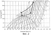
на фиг.2 - диаграммы температура-энтропия для диоксида углерода, на которой изображена возможная рабочая кривая замкнутого термодинамического цикла, осуществляемого тепловым насосом бытовой сушилки, показанной на фиг.1.figure 2 - temperature-entropy diagrams for carbon dioxide, which depicts a possible working curve of a closed thermodynamic cycle carried out by the heat pump of a household dryer, shown in figure 1.
Как показано на фиг.1, бытовая сушилка 1 для белья содержит наружный корпус 2 предпочтительно в форме параллелепипеда; предпочтительно цилиндрический колоколообразный сушильный барабан 3 для подлежащего сушилке белья, который установлен с возможностью осевого вращения внутри корпуса 2 и непосредственно обращен к отверстию 2а для загрузки и выгрузки белья, образованному в передней стенке корпуса 2; и дверцу 4, шарнирно установленную на передней стенке корпуса 2 для поворота в исходное положение и из исходного положения и закрывающую отверстие 2а в передней стенке для герметизации барабана 3.As shown in FIG. 1, a household clothes dryer 1 comprises an outer casing 2, preferably in the form of a parallelepiped; preferably a cylindrical bell-shaped drying drum 3 for the laundry to be dried, which is mounted axially rotatable inside the housing 2 and directly faces the hole 2a for loading and unloading the laundry formed in the front wall of the housing 2; and a door 4 pivotally mounted on the front wall of the housing 2 to rotate to its original position and from its original position and closing a hole 2a in the front wall to seal the drum 3.
В частности, в приведенном примере сушильный барабан 3 расположен внутри корпуса 2 горизонтально и опирается на несколько горизонтальных опорных роликов 5, которые установлены в корпусе 2 для обеспечения свободного вращения сушильного барабана 3 вокруг его продольной оси L.In particular, in the above example, the dryer drum 3 is horizontally located inside the housing 2 and is supported by several horizontal support rollers 5, which are installed in the housing 2 to provide free rotation of the dryer drum 3 about its longitudinal axis L.
Корпус 2, сушильный барабан 3, дверца 4 и опорные ролики 5 являются общеизвестными компонентами, поэтому подробно не описаны.The housing 2, the drying drum 3, the door 4 and the support rollers 5 are well-known components, therefore, are not described in detail.
Сушилка 1 для белья также содержит электродвигатель 6 для вращения по команде сушильного барабана 3 вокруг его продольной оси L внутри корпуса 2 и калорифер 7 с замкнутым контуром, установленный внутри корпуса 2 и обеспечивающий циркуляцию через сушильный барабан 3 потока горячего воздуха с низким уровнем влажности, который протекает через расположенное внутри барабана 3 белье и быстро сушит его.The clothes dryer 1 also includes an electric motor 6 for rotation on the command of the dryer drum 3 around its longitudinal axis L inside the cabinet 2 and a closed-circuit air heater 7 installed inside the cabinet 2 and allowing a low humidity stream of hot air to circulate through the dryer drum 3, which flows through the laundry located inside the drum 3 and quickly dries it.
В частности, калорифер 7 с замкнутым контуром обеспечивает отбор воздуха из сушильного барабана 3, удаление избыточной влаги из выходящего из сушильного барабана 3 горячего воздуха, нагрев осушенного воздуха до заданной температуры, обычно превышающей температуру воздуха, выходящего из сушильного барабана 3, и подачу нагретого осушенного воздуха назад в сушильный барабан 3, в котором воздух проходит через белье, обеспечивая его быструю сушку.In particular, the closed-circuit air heater 7 allows air to be taken out of the dryer drum 3, to remove excess moisture from the hot air exiting the dryer drum 3, to heat the dried air to a predetermined temperature, usually above the temperature of the air exiting the dryer drum 3, and to supply the heated, dried air back to the dryer drum 3, in which air passes through the laundry, providing quick drying.
Другими словами, калорифер 7 с замкнутым контуром обеспечивает непрерывное осушение и нагрев воздуха, циркулирующего внутри сушильного барабана 3, для быстрой сушки белья внутри барабана и содержит:In other words, the closed-circuit air heater 7 provides continuous drying and heating of the air circulating inside the dryer drum 3 for quick drying of the laundry inside the drum and contains:
- трубопровод 8 рециркуляции воздуха, два конца которого соединены с сушильным барабаном 3 с его противоположных сторон;- air recirculation pipe 8, the two ends of which are connected to the drying drum 3 from its opposite sides;
- центробежный вентилятор 9 или другой воздушный циркуляционный насос, установленный в трубопроводе 8 для создания внутри него воздушного потока f, протекающего в сушильный барабан 3 и проходящего через белье внутри барабана 3;- a centrifugal fan 9 or another air circulation pump installed in the pipe 8 to create an air stream f inside it, flowing into the dryer drum 3 and passing through the laundry inside the drum 3;
- тепловой насос 10, выполненный с возможностью быстрого охлаждения выходящего из сушильного барабана 3 воздушного потока f для конденсации избыточной влаги в воздушном потоке f, а затем быстрого нагрева воздушного потока f, возвращающегося обратно в сушильный барабан 3, чтобы входящий в сушильный барабан 3 воздушный поток быстро нагревался до температуры, превышающей температуру выходящего из сушильного барабана воздушного потока, или равной этой температуре.a heat pump 10 configured to rapidly cool the air stream f leaving the dryer drum 3 to condense excess moisture in the air stream f, and then quickly heat the air stream f returning to the dryer drum 3 so that the air stream entering the dryer drum 3 quickly heated to a temperature exceeding or equal to the temperature of the air stream leaving the dryer drum.
В частности, в показанном примере входной конец трубопровода 8 рециркуляции выполнен за одно целое с дверцей 4 и обращен к переднему отверстию сушильного барабана 3. Торцевая стенка 3а сушильного барабана 3 является перфорированной или, по меньшей мере, может пропускать воздух и позволяет воздуху проходить в барабан 3. Выпускной конец трубопровода 8 рециркуляции герметично соединен с торцевой стенкой 3а сушильного барабана 3.In particular, in the example shown, the inlet end of the recirculation pipe 8 is integrally formed with the door 4 and faces the front opening of the dryer drum 3. The end wall 3a of the dryer drum 3 is perforated or, at least, can pass air and allow air to enter the drum 3. The outlet end of the recirculation pipe 8 is hermetically connected to the end wall 3a of the drying drum 3.
Что касается электрического центробежного вентилятора 9, то он предназначен для создания воздушного потока f, протекающего по трубопроводу 8 рециркуляции от его впускного конца, т.е. от дверцы 4, к его выпускному концу, т.е. к перфорированной торцевой стенке 3а сушильного барабана 3.As for the electric centrifugal fan 9, it is intended to create an air stream f flowing through the recirculation pipe 8 from its inlet end, i.e. from door 4 to its outlet end, i.e. to the perforated end wall 3a of the drying drum 3.
Показанный на фиг.1 тепловой насос 10 действует таким же образом, как и обычный тепловой насос, который обеспечивает передачу тепла от одной среды к другой, используя промежуточный газообразный хладагент, подвергаемый действию замкнутого термодинамического цикла, термодинамические принципы которого широко известны и поэтому не описаны подробно.The heat pump 10 shown in FIG. 1 acts in the same way as a conventional heat pump, which transfers heat from one medium to another using an intermediate gaseous refrigerant exposed to a closed thermodynamic cycle, the thermodynamic principles of which are widely known and therefore not described in detail .
Тепловой насос содержит:The heat pump contains:
- устройство 11 сжатия хладагента, которое подвергает сжатию (например, адиабатическому) газообразный хладагент, чтобы давление и температура хладагента на выходе из устройства 11 сжатия были намного выше, чем на входе в него;- a refrigerant compression device 11 that compresses (for example adiabatic) gaseous refrigerant so that the pressure and temperature of the refrigerant at the outlet of the compression device 11 are much higher than at its inlet;
- первый теплообменник 12 воздух/хладагент, который расположен вдоль трубопровода 8 рециркуляции по потоку предпочтительно после центробежного вентилятора 9 и выполнен с возможностью обеспечения одновременного прохождения через него воздушного потока f из сушильного барабана 3 и хладагента, протекающего ко входу в устройство 11 сжатия, позволяя хладагенту, имеющему температуру ниже температуры воздушного потока f, поглощать тепло из воздушного потока f, вызывая тем самым конденсацию избыточной влаги в воздушном потоке f;- the first air / refrigerant heat exchanger 12, which is located along the recirculation pipe 8 preferably after the centrifugal fan 9 and is configured to simultaneously allow air flow f from the dryer drum 3 and the refrigerant flowing to the inlet of the compression device 11, allowing the refrigerant having a temperature below the temperature of the air stream f, absorb heat from the air stream f, thereby causing condensation of excess moisture in the air stream f;
- второй теплообменник 13 воздух/хладагент, который расположен вдоль трубопровода 8 рециркуляции по потоку после первого теплообменника 12 воздух/хладагент и выполнен с возможностью обеспечения одновременного прохождения через него воздушного потока f, направляющегося к сушильному барабану 3, и хладагента из выхода устройства 11 сжатия, позволяя хладагенту, имеющему температуру выше температуры воздушного потока f, отдавать тепло в воздушный поток f, быстро нагревая тем самым воздушный поток f до температуры, превышающей температуру воздушного потока f, выходящего из теплообменника 12 воздух/хладагент, и предпочтительно также превышающей температуру воздушного потока f, выходящего из сушильного барабана 3, или равной этой температуре;- a second air / refrigerant heat exchanger 13, which is located along the recirculation pipe 8 after the first air / refrigerant heat exchanger 12 and is configured to simultaneously pass through it an air stream f directed to the drying drum 3, and the refrigerant from the outlet of the compression device 11, allowing a refrigerant having a temperature above the temperature of the air stream f to transfer heat to the air stream f, thereby quickly heating the air stream f to a temperature higher than the air temperature th flow f, exiting from heat exchanger 12 air / coolant, and preferably also higher than the temperature of the airflow f, exiting from the drying drum 3, or equal to this temperature;
- дроссельный клапан или аналогичное устройство 14 расширения хладагента, которое обеспечивает, в противоположность устройству 11 сжатия, которое обеспечивает быстрое сжатие хладагента, быстрое расширение хладагента, поступающего из второго теплообменника 13 воздух/хладагент в первый теплообменник 12 воздух/хладагент, чтобы давление и температура хладагента, входящего в теплообменник 12 воздух/хладагент, было намного ниже давления и температуры хладагента, выходящего из теплообменника 13 воздух/хладагент, завершая тем самым замкнутый термодинамический цикл.- a throttle valve or similar refrigerant expansion device 14, which provides, in contrast to the compression device 11, which provides quick compression of the refrigerant, rapid expansion of the refrigerant coming from the second air / refrigerant heat exchanger 13 to the first air / refrigerant heat exchanger 12, so that the pressure and temperature of the refrigerant entering the air / refrigerant heat exchanger 12 was much lower than the pressure and temperature of the refrigerant leaving the air / refrigerant heat exchanger 13, thereby completing the closed-loop term dynamic cycle.
Аналогично тепловым насосам обычных калориферов с замкнутым контуром устройство 11 сжатия хладагента, первый теплообменник 12 воздух/хладагент, второй теплообменник 13 воздух/хладагент и устройство 14 расширения хладагента соединены между собой соответствующими соединительными трубопроводами для образования замкнутого контура, позволяющего хладагенту, выходящему из выпускного отверстия устройства 11 сжатия, протекать последовательно через теплообменник 13 воздух/хладагент, устройство 14 расширения хладагента и теплообменник 12 воздух/хладагент перед возвратом к входу в устройство 11 сжатия.Similar to heat pumps of conventional closed-circuit air heaters, a refrigerant compression device 11, a first air / refrigerant heat exchanger 12, a second air / refrigerant heat exchanger 13 and a refrigerant expansion device 14 are connected to each other by corresponding connecting pipelines to form a closed circuit allowing the refrigerant leaving the device outlet 11, flow sequentially through an air / refrigerant heat exchanger 13, a refrigerant expansion device 14, and an air / x heat exchanger 12 adagent before returning to the inlet of compressing device 11.
Кроме того, аналогично тепловому насосу калорифера с замкнутым контуром, описанному в документе US 2005086827, в тепловом насосе 10 сушилки 1 используется в качестве хладагента диоксид углерода, но в отличие от любой другой бытовой сушилки для белья тепловой насос 10 предназначен для поддержания всего хладагента, т.е. диоксида углерода, в газообразном состоянии при всех термодинамических превращениях, образующих замкнутый термодинамический цикл, осуществляемый тепловым насосом 10.In addition, similar to the closed-circuit heat exchanger heat pump described in US2005086827, the heat pump 10 of dryer 1 uses carbon dioxide as a refrigerant, but unlike any other household dryer, the heat pump 10 is designed to maintain all the refrigerant, t .e. carbon dioxide in a gaseous state during all thermodynamic transformations forming a closed thermodynamic cycle carried out by the heat pump 10.
Другими словами, устройство 11 сжатия хладагента, первый теплообменник 12 воздух/хладагент, второй теплообменник 13 воздух/хладагент и устройство 14 расширения хладагента образуют конструкцию, препятствующую фазовому превращению диоксида углерода (из однофазного состояния в двухфазное состояние) по всему замкнутому контуру, образованному устройством 11 сжатия хладагента, первым теплообменником 12 воздух/хладагент, вторым теплообменником 13 воздух/хладагент и устройством 14 расширения хладагента.In other words, the refrigerant compression device 11, the first air / refrigerant heat exchanger 12, the second air / refrigerant heat exchanger 13 and the refrigerant expansion device 14 form a structure that prevents the phase conversion of carbon dioxide (from a single-phase state to a two-phase state) throughout the closed loop formed by the device 11 compressing the refrigerant, the first air / refrigerant heat exchanger 12, the second air / refrigerant heat exchanger 13, and the refrigerant expansion device 14.
В частности, как показано на фиг.2, устройство 11 сжатия хладагента, первый теплообменник 12 воздух/хладагент, второй теплообменник 13 воздух/хладагент и устройство 14 расширения хладагента выполнены таким образом, что все термодинамические превращения, образующие замкнутый термодинамический цикл, осуществляемый тепловым насосом 10, т.е. сжатие хладагента а-b, охлаждение хладагента b-с, быстрое расширение хладагента c-d и нагрев хладагента d-a, остаются выше кривой насыщения S диаграммы температура-энтропия для диоксида углерода.In particular, as shown in FIG. 2, the refrigerant compression device 11, the first air / refrigerant heat exchanger 12, the second air / refrigerant heat exchanger 13 and the refrigerant expansion device 14 are configured so that all thermodynamic transformations forming a closed thermodynamic cycle carried out by the heat pump 10, i.e. Compression of refrigerant a-b, cooling of refrigerant b-c, rapid expansion of refrigerant c-d and heating of refrigerant d-a remain above the saturation curve S of the temperature-entropy diagram for carbon dioxide.
Другими словами, замкнутый термодинамический цикл, осуществляемый тепловым насосом 10, является полностью сверхкритическим замкнутым термодинамическим циклом, и диоксид углерода имеет сверхкритическое давление как на стороне высокого давления (т.е. теплообменник 13 воздух/хладагент), так и на стороне низкого давления (т.е. теплообменник 12 воздух/хладагент) теплового насоса 10.In other words, the closed thermodynamic cycle carried out by the heat pump 10 is a completely supercritical closed thermodynamic cycle, and carbon dioxide has supercritical pressure both on the high pressure side (i.e., the air / refrigerant heat exchanger 13) and on the low pressure side (t .e. heat exchanger 12 air / refrigerant) heat pump 10.
Как показано на фиг.1, подобно любому другому бытовому электроприбору, представленному в последнее время на рынке, бытовая сушилка 1 для белья содержит центральный электронный блок 15 управления, который управляет электродвигателем 6, центробежным вентилятором 9 и тепловым насосом 10, или, предпочтительно, устройством 11 сжатия, заранее определенным способом согласно данным в запоминающем устройстве с целью выполнения цикла сушки, задаваемого пользователем.As shown in FIG. 1, like any other household appliance recently introduced on the market, a household dryer 1 includes a central electronic control unit 15 that controls an electric motor 6, a centrifugal fan 9 and a heat pump 10, or, preferably, a device 11, in a predetermined manner according to data in a storage device for the purpose of performing a drying cycle set by a user.
Общий принцип работы бытовой сушилки 1 для белья понятен из вышеприведенного описания и не требует дополнительных пояснений.The general principle of operation of the household clothes dryer 1 is clear from the above description and does not require additional explanation.
Использование теплового насоса, выполняющего полностью сверхкритический замкнутый термодинамический цикл с диоксидом углерода в качестве хладагента, имеет много неожидаемых преимуществ. Лабораторные испытания фактически выявили, что температурные профили газообразного диоксида углерода как на стороне высокого давления (т.е. теплообменник 13 воздух/хладагент), так и на стороне низкого давления (т.е. теплообменник 12 воздух/хладагент) теплового насоса 10 точно соответствуют динамике изменений температуры воздуха воздушного потока f, циркулирующего в двух соседних секциях трубопровода 8 рециркуляции, тем самым значительно повышая энергетический КПД процесса передачи тепла.Using a heat pump that runs a fully supercritical closed thermodynamic cycle with carbon dioxide as a refrigerant has many unexpected advantages. Laboratory tests have actually revealed that the temperature profiles of carbon dioxide gas on both the high pressure side (i.e., air / refrigerant heat exchanger 13) and the low pressure side (i.e. air / refrigerant heat exchanger 12) of the heat pump 10 exactly match the dynamics of changes in air temperature of the air flow f circulating in two adjacent sections of the recirculation pipe 8, thereby significantly increasing the energy efficiency of the heat transfer process.
Это повышение энергетического КПД ведет к значительному повышению общей энергетической эффективности сушилки для белья, существенно снижая расход энергии.This increase in energy efficiency leads to a significant increase in the overall energy efficiency of the clothes dryer, significantly reducing energy consumption.
Фактически, при таком же количестве переданного тепла тепловой насос 10 работает при большем значении давления хладагента на стороне низкого давления теплового насоса 10, тем самым существенно снижая расход энергии для устройства 11 сжатия хладагента.In fact, with the same amount of heat transferred, the heat pump 10 operates at a higher refrigerant pressure on the low pressure side of the heat pump 10, thereby significantly reducing energy consumption for the refrigerant compression device 11.
Разумеется, в бытовую сушилку 1 для белья могут быть внесены изменения без выхода за объем изобретения.Of course, changes may be made to the household dryer 1 without departing from the scope of the invention.
Например, бытовая сушилка 1 для белья может быть объединена со стиральной машиной, позволяя получить машину для стирки/сушки белья.For example, a household clothes dryer 1 can be combined with a washing machine, allowing you to get a machine for washing / drying clothes.
В этом случае сушильный барабан 3 установлен с возможностью осевого вращения в герметичном, предпочтительно цилиндрическом баке или камере сушилки для белья, который установлен по существу горизонтально внутри корпуса 2 и непосредственно обращен к отверстию 2а для загрузки и выгрузки белья, образованному в передней стенке корпуса 2. При этом на передней стенке корпуса 2 шарнирно установлена дверца 4 для поворота в исходное положение и из исходного положения, которая может закрывать отверстие 2а в передней стенке для герметизации бака для сушки белья.In this case, the dryer drum 3 is mounted axially rotatable in a sealed, preferably cylindrical tub or chamber of the clothes dryer, which is mounted essentially horizontally inside the cabinet 2 and directly faces the hole 2a for loading and unloading the laundry formed in the front wall of the cabinet 2. At the same time, a door 4 is pivotally mounted on the front wall of the housing 2 to rotate to the initial position and from the initial position, which can close the hole 2a in the front wall to seal the tank for ears of linen.
Claims (8)
Applications Claiming Priority (2)
| Application Number | Priority Date | Filing Date | Title |
|---|---|---|---|
| EP07121051A EP2060671B1 (en) | 2007-11-19 | 2007-11-19 | Home laundry drier |
| EP07121051.2 | 2007-11-19 |
Publications (2)
| Publication Number | Publication Date |
|---|---|
| RU2010124943A RU2010124943A (en) | 2011-12-27 |
| RU2467110C2 true RU2467110C2 (en) | 2012-11-20 |
Family
ID=39266568
Family Applications (1)
| Application Number | Title | Priority Date | Filing Date |
|---|---|---|---|
| RU2010124943/12A RU2467110C2 (en) | 2007-11-19 | 2008-11-17 | Household dryer for clothes |
Country Status (6)
| Country | Link |
|---|---|
| EP (1) | EP2060671B1 (en) |
| AT (1) | ATE472629T1 (en) |
| DE (1) | DE602007007489D1 (en) |
| PL (1) | PL2060671T3 (en) |
| RU (1) | RU2467110C2 (en) |
| WO (1) | WO2009065538A1 (en) |
Families Citing this family (11)
| Publication number | Priority date | Publication date | Assignee | Title |
|---|---|---|---|---|
| EP2147999A1 (en) * | 2008-07-24 | 2010-01-27 | Electrolux Home Products Corporation N.V. | Home laundry drier |
| EP2479337B1 (en) * | 2011-01-24 | 2013-08-07 | Electrolux Home Products Corporation N.V. | Household appliance for drying objects |
| EP2527519B1 (en) | 2011-05-26 | 2018-12-12 | Electrolux Home Products Corporation N.V. | Articles treatment apparatus having heat pump system with safety element |
| EP2527520B1 (en) | 2011-05-26 | 2018-12-26 | Electrolux Home Products Corporation N.V. | Articles treatment apparatus having heat pump system with safety element |
| EP2527521A1 (en) * | 2011-05-26 | 2012-11-28 | Electrolux Home Products Corporation N.V. | A heat pump laundry dryer |
| EP2527522B1 (en) * | 2011-05-26 | 2013-12-25 | Electrolux Home Products Corporation N.V. | A heat pump laundry dryer |
| EP2527518B1 (en) | 2011-05-26 | 2017-05-03 | Electrolux Home Products Corporation N.V. | Laundry treatment apparatus having heat pump system with safety element |
| EP2551401A1 (en) * | 2011-07-28 | 2013-01-30 | Electrolux Home Products Corporation N.V. | A heat pump system for a laundry dryer |
| EP2551402A1 (en) * | 2011-07-28 | 2013-01-30 | Electrolux Home Products Corporation N.V. | A heat pump system for a laundry dryer |
| EP2592184A1 (en) * | 2011-11-08 | 2013-05-15 | Electrolux Home Products Corporation N.V. | Rotary-drum laundry dryer |
| KR102834821B1 (en) * | 2019-03-26 | 2025-07-17 | 삼성전자주식회사 | Clothes drying apparatus and controlling method thereof |
Citations (3)
| Publication number | Priority date | Publication date | Assignee | Title |
|---|---|---|---|---|
| EP1584731A2 (en) * | 2004-03-15 | 2005-10-12 | SANYO ELECTRIC Co., Ltd. | Dry cleaner and corresponding drying machine |
| EP1614976A1 (en) * | 2003-04-02 | 2006-01-11 | Matsushita Electric Industrial Co., Ltd. | Drying device and method of operation therefor |
| EP1632736A2 (en) * | 2004-09-07 | 2006-03-08 | SANYO ELECTRIC Co., Ltd. | Heat pump device and drying machine |
Family Cites Families (2)
| Publication number | Priority date | Publication date | Assignee | Title |
|---|---|---|---|---|
| JP3825772B2 (en) * | 2003-09-05 | 2006-09-27 | 三洋電機株式会社 | Dryer |
| WO2005075728A1 (en) * | 2004-02-04 | 2005-08-18 | Matsushita Electric Industrial Co., Ltd. | Drying apparatus and operating method thereof |
-
2007
- 2007-11-19 EP EP07121051A patent/EP2060671B1/en not_active Not-in-force
- 2007-11-19 AT AT07121051T patent/ATE472629T1/en not_active IP Right Cessation
- 2007-11-19 PL PL07121051T patent/PL2060671T3/en unknown
- 2007-11-19 DE DE602007007489T patent/DE602007007489D1/en active Active
-
2008
- 2008-11-17 WO PCT/EP2008/009699 patent/WO2009065538A1/en not_active Ceased
- 2008-11-17 RU RU2010124943/12A patent/RU2467110C2/en active
Patent Citations (3)
| Publication number | Priority date | Publication date | Assignee | Title |
|---|---|---|---|---|
| EP1614976A1 (en) * | 2003-04-02 | 2006-01-11 | Matsushita Electric Industrial Co., Ltd. | Drying device and method of operation therefor |
| EP1584731A2 (en) * | 2004-03-15 | 2005-10-12 | SANYO ELECTRIC Co., Ltd. | Dry cleaner and corresponding drying machine |
| EP1632736A2 (en) * | 2004-09-07 | 2006-03-08 | SANYO ELECTRIC Co., Ltd. | Heat pump device and drying machine |
Also Published As
| Publication number | Publication date |
|---|---|
| WO2009065538A1 (en) | 2009-05-28 |
| DE602007007489D1 (en) | 2010-08-12 |
| RU2010124943A (en) | 2011-12-27 |
| ATE472629T1 (en) | 2010-07-15 |
| PL2060671T3 (en) | 2010-12-31 |
| EP2060671B1 (en) | 2010-06-30 |
| EP2060671A1 (en) | 2009-05-20 |
Similar Documents
| Publication | Publication Date | Title |
|---|---|---|
| RU2467110C2 (en) | Household dryer for clothes | |
| CN102272373B (en) | Laundry washing and drying machine | |
| US9976242B2 (en) | Clothes treating apparatus with a heat pump cycle | |
| US8082677B2 (en) | Home laundry drier | |
| JP4889545B2 (en) | Drying apparatus and washing and drying machine equipped with this apparatus | |
| KR101613966B1 (en) | Clothes treating apparatus | |
| US10184206B2 (en) | Clothes treating apparatus and control method thereof | |
| JP2005024113A (en) | Dryer | |
| US11821135B2 (en) | Laundry treating appliance with a condenser | |
| CN103348056A (en) | household clothes dryer | |
| JP2003265880A (en) | Washing/drying machine | |
| EP2692940A1 (en) | Method for drying laundry in a laundry drying machine and laundry drying machine | |
| RU2496935C2 (en) | Household drying machine for linen | |
| RU2452804C2 (en) | Household drying device for clothes | |
| JP2008067742A (en) | Clothes dryer | |
| JP5268527B2 (en) | Heat pump dryer | |
| JP7488035B2 (en) | Clothes dryer | |
| JP6092004B2 (en) | Clothes dryer | |
| JP3956825B2 (en) | Washing and drying machine | |
| JP2006181219A (en) | Dryer | |
| US20120060387A1 (en) | Heat exchanger for a heat pump laundry dryer | |
| JP3973463B2 (en) | Washing and drying machine | |
| JP3973464B2 (en) | Washing and drying machine | |
| JP2018183402A (en) | Clothes dryer | |
| JP2018114039A (en) | Clothes dryer |