RU2465606C1 - Adaptive method for rapid remote measurement of wind speed and direction - Google Patents
Adaptive method for rapid remote measurement of wind speed and direction Download PDFInfo
- Publication number
- RU2465606C1 RU2465606C1 RU2011126903/28A RU2011126903A RU2465606C1 RU 2465606 C1 RU2465606 C1 RU 2465606C1 RU 2011126903/28 A RU2011126903/28 A RU 2011126903/28A RU 2011126903 A RU2011126903 A RU 2011126903A RU 2465606 C1 RU2465606 C1 RU 2465606C1
- Authority
- RU
- Russia
- Prior art keywords
- atmosphere
- wind speed
- scattering
- wind
- volumes
- Prior art date
Links
Images


Abstract

Description
Изобретение относится к измерительной технике и может быть использовано, в частности, в прикладной метеорологии для оперативного дистанционного измерения скорости и направления ветра.The invention relates to measuring technique and can be used, in particular, in applied meteorology for operational remote measurement of wind speed and direction.
Известны способы измерения скорости газового потока и атмосферного ветра, основанные на регистрации (контактным или дистанционным методом) случайных реализаций сигналов в двух точках потока и дальнейшем анализе измеренных случайных реализациий или результатов их корреляционной обработки (см, например, [1-6]). Для оперативного дистанционного измерения скорости и направления атмосферного ветра перспективными являются методы лазерного дистанционного зондирования [2-6].Known methods for measuring the velocity of a gas stream and atmospheric wind, based on the registration (by contact or remote sensing) of random realizations of signals at two points of the flow and further analysis of the measured random realizations or the results of their correlation processing (see, for example, [1-6]). For operational remote measurement of the speed and direction of atmospheric wind, laser remote sensing methods are promising [2-6].
Наиболее близким к предлагаемому способу является способ оперативного дистанционного определения скорости ветра с помощью лидара [2], заключающийся в том, что атмосферу облучают двумя зондирующими пучками, распространяющимися с малым угловым расстоянием между ними, регистрируют сигналы из рассеивающих объемов в атмосфере, при этом количество рассеивающих объемов n>2 (вид сверху для варианта четырех рассеивающих объемов показан на фиг.1) выбирают исходя из требуемой точности Δφ определения направления ветра 
![]()
![]()
![]()
![]()
![]()
![]()
Недостаток способа [2] - из-за использования только двух лазерных лучей расстояния (измерительные базы) между рассеивающим объемом 1 и рассеивающими объемами 2…i…n являются неодинаковыми (это хорошо видно из фиг.1: расстояния d2, d3 и d4 существенно различаются между собой) и независящими от характеристик атмосферы. Выбор измерительных баз неодинаковыми и независящими от характеристик атмосферы может приводить к существенным ошибкам определения скорости ветра.The disadvantage of the method [2] - due to the use of only two laser beams, the distances (measuring bases) between the
Повысить точность можно тем, что до начала измерений атмосферу зондируют для определения размеров аэрозольных неоднородностей атмосферы, затем облучают пучком, сканирующим в горизонтальной плоскости в пределах небольшого угла (единицы градусов), регистрируют сигналы из рассеивающих объемов в атмосфере, при этом количество рассеивающих объемов выбирают исходя из требуемой точности Δφ определения направления ветра: 
![]()
![]()
![]()
![]()
![]()
![]()
![]()
![]()
Для измерения характеристик атмосферных неоднородностей проводят предварительное (до начала измерений) зондирование атмосферы вдоль лазерного луча (центрального луча а на фиг.2). Использование лазерного источника с короткими импульсами и сканирования узкого лазерного пучка в горизонтальной плоскости позволяет реализовать измерения для измерительных баз с произвольной ориентацией и произвольного размера и адаптивно (в соответствии с размерами аэрозольных неоднородностей атмосферы и скоростью ветра на момент измерений) изменять размер измерительных баз при изменении атмосферных условий.To measure the characteristics of atmospheric inhomogeneities, preliminary (prior to measurement) sensing of the atmosphere is carried out along the laser beam (central beam a in FIG. 2). Using a laser source with short pulses and scanning a narrow laser beam in the horizontal plane allows measurements to be made for measuring bases with arbitrary orientation and arbitrary size and adaptively (in accordance with the size of the aerosol inhomogeneities of the atmosphere and wind speed at the time of measurement) to change the size of the measuring bases when changing atmospheric conditions.
На фиг.2 показан вид сверху для предлагаемой схемы зондирования; а, б, в, г - положения в пространстве сканирующего лазерного луча, для которых расстояния между рассеивающим объемом 1 и рассеивающими объемами 2НВ1, 2НВ2 и 2НВ3 (на рисунке показаны три из n рассеивающих объемов 2HB1…2HBi…2HBn) одинаковы и равны некоторой оптимальной величине, определяемой условиями на атмосферной трассе.Figure 2 shows a top view of the proposed sensing scheme; a, b, c, d - the positions in the space of the scanning laser beam for which the distances between the
Наличие отличительных признаков (предварительное зондирование для определения размеров аэрозольных неоднородностей атмосферы и использование сканирующего пучка для адаптивного изменения измерительных баз) указывает на соответствие критерию "новизна".The presence of distinctive features (preliminary sounding to determine the size of aerosol inhomogeneities of the atmosphere and the use of a scanning beam for adaptively changing the measurement bases) indicates compliance with the criterion of "novelty."
Указанные отличительные признаки неизвестны в научно-технической и патентной литературе и поэтому предложенное техническое решение (как совокупность реализованных указанных признаков) соответствует критерию "изобретательский уровень".These distinctive features are unknown in the scientific, technical and patent literature, and therefore, the proposed technical solution (as a combination of these features) meets the criterion of "inventive step".
Устройство, реализующее предлагаемый способ, работает следующим образом.A device that implements the proposed method works as follows.
Лидар содержит лазерный источник излучения, передающую оптическую систему, приемную оптическую систему, фотоприемник и блок обработки. Излучение лазерного источника проходит передающую оптическую систему, которая формирует зондирующий пучок, сканирующий в горизонтальной плоскости в пределах небольшого (единицы градусов) угла.The lidar contains a laser radiation source, a transmitting optical system, a receiving optical system, a photodetector and a processing unit. The radiation from the laser source passes through the transmitting optical system, which forms a probe beam scanning in the horizontal plane within a small (unit of degrees) angle.
Аэрозоль, всегда содержащийся в атмосфере, рассеивает излучение в сторону лидара (размеры рассеивающих объемов определяются углом расходимости зондирующих пучков, их расстоянием от лидара и длительностью импульса источника излучения).The aerosol always contained in the atmosphere scatters the radiation toward the lidar (the sizes of the scattering volumes are determined by the divergence angle of the probe beams, their distance from the lidar and the pulse duration of the radiation source).
Принимаемое излучение проходит через приемную оптическую систему, регистрируется фотоприемником и поступает в блок обработки для определения направления и величины скорости ветра.The received radiation passes through the receiving optical system, is recorded by the photodetector and enters the processing unit to determine the direction and magnitude of the wind speed.
В блоке обработки лидара проводят последовательно следующие операции.The following operations are carried out sequentially in the lidar processing unit.
1. Определяют (по результатам предварительного зондирования атмосферы вдоль лазерного луча (центрального луча а на фиг.2)) размеры аэрозольных неоднородностей атмосферы [4,5].1. Determine (according to the results of preliminary sounding of the atmosphere along the laser beam (central beam a in figure 2)) the size of the aerosol inhomogeneities of the atmosphere [4,5].
2. Определяют для времени наблюдения tH оптимальный размер d измерительных баз для существующих условий на атмосферной трассе.2. Determine for the observation time t H the optimal size d of the measuring bases for the existing conditions on the atmospheric path.
3. Определяют (по результатам измерений в течение времени наблюдения tH) взаимно-структурные функции ![]()
![]()
4. Определяют положение минимумов τi взаимно-структурных функций S1,2i(τ), i=1…n и значения ![]()
![]()
5. Определяют минимальное (среди найденных значений ![]()
![]()
![]()
![]()
6. За направление атмосферного ветра принимают направление между рассеивающим объемом 1 и объемом 2HBi min с наименьшим минимальным значением ![]()
![]()
7. Величину и знак скорости ветра определяют по положению τi min минимума взаимно-структурной функции ![]()
![]()

В результате работы блока обработки формируют (с заданной дискретностью) массив данных о величине и направлении ветра вдоль трассы зондирования.As a result of the work of the processing unit, an array of data on the magnitude and direction of the wind along the sounding path is formed (with a given discreteness).
Для оценки работоспособности предлагаемого способа оперативного измерения скорости и направления атмосферного ветра проводилось математическое моделирование.To assess the performance of the proposed method for the operational measurement of the speed and direction of the atmospheric wind, mathematical modeling was carried out.
Выбор оптимального размера d измерительной базы для корреляционного метода измерения скорости ветра обсуждался в [5]. Показано, что оптимальным является выбор измерительной базы d порядка размера аэрозольных неоднородностей атмосферы. Однако этот вывод был сделан для достаточно больших времен наблюдения, когда аэрозольные неоднородности могут разрушаться и, пройдя первую точку измерительной базы, могут не дойти до второй точки измерительной базы.The choice of the optimal size d of the measuring base for the correlation method for measuring wind speed was discussed in [5]. It is shown that the optimal choice is the measuring base d of the order of the size of aerosol inhomogeneities of the atmosphere. However, this conclusion was made for sufficiently large observation times, when aerosol inhomogeneities can collapse and, having passed the first point of the measuring base, may not reach the second point of the measuring base.
Вопрос о выборе оптимального размера измерительной базы в условиях оперативных измерений (когда время измерения мало - единицы секунд) остается не ясным. В этом случае аэрозольные неоднородности атмосферы в большинстве случаев не успевают разрушаться [5], проходя от первой до второй точки измерительной базы (для малой измерительной базы), и оптимальный размер измерительной базы должен определяться не только размером аэрозольных неоднородностей, но и временем наблюдения, требуемой минимальной измеряемой скоростью ветра и отношением сигнал/шум. При этом сами размеры аэрозольные неоднородности атмосферы (и время их жизни, зависящее от размера неоднородностей) изменяются в широком диапазоне в зависимости от атмосферных условий [5]. Поэтому необходимым является предварительное зондирование атмосферы для оперативной оценки размера аэрозольных неоднородностей вдоль трассы зондирования.The question of choosing the optimal size of the measuring base in the conditions of operational measurements (when the measurement time is short - a few seconds) remains unclear. In this case, the aerosol inhomogeneities of the atmosphere in most cases do not have time to collapse [5], passing from the first to the second point of the measuring base (for a small measuring base), and the optimal size of the measuring base should be determined not only by the size of the aerosol inhomogeneities, but also by the observation time required minimum measured wind speed and signal to noise ratio. Moreover, the sizes of aerosol inhomogeneities of the atmosphere (and their lifetime, depending on the size of the inhomogeneities) vary over a wide range depending on atmospheric conditions [5]. Therefore, preliminary sounding of the atmosphere is necessary for the rapid estimation of the size of aerosol inhomogeneities along the sounding path.
В наиболее простом случае, когда направление ветра известно, единственным параметром, который надо определить, является скорость ветра. На фиг.3 для этого случая показана геометрическая схема измерений корреляционного ветрового лидара с малой измерительной базой, короткими зондирующими импульсами и сканирующим в горизонтальной плоскости лазерным пучком. На фиг.3 Л - лидар; НВ - направление ветра; а, б, в, г - положения в пространстве сканирующего лазерного луча; 1 - положение первой точки измерительной базы; 2, 3, 4 - возможные положения второй точки измерительной базы.In the simplest case, when the direction of the wind is known, the only parameter to be determined is the wind speed. Figure 3 for this case shows a geometric diagram of the measurements of the correlation wind lidar with a small measuring base, short probing pulses and a scanning laser beam in a horizontal plane. In Fig.3 L - lidar; HB - wind direction; a, b, c, d - position in the space of the scanning laser beam; 1 - position of the first point of the measuring base; 2, 3, 4 - possible positions of the second point of the measuring base.
Лидар Л облучает атмосферу узким лазерным пучком, сканирующим в горизонтальной плоскости в пределах некоторого небольшого угла сканирования (порядка единиц градусов). Лазерный импульс (для каждого положения оптической оси лидара при сканировании) рассеивается на атмосферном аэрозоле (во всех направлениях, в том числе и в направлении назад на лидар) и поступает в приемную систему лидара. Принимаемое излучение стробируется по дальности, так что регистрируемые значения сигналов (для каждого положения оптической оси лидара при сканировании) соответствуют сигналам от последовательности локальных объемов измерения вдоль соответствующей (а, б, в, г, …) трассы зондирования.Lidar L irradiates the atmosphere with a narrow laser beam scanning in the horizontal plane within a certain small scanning angle (of the order of units of degrees). The laser pulse (for each position of the optical axis of the lidar during scanning) is scattered on the atmospheric aerosol (in all directions, including in the direction back to the lidar) and enters the lidar receiving system. The received radiation is gated in range, so that the recorded signal values (for each position of the optical axis of the lidar during scanning) correspond to signals from a sequence of local measurement volumes along the corresponding (a, b, c, d, ...) sensing paths.
При известном направлении ветра измерительная база должна располагаться вдоль этого направления [5]. Пусть первая точки измерительной базы 1 находится на некотором расстоянии от лидара. Тогда вторая точки измерительной базы должна находиться на линии НВ на некотором оптимальном (с точки зрения точности измерения скорости ветра) расстоянии от точки 1 (в одной из точек 2, 3, 4 …).With a known wind direction, the measuring base should be located along this direction [5]. Let the first point of the
Для определения оптимального размера измерительной базы проводилось математическое моделирование и исследование зависимости погрешности измерения скорости ветра от размера измерительной базы при известном направлении ветра.To determine the optimal size of the measuring base, mathematical modeling was carried out and the dependence of the error of measuring wind speed on the size of the measuring base with a known wind direction was studied.
Для математического моделирования был создан комплекс программ, имитирующий работу лазерного измерителя скорости атмосферного ветра. Использовалась гипотеза замороженности неоднородностей атмосферы во время проведения измерений, т.е. считалось, что неоднородности переносятся в атмосфере под действием среднего ветра, не изменяя своей формы. В этом случае корреляционный метод определения скорости ветра V может быть упрощен [5]:For mathematical modeling, a set of programs was created that simulated the operation of a laser measuring instrument of atmospheric wind speed. The hypothesis of frozen atmospheric inhomogeneities was used during measurements, i.e. It was believed that inhomogeneities are transported in the atmosphere under the influence of the average wind, without changing their shape. In this case, the correlation method for determining the wind speed V can be simplified [5]:
![]()
![]()
где d - измерительная база (расстояние от точки 1 до второй точки базы (одной из точек 2, 3, 4 …) вдоль линии НВ), τ - временной сдвиг максимума взаимной корреляционной функции двух сигналов, регистрируемых от рассеивающих объемов атмосферы в точке 1 и второй точке базы.where d is the measuring base (the distance from
Использование вместо корреляционной функции структурной функции дает меньшие погрешности измерения скорости ветра, поэтому при проведении моделирования для определения τ была использована структурная функция сигналов (временной сдвиг τ соответствует минимуму структурной функции двух сигналов, регистрируемых от рассеивающих объемов атмосферы).The use of a structural function instead of a correlation function gives smaller errors in measuring wind speed; therefore, in order to determine τ, the signal structural function was used (the time shift τ corresponds to the minimum structural function of two signals recorded from scattering atmospheric volumes).
Математическое моделирование проводилось для разных размеров аэрозольных неоднородностей атмосферы, при различном отношении сигнал/шум в широком диапазоне скоростей ветра.Mathematical modeling was carried out for different sizes of aerosol inhomogeneities of the atmosphere, with different signal-to-noise ratios in a wide range of wind speeds.
На фиг.4 представлен пример зависимости средних (по 500 реализациям полей аэрозольных неоднородностей атмосферы) модулей погрешностей измерения скорости ветра ΔV от величины измерительной базы d для размера аэрозольных неоднородностей 5 м (измерительная база вдоль направления ветра). Время измерения составляло 5 с. Параметры атмосферных неоднородностей соответствовали условиям горизонтальной трассы в приземном слое атмосферы. Отношение сигнал/шум равно 5. На рисунке: 1 - скорость ветра 4 м/с, 2-8 м/с, 3-12 м/с.Figure 4 shows an example of the dependence of the average (over 500 realizations of the fields of aerosol inhomogeneities of the atmosphere) error modules for measuring wind speed ΔV on the size of the measuring base d for the size of aerosol inhomogeneities of 5 m (measuring base along the wind direction). The measurement time was 5 s. The parameters of atmospheric inhomogeneities corresponded to the conditions of the horizontal path in the surface layer of the atmosphere. The signal-to-noise ratio is 5. In the figure: 1 - wind speed 4 m / s, 2-8 m / s, 3-12 m / s.
Результаты математического моделирования, приведенные на фиг.4, показывают, что наименьшие погрешности измерения скорости ветра получаются при выборе измерительной базы d~14 м.The results of mathematical modeling, shown in figure 4, show that the smallest errors in measuring wind speed are obtained when choosing a measuring base d ~ 14 m
Выбор необходимого размера измерительной базы при произвольном (известном) направлении ветра обеспечивается возможностью локализации в пространстве локальных объемов измерения за счет углового сканирования узкого лазерного пучка и использования лазера с короткими зондирующими импульсами.The choice of the required size of the measuring base with an arbitrary (known) wind direction is provided by the possibility of localizing in the space of local measurement volumes due to the angular scanning of a narrow laser beam and the use of a laser with short probe pulses.
В условиях реальных измерений нельзя заранее знать: справедлива или нет гипотеза замороженности неоднородностей атмосферы во время проведения измерений. Поэтому заранее нельзя определиться, какую измерительную базу лучше (в смысле обеспечения наименьших погрешностей измерения скорости ветра) использовать: базу, выбранную, как изложено выше (для условий замороженности неоднородностей), или базу, равную размеру аэрозольных неоднородностей атмосферы (для условий, когда аэрозольные неоднородности могут разрушаться за время наблюдения).Under real measurements, one cannot know in advance whether the hypothesis of frozen atmospheric inhomogeneities during measurements is valid or not. Therefore, it is impossible to determine in advance which measuring base is better (in the sense of ensuring the smallest errors in measuring wind speed) to use: a base selected as described above (for the conditions of frozen inhomogeneities), or a base equal to the size of aerosol inhomogeneities of the atmosphere (for conditions when aerosol inhomogeneities can be destroyed during the observation).
Однако этот вопрос можно решить оперативно в процессе измерений. Результаты проведенного математического моделирования показывают, что погрешности измерения скорости ветра зависят от некоторого параметра Λ=Δmin/d1/2, где Δmin - минимальное значение структурной функции реализации сигналов, измеренных в двух точках измерительной базы (т.е. значение структурной функции при наилучшем совмещении реализации сигналов, для которого определяется временной сдвиг, используемый для измерения скорости ветра); d - размер измерительной базы. Поэтому методика оперативного выбора измерительной базы может быть следующая.However, this issue can be resolved promptly during the measurement process. The results of mathematical modeling show that the errors in measuring wind speed depend on some parameter Λ = Δ min / d 1/2 , where Δ min is the minimum value of the structural function of the implementation of signals measured at two points of the measuring base (i.e., the value of the structural function with the best combination of the implementation of signals, for which the time shift used to measure wind speed is determined); d is the size of the measuring base. Therefore, the methodology for the operational selection of the measuring base can be as follows.
1. До начала измерений проводится зондирование атмосферы вдоль начального положения а оптической оси лидара. Полученная реализация сигнала (она определяется пространственной реализацией показателя обратного аэрозольного рассеяния атмосферы вдоль трассы а) используется для оценки характерного размера аэрозольных неоднородностей атмосферы.1. Prior to measurements, atmospheric sounding is carried out along the initial position a of the optical axis of the lidar. The obtained implementation of the signal (it is determined by the spatial realization of the index of backward aerosol scattering of the atmosphere along route a) is used to estimate the characteristic size of the aerosol inhomogeneities of the atmosphere.
2. Проводятся измерения реализации сигналов для измерительной базы А, выбранной, как изложено выше (по минимуму погрешностей измерения скорости ветра), и для измерительной базы Б, равной размеру аэрозольных неоднородностей атмосферы.2. Measurements are made of the implementation of the signals for the measuring base A, selected as described above (to minimize the errors in measuring wind speed), and for measuring base B, equal to the size of the aerosol inhomogeneities of the atmosphere.
3. Вычисляется параметр Λ для измерительной базы А и базы Б.3. The parameter Λ is calculated for measuring base A and base B.
4. Выбирается измерительная база, для которой параметр Λ меньше.4. A measurement base is selected for which the parameter Λ is less.
В Таблице 1 приведены результаты математического моделирования. Здесь показаны средние (по 500 реализациям полей аэрозольных неоднородностей атмосферы) модули погрешностей измерения скорости ветра ΔV для измерительной базы А (равной 14 м) и измерительной базы Б (равной размеру неоднородностей).Table 1 shows the results of mathematical modeling. Shown here are the average (over 500 realizations of the fields of aerosol inhomogeneities of the atmosphere) error modules for measuring wind speed ΔV for measuring base A (equal to 14 m) and measuring base B (equal to the size of inhomogeneities).
Таблица 1 получена для размера неоднородностей 5 м и для скоростей ветра V=4 м/с, V=8 м/с и V=12 м/с при отношении сигнал/шум (с/ш), равным 2, 5 и 50, и времени измерения 5 с. В скобках даны значения параметра Λ. Таблица 1 иллюстрирует преимущество выбора размера измерительной базы А над выбором измерительной базы Б при проведении оперативных измерений скорости ветра (в случае, когда неоднородности не разрушаются и переносятся в атмосфере под действием ветра). Видно, что по величине Λ можно судить о погрешностях измерения скорости ветра ΔV: база с меньшим Λ обеспечивает меньшие погрешности измерения скорости ветра.Table 1 was obtained for the size of inhomogeneities of 5 m and for wind speeds V = 4 m / s, V = 8 m / s and V = 12 m / s with a signal to noise ratio (s / w) of 2, 5 and 50, and measurement time 5 s. The values of the parameter Λ are given in parentheses. Table 1 illustrates the advantage of choosing the size of the measuring base A over the choice of measuring base B during operational measurements of wind speed (in the case when the inhomogeneities do not collapse and are transferred to the atmosphere under the influence of wind). It can be seen that by the value of Λ one can judge the errors in measuring wind speed ΔV: a base with a smaller Λ provides smaller errors in measuring wind speed.
В общем случае, когда направление ветра неизвестно, его надо определять совместно со скоростью ветра. Схема, которая может обеспечить одновременное оперативное измерение скорости и направления ветра, представлена на фиг.2. На фигуре: НВ1, НВ2, НВ3, … - направления измерительных баз, т.е. возможных направлений ветра (их число определяется требуемой точностью измерения направления ветра). Для каждого направления НВ1, НВ2, НВ3, … проводится цикл обработки результатов измерений описанный выше. За направление ветра принимается направление, для которого реализуется самый меньший минимум структурных функций, построенных с использованием сигналов, регистрируемых в точках измерительных баз. При этом число измерительных баз (количество рассеивающих объемов 2НВn) выбирают исходя из требуемой точности Δφ определения направления ветра 
Пример результатов математического моделирования для неизвестного направления атмосферного ветра представлен в таблице 2. Здесь приведены результаты математического моделирования средних модулей погрешностей измерения скорости (ΔV) и направления (Δα) ветра. Размер аэрозольных неоднородностей атмосферы задавался равным 5 м, число направлений измерительных баз (в секторе 180°) равно 19, время наблюдения tH=5 с. В таблице приведены результаты математического моделирования для измерительной базы 5 м (в [4,5] рекомендуется выбирать измерительную базу порядка размера аэрозольных неоднородностей атмосферы) и адаптивно выбираемой базы (из двух вариантов - базы 5 м и базы 14 м).An example of the results of mathematical modeling for the unknown direction of the atmospheric wind is presented in table 2. Here are the results of mathematical modeling of the average modules of the errors in measuring the speed (ΔV) and direction (Δα) of the wind. The size of the aerosol inhomogeneities of the atmosphere was set equal to 5 m, the number of directions of the measuring bases (in the sector 180 °) is 19, and the observation time t H = 5 s. The table shows the results of mathematical modeling for a measuring base of 5 m (in [4,5] it is recommended to choose a measuring base on the order of the size of aerosol inhomogeneities of the atmosphere) and an adaptively selected base (from two options - a base of 5 m and a base of 14 m).
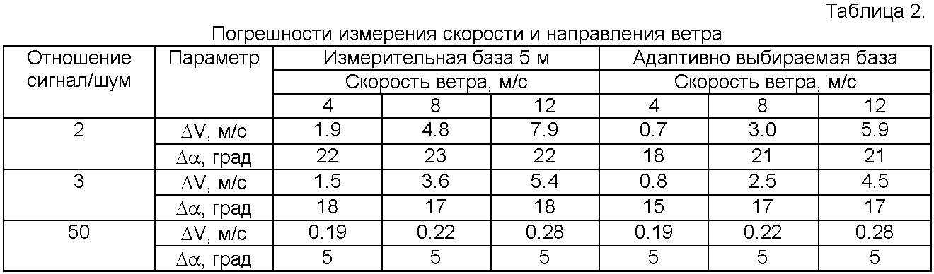
Результаты моделирования показывают, что описанный способ позволяет уменьшить погрешности ΔV измерения скорости ветра. При небольшом отношении сигнал/шум (на больших расстояниях от лидара) погрешности измерения скорости ветра могут уменьшаться в 1,5-2 раза.The simulation results show that the described method allows to reduce the error ΔV measurement of wind speed. With a small signal-to-noise ratio (at large distances from the lidar), wind speed measurement errors can decrease by 1.5–2 times.
Таким образом, описанный способ позволяет обеспечить увеличение точности оперативных дистанционных измерений скорости ветра.Thus, the described method allows to increase the accuracy of operational remote measurements of wind speed.
Источники информацииInformation sources
1. Заявка РСТ WO 2006/063463. Optical transit time velocimeter. International Publication Date 22.06.2006. International Patent Classification G01P 5/20, G01P 5/26.1. PCT Application WO 2006/063463. Optical transit time velocimeter. International Publication Date 06/22/2006. International Patent Classification G01P 5/20, G01P 5/26.
2. Патент RU 2404435. Способ оперативного дистанционного определения скорости и направления ветра. Дата действия патента 04.06.2009. МПК G01P 5/22, G01P 5/26, G01S 17/95.2. Patent RU 2404435. A method for operational remote sensing of wind speed and direction. The patent is valid on June 4, 2009. IPC G01P 5/22, G01P 5/26, G01S 17/95.
3. Armstrong R.L., Mason J.B., Barber Т. Detection of atmospheric aerosol flow using a transit-time lidar velocimeter // Applied Optics. - 1976. - V.15. - N 11. - P.2891-2895.3. Armstrong R.L., Mason J.B., Barber T. Detection of atmospheric aerosol flow using a transit-time lidar velocimeter // Applied Optics. - 1976. - V.15. - N 11. - P.2891-2895.
4. Применение корреляционных методов в атмосферной оптике / В.М.Орлов, Г.Г.Матвиенко, И.В.Самохвалов и др. - Новосибирск: Наука, 1983. - 160 с.4. The use of correlation methods in atmospheric optics / V. M. Orlov, G. G. Matvienko, I. V. Samokhvalov and others. - Novosibirsk: Nauka, 1983. - 160 p.
5. Корреляционные методы лазерно-локационных измерений скорости ветра / Г.Г.Матвиенко, Г.О.Заде, Э.С.Фердинандов и др. - Новосибирск: Наука, 1985. - 223 с.5. Correlation methods of laser-location measurements of wind speed / G. G. Matvienko, G. O. Zade, E. S. Ferdinandov et al. - Novosibirsk: Nauka, 1985. - 223 p.
6. Матвиенко Г.Г., Самохвалов И.В., B.C.Рыбалко и др. Оперативное определение компонентов скорости ветра с помощью лидара // Оптика атмосферы и океана. - 1988. - T.1. - N 2. - С.68-72.6. Matvienko GG, Samokhvalov IV, B.C. Rybalko et al. Operational determination of wind speed components using a lidar // Atmospheric and Ocean Optics. - 1988. - T.1. -
Claims (1)

Priority Applications (1)
| Application Number | Priority Date | Filing Date | Title |
|---|---|---|---|
| RU2011126903/28A RU2465606C1 (en) | 2011-06-30 | 2011-06-30 | Adaptive method for rapid remote measurement of wind speed and direction |
Applications Claiming Priority (1)
| Application Number | Priority Date | Filing Date | Title |
|---|---|---|---|
| RU2011126903/28A RU2465606C1 (en) | 2011-06-30 | 2011-06-30 | Adaptive method for rapid remote measurement of wind speed and direction |
Publications (1)
| Publication Number | Publication Date |
|---|---|
| RU2465606C1 true RU2465606C1 (en) | 2012-10-27 |
Family
ID=47147581
Family Applications (1)
| Application Number | Title | Priority Date | Filing Date |
|---|---|---|---|
| RU2011126903/28A RU2465606C1 (en) | 2011-06-30 | 2011-06-30 | Adaptive method for rapid remote measurement of wind speed and direction |
Country Status (1)
| Country | Link |
|---|---|
| RU (1) | RU2465606C1 (en) |
Cited By (3)
| Publication number | Priority date | Publication date | Assignee | Title |
|---|---|---|---|---|
| RU2600519C1 (en) * | 2015-08-26 | 2016-10-20 | Федеральное государственное бюджетное учреждение науки Институт мониторинга климатических и экологических систем Сибирского отделения Российской академии наук (ИМКЭС СО РАН) | Method for determination of averaged values of wind speed and direction |
| RU2616352C1 (en) * | 2016-03-01 | 2017-04-14 | Федеральное государственное бюджетное учреждение науки Институт мониторинга климатических и экологических систем Сибирского отделения Российской академии наук | Method for determining averaged values of horizontal and vertical wind speed components and its direction |
| RU2617020C1 (en) * | 2016-05-04 | 2017-04-19 | Федеральное государственное бюджетное учреждение науки Институт мониторинга климатических и экологических систем Сибирского отделения Российской академии наук | Method for determining averaged wind speed vector |
Citations (4)
| Publication number | Priority date | Publication date | Assignee | Title |
|---|---|---|---|---|
| RU2028007C1 (en) * | 1991-11-04 | 1995-01-27 | Малое предприятие "Межотраслевой научно-внедренческий центр "Экоприбор" | Method of location of source of ejection |
| US6535158B2 (en) * | 2000-03-15 | 2003-03-18 | Utah State University Research Foundation | Kinematic analysis of conically scanned environmental properties |
| RU2365942C1 (en) * | 2008-02-05 | 2009-08-27 | Институт оптики атмосферы им. В.Е. Зуева СО РАН | Way of determination of disseminating spatially distributed object speed and doppler low-coherent lidar for its realisation |
| RU2404435C1 (en) * | 2009-06-04 | 2010-11-20 | Государственное образовательное учреждение высшего профессионального образования "Московский государственный технический университет имени Н.Э. Баумана" (ГОУ ВПО МГТУ им. Н.Э. Баумана) | Method for real-time remote determination of wind speed and direction |
-
2011
- 2011-06-30 RU RU2011126903/28A patent/RU2465606C1/en not_active IP Right Cessation
Patent Citations (4)
| Publication number | Priority date | Publication date | Assignee | Title |
|---|---|---|---|---|
| RU2028007C1 (en) * | 1991-11-04 | 1995-01-27 | Малое предприятие "Межотраслевой научно-внедренческий центр "Экоприбор" | Method of location of source of ejection |
| US6535158B2 (en) * | 2000-03-15 | 2003-03-18 | Utah State University Research Foundation | Kinematic analysis of conically scanned environmental properties |
| RU2365942C1 (en) * | 2008-02-05 | 2009-08-27 | Институт оптики атмосферы им. В.Е. Зуева СО РАН | Way of determination of disseminating spatially distributed object speed and doppler low-coherent lidar for its realisation |
| RU2404435C1 (en) * | 2009-06-04 | 2010-11-20 | Государственное образовательное учреждение высшего профессионального образования "Московский государственный технический университет имени Н.Э. Баумана" (ГОУ ВПО МГТУ им. Н.Э. Баумана) | Method for real-time remote determination of wind speed and direction |
Cited By (3)
| Publication number | Priority date | Publication date | Assignee | Title |
|---|---|---|---|---|
| RU2600519C1 (en) * | 2015-08-26 | 2016-10-20 | Федеральное государственное бюджетное учреждение науки Институт мониторинга климатических и экологических систем Сибирского отделения Российской академии наук (ИМКЭС СО РАН) | Method for determination of averaged values of wind speed and direction |
| RU2616352C1 (en) * | 2016-03-01 | 2017-04-14 | Федеральное государственное бюджетное учреждение науки Институт мониторинга климатических и экологических систем Сибирского отделения Российской академии наук | Method for determining averaged values of horizontal and vertical wind speed components and its direction |
| RU2617020C1 (en) * | 2016-05-04 | 2017-04-19 | Федеральное государственное бюджетное учреждение науки Институт мониторинга климатических и экологических систем Сибирского отделения Российской академии наук | Method for determining averaged wind speed vector |
Similar Documents
| Publication | Publication Date | Title |
|---|---|---|
| CN109164430B (en) | System and method for detecting position and posture of target by using laser echo and light spot | |
| US10690773B2 (en) | Systems and methods for efficient multi-return light detectors | |
| US11753003B2 (en) | Surface normal determination for LIDAR range samples by detecting probe pulse stretching | |
| US7788067B2 (en) | Means and methods for signal validation for sizing spherical objects | |
| CN108089193A (en) | Laser distance measurement module with polarization analysis | |
| TWI678745B (en) | Non-destructive acoustic metrology for void detection | |
| WO2005100911A2 (en) | An apparatus and method for optical determination of intermediate distances | |
| EP2661636B1 (en) | Method and device for determining the movements of a fluid from remote measurements of radial velocities | |
| WO2017177967A1 (en) | Underwater detection system and underwater detection method | |
| CN106415313A (en) | Multi-target laser distance meter | |
| RU2465606C1 (en) | Adaptive method for rapid remote measurement of wind speed and direction | |
| CN101828929B (en) | Vector measurement method of Doppler blood flow velocity by utilizing apparent displacement | |
| US10914812B2 (en) | Method for locating sources emitting electromagnetic pulses | |
| GB2306825A (en) | Laser ranging using time correlated single photon counting | |
| RU2518009C1 (en) | Correlation method of improving velocity and range resolution for pulsed doppler systems with intrapulse coherent processing | |
| RU2404435C1 (en) | Method for real-time remote determination of wind speed and direction | |
| US20160231348A1 (en) | Laser anemometry system and method | |
| CA2774758C (en) | Method and device for measuring a profile of the ground | |
| CN111880188A (en) | Optical coherent ranging device and method | |
| RU2494422C2 (en) | Laser remote evaluation method of instantaneous speed and direction of wind | |
| US8976342B2 (en) | Method for estimating the transverse component of the velocity of the air in a doppler LiDAR measurement | |
| EP1324065B1 (en) | Method for passively finding the position of a target and especially for air-air locating | |
| RU2515419C1 (en) | Method of measuring change in course angle of probing signal source | |
| KR101179952B1 (en) | 3-demensional measureing system using a noncontact type probe simultaneously | |
| JP3235368B2 (en) | Laser Doppler velocity measuring device |
Legal Events
| Date | Code | Title | Description |
|---|---|---|---|
| MM4A | The patent is invalid due to non-payment of fees |
Effective date: 20190701 |