RU2463503C1 - Needle valve - Google Patents
Needle valve Download PDFInfo
- Publication number
- RU2463503C1 RU2463503C1 RU2011110961/06A RU2011110961A RU2463503C1 RU 2463503 C1 RU2463503 C1 RU 2463503C1 RU 2011110961/06 A RU2011110961/06 A RU 2011110961/06A RU 2011110961 A RU2011110961 A RU 2011110961A RU 2463503 C1 RU2463503 C1 RU 2463503C1
- Authority
- RU
- Russia
- Prior art keywords
- channel
- main
- drainage
- needle valve
- channels
- Prior art date
Links
- 238000009434 installation Methods 0.000 claims description 4
- 230000003993 interaction Effects 0.000 claims description 4
- 230000008707 rearrangement Effects 0.000 claims description 2
- 238000013461 design Methods 0.000 abstract description 2
- 239000000126 substance Substances 0.000 abstract 1
- 230000006866 deterioration Effects 0.000 description 3
- 238000006073 displacement reaction Methods 0.000 description 2
- 238000005259 measurement Methods 0.000 description 2
- 210000000056 organ Anatomy 0.000 description 2
- 238000011161 development Methods 0.000 description 1
- 230000013011 mating Effects 0.000 description 1
- 238000007789 sealing Methods 0.000 description 1
- 238000012360 testing method Methods 0.000 description 1
Images
Landscapes
- Measuring Fluid Pressure (AREA)
Abstract
Description
Изобретение относится к арматуростроению и может быть использовано при разработке устройств для систем перекрытия и сброса давления в коммуникациях.The invention relates to valve engineering and can be used in the development of devices for overlapping and pressure relief systems in communications.
Известен запорно-дренажный вентиль, в корпусе которого выполнены входной и дренажный каналы, соединенные ступенчатым каналом, кромкой которого образовано седло, и размещены основной и дренажный запорные органы, при этом основной запорный орган установлен с возможностью взаимодействия с седлом, образованным кромкой ступенчатого канала, а дренажный канал разветвлен крестообразно, выход каждого из разветвлений выполнен в виде конусного резьбового отверстия, при этом дренажный запорный орган размещен во втулке, установленной в одном из отверстий и выполненной с седлом, а в других отверстиях установлены заглушка и манометр с возможностью их перестановки (патент РФ №2105217, MПК F16K 1/00 - прототип).Known shut-off valve, in the body of which there is an inlet and drainage channels connected by a stepped channel, the edge of which is formed a saddle, and placed the main and drain shut-off bodies, while the main shut-off element is installed with the possibility of interaction with the saddle formed by the edge of the stepped channel, and the drainage channel is branched crosswise, the output of each of the branches is made in the form of a conical threaded hole, while the drainage locking element is placed in a sleeve installed in one of holes and made with a saddle, and in other holes a plug and a manometer are installed with the possibility of their rearrangement (RF patent No. 2105217, IPC
Указанный вентиль работает следующим образом.The specified valve operates as follows.
При наличии в системе давления и необходимости его контроля вращением маховика против часовой стрелки запорный орган отводится от седла корпуса, образуется зазор, через который система подсоединяется к манометру. После снятия показания манометра вентиль закрывается. Вращением дренажного органа во втулке против часовой стрелки открывается дренажное отверстие в седле и избыточное давление из полости манометра стравливается, после чего дренажный вентиль закрывается.If there is pressure in the system and the need to control it by rotating the flywheel counterclockwise, the shut-off element is diverted from the seat of the housing, a gap is formed through which the system is connected to the pressure gauge. After reading the pressure gauge, the valve closes. By rotating the drainage body in the sleeve counterclockwise, the drainage hole in the saddle opens and excess pressure is vented from the pressure gauge cavity, after which the drainage valve closes.
Недостатками данного вентиля являются его ограниченная применимость, низкая надежность его работы.The disadvantages of this valve are its limited applicability, low reliability of its operation.
Задачей предложенного изобретения является расширение функциональных возможностей вентиля и повышение надежности его работы.The objective of the invention is to expand the functionality of the valve and increase the reliability of its operation.
Решение поставленной задачи достигается за счет того, что в предложенном игольчатом вентиле, содержащем корпус, в котором выполнены входной и дренажный каналы, соединенные между собой ступенчатым каналом, кромкой которого образовано седло, установлены основной и дренажный запорные органы, при этом основной запорный орган установлен с возможностью взаимодействия с седлом, образованным кромкой ступенчатого канала, а дренажный канал имеет ответвления, причем выход каждого из ответвлений выполнен в виде конусного резьбового отверстия, при этом дренажный запорный орган размещен предпочтительно во втулке, установленной в одном из отверстий и выполненной с седлом, а в других отверстиях установлены с возможностью их перестановки преимущественно заглушка и предпочтительно средство для измерения давления, преимущественно манометр, согласно изобретению выходная часть входного канала выполнена состоящей, как минимум, из двух сопряженных между собой каналов, входные части которых выполнены профилированными в виде ступенчатого канала и соединены между собой, а выходные расположены преимущественно на смежных поверхностях корпуса вентиля, предпочтительно перпендикулярных, при этом, как минимум, в одной, предпочтительно в каждой, выходной части указанных каналов установлен дополнительный запорный орган, предпочтительно идентичный основному.The solution to this problem is achieved due to the fact that in the proposed needle valve containing a housing in which the inlet and drainage channels are connected, interconnected by a stepped channel, the edge of which is formed a saddle, the main and drainage shut-off bodies are installed, while the main shut-off element is installed with the possibility of interaction with the saddle formed by the edge of the stepped channel, and the drainage channel has branches, and the output of each of the branches is made in the form of a conical threaded hole, pr and this drainage locking element is preferably placed in a sleeve mounted in one of the holes and made with a saddle, and in the other holes are installed with the possibility of their displacement mainly a plug and preferably a means for measuring pressure, mainly a manometer, according to the invention, the output part of the inlet channel is made up of at least two interconnected channels, the input parts of which are profiled in the form of a stepped channel and are interconnected, and the output predominantly located on adjacent surfaces of the valve body, preferably perpendicular, with at least one, preferably in each, output part of these channels, an additional locking element, preferably identical to the main one, is installed.
В варианте исполнения продольные оси основного и, как минимум, одного дополнительного запорного органа расположены преимущественно в одной плоскости, проходящей перпендикулярно корпусу вентиля через продольную ось ступенчатого канала, что позволяет обеспечить требуемые массово-габаритные характеристики.In an embodiment, the longitudinal axes of the main and at least one additional locking element are located mainly in one plane, perpendicular to the valve body through the longitudinal axis of the stepped channel, which ensures the required mass-dimensional characteristics.
В варианте исполнения входной канал выполнен под углом к продольной оси корпуса, причем угол наклона выбирается из соотношения α=(0,8…1,2)arctgh/l, при этом h=(0,8…1,2)l, где α - угол наклона отверстия к продольной оси игольчатого вентиля, h - высота входного канала в плоскости установки основного запорного элемента, l - длина от входной плоскости корпуса игольчатого вентиля до оси канала в плоскости установки основного запорного элемента.In the embodiment, the input channel is made at an angle to the longitudinal axis of the housing, and the inclination angle is selected from the relation α = (0.8 ... 1.2) arctan h / l , while h = (0.8 ... 1.2) l, where α is the angle of inclination of the hole to the longitudinal axis of the needle valve, h is the height of the input channel in the plane of installation of the main locking element, l is the length from the input plane of the body of the needle valve to the channel axis in the plane of installation of the main locking element.
Нижнее значение указанных пределов выбрано исходя из того, что при дальнейшем их уменьшении происходит значительное увеличение поперечных размеров корпуса вентиля, что приводит к ухудшению массово-габаритных характеристик вентиля.The lower value of these limits is chosen based on the fact that with their further decrease, a significant increase in the transverse dimensions of the valve body occurs, which leads to a deterioration in the mass-dimensional characteristics of the valve.
Верхнее значение указанных пределов выбрано исходя из того, что при дальнейшем их увеличении происходит значительное увеличение поперечных размеров корпуса, что приводит к ухудшению массово-габаритных характеристик вентиля.The upper value of these limits is chosen based on the fact that with their further increase there is a significant increase in the transverse dimensions of the body, which leads to a deterioration in the mass-dimensional characteristics of the valve.
В варианте исполнения основной и запорный дренажный элементы установлены таким образом, что расстояние L между их продольными осями составляет L=(2…10)d, преимущественно L=(4…8)d, где L - расстояние между продольными осями основного и дренажного запорных элементов, d - диаметр дренажного канала.In the embodiment, the main and locking drainage elements are installed in such a way that the distance L between their longitudinal axes is L = (2 ... 10) d, mainly L = (4 ... 8) d, where L is the distance between the longitudinal axes of the main and drainage locking elements, d - diameter of the drainage channel.
Нижнее значение указанного предела выбрано исходя из того, что при дальнейшем его уменьшении происходит потеря прочностных свойств корпуса вентиля из-за чрезмерного утонения его стенок.The lower value of the specified limit is chosen based on the fact that with a further decrease in it, the strength properties of the valve body are lost due to excessive thinning of its walls.
Верхнее значение указанного предела выбрано исходя из того, что при дальнейшем их увеличении происходит значительное увеличение длины корпуса вентиля, что приводит к ухудшению массово-габаритных характеристик вентиля.The upper value of the specified limit is selected based on the fact that with their further increase there is a significant increase in the length of the valve body, which leads to a deterioration in the mass-dimensional characteristics of the valve.
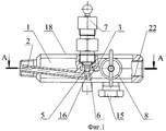
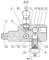
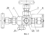
Сущность изобретения иллюстрируется чертежами, где на фиг.1 показан продольный разрез предложенного игольчатого вентиля, на фиг.2 - поперечный разрез по продольной оси предложенного игольчатого вентиля, на фиг.3 - вид спереди.The invention is illustrated by drawings, where figure 1 shows a longitudinal section of the proposed needle valve, figure 2 is a transverse section along the longitudinal axis of the proposed needle valve, figure 3 is a front view.
Игольчатый вентиль содержит корпус 1, в котором выполнены входной 2 и дренажный 3 каналы, соединенные между собой ступенчатым каналом 4. Кромка 5 указанного канала 4 образует седло 6. В корпусе 1 установлены основной 7 и дренажный 8 запорные органы. Основной запорный орган 7 установлен с возможностью взаимодействия с седлом 6, образованным кромкой ступенчатого канала 4. Дренажный канал 3 имеет ответвления 10, 11, 12, причем выход каждого из ответвлений выполнен в виде конусного резьбового отверстия. Дренажный запорный орган 8 размещен во втулке 13, установленной в одном из отверстий и выполненной с седлом 14. В других отверстиях установлены с возможностью их перестановки заглушка 15 и предпочтительно средство для измерения давления, преимущественно, манометр (не показан). Выходная часть входного канала 2 выполнена состоящей из двух сопряженных между собой каналов 16 и 17, входные части которых выполнены профилированными в виде ступенчатого канала 4. Выходные части каналов 16 и 17 расположены на смежных поверхностях 18 и 19 корпуса 1 вентиля. В выходной части одного из указанных каналов установлен дополнительный запорный орган 20, предпочтительно идентичный основному запорному органу 7.The needle valve comprises a
Корпус 1 клапана со стороны входа имеет наружную коническую резьбу 21, при помощи которой подсоединяется к ответной резьбе оборудования, а со стороны выхода - внутреннюю коническую резьбу 22 на ответвлениях 10, 11 и 12.The
Предложенное устройство работает следующим образом.The proposed device operates as follows.
Корпус 1 клапана при помощи наружной конической резьбы 21 подсоединяется к ответной резьбе оборудования, во внутренней системе которого необходимо измерить давление. Во внутреннюю коническую резьбу 22 на ответвлении 12 устанавливается манометр для измерения давления (условно не показан). Манометр может устанавливаться в гнездо заглушки 15. В этом случае заглушка 15 устанавливается в выходное отверстие ответвления 10 или 11. Вентиль устанавливается на оборудование при закрытом положении основного 7 запорного органа и открытом положении дополнительного запорного органа 20 и дренажного 8 запорного органа.The
При использовании основного 7 запорного органа дополнительный запорный орган 20 всегда находится в открытом положении. Перед подачей давления рабочей среды из системы на манометр дренажный 8 запорный орган закрывается. Затем открывается основной 7 запорный орган, образуя зазор между седлом 6 и исполнительным механизмом вентиля, через который давление подается на манометр.When using the main 7 locking element
По окончании замеров основной 7 запорный орган закрывается и открывается дренажный 8 запорный орган. Давление сбрасывается через дренажное отверстие в штуцере.At the end of the measurements, the main 7 locking organ closes and the
При использовании дополнительного запорного органа 20 основной 7 запорный орган всегда находится в открытом положении. Перед подачей давления рабочей среды из системы на манометр дренажный 8 запорный орган закрывается. Затем открывается дополнительный 20 запорный орган, образуя зазор между седлом 6 и исполнительным механизмом вентиля, через который давление подается на манометр.When using an
По окончании замеров дополнительный 20 запорный орган закрывается и открывается дренажный 8 запорный орган. Давление сбрасывается через дренажное отверстие в штуцере.At the end of the measurements, an additional 20 locking member closes and the
При обнаружении утечек по исполнительному механизму основного запорного 7 органа для дополнительной герметизации используется дополнительный 20 запорный орган.If leaks are detected by the actuator of the
Проведенные авторами и заявителем испытания предложенного полноразмерного игольчатого вентиля подтвердили правильность заложенных конструкторско-технологических решений и выбранных пределов.The tests performed by the authors and the applicant of the proposed full-sized needle valve confirmed the correctness of the design and technological solutions and the selected limits.
Использование предложенного технического решения позволит расширить функциональные возможности вентиля и повысить надежность его работы за счет дублирования основных элементов.Using the proposed technical solution will expand the functionality of the valve and increase the reliability of its operation due to duplication of the main elements.
Claims (4)
Priority Applications (1)
| Application Number | Priority Date | Filing Date | Title |
|---|---|---|---|
| RU2011110961/06A RU2463503C1 (en) | 2011-03-24 | 2011-03-24 | Needle valve |
Applications Claiming Priority (1)
| Application Number | Priority Date | Filing Date | Title |
|---|---|---|---|
| RU2011110961/06A RU2463503C1 (en) | 2011-03-24 | 2011-03-24 | Needle valve |
Publications (1)
| Publication Number | Publication Date |
|---|---|
| RU2463503C1 true RU2463503C1 (en) | 2012-10-10 |
Family
ID=47079605
Family Applications (1)
| Application Number | Title | Priority Date | Filing Date |
|---|---|---|---|
| RU2011110961/06A RU2463503C1 (en) | 2011-03-24 | 2011-03-24 | Needle valve |
Country Status (1)
| Country | Link |
|---|---|
| RU (1) | RU2463503C1 (en) |
Cited By (1)
| Publication number | Priority date | Publication date | Assignee | Title |
|---|---|---|---|---|
| RU2746011C2 (en) * | 2017-03-01 | 2021-04-05 | Роузмаунт Инк. | Valve system |
Citations (5)
| Publication number | Priority date | Publication date | Assignee | Title |
|---|---|---|---|---|
| GB791945A (en) * | 1954-12-17 | 1958-03-12 | Avery Ltd W & T | An improved needle valve |
| SU1328629A1 (en) * | 1985-10-23 | 1987-08-07 | Всесоюзный научно-исследовательский институт сахарной промышленности | Gate for pipelines |
| CA2102877A1 (en) * | 1992-11-12 | 1994-05-13 | Todd R. Feld | Fluid flow regulating valve |
| RU2105217C1 (en) * | 1995-04-14 | 1998-02-20 | Воронежский механический завод | Shut-off drain valve |
| RU101761U1 (en) * | 2010-09-20 | 2011-01-27 | Федеральное государственное унитарное предприятие "Завод "Прибор" | VALVE VALVE VALVE FOR REGULATING THE WORKING FLOW |
-
2011
- 2011-03-24 RU RU2011110961/06A patent/RU2463503C1/en not_active IP Right Cessation
Patent Citations (5)
| Publication number | Priority date | Publication date | Assignee | Title |
|---|---|---|---|---|
| GB791945A (en) * | 1954-12-17 | 1958-03-12 | Avery Ltd W & T | An improved needle valve |
| SU1328629A1 (en) * | 1985-10-23 | 1987-08-07 | Всесоюзный научно-исследовательский институт сахарной промышленности | Gate for pipelines |
| CA2102877A1 (en) * | 1992-11-12 | 1994-05-13 | Todd R. Feld | Fluid flow regulating valve |
| RU2105217C1 (en) * | 1995-04-14 | 1998-02-20 | Воронежский механический завод | Shut-off drain valve |
| RU101761U1 (en) * | 2010-09-20 | 2011-01-27 | Федеральное государственное унитарное предприятие "Завод "Прибор" | VALVE VALVE VALVE FOR REGULATING THE WORKING FLOW |
Cited By (1)
| Publication number | Priority date | Publication date | Assignee | Title |
|---|---|---|---|---|
| RU2746011C2 (en) * | 2017-03-01 | 2021-04-05 | Роузмаунт Инк. | Valve system |
Similar Documents
| Publication | Publication Date | Title |
|---|---|---|
| US20210123842A1 (en) | Shear box of shear rheology experiment of a soft rock for simulating the coupling of the rainfall seepage and blasting vibration | |
| CN101398355B (en) | Three-axis infiltration experiment device | |
| ES2681228T3 (en) | Oil hydraulic valve | |
| US20090236847A1 (en) | Pipe insert | |
| CN104729969B (en) | Surrouding rock stress level of disruption test device | |
| RU2463503C1 (en) | Needle valve | |
| CN106595991A (en) | Hydraulic test device of prefabricated pipe rack joint and using method thereof | |
| JP6779447B2 (en) | Piping test jig in water supply extraction construction | |
| RU2463504C1 (en) | Application of needle valve | |
| AU2005218073B2 (en) | Pipe insert | |
| DE102007025474B4 (en) | load cell | |
| CA3037864C (en) | Quick test sub coiled tubing connector | |
| CN107764654B (en) | Multi-test-block seepage test device and use method | |
| KR101821890B1 (en) | Fracture toughness test apparatus | |
| KR101418370B1 (en) | A Test Block Apparatus For Solenoid Valve And A Test Method Using Of It | |
| CN204000823U (en) | A kind of earth pressure gauge ejects erector | |
| KR102901685B1 (en) | A tensile test device using fluid pressure for whole pipe or pipe/joint assemblies | |
| RU2105217C1 (en) | Shut-off drain valve | |
| CN209294625U (en) | A kind of instrument three-way connection with damping hole | |
| CN207749118U (en) | A kind of split type clasmatosis structure | |
| DE102012223889B4 (en) | Arrangement for pneumatic or hydraulic pressure measurement | |
| CN107255547B (en) | Dynamic pore water pressure gauge verification pressure cavity device and verification method | |
| CN115824480B (en) | Quantitative oiling device of borehole stressmeter | |
| CN204241060U (en) | Fuel manifold flow rate test joint | |
| RU2473061C1 (en) | Shutoff separating device for pressure gauges |
Legal Events
| Date | Code | Title | Description |
|---|---|---|---|
| MM4A | The patent is invalid due to non-payment of fees |
Effective date: 20130325 |