RU2461730C2 - Diagnostic of contamination state of plugs of radio frequency ignition system - Google Patents
Diagnostic of contamination state of plugs of radio frequency ignition system Download PDFInfo
- Publication number
- RU2461730C2 RU2461730C2 RU2010100824/07A RU2010100824A RU2461730C2 RU 2461730 C2 RU2461730 C2 RU 2461730C2 RU 2010100824/07 A RU2010100824/07 A RU 2010100824/07A RU 2010100824 A RU2010100824 A RU 2010100824A RU 2461730 C2 RU2461730 C2 RU 2461730C2
- Authority
- RU
- Russia
- Prior art keywords
- ignition
- resonator
- electrodes
- voltage
- power circuit
- Prior art date
Links
Images
Classifications
-
- F—MECHANICAL ENGINEERING; LIGHTING; HEATING; WEAPONS; BLASTING
- F02—COMBUSTION ENGINES; HOT-GAS OR COMBUSTION-PRODUCT ENGINE PLANTS
- F02P—IGNITION, OTHER THAN COMPRESSION IGNITION, FOR INTERNAL-COMBUSTION ENGINES; TESTING OF IGNITION TIMING IN COMPRESSION-IGNITION ENGINES
- F02P9/00—Electric spark ignition control, not otherwise provided for
- F02P9/002—Control of spark intensity, intensifying, lengthening, suppression
- F02P9/007—Control of spark intensity, intensifying, lengthening, suppression by supplementary electrical discharge in the pre-ionised electrode interspace of the sparking plug, e.g. plasma jet ignition
-
- F—MECHANICAL ENGINEERING; LIGHTING; HEATING; WEAPONS; BLASTING
- F02—COMBUSTION ENGINES; HOT-GAS OR COMBUSTION-PRODUCT ENGINE PLANTS
- F02P—IGNITION, OTHER THAN COMPRESSION IGNITION, FOR INTERNAL-COMBUSTION ENGINES; TESTING OF IGNITION TIMING IN COMPRESSION-IGNITION ENGINES
- F02P17/00—Testing of ignition installations, e.g. in combination with adjusting; Testing of ignition timing in compression-ignition engines
- F02P17/12—Testing characteristics of the spark, ignition voltage or current
-
- F—MECHANICAL ENGINEERING; LIGHTING; HEATING; WEAPONS; BLASTING
- F02—COMBUSTION ENGINES; HOT-GAS OR COMBUSTION-PRODUCT ENGINE PLANTS
- F02P—IGNITION, OTHER THAN COMPRESSION IGNITION, FOR INTERNAL-COMBUSTION ENGINES; TESTING OF IGNITION TIMING IN COMPRESSION-IGNITION ENGINES
- F02P23/00—Other ignition
- F02P23/04—Other physical ignition means, e.g. using laser rays
-
- H—ELECTRICITY
- H01—ELECTRIC ELEMENTS
- H01T—SPARK GAPS; OVERVOLTAGE ARRESTERS USING SPARK GAPS; SPARKING PLUGS; CORONA DEVICES; GENERATING IONS TO BE INTRODUCED INTO NON-ENCLOSED GASES
- H01T13/00—Sparking plugs
- H01T13/58—Testing
-
- H—ELECTRICITY
- H01—ELECTRIC ELEMENTS
- H01T—SPARK GAPS; OVERVOLTAGE ARRESTERS USING SPARK GAPS; SPARKING PLUGS; CORONA DEVICES; GENERATING IONS TO BE INTRODUCED INTO NON-ENCLOSED GASES
- H01T13/00—Sparking plugs
- H01T13/58—Testing
- H01T13/60—Testing of electrical properties
-
- F—MECHANICAL ENGINEERING; LIGHTING; HEATING; WEAPONS; BLASTING
- F02—COMBUSTION ENGINES; HOT-GAS OR COMBUSTION-PRODUCT ENGINE PLANTS
- F02D—CONTROLLING COMBUSTION ENGINES
- F02D41/00—Electrical control of supply of combustible mixture or its constituents
- F02D41/02—Circuit arrangements for generating control signals
- F02D41/021—Introducing corrections for particular conditions exterior to the engine
- F02D41/0235—Introducing corrections for particular conditions exterior to the engine in relation with the state of the exhaust gas treating apparatus
- F02D41/027—Introducing corrections for particular conditions exterior to the engine in relation with the state of the exhaust gas treating apparatus to purge or regenerate the exhaust gas treating apparatus
- F02D41/029—Introducing corrections for particular conditions exterior to the engine in relation with the state of the exhaust gas treating apparatus to purge or regenerate the exhaust gas treating apparatus the exhaust gas treating apparatus being a particulate filter
-
- F—MECHANICAL ENGINEERING; LIGHTING; HEATING; WEAPONS; BLASTING
- F02—COMBUSTION ENGINES; HOT-GAS OR COMBUSTION-PRODUCT ENGINE PLANTS
- F02P—IGNITION, OTHER THAN COMPRESSION IGNITION, FOR INTERNAL-COMBUSTION ENGINES; TESTING OF IGNITION TIMING IN COMPRESSION-IGNITION ENGINES
- F02P17/00—Testing of ignition installations, e.g. in combination with adjusting; Testing of ignition timing in compression-ignition engines
- F02P17/12—Testing characteristics of the spark, ignition voltage or current
- F02P2017/121—Testing characteristics of the spark, ignition voltage or current by measuring spark voltage
-
- G—PHYSICS
- G01—MEASURING; TESTING
- G01R—MEASURING ELECTRIC VARIABLES; MEASURING MAGNETIC VARIABLES
- G01R31/00—Arrangements for testing electric properties; Arrangements for locating electric faults; Arrangements for electrical testing characterised by what is being tested not provided for elsewhere
- G01R31/005—Testing of electric installations on transport means
- G01R31/006—Testing of electric installations on transport means on road vehicles, e.g. automobiles or trucks
Abstract
Description
Настоящее изобретение в целом относится к системам генерирования плазмы между двумя электродами свечи, используемой, в частности, для управляемого радиочастотного воспламенения газовой смеси в камерах сгорания двигателя внутреннего сгорания.The present invention generally relates to plasma generation systems between two electrodes of a candle, used in particular for controlled radio frequency ignition of a gas mixture in a combustion chamber of an internal combustion engine.
В частности, объектом настоящего изобретения является устройство радиочастотного зажигания, содержащее:In particular, an object of the present invention is a radio frequency ignition device, comprising:
- средства управления, выполненные с возможностью генерирования сигнала управления зажиганием,- controls configured to generate an ignition control signal,
- цепь питания, управляемую сигналом управления зажиганием, для подачи напряжения питания на выходной интерфейс цепи питания на частоте, определяемой сигналом управления,- a power circuit controlled by the ignition control signal for supplying voltage to the output interface of the power circuit at a frequency determined by the control signal,
- по меньшей мере, один резонатор генерирования плазмы, соединенный с выходным интерфейсом цепи питания и выполненный с возможностью генерирования искры между двумя электродами указанного резонатора по время подачи команды на зажигание.- at least one plasma generation resonator connected to the output interface of the power circuit and configured to generate a spark between the two electrodes of the specified resonator during the ignition command.
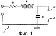
В варианте применения для автомобильного зажигания с генерированием плазмы используют катушки-свечи (подробно описанные в следующих патентных заявках, поданных на имя заявителя: FR 03-10766, FR 03-10767 и FR 03-10768), моделируемые в виде резонатора 1 (см. фиг.1), резонансная частота Fc которого превышает 1 МГц и обычно близка к 5 МГц. Резонатор содержит последовательно соединенные резистор R, катушку индуктивности L и конденсатор С. Электроды 10 и 12 зажигания катушки-свечи соединены с контактами конденсатора С резонатора, обеспечивая генерирование многошнуровых разрядов для инициирования воспламенения смеси в камере сгорания двигателя, когда на резонатор подают питание.In an application for plasma ignition automotive ignition, candle coils are used (described in detail in the following patent applications filed in the applicant's name: FR 03-10766, FR 03-10767 and FR 03-10768), modeled as resonator 1 (see figure 1), the resonant frequency F c which exceeds 1 MHz and is usually close to 5 MHz. The resonator contains a series-connected resistor R, an inductor L and a capacitor C. The
Действительно, когда на резонатор подают высокое напряжение на его резонансной частоте Fc (l/2п![]()
![]()
В этом случае говорят о разветвленных разрядах, поскольку они предполагают одновременное генерирование, по меньшей мере, нескольких линий или путей ионизации в данном объеме, кроме того, их разветвление является многонаправленным.In this case, they speak of branched discharges, since they involve the simultaneous generation of at least several lines or ionization paths in a given volume, in addition, their branching is multidirectional.
Этот вариант применения для радиочастотного зажигания требует использования цепи питания, которая может генерировать импульсы напряжения, как правило, порядка 100 нс, которые могут достигать амплитуд порядка 1 кВ на частоте, очень близкой к резонансной частоте резонатора генерирования плазмы радиочастотной катушки-свечи. Чем меньше разность между резонансной частотой резонатора и рабочей частотой источника, тем выше коэффициент усиления напряжения резонатора (соотношение между амплитудой его выходного напряжения и его входным напряжением).This application for radio frequency ignition requires the use of a power circuit that can generate voltage pulses, typically of the order of 100 ns, which can reach amplitudes of the order of 1 kV at a frequency very close to the resonant frequency of the plasma resonator of the generation of a radio frequency candle coil. The smaller the difference between the resonant frequency of the resonator and the operating frequency of the source, the higher the gain of the resonator voltage (the ratio between the amplitude of its output voltage and its input voltage).
Такая цепь питания, подробно описанная в патентной заявке FR 03-10767, схематично показана на фиг.2. В этой цепи питания классически применяют монтажную схему, называемую «усилителем мощности класса Е». Этот тип преобразователя постоянного напряжения в переменное позволяет создавать импульсы напряжения с вышеуказанными характеристиками.Such a power circuit, described in detail in patent application FR 03-10767, is schematically shown in FIG. In this power circuit, a wiring diagram called a “Class E power amplifier” is classically used. This type of DC-AC converter allows you to create voltage pulses with the above characteristics.
Согласно варианту выполнения, показанному на фиг.2, такая цепь питания 2 содержит силовой полевой МОП-транзистор М и параллельную резонансную схему 4, содержащую катушку индуктивности Lp, параллельно соединенную с конденсатором Ср. Транзистор М используют в качестве выключателя для управления коммутациями на контактах параллельной резонансной схемы и резонатора 1 генерирования плазмы, предназначенного для подключения к выходному интерфейсу OUT цепи питания.According to the embodiment shown in FIG. 2, such a supply circuit 2 comprises a MOSFET M and a parallel resonant circuit 4 comprising an inductor Lp connected in parallel with capacitor Cp. The transistor M is used as a switch to control switching on the contacts of the parallel resonant circuit and the
Средства 5 управления цепью питания выполнены с возможностью генерирования логического сигнала V1 управления, предназначенного для подачи на затвор транзистора М на частоте, которая должна быть, по существу, отрегулирована по резонансной частоте резонатора 1.Means 5 control the power circuit is configured to generate a logical control signal V1 designed to supply the gate of the transistor M at a frequency that should be essentially adjusted to the resonant frequency of the
Описанное выше устройство зажигания питается напряжением Vinter, присутствующим на контактах конденсатора Cb цепи питания. Предпочтительно напряжение Vinter поступает от источника высокого напряжения, соединенного с конденсатором Cb и обычно являющегося преобразователем постоянного напряжения в постоянное.The ignition device described above is powered by the voltage Vinter present on the contacts of the capacitor Cb of the power circuit. Preferably, the voltage Vinter comes from a high voltage source connected to the capacitor Cb, and is usually a DC to DC converter.
Таким образом, в пределах своей резонансной частоты параллельный резонатор 4 преобразует постоянное напряжение питания Vinter в усиленное периодическое напряжение Va, соответствующее напряжению питания, умноженному на коэффициент усиления напряжения параллельного резонатора, и подаваемое на выходной интерфейс цепи питания на уровне стока транзистора-выключателя М.Thus, within its resonant frequency, the parallel resonator 4 converts the constant supply voltage Vinter into an amplified periodic voltage Va corresponding to the supply voltage multiplied by the voltage gain of the parallel resonator and supplied to the output interface of the power circuit at the drain level of the transistor-switch M.
Выключатель М подает усиленное напряжение питания Va на выход цепи питания на частоте, определяемой сигналом V1 управления, которую необходимо максимально приблизить к резонансной частоте катушки-свечи. Действительно, во время подачи команды на зажигание, чтобы получить резонанс устройства радиочастотного зажигания и обеспечить максимальное напряжение на контактах электродов катушки-свечи для получения ожидаемой искры, управление катушкой-свечой необходимо осуществлять, по существу, на ее резонансной частоте.The switch M supplies the amplified supply voltage Va to the output of the supply circuit at a frequency determined by the control signal V1, which must be brought as close as possible to the resonant frequency of the candle coil. Indeed, during the ignition command, in order to obtain the resonance of the radio frequency ignition device and to ensure maximum voltage at the electrode contacts of the candle-coil to obtain the expected spark, the control of the candle-coil must be carried out essentially at its resonant frequency.
В контексте управляемого зажигания в цилиндре двигателя внутреннего сгорания катушку-свечу завинчивают на двигателе, и ее центральный электрод располагают в камере сгорания соответствующего цилиндра двигателя. Однако, по мере появления плазменных разрядов, генерируемых катушкой-свечой, может происходить явление загрязнения свечи, которое характеризуется осаждением продуктов сгорания в виде сажи на центральном электроде и на керамике вокруг этой свечи. При превышении определенного уровня загрязнения это явление мешает нормальной работе катушки-свечи и приводит к перебоям зажигания.In the context of controlled ignition in the cylinder of an internal combustion engine, the candle coil is screwed onto the engine, and its central electrode is placed in the combustion chamber of the corresponding engine cylinder. However, as the plasma discharges generated by the coil-candle appear, the phenomenon of candle contamination can occur, which is characterized by the deposition of combustion products in the form of soot on the central electrode and on the ceramics around this candle. If a certain level of pollution is exceeded, this phenomenon interferes with the normal operation of the spark plug coil and leads to interruptions in the ignition.
До сих пор наиболее распространенным способом диагностики загрязнения электродов катушки-свечи было ее извлечение из гнезда камеры сгорания и определение состояния ее загрязнения при помощи визуального анализа.Until now, the most common way to diagnose contamination of the electrodes of a coil-candle was to remove it from the nest of the combustion chamber and determine the state of its contamination using visual analysis.
Задачей настоящего изобретения является усовершенствование диагностики состояния загрязнения электродов радиочастотной катушки-свечи.The objective of the present invention is to improve the diagnosis of contamination of the electrodes of the radio-frequency coil-candles.
Устройство в соответствии с настоящим изобретением, отвечающее определению, приведенному во вступительной части описания, в основном характеризуется тем, что содержит:The device in accordance with the present invention, which meets the definition given in the introductory part of the description, is mainly characterized in that it contains:
- средства измерения электрического параметра, характеризующего изменение напряжения питания резонатора, и- means for measuring an electrical parameter characterizing the change in the supply voltage of the resonator, and
- модуль определения состояния загрязнения электродов в зависимости от измеренного электрического параметра и заранее определенного контрольного значения.- a module for determining the state of contamination of the electrodes, depending on the measured electrical parameter and a predetermined reference value.
Предпочтительно электрическим параметром является напряжение на контактах конденсатора цепи питания, выполненного с возможностью зарядки от напряжения питания до подачи-команды на зажигание.Preferably, the electrical parameter is the voltage across the contacts of the capacitor of the power circuit, configured to charge from the supply voltage to the ignition command.
Согласно варианту выполнения, цепь питания содержит выключатель, управляемый сигналом управления зажиганием, для подачи напряжения питания на выходной интерфейс на частоте, определяемой управляющим сигналом.According to an embodiment, the power circuit comprises a switch controlled by the ignition control signal for supplying a supply voltage to the output interface at a frequency determined by the control signal.
Предпочтительно управляющая частота, по существу, равна резонансной частоте резонатора генерирования плазмы.Preferably, the control frequency is substantially equal to the resonant frequency of the plasma generating resonator.
Используемый резонатор генерирования плазмы выполнен с возможностью реализации зажигания в следующих вариантах применения: управляемое зажигание двигателя внутреннего сгорания, зажигание в фильтре-улавливателе частиц, зажигание включения очистки в системе кондиционирования воздуха.The used plasma generation resonator is configured to realize ignition in the following applications: controlled ignition of an internal combustion engine, ignition in a particle filter-catcher, ignition for turning on the cleaning in an air conditioning system.
Предпочтительно устройство в соответствии с настоящим изобретением содержит средство выдачи информации о состоянии загрязнения электродов, установленное на уровне интерфейса «человек-машина» автомобиля.Preferably, the device in accordance with the present invention includes means for providing information about the state of contamination of the electrodes, installed at the level of the human-machine interface of the car.
Объектом настоящего изобретения является также способ диагностики состояния загрязнения электродов зажигания, по меньшей мере, одного резонатора радиочастотного генерирования плазмы, подключенного к выходному интерфейсу цепи питания, конфигурированной для подачи на указанный выходной интерфейс напряжения питания на управляемой частоте во время подачи команды на зажигание, при этом указанный резонатор выполнен с возможностью генерирования искры между двумя электродами во время подачи команды на зажигание, при этом указанный способ отличается тем, что содержит следующие этапы:The object of the present invention is also a method for diagnosing a state of contamination of the ignition electrodes of at least one cavity of a radio frequency generating plasma connected to an output interface of a power circuit configured to supply a voltage at a controlled frequency to said output interface during a ignition command, wherein the specified resonator is configured to generate a spark between the two electrodes during the ignition command, the method characterized in that it contains the following steps:
- во время подачи команды на зажигание измеряют изменение электрического параметра, характеризующего изменение напряжения питания,- during the filing of the ignition command, the change in the electrical parameter characterizing the change in the supply voltage is measured,
- измеренное изменение сравнивают с заранее определенным контрольным значением;- the measured change is compared with a predetermined control value;
- состояние загрязнения электродов определяют в зависимости от разности между измеренным изменением и контрольным значением.- the state of contamination of the electrodes is determined depending on the difference between the measured change and the control value.
Предпочтительно измеряют изменение напряжения на контактах конденсатора цепи питания, при этом указанный конденсатор заряжается при подаче напряжения питания перед подачей команды на зажигание.Preferably, the voltage change across the contacts of the capacitor of the power circuit is measured, wherein said capacitor is charged when the supply voltage is applied before the ignition command is issued.
Согласно варианту выполнения, измеренное изменение вытекает из разности между измерением напряжения на контактах конденсатора в начале и в конце подачи команды на зажигание.According to an embodiment, the measured change results from the difference between the voltage measurement at the capacitor contacts at the beginning and at the end of the ignition command.
Предпочтительно контрольное значение соответствует указанному изменению до загрязнения.Preferably, the control value corresponds to the indicated change before contamination.
Предпочтительно способ содержит этап, на котором пользователь получает информацию о состоянии загрязнения. Предпочтительно такая информация, получаемая пользователем, предупреждает его о возможной скорой неисправности зажигания.Preferably, the method comprises the step of acquiring information about a state of contamination. Preferably, such information received by the user warns him of a possible imminent ignition malfunction.
Другие признаки и преимущества настоящего изобретения будут более очевидны из нижеследующего описания, представленного в качестве иллюстративного и неограничительного примера, со ссылками на прилагаемые чертежи, на которых:Other features and advantages of the present invention will be more apparent from the following description, presented by way of illustrative and non-limiting example, with reference to the accompanying drawings, in which:
фиг.1 - схема резонатора, моделирующего радиочастотную катушку-свечу генерирования плазмы;figure 1 is a diagram of a resonator simulating a radio-frequency coil-candle plasma generation;
фиг.2 - схема цепи питания, используемой для управления резонатором катушки-свечи, показанным на фиг.1;figure 2 - diagram of the power circuit used to control the resonator coil of the candle shown in figure 1;
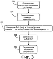
фиг.3 - блок-схема, иллюстрирующая пример осуществления способа диагностики состояния загрязнения электродов катушки-свечи;figure 3 is a flowchart illustrating an example implementation of a method for diagnosing a state of contamination of electrodes of a coil of a candle;
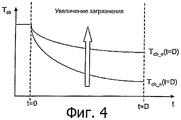
фиг.4 - схема, иллюстрирующая влияние загрязнения электродов зажигания на изменение напряжения на контактах конденсатора Сb цепи питания во время подачи команды на зажигание.4 is a diagram illustrating the effect of contamination of the ignition electrodes on the voltage change at the contacts of the capacitor Cb of the power circuit during the ignition command.
Устройство зажигания в соответствии с настоящим изобретением содержит средства 6 измерения электрического параметра, характеризующего изменение напряжения питания резонатора генерирования плазмы во время подачи команды на зажигание, и модуль 7, выполненный с возможностью определения состояния загрязнения электродов зажигания в зависимости от измеренного электрического параметра и заранее определенного контрольного значения.The ignition device in accordance with the present invention comprises means 6 for measuring an electrical parameter characterizing a change in the supply voltage of the plasma generating resonator during the ignition command, and a module 7 configured to determine the state of contamination of the ignition electrodes depending on the measured electrical parameter and a predetermined reference values.
Рассматриваемым электрическим параметром является, например, напряжение Тcb на контактах конденсатора Сb цепи питания, измеренное, по меньшей мере, в два определенных момента подачи команды на зажигание.The considered electrical parameter is, for example, the voltage T cb at the contacts of the capacitor Cb of the power circuit, measured at least at two specific times when the ignition command was issued.
Таким образом, в два определенных момента подачи команды на зажигание, выбранных, например, в начале или в конце или сразу после подачи команды на зажигание, производят измерение перепада напряжения на контактах Сb, например, используя вольтметр 6, измеряющий напряжение Тсb. Модуль 7, который может быть, например, интегрирован в средства 5 управления, снимает это электрическое измерение через приемный интерфейс 51 и определяет состояние загрязнения электродов зажигания в зависимости от этого электрического измерения изменения напряжения и от заранее определенного контрольного значения, что будет более подробно пояснено ниже.Thus, at two specific moments when the ignition command is given, selected, for example, at the beginning or at the end or immediately after the ignition command is given, the voltage drop across the contacts Cb is measured, for example, using a voltmeter 6 measuring the voltage T cb . A module 7, which can, for example, be integrated into the control means 5, takes this electrical measurement through the receiving interface 51 and determines the state of contamination of the ignition electrodes depending on this electrical measurement of the voltage change and on a predetermined reference value, which will be explained in more detail below .
Выбор измерения напряжения на контактах конденсатора Сb в определенный момент подачи команды на зажигание для диагностики состояния загрязнения электродов зажигания вытекает из следующих расчетов:The choice of measuring the voltage at the contacts of the capacitor Сb at a certain moment when the ignition command is issued to diagnose the state of contamination of the ignition electrodes follows from the following calculations:
Tcb(t) является напряжением на контактах конденсатора Сb в зависимости от времени;T cb (t) is the voltage across the terminals of the capacitor Cb versus time;
Vm(t) является напряжением на контактах конденсатора С в зависимости от времени.V m (t) is the voltage across the contacts of capacitor C as a function of time.
В момент t=0 на управляющий затвор выключателя М подается управляющий сигнал V1, что позволяет подать высокое напряжение на контакты резонатора катушки-свечи на частоте, определяемой управляющим сигналом V1.At the time t = 0, the control signal V1 is supplied to the control gate of the switch M, which makes it possible to apply a high voltage to the contacts of the resonator coil of the candle at a frequency determined by the control signal V1.
В момент t=D, следующий за подачей сигнала управления зажиганием в течение периода времени D, между электродами 10 и 12 зажигания появляется искра.At time t = D, following the supply of the ignition control signal for a period of time D, a spark appears between the
Энергетический баланс катушки-свечи показывает:The energy balance of the candle coil shows:
![]()
![]()

При этом:Wherein:
Tcb_n(t) - напряжение на контактах конденсатора Сb в зависимости от времени во время подачи команды на зажигание, когда катушка-свеча является новой, то есть до загрязнения электродов зажигания;T cb_n (t) is the voltage across the contacts of the capacitor Cb depending on the time during the ignition command when the spark plug is new, that is, before the ignition electrodes become dirty;
Tcb_e(t) - напряжение на контактах конденсатора Сb в зависимости от времени во время подачи команды на зажигание, когда электроды зажигания катушки-свечи загрязнены;T cb_e (t) is the voltage across the contacts of the capacitor Cb depending on the time during the ignition command when the ignition electrodes of the candle coil are dirty;
Vm_n(t) - напряжение на контактах конденсатора С резонатора в зависимости от времени во время подачи команды на зажигание, когда катушка-свеча является новой, то есть до загрязнения электродов зажигания;V m_n (t) is the voltage across the contacts of the resonator capacitor C, depending on the time during the ignition command when the spark plug is new, that is, before the ignition electrodes become dirty;
Vm_e(t) - напряжение на контактах конденсатора С резонатора в зависимости от времени во время подачи команды на зажигание, когда электроды зажигания катушки-свечи загрязнены, и из предыдущего уравнения следует:V m_e (t) is the voltage across the contacts of the resonator capacitor C, depending on the time during the ignition command, when the ignition electrodes of the coil-plug are dirty, and from the previous equation it follows:
![]()
![]()
иand
![]()
![]()
Следовательно, при Vm_e(t)<Vm_n(t) можно вывести следующее уравнение диагностики состояния загрязнения электродов зажигания для Tcb_n(t=0)=Tcb_e(t=0):Therefore, with V m_e (t) <V m_n (t), the following equation for diagnosing the state of contamination of the ignition electrodes can be derived for T cb_n (t = 0) = T cb_e (t = 0):
Тсb_е(t=D)>Тсb_n(t=D)T cb_e (t = D)> T cb_n (t = D)
Иначе говоря, как показано на фиг.4, перепад напряжения на контактах конденсатора СЬ во время подачи команды на зажигание (характеризующееся разностью между значением напряжения на контактах Сb, измеренном в момент t=D, и значением этого напряжения, измеренным в момент t=0) будет тем меньше, чем больше загрязнены электроды зажигания.In other words, as shown in Fig. 4, the voltage drop across the contacts of the capacitor Cb during the ignition command (characterized by the difference between the voltage value at the contacts Cb measured at time t = D and the value of this voltage measured at time t = 0 ) will be the smaller, the more dirty the ignition electrodes.
Энергетический баланс, показанный выше, можно получить для управляемой частоты, по существу, равной резонансной частоте резонатора. Действительно, поскольку перепад напряжения на контактах конденсатора Сb при подаче команды на зажигание является максимальным, когда резонатор радиочастотной катушки-свечи управляется на своей резонансной частоте, измерение напряжения, произведенное на контактах конденсатора Сb во время подачи команды на зажигание и используемое для диагностики состояния загрязнения, будет более существенным.The energy balance shown above can be obtained for a controlled frequency substantially equal to the resonant frequency of the resonator. Indeed, since the voltage drop across the contacts of the capacitor Сb when giving the ignition command is maximum when the resonator of the RF coil-candle is controlled at its resonant frequency, the voltage measurement made on the contacts of the capacitor Сb during the issuing of the ignition command and used to diagnose the state of pollution, will be more substantial.
На фиг.3 показан пример алгоритма диагностики состояния загрязнения электродов зажигания, основанного на измерении перепада напряжения на контактах конденсатора Сb цепи питания во время подачи команды на зажигание.Figure 3 shows an example algorithm for diagnosing the state of contamination of the ignition electrodes, based on measuring the voltage drop across the contacts of the capacitor Cb of the power circuit during the ignition command.
На первом этапе 100 определяют контрольное значение перепада напряжения ΔTcbRef нa контактах конденсатора Сb для новой свечи, то есть до загрязнения электродов зажигания, между двумя определенными моментами команды зажигания в данных условиях зажигания, при этом речь идет о подаваемом напряжении питания, продолжительности D приложения управляющего сигнала V1 и управляющей частоте, выбранной, например, по существу, равной резонансной частоте резонатора.At the
На этапе 101 подают напряжение идентичного значения и генерируют управляющий сигнал V1 идентичной продолжительности на той же управляемой частоте, который подают на управляющий затвор транзистора М, чтобы подать команду на резонатор генерирования плазмы.At
Во время этапа 102 измеряют изменение напряжения на контактах конденсатора Сb в такие же определенные моменты команды зажигания, что и моменты, выбранные для определения контрольного значения. Например, эти моменты соответствуют моменту t=0 и t=D приложения команды зажигания, когда перепад напряжения на контактах конденсатора Сb является наиболее существенным. Таким образом, измеряют перепад напряжения Tcb(t=0)-Tcb(t=D), соответствующий изменению напряжения на контактах Сb в начале и в конце команды зажигания, в моменты t=0 и t=D приложения управляющего сигнала V1.During
При этом главное, чтобы измеренное значение изменения и контрольное значение характеризовали одни и те же моменты команды зажигания, причем в идентичных условиях приложения.In this case, the main thing is that the measured change value and the control value characterize the same moments of the ignition command, moreover, under identical application conditions.
Затем на этапе 103 это измеренное значение изменения Tcb(t=0)-Tcb(t=D) сравнивают с заранее определенным контрольным значением ΔTcbRef.Then, at
Во время этапа 104 определяют состояние загрязнения электродов зажигания в зависимости от того, насколько вычисленная разность между измеренным значением изменения и контрольным значением превышает определенный порог.During
В данном случае в зависимости, в частности, от типа используемой катушки-свечи и от условий работы двигателя специалист сможет установить различные пороги, за пределами которых вычисленная разность характеризует, например, состояние слабого загрязнения, состояние загрязнения или состояние сильного загрязнения электродов зажигания.In this case, depending on, in particular, the type of candle coil used and the engine operating conditions, the specialist will be able to set various thresholds beyond which the calculated difference characterizes, for example, a state of weak pollution, a state of pollution or a state of severe pollution of ignition electrodes.
В варианте можно предусмотреть выполнение измерений напряжения на контактах конденсатора Сb в каждый момент команды зажигания. Эти последовательные измерения перепада напряжения на контактах Сb во время команды зажигания специалист сможет использовать оптимально для диагностики состояния загрязнения электродов зажигания.In an embodiment, it is possible to provide for voltage measurements at the contacts of the capacitor Cb at each moment of the ignition command. The specialist will be able to use these successive measurements of the voltage drop across the Сb contacts during the ignition command to diagnose the state of contamination of the ignition electrodes.
В применении к зажиганию автомобиля, с генерированием плазмы, возможно использование такой диагностики состояния загрязнения свечей, чтобы заранее предупредить водителя о возможной скорой неисправности системы зажигания. Поэтому, по меньшей мере, частично в кабине автомобиля устанавливают средство получения информации о состоянии загрязнения свечей. Например, на уровне интерфейса «человек-машина» зажигается световой индикатор неисправности, чтобы предупредить водителя о скором отказе зажигания в системе зажигания в зависимости от произведенной диагностики состояния загрязнения.As applied to the ignition of a car, with the generation of plasma, it is possible to use such a diagnosis of the state of contamination of candles in order to warn the driver in advance about a possible malfunction of the ignition system. Therefore, at least partially, a means of obtaining information about the state of contamination of the candles is installed in the car cabin. For example, at the level of the human-machine interface, a malfunction indicator light is lit to warn the driver of an imminent failure of the ignition in the ignition system, depending on the diagnosis of the state of pollution.
Можно также реализовать аварийный режим для катушек-свечей, диагностика состояния загрязнения электродов которых показывает, что ожидается отказ. В этом случае катушка-свеча управляется путем подачи специального напряжения с определенными параметрами амплитуды, частоты и продолжительности таким образом, чтобы замедлить выход из строя компонента.You can also implement an emergency mode for the coil-candles, diagnostics of the state of contamination of the electrodes of which shows that a failure is expected. In this case, the candle-coil is controlled by applying a special voltage with certain parameters of the amplitude, frequency and duration in such a way as to slow down the failure of the component.
Claims (11)
средства (5) управления, выполненные с возможностью генерирования сигнала (VI) управления зажиганием,
цепь (2) питания, управляемую сигналом (VI) управления зажиганием, для подачи напряжения питания на выходной интерфейс (OUT) цепи питания на частоте, определяемой сигналом управления,
по меньшей мере, один резонатор (1) генерирования плазмы, соединенный с выходным интерфейсом цепи питания и выполненный с возможностью генерирования искры между двумя электродами (10, 12) зажигания указанного резонатора во время подачи команды на зажигание,
отличающееся тем, что содержит:
средства (6) измерения электрического параметра, характеризующего изменение напряжения питания резонатора, и
модуль (7) определения состояния загрязнения электродов в зависимости от измеренного электрического параметра и заранее определенного контрольного значения.1. A radio frequency ignition device, comprising:
control means (5) configured to generate an ignition control signal (VI),
a power circuit (2) controlled by the ignition control signal (VI) for supplying a supply voltage to an output interface (OUT) of the power circuit at a frequency determined by the control signal,
at least one plasma generating resonator (1) connected to the output interface of the power circuit and configured to generate a spark between two ignition electrodes (10, 12) of the specified resonator during the ignition command,
characterized in that it contains:
means (6) for measuring an electrical parameter characterizing a change in the supply voltage of the resonator, and
module (7) for determining the state of contamination of the electrodes depending on the measured electrical parameter and a predetermined reference value.
управляемое зажигание двигателя внутреннего сгорания, зажигание в фильтре-улавливателе частиц, включение очистки в системе кондиционирования воздуха.5. The device according to claim 1, characterized in that the plasma generation resonator is configured to realize ignition in the following applications:
controlled ignition of the internal combustion engine, ignition in the particle filter, inclusion of cleaning in the air conditioning system.
во время подачи команды на зажигание измеряют (102) изменение электрического параметра, характеризующее изменение напряжения питания,
сравнивают (103) измеренное изменение с заранее определенным (100) контрольным значением; и
определяют (104) состояние загрязнения электродов в зависимости от разности между измеренным изменением и контрольным значением.7. A method for diagnosing the state of contamination of electrodes (10, 12) of ignition of at least one resonator of radio-frequency generating plasma connected to an output interface (OUT) of a power circuit (2) configured to supply a voltage of a voltage at a control frequency to said output interface the time for issuing the ignition command, including generating a spark between the two electrodes of the resonator during the issuing of the ignition command, characterized in that
at the time of giving the ignition command, a change in the electrical parameter characterizing the change in the supply voltage is measured (102),
comparing (103) the measured change with a predetermined (100) control value; and
determine (104) the state of contamination of the electrodes, depending on the difference between the measured change and the control value.
Applications Claiming Priority (2)
| Application Number | Priority Date | Filing Date | Title |
|---|---|---|---|
| FR0704190A FR2917505B1 (en) | 2007-06-12 | 2007-06-12 | DIAGNOSIS OF THE STATE OF ENCRASION OF CANDLES OF A RADIOFREQUENCY IGNITION SYSTEM |
| FR0704190 | 2007-06-12 |
Publications (2)
| Publication Number | Publication Date |
|---|---|
| RU2010100824A RU2010100824A (en) | 2011-07-20 |
| RU2461730C2 true RU2461730C2 (en) | 2012-09-20 |
Family
ID=39183022
Family Applications (1)
| Application Number | Title | Priority Date | Filing Date |
|---|---|---|---|
| RU2010100824/07A RU2461730C2 (en) | 2007-06-12 | 2008-06-04 | Diagnostic of contamination state of plugs of radio frequency ignition system |
Country Status (10)
| Country | Link |
|---|---|
| US (1) | US8316832B2 (en) |
| EP (1) | EP2156160B1 (en) |
| JP (1) | JP5410418B2 (en) |
| KR (1) | KR101480528B1 (en) |
| CN (1) | CN101680820B (en) |
| BR (1) | BRPI0813441B1 (en) |
| FR (1) | FR2917505B1 (en) |
| MX (1) | MX2009012875A (en) |
| RU (1) | RU2461730C2 (en) |
| WO (1) | WO2009004204A1 (en) |
Cited By (1)
| Publication number | Priority date | Publication date | Assignee | Title |
|---|---|---|---|---|
| RU2680477C1 (en) * | 2018-04-23 | 2019-02-21 | Акционерное общество "Уфимское научно-производственное предприятие "Молния" | Aviation gte and industrial gtu spark plugs technical condition monitoring during their manufacturing and during the engines repairs |
Families Citing this family (9)
| Publication number | Priority date | Publication date | Assignee | Title |
|---|---|---|---|---|
| FR2935759B1 (en) * | 2008-09-09 | 2010-09-10 | Renault Sas | DEVICE FOR MEASURING THE IONIZATION CURRENT IN A RADIOFREQUENCY IGNITION SYSTEM FOR AN INTERNAL COMBUSTION ENGINE |
| DE102010044845B3 (en) * | 2010-09-04 | 2011-12-15 | Borgwarner Beru Systems Gmbh | Method for operating high-frequency-ignition system for igniting fuel in vehicle engine, involves reducing voltage pulse electrical power applied to system if time derivative of electrical quantity is not in specific limit |
| DE102010045173B4 (en) * | 2010-09-04 | 2013-09-26 | Borgwarner Beru Systems Gmbh | Method for checking the condition of a detonator installed in a combustion chamber of an internal combustion engine |
| CN103098324B (en) * | 2010-09-07 | 2014-07-30 | 日本特殊陶业株式会社 | Ignition system and spark plug |
| US9080509B2 (en) | 2012-02-10 | 2015-07-14 | Ford Global Technologies, Llc | System and method for monitoring an ignition system |
| DE102013226468A1 (en) * | 2013-12-18 | 2015-06-18 | Robert Bosch Gmbh | Diagnostic device, ignition system with such a diagnostic device and method for monitoring an ignition process |
| US10012205B2 (en) * | 2016-08-25 | 2018-07-03 | Caterpillar Inc. | Gas fuel engine spark plug failure detection |
| EP3306075A1 (en) * | 2016-10-07 | 2018-04-11 | Caterpillar Energy Solutions GmbH | Spark plug monitoring in an internal combustion engine |
| US10505348B2 (en) * | 2017-09-15 | 2019-12-10 | Mks Instruments, Inc. | Apparatus and method for ignition of a plasma system and for monitoring health of the plasma system |
Citations (8)
| Publication number | Priority date | Publication date | Assignee | Title |
|---|---|---|---|---|
| SU1318719A1 (en) * | 1985-02-05 | 1987-06-23 | Саратовский политехнический институт | Device for checking ignition system of internal combustion engine |
| FR2649759B1 (en) * | 1989-07-13 | 1994-06-10 | Siemens Bendix Automotive Elec | IGNITION DEVICE FOR INTERNAL COMBUSTION ENGINE |
| EP0434217B1 (en) * | 1989-11-21 | 1997-01-08 | Cummins Engine Company, Inc. | Plasma ignition device |
| RU2094646C1 (en) * | 1994-02-10 | 1997-10-27 | Научно-исследовательский институт машиностроения Главного управления ракетно-космической техники Комитета РФ по оборонным отраслям промышленности | High-frequency electrically discharging ignition system |
| RU2105188C1 (en) * | 1996-05-31 | 1998-02-20 | Акционерное общество "АвтоВАЗ" | Method of check of working process of internal combustion engine |
| US20040237950A1 (en) * | 2001-07-25 | 2004-12-02 | Olivier Metzelard | Method for controlling ignition parameters of a spark plug for Internal combusion engine |
| FR2859869A1 (en) * | 2003-09-12 | 2005-03-18 | Renault Sa | PLASMA GENERATION SYSTEM. |
| RU2268394C2 (en) * | 2000-01-26 | 2006-01-20 | Роберт Бош Гмбх | Method of generating series of high-voltage igniting sparks and device for igniting by high-voltage current |
Family Cites Families (9)
| Publication number | Priority date | Publication date | Assignee | Title |
|---|---|---|---|---|
| JPS57113968A (en) * | 1981-01-07 | 1982-07-15 | Hitachi Ltd | Microwave plasma ignition type engine |
| JPS62135668A (en) * | 1985-12-06 | 1987-06-18 | Nippon Denso Co Ltd | Device for preventing smoldering of ignition plug |
| US4846129A (en) * | 1988-02-09 | 1989-07-11 | Chrysler Motors Corporation | Ignition system improvements for internal combustion engines |
| EP0428669A4 (en) * | 1989-05-12 | 1991-12-27 | Combustion Electromagnetics Inc. | High efficiency, high output, compact cd ignition coil |
| US5187580A (en) * | 1991-02-04 | 1993-02-16 | Advanced Energy Industries, Inc. | High power switch-mode radio frequency amplifier method and apparatus |
| FR2680833B1 (en) * | 1991-08-29 | 1993-11-26 | Renault Regie Nale Usines | METHOD AND DEVICE FOR DETECTING THE FOULING OF A CANDLE. |
| DE19852652A1 (en) * | 1998-11-16 | 2000-05-18 | Bosch Gmbh Robert | Ignition device for high-frequency ignition |
| FR2895170B1 (en) * | 2005-12-15 | 2008-03-07 | Renault Sas | OPTIMIZING THE EXCITATION FREQUENCY OF A RESONATOR |
| FR2917565B1 (en) * | 2007-06-12 | 2014-05-16 | Renault Sas | MEASURING DEVICE IN A RADIOFREQUENCY IGNITION SYSTEM FOR AN INTERNAL COMBUSTION ENGINE |
-
2007
- 2007-06-12 FR FR0704190A patent/FR2917505B1/en not_active Expired - Fee Related
-
2008
- 2008-06-04 BR BRPI0813441A patent/BRPI0813441B1/en not_active IP Right Cessation
- 2008-06-04 KR KR1020097025800A patent/KR101480528B1/en active IP Right Grant
- 2008-06-04 RU RU2010100824/07A patent/RU2461730C2/en active
- 2008-06-04 WO PCT/FR2008/050986 patent/WO2009004204A1/en active Application Filing
- 2008-06-04 CN CN2008800198763A patent/CN101680820B/en not_active Expired - Fee Related
- 2008-06-04 EP EP08805927.4A patent/EP2156160B1/en not_active Not-in-force
- 2008-06-04 MX MX2009012875A patent/MX2009012875A/en active IP Right Grant
- 2008-06-04 JP JP2010511695A patent/JP5410418B2/en not_active Expired - Fee Related
- 2008-06-04 US US12/663,715 patent/US8316832B2/en active Active
Patent Citations (8)
| Publication number | Priority date | Publication date | Assignee | Title |
|---|---|---|---|---|
| SU1318719A1 (en) * | 1985-02-05 | 1987-06-23 | Саратовский политехнический институт | Device for checking ignition system of internal combustion engine |
| FR2649759B1 (en) * | 1989-07-13 | 1994-06-10 | Siemens Bendix Automotive Elec | IGNITION DEVICE FOR INTERNAL COMBUSTION ENGINE |
| EP0434217B1 (en) * | 1989-11-21 | 1997-01-08 | Cummins Engine Company, Inc. | Plasma ignition device |
| RU2094646C1 (en) * | 1994-02-10 | 1997-10-27 | Научно-исследовательский институт машиностроения Главного управления ракетно-космической техники Комитета РФ по оборонным отраслям промышленности | High-frequency electrically discharging ignition system |
| RU2105188C1 (en) * | 1996-05-31 | 1998-02-20 | Акционерное общество "АвтоВАЗ" | Method of check of working process of internal combustion engine |
| RU2268394C2 (en) * | 2000-01-26 | 2006-01-20 | Роберт Бош Гмбх | Method of generating series of high-voltage igniting sparks and device for igniting by high-voltage current |
| US20040237950A1 (en) * | 2001-07-25 | 2004-12-02 | Olivier Metzelard | Method for controlling ignition parameters of a spark plug for Internal combusion engine |
| FR2859869A1 (en) * | 2003-09-12 | 2005-03-18 | Renault Sa | PLASMA GENERATION SYSTEM. |
Cited By (1)
| Publication number | Priority date | Publication date | Assignee | Title |
|---|---|---|---|---|
| RU2680477C1 (en) * | 2018-04-23 | 2019-02-21 | Акционерное общество "Уфимское научно-производственное предприятие "Молния" | Aviation gte and industrial gtu spark plugs technical condition monitoring during their manufacturing and during the engines repairs |
Also Published As
| Publication number | Publication date |
|---|---|
| CN101680820B (en) | 2011-12-14 |
| KR101480528B1 (en) | 2015-01-08 |
| WO2009004204A1 (en) | 2009-01-08 |
| JP2010529363A (en) | 2010-08-26 |
| EP2156160B1 (en) | 2013-12-25 |
| CN101680820A (en) | 2010-03-24 |
| KR20100028034A (en) | 2010-03-11 |
| MX2009012875A (en) | 2009-12-10 |
| JP5410418B2 (en) | 2014-02-05 |
| US20100206276A1 (en) | 2010-08-19 |
| FR2917505A1 (en) | 2008-12-19 |
| BRPI0813441A2 (en) | 2014-12-23 |
| FR2917505B1 (en) | 2009-08-28 |
| RU2010100824A (en) | 2011-07-20 |
| US8316832B2 (en) | 2012-11-27 |
| BRPI0813441B1 (en) | 2018-10-16 |
| EP2156160A1 (en) | 2010-02-24 |
Similar Documents
| Publication | Publication Date | Title |
|---|---|---|
| RU2461730C2 (en) | Diagnostic of contamination state of plugs of radio frequency ignition system | |
| RU2478825C2 (en) | Measurement device in radio frequency ignition system | |
| JPH0587036A (en) | Combustion condition diagnosing device | |
| JP5975787B2 (en) | Operation method of high-frequency ignition device | |
| KR20090027229A (en) | Method and device for monitoring a combustion process in an internal combustion engine | |
| JPH11280631A (en) | Ion current detector | |
| CN102454529B (en) | High-energy monomode plasma ignition system capable of detecting ionization | |
| US9010179B2 (en) | Device for measuring the ionization current in a radiofrequency ignition system for an internal combustion engine | |
| JP2004286523A (en) | Earth leakage determining device, earth leakage determination program, and insulation resistance measuring unit | |
| KR100424214B1 (en) | Ignition device of internal combustion engine | |
| RU2474723C2 (en) | Plasma radio frequency generator | |
| CN113161870B (en) | Spark plug discharge time detection system | |
| Kubis et al. | Diagnostics of the ignition system for various fault conditions | |
| JP7208404B2 (en) | Spark igniter life detection | |
| US11199170B2 (en) | Ignition control device | |
| Kucera et al. | Analysis of the Automotive Ignition System for Various Conditions | |
| Korenciak et al. | Analysis of automotive ignition systems in laboratory conditions | |
| JP5685066B2 (en) | Ion current detection processing apparatus for internal combustion engine | |
| JP7007936B2 (en) | Power supply system for plasma reactor | |
| CN115200880A (en) | Engine spark plug fault diagnosis method and device and vehicle | |
| KR100440132B1 (en) | Method for measurement of zero load voltage of hybrid electric vehicle battery | |
| US7373803B2 (en) | Driver circuit for an ion measurement device | |
| Okrouhly et al. | Centralized Diagnostics of Ignition System | |
| JP2010255445A (en) | Ignition control device for internal combustion engine | |
| Afshar | Allowed level of the power ripple in low frequency square-wave ballasts of metal-halide lamps |