RU2460109C2 - Developing unit and device for formation of image containing such unit - Google Patents
Developing unit and device for formation of image containing such unit Download PDFInfo
- Publication number
- RU2460109C2 RU2460109C2 RU2008111642/28A RU2008111642A RU2460109C2 RU 2460109 C2 RU2460109 C2 RU 2460109C2 RU 2008111642/28 A RU2008111642/28 A RU 2008111642/28A RU 2008111642 A RU2008111642 A RU 2008111642A RU 2460109 C2 RU2460109 C2 RU 2460109C2
- Authority
- RU
- Russia
- Prior art keywords
- toner
- photosensitive
- developing unit
- supporting
- developing
- Prior art date
Links
Images

Classifications
-
- G—PHYSICS
- G03—PHOTOGRAPHY; CINEMATOGRAPHY; ANALOGOUS TECHNIQUES USING WAVES OTHER THAN OPTICAL WAVES; ELECTROGRAPHY; HOLOGRAPHY
- G03G—ELECTROGRAPHY; ELECTROPHOTOGRAPHY; MAGNETOGRAPHY
- G03G21/00—Arrangements not provided for by groups G03G13/00 - G03G19/00, e.g. cleaning, elimination of residual charge
- G03G21/10—Collecting or recycling waste developer
-
- G—PHYSICS
- G03—PHOTOGRAPHY; CINEMATOGRAPHY; ANALOGOUS TECHNIQUES USING WAVES OTHER THAN OPTICAL WAVES; ELECTROGRAPHY; HOLOGRAPHY
- G03G—ELECTROGRAPHY; ELECTROPHOTOGRAPHY; MAGNETOGRAPHY
- G03G21/00—Arrangements not provided for by groups G03G13/00 - G03G19/00, e.g. cleaning, elimination of residual charge
- G03G21/16—Mechanical means for facilitating the maintenance of the apparatus, e.g. modular arrangements
- G03G21/18—Mechanical means for facilitating the maintenance of the apparatus, e.g. modular arrangements using a processing cartridge, whereby the process cartridge comprises at least two image processing means in a single unit
- G03G21/1803—Arrangements or disposition of the complete process cartridge or parts thereof
- G03G21/1814—Details of parts of process cartridge, e.g. for charging, transfer, cleaning, developing
-
- G—PHYSICS
- G03—PHOTOGRAPHY; CINEMATOGRAPHY; ANALOGOUS TECHNIQUES USING WAVES OTHER THAN OPTICAL WAVES; ELECTROGRAPHY; HOLOGRAPHY
- G03G—ELECTROGRAPHY; ELECTROPHOTOGRAPHY; MAGNETOGRAPHY
- G03G21/00—Arrangements not provided for by groups G03G13/00 - G03G19/00, e.g. cleaning, elimination of residual charge
- G03G21/10—Collecting or recycling waste developer
- G03G21/12—Toner waste containers
Abstract
Description
ПРЕДПОСЫЛКИ К СОЗДАНИЮ ИЗОБРЕТЕНИЯBACKGROUND OF THE INVENTION
1. Область использования изобретения1. The scope of the invention
Общая концепция настоящего изобретения относится к проявочному узлу и устройству для формирования изображения, содержащему проявочный узел.The general concept of the present invention relates to a developing unit and an image forming apparatus comprising a developing unit.
2. Описание известного уровня техники2. Description of the prior art
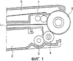
На Фиг.1 представлен вид примера проявочного узла, установленного в устройстве для формирования изображения.1 is a view of an example of a developing unit installed in an image forming apparatus.
Проявочный узел (см. Фиг.1) содержит корпус 2 для тонера, корпус 6 для отходов тонера и светочувствительное средство 5.The developing unit (see Figure 1) contains a
Тонер размещен в корпусе 2 для тонера и тонер подают к скрытому электростатическому изображению на светочувствительном средстве 5 с помощью подающего вала 3 и проявочного вала 4.The toner is housed in the
Тонер, подаваемый к скрытому электростатическому изображению, переносится на лист бумаги с помощью узла переноса, а отходы тонера, т.е. тонера, не перенесенного на лист бумаги, удаляют с помощью чистящего элемента 7, установленного в корпусе 6 для отходов тонера, и собирают в корпусе 6 для отходов тонера.The toner supplied to the latent electrostatic image is transferred onto a sheet of paper using the transfer unit, and the toner waste, i.e. toner not transferred to a sheet of paper is removed with a
Корпус 2 для тонера и корпус 6 для отходов тонера могут быть расположены в различных положениях. Для уменьшения объема проявочного узла корпус 2 для тонера и корпус 6 для отходов тонера могут быть расположены соответственно выше и ниже лазерного луча L, испускаемого узлом сканирования (не показан) лазерного луча, когда имеется пространство между корпусом 2 для тонера и корпусом 6 для отходов тонера, таким образом, чтобы лазерный луч L мог проходить, как это показано на Фиг.1.The
Внутренность корпуса 6 для отходов тонера может быть пустой до попадания туда отходов тонера, и поверхности стенок всех областей, за исключением области, на которой установлен чистящий элемент 7, могут быть термически скреплены друг с другом.The inside of the
Однако верхняя сторона корпуса 6 для отходов тонера выполнена в виде тонкой пластины таким образом, что может возникать вертикальный поток. Такая деформация корпуса 6 для отходов тонера может часто возникать при распределении продуктов или при присоединении и отсоединении проявочного узла. Если верхняя поверхность корпуса 6 для отходов тонера деформирована, то давление воздуха внутри корпуса 6 для отходов тонера может изменяться, и находящиеся в корпусе отходы тонера могут перемещаться в обратном направлении из корпуса 6 для отходов тонера.However, the upper side of the
Когда верхняя поверхность корпуса 6 для отходов тонера деформирована, положения чистящего элемента 7 и различных пленочных компонентов для уплотнения, установленных внутри корпуса, могут изменяться, что может вызвать нежелательный обратный поток отходов тонера из-за утечки воздуха или недостаточную чистку.When the upper surface of the
Кроме того, если верхняя поверхность корпуса 6 для отходов тонера деформирована из-за воздействия тепла внутри аппарата для формирования изображения, то может происходить воздействие смежного проявочного узла, которым создают другой цвет, расположенного с верхней стороны, в случае использования аппарата для формирования цветного изображения. Может быть сложной операция по присоединению или отсоединению проявочного узла из-за взаимного влияния между внутренними установочными компонентами в случае использования аппарата для формирования одноцветного изображения. Эти проблемы могут быть частично решены путем создания достаточного пространства между корпусом 2 для тонера и корпусом 6 для отходов тонера, но это вызывает нежелательное увеличение объема проявочного узла.In addition, if the upper surface of the
КРАТКОЕ ОПИСАНИЕ ИЗОБРЕТЕНИЯSUMMARY OF THE INVENTION
Согласно общей концепции настоящего изобретения создан проявочный узел, обладающий усовершенствованной конструкцией для предотвращения деформации, вызываемой воздействием тепла и давления, и устройство для формирования изображения, содержащее проявочный узел.According to the general concept of the present invention, a developing unit is provided having an improved design for preventing deformation caused by heat and pressure, and an image forming apparatus comprising a developing unit.
Дополнительные аспекты и полезные свойства общей концепции настоящего изобретения частично представлены в последующем описании и частично могут быть поняты при ознакомлении с описанием или могут быть изучены путем практического применения общей концепции изобретения.Additional aspects and useful properties of the general concept of the present invention are partially presented in the following description and partly can be understood by reading the description or can be studied by practical application of the general concept of the invention.
Указанные выше и/или другие аспекты и полезные свойства общей концепции настоящего изобретения могут быть достигнуты посредством создания проявочного узла, содержащего корпус для отходов тонера, содержащий: верхний корпус и нижний корпус, обращенные друг к другу; по меньшей мере, один поддерживающий узел для обеспечения возможности соединения верхнего и нижнего корпусов и для поддержания обращенных друг к другу поверхностей верхнего и нижнего корпусов; и корпус для тонера, расположенный в нижней части корпуса для отходов тонера и на предварительно определенном расстоянии от корпуса для отходов тонера.The above and / or other aspects and useful properties of the general concept of the present invention can be achieved by creating a developing unit comprising a toner waste container, comprising: an upper case and a lower case facing each other; at least one support node for enabling the connection of the upper and lower bodies and for supporting facing each other surfaces of the upper and lower bodies; and a toner body located at the bottom of the toner waste body and at a predetermined distance from the toner waste body.
По меньшей мере, один поддерживающий узел может содержать множество поддерживающих выступов и множество средств для введения выступов, взаимодополняюще расположенных на обращенных друг к другу поверхностях верхнего и нижнего корпусов.At least one support node may comprise a plurality of support protrusions and a plurality of means for introducing protrusions located mutually complementary on facing surfaces of the upper and lower bodies.
Поддерживающие выступы могут быть установлены на нижнем корпусе, а средства для введения выступов могут быть установлены на верхнем корпусе.Supporting protrusions may be mounted on the lower housing, and means for introducing protrusions may be mounted on the upper housing.
Каждый из поддерживающих выступов может содержать вводимую часть, имеющую крестообразную форму, передний конец которой снабжен фаской; и первую поддерживающую бобышку, выполненную с диаметром, большим длины главной оси вводимой части.Each of the supporting protrusions may comprise an insertion portion having a cruciform shape, the front end of which is chamfered; and the first supporting boss, made with a diameter greater than the length of the main axis of the input part.
Каждое из средств для введения выступа может содержать установочное углубление, в которое вставляют вводимую часть, и вторую поддерживающую бобышку, содержащую установочное углубление, выполненное в ней.Each of the means for introducing the protrusion may contain an installation recess in which the insertion part is inserted, and a second supporting boss containing the installation recess made therein.
Установочное углубление может иметь глубину, составляющую приблизительно 1 мм или менее.The installation recess may have a depth of approximately 1 mm or less.
Когда длина верхнего корпуса равна L, поддерживающий узел может быть расположен на расстоянии, меньшем 1/2 L, от светочувствительного средства. Кроме того, поддерживающие узлы могут быть линейно расположены с предварительно определенным интервалом в левом, центральном и правом положениях верхнего и нижнего корпусов.When the length of the upper case is L, the support unit may be located at a distance less than 1/2 L from the photosensitive means. In addition, the supporting nodes can be linearly spaced at a predetermined interval in the left, central and right positions of the upper and lower bodies.
Поддерживающие узлы могут дополнительно содержать поддерживающие ребра, выступающие от поддерживающих выступов. Каждое из поддерживающих ребер может иметь наклонную поверхность.Supporting nodes may further comprise supporting ribs protruding from the supporting protrusions. Each of the supporting ribs may have an inclined surface.
Наружные поверхности верхнего и нижнего корпусов могут быть сопряжены друг с другом таким образом, чтобы верхний и нижний корпуса могли быть термически прикреплены друг к другу.The outer surfaces of the upper and lower bodies can be mated with each other so that the upper and lower bodies can be thermally attached to each other.
Указанные выше и/или другие аспекты и полезные свойства общей концепции настоящего изобретения могут быть также достигнуты посредством создания устройства для формирования изображения, содержащего светочувствительное средство, на котором формируют скрытое электростатическое изображение; проявочный узел, описанный выше, для проявления скрытого электростатического изображения на светочувствительном средстве с использованием тонера; узел переноса для переноса изображения, проявленного на светочувствительном средстве, на средство для печатания; фиксирующий узел для сообщения тепла и приложения давления к средству для печатания и для фиксации изображения; и выпускной узел для выпуска средства для печатания, несущего изображение.The above and / or other aspects and useful properties of the general concept of the present invention can also be achieved by providing an image forming apparatus comprising a photosensitive means on which a latent electrostatic image is formed; a developing unit described above for developing a latent electrostatic image on a photosensitive using toner; a transfer unit for transferring an image developed on the photosensitive means to the printing means; a fixing unit for communicating heat and applying pressure to the printing means and for fixing the image; and an outlet assembly for releasing printing means carrying the image.
Указанные выше и/или другие аспекты и полезные свойства общей концепции настоящего изобретения могут быть также достигнуты путем создания проявочного картриджа, содержащего светочувствительное средство; контейнер для тонера для содержания в нем тонера для подачи тонера к светочувствительному средству; и контейнер для отходов тонера для содержания в нем отходов тонера, удаленных со светочувствительного средства; при этом контейнер для отходов тонера содержит первую стенку, являющуюся также наружной стенкой проявочного картриджа; вторую стенку, расположенную напротив первой и обращенную к первой стенке; и по меньшей мере, одну опору, расположенную внутри контейнера между первой и второй стенками.The above and / or other aspects and useful properties of the general concept of the present invention can also be achieved by creating a developing cartridge containing a photosensitive; a toner container for containing toner therein for supplying toner to a photosensitive; and a toner waste container for containing toner waste removed from the photosensitive means; wherein the toner waste container comprises a first wall, which is also the outer wall of the developing cartridge; a second wall opposite the first and facing the first wall; and at least one support located inside the container between the first and second walls.
Указанные выше и/или другие аспекты и полезные свойства общей концепции настоящего изобретения могут быть также достигнуты посредством создания проявочного картриджа, применимого с устройством для формирования изображения, содержащего светочувствительное средство; контейнер для тонера, для содержания в нем тонера, для подачи тонера к светочувствительному средству, и контейнер для отходов тонера, расположенный над контейнером для тонера и на расстоянии от контейнера для тонера и содержащий верхний и нижний корпуса для образования пространства для приема отходов тонера, удаленных со светочувствительного средства; при этом нижний корпус содержит первый край для контакта с верхним корпусом; второй край, снабженный чистящим элементом; и среднюю часть между первым краем и вторым краем для оснащения одним или большим числом опор для поддержания расстояния между верхним и нижним корпусами.The above and / or other aspects and useful properties of the general concept of the present invention can also be achieved by providing a developing cartridge applicable to an image forming apparatus comprising a photosensitive; a toner container, for containing toner therein, for supplying toner to the photosensitive, and a toner waste container located above the toner container and at a distance from the toner container and containing upper and lower bodies for creating a space for receiving toner waste removed with a photosensitive; wherein the lower case comprises a first edge for contacting the upper case; a second edge provided with a cleaning element; and the middle part between the first edge and the second edge to equip one or more supports to maintain the distance between the upper and lower bodies.
КРАТКОЕ ОПИСАНИЕ ЧЕРТЕЖЕЙBRIEF DESCRIPTION OF THE DRAWINGS
Эти и/или другие аспекты и полезные свойства общей концепции настоящего изобретения станут очевидными и их можно более легко оценить при ознакомлении с последующим описанием вариантов исполнения в сочетании с прилагаемыми чертежами, на которых изображено:These and / or other aspects and useful properties of the general concept of the present invention will become apparent and can be more easily appreciated by reading the following description of embodiments in combination with the accompanying drawings, in which:
на Фиг.1 - часть в разрезе обычного проявочного узла;figure 1 is a sectional view of a conventional developing unit;
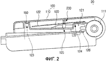
на Фиг.2 - проявочный узел в разрезе согласно примерному варианту исполнения общей концепции настоящего изобретения;figure 2 - developmental unit in the context according to an exemplary embodiment of the General concept of the present invention;
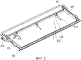
на Фиг.3 - вид в перспективе нижнего корпуса для отходов тонера проявочного узла, представленного на Фиг.2;figure 3 is a perspective view of the lower housing for waste toner of the developing unit shown in figure 2;
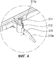
на Фиг.4 - вид в перспективе основных частей нижнего корпуса, представленного на Фиг.3;figure 4 is a perspective view of the main parts of the lower case shown in figure 3;
на Фиг.5 - вид снизу в перспективе верхнего корпуса, прикрепленного к нижнему корпусу, представленному на Фиг.3;figure 5 is a bottom perspective view of the upper case attached to the lower case shown in figure 3;
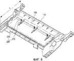
на Фиг.6 - вид снизу в перспективе корпуса для отходов тонера, содержащего верхний и нижний корпуса, прикрепленные друг к другу;FIG. 6 is a bottom perspective view of a toner waste body comprising upper and lower bodies attached to each other; FIG.
на Фиг.7 - вид устройства для формирования изображения, содержащего проявочный узел согласно примерному варианту исполнения общей концепции настоящего изобретения;7 is a view of an image forming apparatus comprising a developing unit according to an exemplary embodiment of the general concept of the present invention;
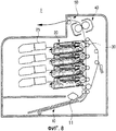
на Фиг.8 - вид устройства для формирования цветного изображения, содержащего множество проявочных узлов согласно примерному варианту исполнения общей концепции изобретения.Fig. 8 is a view of an apparatus for forming a color image comprising a plurality of developing nodes according to an exemplary embodiment of the general concept of the invention.
ПОДРОБНОЕ ОПИСАНИЕ ПРЕДПОЧТИТЕЛЬНЫХ ВАРИАНТОВ ИСПОЛНЕНИЯ ИЗОБРЕТЕНИЯDETAILED DESCRIPTION OF THE PREFERRED EMBODIMENTS OF THE INVENTION
Ниже подробно описаны варианты исполнения общей концепции настоящего изобретения, примеры которых показаны на прилагаемых чертежах, на которых одинаковыми номерами позиций повсеместно обозначены подобные элементы. Варианты исполнения описаны ниже со ссылками на чертежи для пояснения общей концепции настоящего изобретения.Embodiments of the general concept of the present invention are described in detail below, examples of which are shown in the accompanying drawings, in which like elements are universally designated by the same reference numerals. Embodiments are described below with reference to the drawings to explain the general concept of the present invention.
Проявочный узел согласно примерному варианту исполнения общей концепции настоящего изобретения содержит корпус 100 (см. Фиг.2) для отходов тонера; корпус 150 для тонера и поддерживающий узел 200.The developing unit according to an exemplary embodiment of the general concept of the present invention comprises a housing 100 (see FIG. 2) for toner waste; a
Корпус 100 для отходов тонера содержит верхний корпус 110 и нижний корпус 120. Наружные поверхности верхнего и нижнего корпусов 110 и 120 могут быть сопряжены друг с другом таким образом, чтобы верхний и нижний корпуса 110 и 120 могли быть термически прикреплены друг к другу. В соответствии с этим отходы тонера можно собирать во внутреннем пространстве, образованном между верхним и нижним корпусами 110 и 120. В верхнем корпусе 110 может быть установлено с возможностью вращения светочувствительное средство 111. Чистящий элемент 121 для чистки поверхности светочувствительного средства 111 может быть присоединен к нижнему корпусу 120. Элемент 122 для переноса отходов тонера установлен на поверхности для переноса отходов тонера чистящего элемента 121 таким образом, чтобы можно было перемещать его из стороны в сторону.The
Неиспользованный тонер может быть размещен в корпусе 150 для тонера, а корпус 150 для тонера может быть установлен в нижней части корпуса 100 для отходов тонера и на предварительно определенном расстоянии от корпуса 100 для отходов тонера таким образом, чтобы исключить столкновения с лазерным лучом, испускаемым узлом 25 для сканирования лазерного луча (см. Фиг.7), как это показано на Фиг.2.Unused toner can be housed in the
Нижний корпус 120 корпуса 100 для отходов тонера может содержать один край 123 для контакта или присоединения к верхнему корпусу 110, а другой край 124 присоединен или снабжен чистящим элементом 121. Другой край 124 нижнего корпуса 120 может быть присоединен или снабжен средним элементом 126 для поддержания нижнего корпуса 120 относительно корпуса 150 для тонера и/или для поддержания чистящего элемента 121 относительно нижнего корпуса 120. Поддерживающий узел 200 может быть образован в средней части 125 между одним краем 123 и другим краем 124.The
Как показано на Фиг.3-6, с помощью поддерживающих узлов 200 можно осуществлять соединение между верхним и нижним корпусами 110 и 120 и поддерживать верхний и нижний корпуса 110 и 120. Поддерживающие узлы 200 содержат множество поддерживающих выступов 210 и множество средств 220 для введения выступов, взаимодополняюще расположенных на поверхности, на которой верхний и нижний корпуса 110 и 120 обращены друг к другу. Поддерживающий узел 200 может быть установлен внутри корпуса 100 для отходов тонера и с его помощью можно предотвращать деформирование верхнего и нижнего корпусов 110 и 120 под воздействием тепла или давления.As shown in FIGS. 3-6, with the
Согласно примерному варианту исполнения поддерживающие выступы 210 могут быть установлены на нижнем корпусе 120, как показано на Фиг.3 и 4, а средства 220 для введения выступов могут быть установлены на верхнем корпусе 110, как показано на Фиг.5. Однако эти установочные положения могут быть переменены местами.According to an exemplary embodiment, the supporting
Каждый из поддерживающих выступов 210 содержит вводимую часть 211 и первую поддерживающую бобышку 212.Each of the supporting
Вводимая часть 211 может иметь крестообразную форму и на переднем конце вводимой части 211 может быть выполнена фаска 211a. Первая поддерживающая бобышка 212 может иметь диаметр, больший длины главной оси вводимой части 211, и может быть выполнена за одно целое с поддерживающим ребром 213, содержащим наклонную поверхность 213a. С помощью первой поддерживающей бобышки 212 можно поддерживать элемент 122 для переноса отходов тонера таким образом, чтобы элемент 122 для переноса отходов тонера можно было располагать под наклоном вниз.The
Каждое из средств 220 для введения выступов содержит установочное углубление 221 и вторую поддерживающую бобышку 222, как показано на Фиг.5.Each of the means for introducing the
Установочное углубление 221 может быть выполнено во второй поддерживающей бобышке 222, и она может иметь диаметр, соответствующий диаметру первой поддерживающей бобышки 212, и может иметь глубину, составляющую приблизительно 1 мм или менее. Установочное углубление 221 может иметь внутренний диаметр, равный длине главной оси вводимой части 211 таким образом, чтобы вводимую часть 211 можно было вставить в установочное углубление 221.The mounting
Один или большее число поддерживающих узлов 200, выполненных, как это указано выше, может быть установлено во внутреннем пространстве корпуса 100 для отходов тонера для повышения конструкционной жесткости корпуса 100 для отходов тонера. Посредством стенок верхнего и нижнего корпусов 110 и 120, термически прикрепленных друг к другу, можно также повысить конструкционную жесткость корпуса 100 для отходов тонера.One or
Если длина верхнего корпуса 110 (см. Фиг.6) равна L, то поддерживающий узел 200 может быть расположен на расстоянии, меньшем 1/2 L, от светочувствительного средства 111. Это объясняется тем, конструкционная жесткость верхнего корпуса 110 уменьшается из-за проема, образованного около места, обращенного к светочувствительному средству 111.If the length of the upper case 110 (see FIG. 6) is L, then the supporting
Как показано на Фиг.3-6, поддерживающие узлы 200 могут быть расположены линейно с предварительно определенным интервалом в левом, центральном и правом положениях верхнего и нижнего корпусов 110 и 120. В соответствии с этим с помощью поддерживающего узла 200, выполненного так, как указано выше, можно предотвращать деформацию, например, провис или наклон корпуса 100 для отходов тонера, и можно также направлять установку и перемещение элемента 122 для переноса отходов тонера, который устанавливают таким образом, чтобы можно было его перемещать из стороны в сторону.As shown in FIGS. 3-6, the
Ниже описано действие устройства для формирования изображения, содержащего проявочный узел согласно примерному варианту исполнения общей концепции настоящего изобретения со ссылками на Фиг.7.The following describes the operation of an image forming apparatus comprising a developing unit according to an exemplary embodiment of the general concept of the present invention with reference to FIG. 7.
Устройство 1 (см. Фиг.7) для формирования изображения согласно примерному варианту исполнения общей концепции настоящего изобретения содержит питающий узел 10, проявочный узел 20, узел 30 переноса, фиксирующий узел 40 и выпускной узел 50.An image forming apparatus 1 (see FIG. 7) according to an exemplary embodiment of the general concept of the present invention comprises a
Когда начинают печатание, листы бумаги, уложенные в питающем узле 10, могут быть переданы в проявочный узел 20 захватывающим узлом 11. С помощью узла 25 сканирования лазерного луча создают информацию печатного изображения посредством лазерного луча, и лазерный луч может быть направлен на светочувствительное средство 111 таким образом, что на поверхности светочувствительного средства может образовываться скрытое электростатическое изображение. С помощью проявочного узла 20 можно наносить тонер на скрытое электростатическое изображение для образования изображения из тонера, и светочувствительным средством 111 можно переносить изображение, образованное из тонера, на лист бумаги посредством вращения в плотном контакте с узлом 30 переноса. Тепло и давление можно сообщать с помощью фиксирующего узла 40 листу бумаги, на который перенесено изображение, образованное из тонера, а затем изображение, образованное из тонера, может быть закреплено на поверхности листа бумаги для завершения, таким образом, процесса печатания. Кроме того, лист бумаги, на котором закреплено изображение, образованное из тонера, может быть выпущен наружу из устройства 1 для формирования изображения с помощью выпускного узла 50.When printing begins, sheets of paper stacked in the
Для уменьшения объема проявочного узла корпус 100 для отходов тонера может быть расположен на расстоянии от корпуса 150 для тонера, который расположен под корпусом 100 для отходов тонера, и внутреннее пространство между корпусом 100 для отходов тонера и корпусом 150 для тонера может быть использовано как тракт для света для лазерного луча в проявочном узле 20 согласно примерному варианту исполнения. Таким образом, деформация корпуса 100 для отходов тонера под воздействием тепла или давления может создавать помехи на пути лазерного луча.To reduce the volume of the developing unit, the
Однако в корпусе 100 для отходов тонера согласно примерному варианту исполнения поверхностные стенки верхнего и нижнего корпусов 110 и 120, связанные друг с другом, могут быть термически прикреплены друг к другу, и конструкционная жесткость верхнего и нижнего корпусов 110 и 120 может быть повышена посредством установки, по меньшей мере, одного поддерживающего узла 200 во внутреннем пространстве. В соответствии с этим, даже если тепло, способное вызвать провис, наклон или какую-либо другую деформацию верхнего и нижнего корпусов 110 и 120, сообщают верхнему корпусу 110 или нижнему корпусу 120, деформация корпуса 100 для отходов тонера будет минимизирована. Таким образом, даже если световой тракт, образованный между корпусом 100 для отходов тонера и корпусом 150 для тонера, через который может проходить лазерный луч, является узким, не возникают проблемы, связанные с образованием помех.However, in the
Как показано на Фиг.8, проявочный узел 20, содержащий устройство для сбора отходов тонера согласно примерному варианту исполнения, может быть применен в аппарате для формирования цветного изображения. В этом примере четыре проявочных узла 20, содержащих желтый, пурпурный, голубой и черный тонеры, соответственно, установлены штабелем один над другим, как это показано на Фиг.8.As shown in FIG. 8, a developing
В штабеле проявочных узлов 20 проявочный узел 20 может сталкиваться со смежным проявочным узлом 20 при присоединении или отсоединении проявочного узла 20, таким образом, когда непреднамеренно прикладывают силу к корпусу 100 для отходов тонера. Однако любой силе, приложенной к верхнему корпусу 110, и любой силе от вертикально направленного толчка (например, при присоединении или отсоединении проявочного узла 20) противостоит нижний корпус 120 и, по меньшей мере, один поддерживающий узел 200. В соответствии с этим можно предотвратить изменение положений чистящего элемента 121 и различных пленочных компонентов для уплотнения, которые могли бы быть вызваны, если бы верхний корпус 110 был деформирован, и таким образом можно также предотвращать возникновение обратного потока отходов тонера из-за утечки воздуха.In a stack of developing
Согласно примерному варианту исполнения, описанному выше, можно предотвращать деформирование корпуса для отходов тонера под воздействием тепла и давления и, таким образом, можно снизить возможность появления белых линий на изображениях, обратного потока отходов тонера, недостаточной чистки и возникновения помех в световом тракте из-за деформации корпуса для отходов тонера.According to the exemplary embodiment described above, it is possible to prevent deformation of the toner waste body under the influence of heat and pressure, and thus, it is possible to reduce the possibility of white lines appearing in the images, the backflow of toner waste, insufficient cleaning and interference in the light path due to deformation of the case for toner waste.
Кроме того, могут быть значительно уменьшены допуски в результате решения проблемы деформации корпуса для отходов тонера, а также может быть создан проявочный узел меньшего размера.In addition, tolerances can be significantly reduced as a result of solving the problem of deformation of the case for waste toner, and a smaller developing unit can also be created.
Хотя представлено и описано небольшое число вариантов исполнения общей концепции настоящего изобретения, специалисты в данной области могут понять, что в эти варианты исполнения можно внести изменения без отступления от принципов и сущности общей концепции изобретения, объем которого определен в прилагаемой формуле изобретения и в ее эквивалентах.Although a small number of embodiments of the general concept of the present invention are presented and described, those skilled in the art can understand that changes can be made to these embodiments without departing from the principles and essence of the general concept of the invention, the scope of which is defined in the appended claims and their equivalents.
Claims (31)
- корпус для отходов тонера, содержащий верхний корпус и нижний корпус, которые обращены друг к другу;
- по меньшей мере, один поддерживающий узел, выступающий между верхним и нижним корпусами, для поддержания обращенных друг к другу поверхностей верхнего и нижнего корпусов; и
- корпус для тонера, расположенный на нижней части корпуса для отходов тонера и на предварительно определенном расстоянии от корпуса для отходов тонера.1. A developing unit of an image forming apparatus, comprising:
- a toner waste body comprising an upper body and a lower body that are facing each other;
- at least one support node protruding between the upper and lower bodies to support facing surfaces of the upper and lower bodies; and
- a toner body located on the lower part of the toner waste body and at a predetermined distance from the toner waste body.
- вводимую часть, имеющую крестообразную форму, передний конец которой снабжен фаской; и
- первую поддерживающую бобышку, имеющую ширину, большую длины главной оси вводимой части.4. The developing unit according to claim 3, in which each of the supporting protrusions contains:
- the input part having a cross-shaped shape, the front end of which is equipped with a bevel; and
- the first supporting boss having a width greater than the length of the main axis of the input part.
- установочное углубление, в которое вводят вводимую часть; и
- вторую поддерживающую бобышку, содержащую установочное углубление, выполненное в ней.5. The developing unit according to claim 4, in which each of the means for introducing the protrusion contains:
- installation recess in which the input part is inserted; and
- the second supporting boss containing the installation recess made in it.
- светочувствительное средство, на котором образуют скрытое электростатическое изображение;
- проявочный узел для проявления скрытого электростатического изображения на светочувствительном средстве с использованием тонера;
- узел переноса для переноса изображения, проявленного на светочувствительном средстве, на средство для печатания;
- фиксирующий узел для сообщения тепла и приложения давления к средству для печатания и фиксации изображения; и
- выпускной узел для выпуска средства для печатания, несущего изображение;
в котором проявочный узел содержит:
- корпус для отходов тонера, содержащий верхний корпус и нижний корпус, которые обращены друг к другу;
- по меньшей мере, один поддерживающий узел, выступающий между верхним и нижним корпусами, для поддержания обращенных друг к другу поверхностей верхнего и нижнего корпусов; и
- корпус для тонера, расположенный на нижней части корпуса для отходов тонера и на предварительно определенном расстоянии от корпуса для отходов тонера.12. An image forming apparatus, comprising:
- photosensitive means, which form a latent electrostatic image;
- a developing unit for developing a latent electrostatic image on a photosensitive means using toner;
a transfer unit for transferring an image developed on the photosensitive means to the printing means;
- a fixing unit for communicating heat and applying pressure to the means for printing and fixing the image; and
- an outlet assembly for releasing printing means carrying an image;
in which the developing unit contains:
- a toner waste body comprising an upper body and a lower body that are facing each other;
- at least one support node protruding between the upper and lower bodies to support facing surfaces of the upper and lower bodies; and
- a toner body located on the lower part of the toner waste body and at a predetermined distance from the toner waste body.
- вводимую часть, которая имеет крестообразную форму и передний конец которой снабжен фаской; и
- первую поддерживающую бобышку, имеющую ширину, большую длины главной оси вводимой части.15. The device according to 14, in which each of the supporting protrusions contains:
- the input part, which has a cross-shaped shape and the front end of which is chamfered; and
- the first supporting boss having a width greater than the length of the main axis of the input part.
- установочное углубление, в которое вводят вводимую часть; и
- вторую поддерживающую бобышку, содержащую установочное углубление, выполненное в ней.16. The device according to clause 15, in which each of the means for introducing the protrusion contains:
- the installation recess into which the input part is inserted; and
- the second supporting boss containing the installation recess made in it.
- тонер содержит множество тонеров;
- отходы тонера содержат множество отходов тонеров, соответствующих соответствующим тонерам; и
- проявочный узел содержит множество проявочных узлов таким образом, чтобы они соответствовали множеству тонеров для проявления скрытого электростатического изображения на светочувствительном средстве с использованием соответствующих тонеров из множества тонеров.23. The device according to item 12, in which:
- the toner contains many toners;
- waste toner contains many waste toners corresponding to the corresponding toners; and
- the developing unit contains a plurality of developing units so that they correspond to a plurality of toners for developing a latent electrostatic image on the photosensitive means using appropriate toners from the plurality of toners.
- светочувствительное средство;
- контейнер для тонера, для содержания в нем тонера, для подачи тонера к светочувствительному средству; и
- контейнер для отходов тонера, для содержания в нем отходов тонера, удаленного со светочувствительного средства, где контейнер для отходов тонера содержит: первую стенку, которая также является наружной стенкой проявочного картриджа; вторую стенку, расположенную напротив первой и обращенную к первой стенке, и, по меньшей мере, одну опору, расположенную внутри контейнера, выступающую между первой и второй стенками.24. Developing cartridge containing:
- photosensitive;
- a toner container, for containing toner therein, for supplying toner to a photosensitive means; and
- a toner waste container for containing toner waste removed from the photosensitive, where the toner waste container contains: a first wall, which is also the outer wall of the developing cartridge; a second wall opposite the first and facing the first wall, and at least one support located inside the container, protruding between the first and second walls.
- чистящий узел, расположенный рядом со светочувствительным средством, для удаления отходов тонера со светочувствительного средства;
в котором контейнер для отходов тонера содержит проем для приема отходов тонера, удаленных со светочувствительного средства чистящим узлом; и, по меньшей мере, одну опору, расположенную около или ближе расстояния 1/2L, где L является длиной контейнера для отходов тонера в направлении, перпендикулярном оси светочувствительного средства.25. The developing cartridge according to paragraph 24, further comprising:
- a cleaning unit located next to the photosensitive, to remove toner waste from the photosensitive;
wherein the toner waste container comprises an opening for receiving toner waste removed from the photosensitive means by the cleaning unit; and at least one support located near or closer to a distance of 1/2 L, where L is the length of the toner waste container in a direction perpendicular to the axis of the photosensitive.
Applications Claiming Priority (2)
| Application Number | Priority Date | Filing Date | Title |
|---|---|---|---|
| KR1020070029973A KR100930044B1 (en) | 2007-03-27 | 2007-03-27 | Developing unit of the image forming apparatus |
| KR2007-29973 | 2007-03-27 |
Publications (2)
| Publication Number | Publication Date |
|---|---|
| RU2008111642A RU2008111642A (en) | 2009-10-10 |
| RU2460109C2 true RU2460109C2 (en) | 2012-08-27 |
Family
ID=39598456
Family Applications (1)
| Application Number | Title | Priority Date | Filing Date |
|---|---|---|---|
| RU2008111642/28A RU2460109C2 (en) | 2007-03-27 | 2008-03-26 | Developing unit and device for formation of image containing such unit |
Country Status (6)
| Country | Link |
|---|---|
| US (1) | US7840171B2 (en) |
| EP (2) | EP1975744B2 (en) |
| KR (1) | KR100930044B1 (en) |
| CN (1) | CN101276182B (en) |
| ES (2) | ES2429104T5 (en) |
| RU (1) | RU2460109C2 (en) |
Families Citing this family (3)
| Publication number | Priority date | Publication date | Assignee | Title |
|---|---|---|---|---|
| KR100930044B1 (en) † | 2007-03-27 | 2009-12-08 | 삼성전자주식회사 | Developing unit of the image forming apparatus |
| JP7102940B2 (en) * | 2018-05-24 | 2022-07-20 | ブラザー工業株式会社 | Image forming device |
| KR102390146B1 (en) * | 2018-08-30 | 2022-04-25 | 휴렛-팩커드 디벨롭먼트 컴퍼니, 엘.피. | Structure to refill toner to development cartridge mounted in main body |
Citations (2)
| Publication number | Priority date | Publication date | Assignee | Title |
|---|---|---|---|---|
| EP1184740A2 (en) * | 2000-08-28 | 2002-03-06 | Oki Data Corporation | Toner cartridge and image forming apparatus |
| RU2207958C2 (en) * | 1998-03-16 | 2003-07-10 | Хьюлетт-Паккард Компани | Modular jet printer |
Family Cites Families (29)
| Publication number | Priority date | Publication date | Assignee | Title |
|---|---|---|---|---|
| US4768055A (en) | 1986-06-17 | 1988-08-30 | Mita Industrial Co., Ltd. | Image forming machine having a toner recycling unit |
| JPH04263273A (en) | 1991-02-17 | 1992-09-18 | Ricoh Co Ltd | Image forming device |
| US5852762A (en) | 1993-01-12 | 1998-12-22 | Ricoh Company, Ltd. | Toner magazine and cleaner for an electrophotographic apparatus |
| JP3285414B2 (en) † | 1993-04-28 | 2002-05-27 | キヤノン株式会社 | Process cartridge and image forming apparatus |
| KR0133715Y1 (en) * | 1993-10-30 | 1999-03-30 | 김광호 | Paper separation device of image former |
| US5426493A (en) † | 1994-04-22 | 1995-06-20 | National Laser Technologies, Inc. | Removable lid apparatus for toner cartridge and method of use |
| US5943528A (en) † | 1995-04-28 | 1999-08-24 | Canon Kabushiki Kaisha | Toner accommodating container with a gripping cover feature usable with a process cartridge, a process cartridge using the same, and an apparatus using the process cartridge |
| KR100234385B1 (en) | 1996-08-20 | 1999-12-15 | 윤종용 | Circuit for burn-in stressing for semiconductor memory device |
| JP3466831B2 (en) * | 1996-08-29 | 2003-11-17 | キヤノン株式会社 | Process cartridge and electrophotographic image forming apparatus |
| KR200145836Y1 (en) * | 1996-09-06 | 1999-06-15 | 이내웅 | Cleaning blade fixing device for sensitizer |
| JPH10153932A (en) | 1996-11-25 | 1998-06-09 | Ricoh Co Ltd | Cleaning device |
| JP3413173B2 (en) † | 2000-01-05 | 2003-06-03 | キヤノン株式会社 | Process cartridge and electrophotographic image forming apparatus |
| JP2003258181A (en) † | 2002-03-04 | 2003-09-12 | Nec Kansai Ltd | Positioning device |
| JP2005043537A (en) * | 2003-07-25 | 2005-02-17 | Canon Inc | Process cartridge and image forming apparatus using the same |
| JP3844245B2 (en) † | 2003-07-28 | 2006-11-08 | 船井電機株式会社 | projector |
| JP2005077614A (en) * | 2003-08-29 | 2005-03-24 | Canon Inc | Process cartridge and image forming apparatus |
| JP2005227318A (en) * | 2004-02-10 | 2005-08-25 | Canon Inc | Process cartridge and image forming apparatus |
| KR100601694B1 (en) * | 2004-07-20 | 2006-07-14 | 삼성전자주식회사 | Waste toner collecting apparatus, and electrophotographic image forming apparatus therewith |
| JP4608994B2 (en) * | 2004-08-11 | 2011-01-12 | 富士ゼロックス株式会社 | Image forming apparatus |
| KR101063407B1 (en) * | 2004-08-17 | 2011-09-07 | 삼성전자주식회사 | Process Cartridges and Recycling Process Cartridges |
| JP4815932B2 (en) † | 2004-10-29 | 2011-11-16 | ブラザー工業株式会社 | Process cartridge and image forming apparatus |
| KR100667322B1 (en) * | 2005-01-19 | 2007-01-12 | 삼성전자주식회사 | Used toner transporting apparatus and Toner cartridge having the same |
| KR100584617B1 (en) * | 2005-01-20 | 2006-05-30 | 삼성전자주식회사 | Developing cartridge and electrophotographic image forming apparatus using the same |
| KR100653086B1 (en) * | 2005-01-21 | 2006-12-01 | 삼성전자주식회사 | Used toner pulverizing apparatus and Toner cartridge having the same |
| JP4715263B2 (en) * | 2005-03-25 | 2011-07-06 | 富士ゼロックス株式会社 | Cleaning device, process cartridge using the same, and image forming apparatus |
| KR100705384B1 (en) * | 2005-08-16 | 2007-04-10 | 삼성전자주식회사 | Process Cartridge in an Image Forming Apparatus |
| KR100903793B1 (en) † | 2007-03-12 | 2009-06-19 | 삼성전자주식회사 | Waste toner transfer apparatus and waste toner cleaning device and developing unit having waste toner cleaning device and Image forming apparatus and waste toner removing method |
| KR100906340B1 (en) * | 2007-03-27 | 2009-07-06 | 삼성전자주식회사 | Cleaning apparatus and image forming apparatus having the same |
| KR100930044B1 (en) † | 2007-03-27 | 2009-12-08 | 삼성전자주식회사 | Developing unit of the image forming apparatus |
-
2007
- 2007-03-27 KR KR1020070029973A patent/KR100930044B1/en active IP Right Grant
- 2007-10-18 US US11/874,423 patent/US7840171B2/en active Active
-
2008
- 2008-01-21 CN CN2008100046508A patent/CN101276182B/en active Active
- 2008-03-11 EP EP08152593.3A patent/EP1975744B2/en active Active
- 2008-03-11 ES ES08152593.3T patent/ES2429104T5/en active Active
- 2008-03-11 EP EP12193890.6A patent/EP2597532B8/en active Active
- 2008-03-11 ES ES12193890.6T patent/ES2528153T3/en active Active
- 2008-03-26 RU RU2008111642/28A patent/RU2460109C2/en active
Patent Citations (2)
| Publication number | Priority date | Publication date | Assignee | Title |
|---|---|---|---|---|
| RU2207958C2 (en) * | 1998-03-16 | 2003-07-10 | Хьюлетт-Паккард Компани | Modular jet printer |
| EP1184740A2 (en) * | 2000-08-28 | 2002-03-06 | Oki Data Corporation | Toner cartridge and image forming apparatus |
Also Published As
| Publication number | Publication date |
|---|---|
| EP2597532B8 (en) | 2015-04-15 |
| US20080240814A1 (en) | 2008-10-02 |
| KR20080087553A (en) | 2008-10-01 |
| KR100930044B1 (en) | 2009-12-08 |
| EP1975744B1 (en) | 2013-07-24 |
| CN101276182A (en) | 2008-10-01 |
| CN101276182B (en) | 2013-01-30 |
| ES2429104T3 (en) | 2013-11-13 |
| EP2597532B1 (en) | 2014-12-03 |
| RU2008111642A (en) | 2009-10-10 |
| ES2429104T5 (en) | 2017-08-18 |
| ES2528153T3 (en) | 2015-02-04 |
| EP2597532A2 (en) | 2013-05-29 |
| US7840171B2 (en) | 2010-11-23 |
| EP2597532A3 (en) | 2013-11-20 |
| EP1975744A1 (en) | 2008-10-01 |
| EP1975744B2 (en) | 2017-03-01 |
Similar Documents
| Publication | Publication Date | Title |
|---|---|---|
| US8175492B2 (en) | Developer unit and image forming device | |
| JP2010044363A (en) | Image forming apparatus | |
| US11402770B2 (en) | Seal for an electrophotographic image forming device | |
| RU2460109C2 (en) | Developing unit and device for formation of image containing such unit | |
| US11579562B2 (en) | Image-forming apparatus provided with urging member for urging process cartridge | |
| JP5645868B2 (en) | Developer container, developing device including the same, and image forming apparatus | |
| US9791827B2 (en) | Image forming apparatus including cartridge for protecting photosensitive drum | |
| US20060127126A1 (en) | Developing apparatus | |
| JP2007232927A (en) | Image forming apparatus | |
| US6892040B2 (en) | Cooling apparatus of an image forming apparatus | |
| EP0893743A1 (en) | Developing unit equipped with an air vent for controlling an internal pressure | |
| US11614705B2 (en) | Mounting/demounting structure, apparatus using mounting/demounting structure, and mountable/demountable object | |
| JP2005301077A (en) | Developing unit | |
| JP4538300B2 (en) | Image forming apparatus | |
| KR100938847B1 (en) | Developing unit and image forming apparatus having the same | |
| JPH08171335A (en) | Image forming device, process cartridge, developing device and developer replenishing container | |
| JP4413110B2 (en) | Optical writing apparatus and image forming apparatus | |
| JP2007101717A (en) | Image forming unit and apparatus therefor | |
| WO2016129730A1 (en) | Compact, upright electrophotographic apparatus | |
| KR20050037932A (en) | Toner cartridge of electrophotographic image forming apparatus |
Legal Events
| Date | Code | Title | Description |
|---|---|---|---|
| PD4A | Correction of name of patent owner | ||
| PC41 | Official registration of the transfer of exclusive right |
Effective date: 20170522 |
|
| PD4A | Correction of name of patent owner |