RU2455031C2 - Ventilation apparatus and method enabling ability to speak with or without back-flow valve of tracheostomy tube - Google Patents
Ventilation apparatus and method enabling ability to speak with or without back-flow valve of tracheostomy tubeInfo
- Publication number
- RU2455031C2 RU2455031C2 RU2009113599/14A RU2009113599A RU2455031C2 RU 2455031 C2 RU2455031 C2 RU 2455031C2 RU 2009113599/14 A RU2009113599/14 A RU 2009113599/14A RU 2009113599 A RU2009113599 A RU 2009113599A RU 2455031 C2 RU2455031 C2 RU 2455031C2
- Authority
- RU
- Russia
- Prior art keywords
- patient
- valve
- exhalation
- inspiratory
- phase
- Prior art date
Links
Images

Classifications
-
- A—HUMAN NECESSITIES
- A61—MEDICAL OR VETERINARY SCIENCE; HYGIENE
- A61M—DEVICES FOR INTRODUCING MEDIA INTO, OR ONTO, THE BODY; DEVICES FOR TRANSDUCING BODY MEDIA OR FOR TAKING MEDIA FROM THE BODY; DEVICES FOR PRODUCING OR ENDING SLEEP OR STUPOR
- A61M16/00—Devices for influencing the respiratory system of patients by gas treatment, e.g. mouth-to-mouth respiration; Tracheal tubes
- A61M16/04—Tracheal tubes
- A61M16/0465—Tracheostomy tubes; Devices for performing a tracheostomy; Accessories therefor, e.g. masks, filters
- A61M16/0468—Tracheostomy tubes; Devices for performing a tracheostomy; Accessories therefor, e.g. masks, filters with valves at the proximal end limiting exhalation, e.g. during speaking or coughing
-
- A—HUMAN NECESSITIES
- A61—MEDICAL OR VETERINARY SCIENCE; HYGIENE
- A61M—DEVICES FOR INTRODUCING MEDIA INTO, OR ONTO, THE BODY; DEVICES FOR TRANSDUCING BODY MEDIA OR FOR TAKING MEDIA FROM THE BODY; DEVICES FOR PRODUCING OR ENDING SLEEP OR STUPOR
- A61M16/00—Devices for influencing the respiratory system of patients by gas treatment, e.g. mouth-to-mouth respiration; Tracheal tubes
- A61M16/04—Tracheal tubes
- A61M16/0402—Special features for tracheal tubes not otherwise provided for
- A61M16/042—Special features for tracheal tubes not otherwise provided for with separate conduits for in-and expiration gas, e.g. for limited dead volume
-
- A—HUMAN NECESSITIES
- A61—MEDICAL OR VETERINARY SCIENCE; HYGIENE
- A61M—DEVICES FOR INTRODUCING MEDIA INTO, OR ONTO, THE BODY; DEVICES FOR TRANSDUCING BODY MEDIA OR FOR TAKING MEDIA FROM THE BODY; DEVICES FOR PRODUCING OR ENDING SLEEP OR STUPOR
- A61M16/00—Devices for influencing the respiratory system of patients by gas treatment, e.g. mouth-to-mouth respiration; Tracheal tubes
- A61M16/08—Bellows; Connecting tubes ; Water traps; Patient circuits
- A61M16/0816—Joints or connectors
- A61M16/0833—T- or Y-type connectors, e.g. Y-piece
-
- A—HUMAN NECESSITIES
- A61—MEDICAL OR VETERINARY SCIENCE; HYGIENE
- A61M—DEVICES FOR INTRODUCING MEDIA INTO, OR ONTO, THE BODY; DEVICES FOR TRANSDUCING BODY MEDIA OR FOR TAKING MEDIA FROM THE BODY; DEVICES FOR PRODUCING OR ENDING SLEEP OR STUPOR
- A61M16/00—Devices for influencing the respiratory system of patients by gas treatment, e.g. mouth-to-mouth respiration; Tracheal tubes
- A61M16/20—Valves specially adapted to medical respiratory devices
- A61M16/201—Controlled valves
- A61M16/202—Controlled valves electrically actuated
- A61M16/203—Proportional
- A61M16/204—Proportional used for inhalation control
-
- A—HUMAN NECESSITIES
- A61—MEDICAL OR VETERINARY SCIENCE; HYGIENE
- A61M—DEVICES FOR INTRODUCING MEDIA INTO, OR ONTO, THE BODY; DEVICES FOR TRANSDUCING BODY MEDIA OR FOR TAKING MEDIA FROM THE BODY; DEVICES FOR PRODUCING OR ENDING SLEEP OR STUPOR
- A61M16/00—Devices for influencing the respiratory system of patients by gas treatment, e.g. mouth-to-mouth respiration; Tracheal tubes
- A61M16/20—Valves specially adapted to medical respiratory devices
- A61M16/201—Controlled valves
- A61M16/202—Controlled valves electrically actuated
- A61M16/203—Proportional
- A61M16/205—Proportional used for exhalation control
-
- A—HUMAN NECESSITIES
- A61—MEDICAL OR VETERINARY SCIENCE; HYGIENE
- A61M—DEVICES FOR INTRODUCING MEDIA INTO, OR ONTO, THE BODY; DEVICES FOR TRANSDUCING BODY MEDIA OR FOR TAKING MEDIA FROM THE BODY; DEVICES FOR PRODUCING OR ENDING SLEEP OR STUPOR
- A61M16/00—Devices for influencing the respiratory system of patients by gas treatment, e.g. mouth-to-mouth respiration; Tracheal tubes
- A61M16/0003—Accessories therefor, e.g. sensors, vibrators, negative pressure
- A61M2016/0015—Accessories therefor, e.g. sensors, vibrators, negative pressure inhalation detectors
- A61M2016/0018—Accessories therefor, e.g. sensors, vibrators, negative pressure inhalation detectors electrical
- A61M2016/0021—Accessories therefor, e.g. sensors, vibrators, negative pressure inhalation detectors electrical with a proportional output signal, e.g. from a thermistor
-
- A—HUMAN NECESSITIES
- A61—MEDICAL OR VETERINARY SCIENCE; HYGIENE
- A61M—DEVICES FOR INTRODUCING MEDIA INTO, OR ONTO, THE BODY; DEVICES FOR TRANSDUCING BODY MEDIA OR FOR TAKING MEDIA FROM THE BODY; DEVICES FOR PRODUCING OR ENDING SLEEP OR STUPOR
- A61M16/00—Devices for influencing the respiratory system of patients by gas treatment, e.g. mouth-to-mouth respiration; Tracheal tubes
- A61M16/0003—Accessories therefor, e.g. sensors, vibrators, negative pressure
- A61M2016/0027—Accessories therefor, e.g. sensors, vibrators, negative pressure pressure meter
-
- A—HUMAN NECESSITIES
- A61—MEDICAL OR VETERINARY SCIENCE; HYGIENE
- A61M—DEVICES FOR INTRODUCING MEDIA INTO, OR ONTO, THE BODY; DEVICES FOR TRANSDUCING BODY MEDIA OR FOR TAKING MEDIA FROM THE BODY; DEVICES FOR PRODUCING OR ENDING SLEEP OR STUPOR
- A61M39/00—Tubes, tube connectors, tube couplings, valves, access sites or the like, specially adapted for medical use
- A61M39/10—Tube connectors; Tube couplings
- A61M2039/1005—Detection of disconnection
-
- A—HUMAN NECESSITIES
- A61—MEDICAL OR VETERINARY SCIENCE; HYGIENE
- A61M—DEVICES FOR INTRODUCING MEDIA INTO, OR ONTO, THE BODY; DEVICES FOR TRANSDUCING BODY MEDIA OR FOR TAKING MEDIA FROM THE BODY; DEVICES FOR PRODUCING OR ENDING SLEEP OR STUPOR
- A61M2202/00—Special media to be introduced, removed or treated
- A61M2202/02—Gases
- A61M2202/0208—Oxygen
Abstract
Description
Эта заявка относится к вентиляции пациента, а именно к способу и аппарату для инвазивной вентиляции пациента, в котором используется устройство с эндотрахеальной трубкой и устройство для вентиляции.This application relates to the ventilation of a patient, and in particular to a method and apparatus for invasive ventilation of a patient in which a device with an endotracheal tube and a device for ventilation are used.
Уровень техникиState of the art
Пример известного устройства с эндотрахеальной трубкой раскрыт в патенте США № 4759356 ("патент '356"), полное описание которого приведено в качестве ссылки в настоящем описании. Пример известного устройства для вентиляции раскрыт в патенте США № 6543449 ("патент '449"), полное описание которого приведено в качестве ссылки в настоящем описании.An example of a known endotracheal tube device is disclosed in US Pat. No. 4,759,356 (“the '356 patent”), the entire disclosure of which is incorporated herein by reference. An example of a known ventilation device is disclosed in US patent No. 6543449 ("patent '449"), the full description of which is incorporated by reference in the present description.
Устройство с эндотрахеальной трубкой, раскрытое в патенте '356, включает в себя эндотрахеальную трубку, приспособленную для установки в трахею пациента таким образом, чтобы внутренний открытый конец сообщался с дыхательными путями и легкими пациента, а наружный открытый конец соответственно был зафиксирован снаружи на шее пациента. В патенте '356 раскрыто обеспечение открытого конца трубки обратным клапаном, часто называемым в области техники как "разговорный клапан". Обратный клапан, раскрытый в патенте '356, широко применяется, и в описании патента '356 указывается множество преимуществ обратного клапана при использовании в дополнение к основной преимущественной разговорной функции.The endotracheal tube device disclosed in the '356 patent includes an endotracheal tube adapted to be inserted into the patient’s trachea so that the inner open end communicates with the patient’s airways and lungs, and the outer open end is respectively secured externally on the patient’s neck. The '356 patent discloses providing an open end of a tube with a check valve, often referred to in the art as a "check valve." The non-return valve disclosed in the '356 patent is widely used, and the' 356 patent discloses many of the advantages of a non-return valve when used in addition to the primary advantageous conversational function.
Устройство для вентиляции, раскрытое в патенте '449, можно использовать инвазивно, например с устройством с эндотрахеальной трубкой, или использовать неинвазивно, например с маской. Настоящее изобретение сфокусировано на инвазивном способе работы устройства для вентиляции.The ventilation device disclosed in the '449 patent can be used invasively, for example with a device with an endotracheal tube, or used non-invasively, for example with a mask. The present invention is focused on an invasive method of operating a ventilation device.
Как заявлено в патенте '356, при использовании обратного клапана в дополнение к возможности говорить существует много других преимуществ. Однако существуют и недостатки. Например, обратный клапан необходимо удалять для возможности введения пациенту аэрозольных терапевтических средств или проведения процедуры аспирации.As stated in the '356 patent, there are many other advantages to using a non-return valve in addition to being able to talk. However, there are disadvantages. For example, a check valve must be removed to allow aerosol therapeutic agents to be administered to the patient or an aspiration procedure.
Настоящее изобретение относится к способу, с помощью которого можно получить преимущества обратного клапана в эндотрахеальной трубке без его недостатков. Способ изобретения относится к способу контроля устройства для вентиляции, имеющего трубку, снабженную каналами вдоха и выдоха, сообщающиеся друг с другом, и устройство для респирации, способное осуществлять повторные респираторные циклы, каждый из которых включает (1) фазу вдоха, во время которой клапан вдоха в канале вдоха относительно открыт для прохождения газа через него в канал вдоха и к пациенту, а клапан выдоха между каналом выдоха и выходным отверстием выдоха в устройстве для вентиляции относительно закрыт, и (2) фазу выдоха, во время которой клапан вдоха относительно закрыт.The present invention relates to a method by which the advantages of a non-return valve in an endotracheal tube can be obtained without its disadvantages. The method of the invention relates to a method for controlling a ventilation device having a tube provided with inspiratory and expiratory channels communicating with each other, and a respiratory device capable of performing repeated respiratory cycles, each of which includes (1) the inspiratory phase, during which the inspiratory valve in the inspiration channel is relatively open for gas to pass through it into the inspiration channel and to the patient, and the exhalation valve between the exhalation channel and the exhalation outlet in the ventilation device is relatively closed, and (2) the exhalation phase, while Namely, the inspiratory valve is relatively closed.
В примере варианта осуществления способ включает этапы соединения трубки с наружным открытым концом эндотрахеальной трубки, расположенной в трахее пациента, таким образом, чтобы внутренний открытый конец проходил в дыхательные пути и легкие пациента ниже голосовых связок пациента. Устройство для респирации повторяет циклы таким образом, что во время фазы вдоха газ в канале вдоха поступает через эндотрахеальную трубку в дыхательные пути и легкие пациента, а во время фазы выдоха клапан выдоха удерживается относительно закрытым и пациент способен выдыхать газы из дыхательных путей и легких таким образом, что газы проходят через голосовые связки пациента и выходят из ротовой полости пациента, таким образом облегчая способность пациента говорить. Давление, по меньшей мере, в одном из каналов подвергается мониторингу во время обеих фаз с целью определения давления в дыхательных путях и легких пациента с целью контроля устройства для вентиляции.In an example embodiment, the method includes the steps of connecting the tube to the outer open end of the endotracheal tube located in the patient’s trachea so that the inner open end extends into the patient’s airways and lungs below the patient’s vocal cords. The respiratory device repeats the cycles in such a way that during the inspiratory phase the gas in the inspiratory channel enters through the endotracheal tube into the patient’s airways and lungs, and during the exhalation phase, the exhalation valve is kept relatively closed and the patient is able to exhale gases from the airways and lungs in this way that gases pass through the patient’s vocal cords and exit the patient’s oral cavity, thereby facilitating the patient’s ability to speak. The pressure in at least one of the channels is monitored during both phases in order to determine the pressure in the airways and lungs of the patient in order to control the ventilation device.
В одном варианте осуществления изобретения эндотрахеальная трубка лишена обратного клапана, чтобы газ, выдыхаемый пациентом во время каждой фазы выдоха, поступал в каналы, при закрытых клапанах вдоха и выдоха.In one embodiment of the invention, the endotracheal tube is devoid of a check valve so that the gas exhaled by the patient during each phase of exhalation enters the channels when the inspiratory and expiratory valves are closed.
Изобретение также относится к аппарату для вентиляции пациента для осуществления способа, как описано выше. Аппарат включает комбинацию следующих компонентов. Эндотрахеальная трубка создана и приспособлена для установки через трахею пациента ниже голосовых связок пациента таким образом, чтобы наружный открытый конец ее находился вне пациента, а ее внутренний открытый конец сообщался с дыхательными путями и легкими пациента. Предусматривают устройство для вентиляции, которое включает трубку, связанную с внешним открытым концом эндотрахеальной трубки, снабженную каналами вдоха и выдоха, сообщающимися друг с другом. Клапаны вдоха и выдоха установлены соответственно в каналах вдоха и выдоха.The invention also relates to an apparatus for ventilating a patient to carry out the method as described above. The device includes a combination of the following components. The endotracheal tube is designed and adapted for installation through the patient’s trachea below the patient’s vocal cords so that its external open end is outside the patient and its internal open end communicates with the patient’s airways and lungs. A ventilation device is provided that includes a tube connected to the external open end of the endotracheal tube, provided with inspiration and expiration channels communicating with each other. The inspiration and expiration valves are installed respectively in the inspiration and expiration channels.
Устройство для вентиляции сконструировано для обеспечения повторных респираторных циклов, каждый из которых включает фазу вдоха, во время которой клапан вдоха относительно открыт, а клапан выдоха относительно закрыт, и поток газа может проходить через канал вдоха и эндотрахеальную трубку в дыхательные пути и легкие пациента. Также предоставляется регулятор для контроля клапана вдоха и клапана выдоха, и клапан выдоха работает в одном режиме фазы выдоха, выбранном из следующих двух: (1) первый режим, в котором клапан выдоха относительно открыт во время фазы выдоха, позволяя газу из дыхательных путей и легких пациента после предшествующей фазы вдоха проходить через открытый клапан выдоха и выходное отверстие устройства для вентиляции; и (2) второй режим, при котором клапан выдоха удерживается относительно закрытым, и пациент вызывает поступление газа из дыхательных путей и легких пациента после предшествующей фазы вдоха через голосовые связки пациента и выход его из ротового отверстия пациента, таким образом облегчая способность пациента говорить.The ventilation device is designed to provide repeated respiratory cycles, each of which includes the inspiratory phase, during which the inspiratory valve is relatively open and the exhalation valve is relatively closed, and the gas flow can pass through the inspiration channel and endotracheal tube into the patient’s airways and lungs. A regulator is also provided to control the inspiratory valve and the exhalation valve, and the exhalation valve operates in one exhalation phase mode selected from the following two: (1) the first mode in which the exhalation valve is relatively open during the exhalation phase, allowing gas from the airways and lungs after the previous phase of inspiration, the patient passes through the open exhalation valve and the outlet of the ventilation device; and (2) a second mode in which the exhalation valve is kept relatively closed and the patient causes gas to flow from the patient’s airways and lungs after the previous phase of inhalation through the patient’s vocal cords and out of the patient’s mouth, thereby facilitating the patient’s ability to speak.
Устройство для вентиляции также включает конструкцию для мониторинга давления, оперативно связанную с каналами, с целью определения существующего состояния давления в дыхательных путях и легких пациента для использования с помощью регулятора при контроле устройства для вентиляции. В одном варианте осуществления эндотрахеальная трубка лишена обратного клапана, так что связь между каналами и дыхательными путями и легкими пациента, в то время как клапан выдоха находится в неразговорном режиме, осуществляется через открытый конец эндотрахеальной трубки в обоих направлениях.The ventilation device also includes a design for monitoring pressure, operatively associated with the channels, in order to determine the existing state of pressure in the respiratory tract and lungs of the patient for use with the controller to control the ventilation device. In one embodiment, the endotracheal tube is devoid of a check valve, so that the connection between the canals and the airways and lungs of the patient, while the exhalation valve is in non-negotiable mode, is through the open end of the endotracheal tube in both directions.
Как указано выше, использование эндотрахеальной трубки, лишенной обратного клапана, является одним из аспектов настоящего изобретения, который обеспечивает разговорную функцию без известных недостатков обратных клапанов. Однако другой аспект настоящего изобретения относится к обеспечению аппарата для вентиляции, который позволяет избежать многих из известных недостатков использования обратного клапана, даже если обратный клапан присутствует в эндотрахеальной трубке.As indicated above, the use of an endotracheal tube devoid of a non-return valve is one aspect of the present invention that provides spoken function without the known disadvantages of non-return valves. However, another aspect of the present invention relates to providing a ventilation apparatus that avoids many of the known disadvantages of using a non-return valve, even if a non-return valve is present in the endotracheal tube.
В другом варианте осуществления изобретения аппарат для вентиляции включает следующие компоненты. Эндотрахеальная трубка сконструирована с возможностью установки в трахею пациента ниже голосовых связок пациента таким образом, чтобы ее наружный открытый конец находился вне пациента, а ее внутренний открытый конец сообщался с дыхательными путями и легкими пациента. Устройство для вентиляции, включающее трубку, соединенную с наружным открытым концом трубки и предоставляющую каналы вдоха и выдоха, сообщающиеся друг с другом, клапаны вдоха и выдоха, соответственно, в каналах вдоха и выдоха, и устройство для респирации, созданное и приспособленное для обеспечения повторяющихся респираторных циклов, каждый из которых включает (1) фазу вдоха, во время которой клапан вдоха в канале вдоха относительно открыт, а клапан выдоха в канале выдоха относительно закрыт, и поток газа может проходить через канал вдоха и трубку в дыхательные пути и легкие пациента и (2) фазу выдоха, во время которой клапан вдоха относительно закрыт, а клапан выдоха удерживается относительно закрытым.In another embodiment, the ventilation apparatus includes the following components. The endotracheal tube is designed to fit into the patient’s trachea below the patient’s vocal cords so that its external open end is outside the patient and its internal open end communicates with the patient’s airways and lungs. A ventilation device comprising a tube connected to the outer open end of the tube and providing inspiratory and expiratory channels communicating with each other, inspiratory and expiratory valves, respectively, in the inspiratory and expiratory channels, and a respiratory device designed and adapted to provide repetitive respiratory cycles, each of which includes (1) the inspiratory phase, during which the inspiratory valve in the inspiratory channel is relatively open, and the exhalation valve in the exhalation channel is relatively closed, and the gas flow can pass through the inspiratory channel tube in the airways and lungs of a patient, and (2) an exhalation phase during which the inspiratory valve is relatively closed, and the exhaust valve is kept relatively closed.
В своем наружном открытом конце эндотрахеальная трубка имеет обратный клапан, позволяющий пациенту в конце каждой фазы вдоха вызывать прохождение газа из дыхательных путей и легких пациента через голосовые связки пациента и выход его из ротового отверстия пациента, таким образом облегчая способность пациента говорить, обратный клапан является контролируемым для поддержания уровня давления в каналах в конце фазы вдоха, когда оба клапана относительно закрыты, для возможности приравнять поддерживаемый уровень давления в каналах в конце каждой фазы вдоха к уровню давления в дыхательных путях и легких пациента во время фазы выдоха. Устройство для вентиляции включает структуру/устройство для мониторинга давления для мониторинга условий давления в каналах во время обеих фаз с целью определения существующих условий давления в дыхательных путях и легких пациента для использования при контроле устройства для вентиляции.At its outer open end, the endotracheal tube has a check valve, allowing the patient at the end of each phase of inspiration to cause gas to pass from the patient’s airways and lungs through the patient’s vocal cords and out of the patient’s mouth, thereby facilitating the patient’s ability to speak, the check valve is controlled to maintain the pressure level in the channels at the end of the inspiration phase, when both valves are relatively closed, to be able to equalize the supported pressure level in the channels at the end each phase of inspiration to the level of pressure in the patient’s airways and lungs during the exhalation phase. The ventilation device includes a pressure monitoring structure / device for monitoring pressure conditions in the channels during both phases in order to determine the existing pressure conditions in the airways and lungs of the patient for use in monitoring the ventilation device.
Эти и другие цели, признаки и характеристики настоящего изобретения, а также способы контроля и функции соответствующих элементов структуры, и комбинации частей, и экономические аспекты производства будут более понятны после рассмотрения следующего описания и приложенной формулы изобретения со ссылкой на прилагаемые чертежи, которые являются частью данного описания, на которых подобные номера позиций обозначают соответствующие части на различных фигурах. Однако необходимо однозначно понимать, что чертежи приведены только с целью иллюстрации и описания и не ограничивают объема изобретения. Используемые в описании и в формуле изобретения существительные в единственном числе включают в себя множество ссылок, если в контексте явно не указано иное.These and other objectives, features and characteristics of the present invention, as well as control methods and functions of the corresponding structural elements, and combinations of parts, and economic aspects of production will be more clear after considering the following description and the attached claims with reference to the accompanying drawings, which are part of this descriptions in which like reference numbers indicate corresponding parts in various figures. However, it must be clearly understood that the drawings are provided for the purpose of illustration and description only and do not limit the scope of the invention. Used in the description and in the claims, the singular nouns include many references, unless the context clearly indicates otherwise.
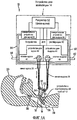
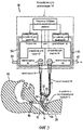
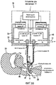
На Фиг. 1A представлено частичное схематическое изображение варианта осуществления аппарата для вентиляции согласно одному аспекту изобретения, аппарат показан контролируемо связанным с пациентом со стрелками, указывающими направление потока газа, когда клапаны и регулятор находятся в фазе ингаляции.In FIG. 1A is a partial schematic view of an embodiment of a ventilating apparatus according to one aspect of the invention, the apparatus is shown in a controllably connected manner to the patient with arrows indicating the direction of gas flow when the valves and regulator are in the inhalation phase.
На Фиг. 1B представлено изображение, подобное 1A, но показывающее частично закрытый клапан выдоха.In FIG. 1B is a view similar to 1A, but showing a partially closed exhalation valve.
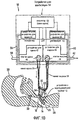
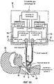
На Фиг. 2A представлено частичное схематическое изображение варианта осуществления Фиг. 1A, но стрелки показывают направление потока, когда клапаны и регулятор находятся в фазе выдоха режима разговора.In FIG. 2A is a partial schematic illustration of an embodiment of FIG. 1A, but the arrows show the flow direction when the valves and regulator are in the expiratory phase of the talk mode.
На Фиг. 2B представлено изображение, подобное 2A, но показывающее частично закрытый клапан выдоха и частично закрытый клапан вдоха.In FIG. 2B is a view similar to 2A, but showing a partially closed exhalation valve and a partially closed inspiratory valve.
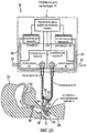
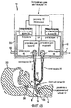
На Фиг. 3 представлено частичное схематическое изображение варианта осуществления Фиг. 1A, но стрелки показывают направление потока, когда клапаны и регулятор находятся в фазе выдоха в неразговорном режиме.In FIG. 3 is a partial schematic illustration of an embodiment of FIG. 1A, but the arrows show the direction of flow when the valves and regulator are in the expiratory phase in non-talking mode.
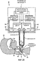
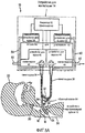
На Фиг. 4A представлен другой вариант осуществления настоящего изобретения, в котором эндотрахеальная трубка, вместо того, чтобы быть без обратного клапана, как на Фиг. 1A, имеет обратный клапан на ее открытом конце.In FIG. 4A shows another embodiment of the present invention in which the endotracheal tube, instead of being without a check valve, as in FIG. 1A has a check valve at its open end.
На Фиг. 4B представлено изображение, подобное 4A, но показывающее частично закрытый клапан выдоха.In FIG. 4B is a view similar to 4A, but showing a partially closed exhalation valve.
На Фиг. 5A представлено изображение, подобное Фиг. 4A, но стрелки указывают направление потока, когда клапаны и регулятор находятся в фазе выдоха.In FIG. 5A is a view similar to FIG. 4A, but the arrows indicate the direction of flow when the valves and regulator are in the expiratory phase.
На Фиг. 5B представлено изображение, подобное Фиг. 5A, но на котором показаны частично закрытые клапаны выдоха и вдоха; иIn FIG. 5B is a view similar to FIG. 5A, but showing partially closed exhalation and inspiration valves; and
На Фиг. 6 представлено схематичное изображение системы Фиг. 1 и 2 в виде аналоговой электросхемы и показано положение, в котором клапан выдоха полностью закрыт во время фаз выдоха и вдоха.In FIG. 6 is a schematic illustration of the system of FIG. 1 and 2 in the form of an analog wiring diagram and shows the position in which the exhalation valve is completely closed during the exhalation and inspiration phases.
Теперь более подробно будут рассмотрены Фиг. 1A, 1B, 2A, 2B и 3 (или короче "Фиг. 1-3"), на которых представлены изображения аппарата для вентиляции, в основном имеющего обозначение 10, являющиеся вариантами осуществления принципов настоящего изобретения. Аппарат для вентиляции 10 включает, в основном, устройство с эндотрахеальной трубкой, в основном имеющее обозначение 12, и устройство для вентиляции, в основном имеющее обозначение 14.Now, Figs. 1A, 1B, 2A, 2B and 3 (or shorter than “Fig. 1-3”), which depict images of a ventilation apparatus, generally designated 10, which are embodiments of the principles of the present invention. The apparatus for
Устройство с эндотрахеальной трубкой 12 включает эндотрахеальную трубку 16, сконструированную, например, в соответствии с принципами, раскрытыми в патенте '356. Эндотрахеальная трубка 16 сконструирована и выполнена с возможностью установки в трахею 18 пациента 20, как показано на Фиг.1-3, таким образом, чтобы открытый наружный конец 22 был соответственно фиксирован в положении на наружной поверхности шеи пациента 24, а открытый внутренний конец 26 сообщался с дыхательными путями и легкими пациента 28 в положении ниже голосовых связок пациента 30.An endotracheal tube device 12 includes an
На Фиг. 1-3 показана эндотрахеальная трубка 18, лишенная обратного клапана, часто называемого разговорным клапаном, такого как раскрытого в патенте '356.In FIG. 1 to 3 show an
Устройство для вентиляции 14 включает устройство с трубкой, в основном имеющее обозначение 32, которое включает Y-образный соединительный элемент 34 и трубчатые части, формирующие канал вдоха 36 и канал выдоха 38, как будет описано ниже. Основание Y-образного соединительного элемента 34 связано с открытым наружным концом 22 эндотрахеальной трубки 16 так, чтобы эндотрахеальная трубка была лишена обратного клапана и сообщалась с устройством с трубкой 32 для прохождения газов в любом направлении.The device for ventilation 14 includes a device with a tube, basically having the
Одно ответвление Y-образного соединительного элемента связано с трубкой или с участком трубки, образующей канал вдоха 36, а другое ответвление Y-образного соединительного элемента связано с трубкой или участком трубки, образующей канал выдоха 38. Как можно видеть на Фиг. 1-3, Y-образный соединительный элемент 34 служит для соединения канала вдоха 36 и канала выдоха 38 друг с другом.One branch of the Y-shaped connecting element is connected to the tube or to the portion of the tube forming the inspiration channel 36, and the other branch of the Y-shaped connecting element is connected to the tube or portion of the tube forming the exhalation channel 38. As can be seen in FIG. 1-3, a Y-shaped
Таким образом, описанное выше устройство с трубкой 32 расположено снаружи от устройства для вентиляции 14, как обозначено прерывистыми линиями на Фиг. 1-3. Устройство для вентиляции 14 включает устройство для респирации 40, которое включает устройство для вдоха 42 и устройство для выдоха 44. На Фиг. 1-3 устройство для вдоха 42 и устройство для выдоха 44 в устройстве для респирации 40 показаны схематично в виде столбиковой диаграммы. Компоненты для проведения потока газа, содержащиеся в устройствах для вдоха и выдоха 42 и 44 в устройстве для респирации 40, могут иметь обычную конфигурацию. Специфичное раскрытие одного варианта осуществления компонентов, используемых в соответствии с принципами настоящего изобретения, раскрыто в патенте '449.Thus, the above-described device with the
Как показано, устройство для вдоха 42 включает контролируемый клапан вдоха 46, который сообщается с каналом для вдоха 36, а устройство для выдоха 44 включает контролируемый клапан выдоха 48, который сообщается с каналом для выдоха 36.As shown, the inspiratory device 42 includes a controlled inspiratory valve 46, which communicates with the inspiratory channel 36, and the exhalation device 44 includes a controlled
Клапаны 46 и 48 предпочтительно контролируются электронным образом с помощью регулятора 52 и могут контролироваться таким образом, чтобы перемещаться от полностью закрытого до полностью открытого положения и любого положения между ними с частичным открытием. Клапаны 46 и 48 могут иметь любой подходящий тип для использования в устройстве для вентиляции, например, такой как клапан пропорционального соленоидального типа, или клапан управляемого шаговым электродвигателем типа.
Устройство для респирации 40 сконструировано и выполнено с возможностью его контроля, чтобы обеспечить повторяющиеся респираторные циклы. Каждый дыхательный цикл включает фазу вдоха, во время которой клапан вдоха 46 открыт, а клапан выдоха 48 закрыт. Во время каждой фазы вдоха устройство вдоха 42 контролируется с помощью регулятора 52, чтобы заставить поток газа проходить через открытый клапан вдоха 46, канал для вдоха 36, эндотрахеальную трубку 16 в дыхательные пути и легкие пациента 28. В одном варианте осуществления поток газа содержит воздух и кислород, смешанные с помощью устройства для вдоха 42 из воздуха, поступающего через входное отверстие 50 в устройстве вдоха 42, и кислорода, поступающего из устройства для вдоха 42. Однако можно использовать и присоединить через канал для вдоха 36 через клапан вдоха 46 любой известный источник газа.The respiratory device 40 is designed and configured to be controlled to provide repetitive respiratory cycles. Each respiratory cycle includes an inspiratory phase during which the inspiratory valve 46 is open and the
Каждый дыхательный цикл также включает фазу выдоха, во время которой клапан вдоха 46 закрыт или частично закрыт (то есть "относительно" закрыт, как будет описано ниже).Each respiratory cycle also includes an expiratory phase during which the inspiratory valve 46 is closed or partially closed (i.e., “relatively” closed, as will be described later).
Как лучше всего представлено на Фиг. 2A и 2B, в соответствии с вариантом осуществления изобретения клапан выдоха 48 контролируется с помощью регулятора 52 для удержания его в относительно закрытом положении, или для динамического контроля давления в устройстве с трубкой 32 в соответствии с желаемым профилем давления, во время фазы выдоха, с профилем давления, основанным на стремлении улучшить способность пациента говорить. Этот контроль клапана выдоха 48 позволяет во время фазы выдоха облегчить способность пациента говорить, даже при отсутствии обратного клапана, встроенного в эндотрахеальном устройстве 12 или устройстве с трубкой 32. Таким образом, во время фазы выдоха, когда пациент способен выдохнуть газ, поступивший в дыхательные пути и легкие в предыдущей фазе вдоха, относительно закрытые клапаны вдоха и выдоха 46 и 48 препятствуют прохождению газа через них, или контролируются таким образом, чтобы достигнуть такого профиля давления в устройстве с трубкой 32, чтобы выдыхаемый газ проходил через голосовые связки пациента 30 и выходил через ротовое отверстие пациента, таким образом облегчая способность пациента говорить, как показано стрелками на Фиг. 2A и 2B.As best shown in FIG. 2A and 2B, in accordance with an embodiment of the invention, the
Необходимо понимать, что в случаях, когда клапан вдоха или клапан выдоха описывается здесь как "закрытый" или "открытый", это не означает, что обязательно имеется в виду абсолютно или полностью открытый или полностью закрытый клапан (хотя это может иметь место), а скорее относительный открытый или закрытый клапан. Другими словами, например, когда клапан выдоха "закрыт", это не означает, что он полностью закрыт, чтобы препятствовать любому перемещению газа через него, как показано на Фиг. 1A и 2A. Скорее всего клапан выдоха может быть частично закрыт, но закрыт достаточно, чтобы достигнуть его желательных функциональных возможностей (как показано на Фиг. 1B и 2B). Таким образом, например, "относительно закрытый" или "относительно открытый" клапан выдоха означает относительно закрытую позицию и сравнительно относительно открытую позицию, соответственно, поскольку это относится конкретно к данному клапану. Подобным образом "закрытый" или "открытый" клапан вдоха относится к двум сравнительным позициям клапана вдоха, когда в одной позиции капан относительно закрыт или относительно открыт в сравнении с другой. Таким образом, используемый здесь термин "относительно закрытый" предназначен для передачи этого широкого понимания и значения.It should be understood that in cases where the inspiratory valve or the exhalation valve is described here as “closed” or “open”, this does not mean that a valve is absolutely or completely open or completely closed (although this may occur), but rather a relative open or closed valve. In other words, for example, when the exhalation valve is “closed”, this does not mean that it is completely closed to prevent any movement of gas through it, as shown in FIG. 1A and 2A. Most likely the exhalation valve can be partially closed, but closed enough to achieve its desired functionality (as shown in Fig. 1B and 2B). Thus, for example, a “relatively closed” or “relatively open” exhalation valve means a relatively closed position and a relatively relatively open position, respectively, since this applies specifically to this valve. Similarly, a “closed” or “open” inspiratory valve refers to two comparative positions of the inspiratory valve when, in one position, the trap is relatively closed or relatively open compared to the other. Thus, the term “relatively closed” as used herein is intended to convey this broad understanding and meaning.
Например, в фазе вдоха клапан выдоха не должен быть полностью закрыт, он может быть закрыт только до такой степени, при которой возможно достижение желательного давления в устройстве с трубкой 32 и легких пациента. Подобным образом, в фазе вдоха клапан вдоха не должен быть полностью открытым, но может быть открыт только до степени, достаточной для поступления необходимого количества газа в устройство с трубкой 32 и легкие пациента, для возможности пациента дышать (не показано). Подобным образом, в фазе выдоха клапан вдоха не должен быть полностью закрыт, но может быть частично закрыт (см. Фиг. 2B), а клапан выдоха должен быть закрыт только до степени, достаточной для поддержания желательного профиля давления в устройстве с трубкой 32 (см. Фиг. 2B).For example, in the inhalation phase, the exhalation valve should not be completely closed, it can only be closed to the extent that it is possible to achieve the desired pressure in the device with the
В одном варианте осуществления степень открытия и закрытия клапана выдоха и/или клапана вдоха динамически контролируется регулятором 52. В частности, для осуществления мониторинга давления, постоянно или периодически во время фазы вдоха и/или выдоха, и подачи сигнала к регулятору 52 для непрерывной или периодической подачи сигналов для открытия и/или закрытия клапана выдоха 48 и/или клапана вдоха до желательной степени можно использовать измерительное устройство для выдоха 58 и/или измерительное устройство для вдоха 54, основываясь на давлении, которое необходимо обеспечить в устройстве с трубкой 32, или желаемой скорости потока воздуха через связанный клапан 46 и/или 48 в любой момент дыхательного цикла, или основываясь на выборе разговорного или неразговорного режима работы. В одном варианте осуществления для определения степени открытия клапана и подачи сигналов обратной связи к регулятору 52 можно использовать кодирующее устройство или любой тип преобразователя.In one embodiment, the degree of opening and closing of the exhalation valve and / or inspiratory valve is dynamically controlled by the regulator 52. In particular, to monitor pressure continuously or periodically during the inspiratory and / or exhalation phase, and to provide a signal to the regulator 52 for continuous or intermittent signaling to open and / or close the
В одном варианте осуществления во время фазы вдоха клапан выдоха 48 относительно закрыт (то есть закрыт достаточно, чтобы позволить обеспечить пациента необходимым количеством газа, пригодного для дыхания), но может быть только частично закрыт для возможности прохождения лишнего газа (например приблизительно от 3 до 7 литров в минуту) через выходной порт 62 (см. Фиг. 1B). Кроме того, клапан вдоха 46 может быть полностью открыт или частично открыт, но в любом случае, относительно открыт при сравнении с тем, когда он находится в закрытом или относительно закрытом положении.In one embodiment, during the inspiratory phase, the
В одном варианте осуществления во время фазы выдоха клапан выдоха и клапан вдоха относительно закрыты, но один или оба клапана могут быть частично закрыты (см. Фиг. 2B) для контроля уровня или давления в устройстве с трубкой 32. Например, в одном варианте осуществления может быть желательно поддерживать давление в устройстве с трубкой 32 выше определенного порога, например, в одном варианте осуществления 5 сантиметров воды. Такой контроль часто называется позитивным и экспираторным давлением (PEEP), что можно использовать в настоящем изобретении, и как раскрыто в патенте США № 6823866, приведенном здесь в качестве ссылки в полном объеме. Этот способ можно использовать для поддержания давления в устройстве с трубкой 32 выше определенного уровня, для поддержания дыхательных путей пациента открытыми и/или улучшения способности пациента говорить.In one embodiment, during the expiratory phase, the exhalation valve and the inspiratory valve are relatively closed, but one or both valves may be partially closed (see Fig. 2B) to control the level or pressure in the device with the
Необходимо отметить, что, когда поток газов не проходит через сообщающие каналы вдоха и выдоха 36 и 38, когда клапаны 46 и 48 закрыты в фазе выдоха, связь, обеспечиваемая эндотрахеальной трубкой 16, состоит в том, что каналы 36 и 38 отражают давление в дыхательных путях во время фазы выдоха так же, как это происходит во время фазы вдоха.It should be noted that when the gas flow does not pass through the communicating channels of inhalation and exhalation 36 and 38, when the
В одном варианте осуществления регулятор 52 может являться программируемым микропроцессором и, как отмечено выше, предназначен для контроля работы устройства для респирации 40 для обеспечения повторных дыхательных циклов, включая контроль устройства для вдоха 42 и его клапана вдоха 46, и устройства для выдоха 44 и его клапана выдоха 48.In one embodiment, the controller 52 may be a programmable microprocessor and, as noted above, is designed to control the operation of the respiratory device 40 to ensure repeated breathing cycles, including monitoring the device for inspiration 42 and its inspiration valve 46, and exhalation device 44 and its
В регуляторе 52, в процессе контроля всей работы устройства для вентиляции 14, используются данные, связанные с измерением давления в дыхательных путях пациента, отражаемым в каналах вдоха и выдоха 36 и 38. Несмотря на то что результаты измерений могут быть получены от одного измерительного устройства, в показанном варианте осуществления предоставлены два измерительных устройства, включая измерительное устройство для вдоха 54, сообщающееся с каналом вдоха 36 посредством подходящей трубки 56, и отдельно измерительное устройство для выдоха 58, сообщающееся с каналом выдоха 38 посредством подходящей трубки 60. В одном варианте осуществления в измерительных устройствах 54 и 58 используются преобразователи давления, способные определять состояние давления в сообщающемся канале и преобразовывать определенное состояние давления в дискретный сигнал, который может быть получен и использован регулятором 52. Регулятор 52 открывает и закрывает клапаны 46 и 48, основываясь на данных измерительного устройства 54 и/или измерительного устройства 58, выходная информация от которых может использоваться для выявления фазы дыхания, в которой находится пациент. Таким образом, измерительные устройства отслеживают давление в легких пациента на протяжении всего дыхательного цикла для контроля открытия и закрытия клапанов 46 и 48.In the controller 52, in the process of monitoring the entire operation of the ventilation device 14, data related to the measurement of the pressure in the patient’s airways reflected in the inhalation and exhalation channels 36 and 38 are used. Although the measurement results can be obtained from one measuring device, in the embodiment shown, two measuring devices are provided, including a measuring device for inspiration 54 communicating with the inspiration channel 36 by means of a
В одном варианте осуществления в регуляторе используются два различных алгоритма, один для контроля клапана выдоха 48, а другой для контроля клапана вдоха 46. В другом варианте осуществления регулятор включает два отдельных блока контроля или модуля контроля, один из которых предназначен для контроля каждого клапана и связан по меньшей мере с одним из измерительных устройств 54 и 58.In one embodiment, the controller uses two different algorithms, one to control the
Из указанного выше необходимо понимать, что регулятор 52 запрограммирован так, чтобы во время каждой фазы выдоха запускался разговорный режим, при котором клапан выдоха остается закрытым или частично закрытым, как описано выше.From the above it is necessary to understand that the regulator 52 is programmed so that during each phase of exhalation, the conversational mode is started, in which the exhalation valve remains closed or partially closed, as described above.
Кроме того, регулятор запрограммирован так, чтобы во время фазы выдоха может быть включен неразговорный режим, при котором открыт клапан выдоха. В этом неразговорном режиме (или "первом" режиме) газ в дыхательных путях и легких пациента в конце фазы вдоха имеет возможность проходить через эндотрахеальную трубку 16, открытый клапан выдоха 48 и выходить через выходное отверстие 62, имеющееся в устройстве для выдоха 44, как показано стрелками на Фиг. 3. Фаза выдоха неразговорного режима включается, когда измерительное устройство 54 и/или 58 посылает сигнал регулятору 52, устанавливающему заданные условия. Например, если измерительное устройство 54 и/или 58 обнаруживает, что давление в устройстве с трубкой 32 не уменьшается с ожидаемой скоростью, это может служить признаком блокировки (например, газ нагнетается обратно в устройство с трубкой 32, а не проходит через голосовые связки) или окклюзии дыхательных путей. В этом случае, клапан выдоха 48 будет открыт для возможности выхода газа из легких пациента.In addition, the regulator is programmed so that during the exhalation phase a non-speaking mode can be activated in which the exhalation valve is open. In this non-speaking mode (or “first” mode), the gas in the patient’s airways and lungs at the end of the inspiratory phase is able to pass through the
Из указанного выше можно отметить, что аппарат для вентиляции 10, как описано выше, облегчает способность пациента говорить, во время разговорного режима (или "втором" режиме), как показано на Фиг. 2, а также предоставляет неразговорный режим вентиляции (см. Фиг. 3), просто посредством действия регулятора 52, как показано на Фиг. 3. Следует понимать, что некоторая способность говорить может иметь место в первом (или "неразговорном") режиме, хотя это может быть не столь благоприятно.From the above, it can be noted that the
Обратимся теперь конкретнее к Фиг. 4A, 4B, 5A и 5B (или короче, "Фиг. 4 и 5"), на которых показан альтернативный вариант осуществления. В этом варианте осуществления устройство с эндотрахеальной трубкой 12 включает обычный обратный клапан 64 в устройстве с трубкой 32. Этот вариант осуществления демонстрирует, что свойство обеспечивать возможность регулятору 52 выбирать режим, в котором клапан выдоха 48 удерживается в относительно закрытом положении, во время фазы выдоха, может обеспечить преимущества, даже когда используется обычный обратный клапан 64.Let us now turn more specifically to FIG. 4A, 4B, 5A and 5B (or shorter, “Figs. 4 and 5”) showing an alternative embodiment. In this embodiment, the device with endotracheal tube 12 includes a conventional check valve 64 in the device with
В варианте осуществления, представленном на Фиг. 4 и 5, регулятор 52 работает в разговорном режиме, подобном разговорному режиму, описанному выше. Отличие в том, что сообщение потока газа от пациента к устройству для вентиляции 14 во время фазы выдоха отключается обратным клапаном 64, а не относительно закрытым клапаном выдоха 48. Если регулятор 52 фактически функционирует для открытия выпускного клапана 48 во время фазы выдоха, как показано на Фиг. 3, в неразговорном режиме, то давление в канале выдоха 38 будет просто соответствовать атмосферному давлению во время фазы выдоха так, что измерительное устройство для выдоха 58 не будет осуществлять мониторинг давления в дыхательных путях пациента во время фазы выдоха.In the embodiment of FIG. 4 and 5, the controller 52 operates in a talk mode similar to the talk mode described above. The difference is that the flow of gas from the patient to the ventilator 14 during the exhalation phase is turned off by the check valve 64 rather than the relatively
Необходимо отметить, что Фиг. 4B функционально соответствует 4A, но на ней показан частично закрытый клапан выдоха, тогда как Фиг. 5B функционально соответствует Фиг. 5A, но на ней показаны частично закрытые клапаны вдоха и выдоха.It should be noted that FIG. 4B functionally corresponds to 4A, but it shows a partially closed exhalation valve, while FIG. 5B functionally corresponds to FIG. 5A, but it shows partially closed inspiratory and expiratory valves.
Как отмечено выше, регулятор 52 регулирует клапан выдоха 48 так, чтобы он был относительно закрытым во время фазы выдоха, когда клапан вдоха 46 относительно закрыт, и давление в канале выдоха 38 будет в основном равным давлению в дыхательных путях пациента во время всей фазы выдоха. При снижении давления в дыхательных путях пациента во время фазы выдоха измерительное устройство для выдоха может во время фазы выдоха продолжать осуществлять мониторинг снижения давления в дыхательных путях пациента. Поскольку закрытый (или частично закрытый) клапан вдоха 46 и закрытый (или частично закрытый) клапан выдоха 48 поддерживают давление в пределах соединительного канала вдоха 36 и канала выдоха 38 на уровне или несколько выше давления в легких пациента во время фазы выдоха, и поскольку это давление приблизительно сбалансировано с давлением в легких пациента посредством действия обратного клапана 64, измерительное устройство для выдоха 58 (и/или регулятор вдоха 54) способно эффективно приближенно выравнивать давление в легких пациента каждый раз во время фазы выдоха. Следовательно, при снижении давления в дыхательных путях пациента во время фазы выдоха давление в соединительных каналах 36 и 38 продолжит приравниваться к давлению в дыхательных путях пациента во время фазы выдоха. Таким образом, измерительное устройство для выдоха 58 осуществляет мониторинг давления в дыхательных путях пациента во время фазы выдоха, а не атмосферное давление, как имело бы место в случае открытого клапана выдоха.As noted above, the regulator 52 adjusts the
На Фиг. 6 схематично показана система с Фиг. 1 и 2, в виде аналоговой принципиальной электросхемы.In FIG. 6 schematically shows the system of FIG. 1 and 2, in the form of an analog circuit diagram.
На Фиг. 6 различные компоненты системы, показанной на Фиг. 1 и 2, изображены в виде электрических символов, как известно в области техники, каждый из которых помечен описательным словом или описательной аббревиатурой. Описательные аббревиатуры следующие: Rvocal_cords относится к сопротивлению голосовых связок пациента. Rvocal_cords показано в виде вариабельного резистора, чтобы показать вариабельное сопротивление, создаваемое голосовыми связками (например, более высокие звуки создают большее сопротивление). Rairway относится к сопротивлению дыхательных путей пациента. Rtube относится к сопротивлению системы трубок пациента или сопротивлению трубки. Ctube относится к коэффициенту податливости системы трубок пациента или коэффициенту податливости трубки, который может быть определен как емкость, или объем трубки, поделенный на давление в трубке. Clung относится к коэффициенту податливости легких пациента. Pmus относится к давлению, создаваемому в легких пациента с помощью мускулатуры пациента, и показывается как переменное давление, создаваемое пациентом посредством действия мускулатуры пациента (например, диафрагмы пациента, межреберных мышц, грудных мышц и т.д.).In FIG. 6 various components of the system shown in FIG. 1 and 2, are depicted in the form of electrical symbols, as is known in the technical field, each of which is marked with a descriptive word or descriptive abbreviation. Descriptive abbreviations are as follows: Rvocal_cords refers to the resistance of the patient's vocal cords. Rvocal_cords is shown as a variable resistor to show the variable resistance created by the vocal cords (for example, higher sounds create more resistance). Rairway refers to patient airway resistance. RTube refers to the resistance of a patient's tube system or the resistance of a tube. Ctube refers to the compliance coefficient of the patient’s tube system or the ductility coefficient, which can be defined as the capacity or volume of the tube divided by the pressure in the tube. Clung refers to the patient's lung compliance ratio. Pmus refers to the pressure created in the patient’s lungs using the patient’s muscles, and is shown as the variable pressure created by the patient through the action of the patient’s muscles (for example, the diaphragm of the patient, intercostal muscles, pectoral muscles, etc.).
Префиксная буква Q относится к величине газового потока, доставляемого с помощью вентилятора (Q vent) или пациентом во время фазы выдоха (Q exhalation). Приставка Q также относится к величине газового потока, доставляемого (1) к трубке или системе трубок (Q tube), (2) к пациенту (Q_patient), (3) к легким пациента (Q lung) и (4) к голосовым связкам пациента (Q cords).The prefix letter Q refers to the amount of gas flow delivered by the ventilator (Q vent) or by the patient during the exhalation phase (Q exhalation). The prefix Q also refers to the amount of gas flow delivered (1) to the tube or tube system (Q tube), (2) to the patient (Q_patient), (3) to the patient's lungs (Q lung), and (4) to the patient’s vocal cords (Q cords).
Как показано на Фиг. 6, газовый поток доставляется с помощью вентилятора (Q_vent) во время фазы вдоха дыхательного цикла. Поскольку во время этой фазы клапан выдоха закрыт (то есть переключен из открытого положения), газ доставляется к пациенту (Qjpatient) в дополнение к системе трубок (Qjtube). Во время фазы вдоха поток через голосовые связки (Q cords), как правило, нулевой, поскольку голосовая щель пациента закрыта (обозначено открытым выключателем рядом с Q cords на Фиг. 6), таким образом газ (Q_Lung) доставляется в легкие пациента.As shown in FIG. 6, the gas stream is delivered by a fan (Q_vent) during the inspiratory phase of the respiratory cycle. Since during this phase the exhalation valve is closed (i.e., switched from the open position), gas is delivered to the patient (Qjpatient) in addition to the tube system (Qjtube). During the inspiration phase, the flow through the vocal cords (Q cords) is generally zero, since the patient’s glottis is closed (indicated by the open switch next to the Q cords in FIG. 6), so that gas (Q_Lung) is delivered to the patient’s lungs.
Однако необходимо понимать, что в некоторых случаях во время фазы вдоха газ, доставляемый вентилятором, может быть использован пациентом с целью разговора, и таким образом поток через голосовые связки не равен нулю.However, it must be understood that in some cases, during the inspiratory phase, the gas delivered by the ventilator can be used by the patient for the purpose of conversation, and thus the flow through the vocal cords is not equal to zero.
Необходимо понимать, что открытый выключатель на Фиг. 6, отмеченный как "Клапан выдоха", обозначает положение, при котором клапан выдоха полностью закрыт для обеих фаз выдоха и вдоха. Этот выключатель может быть заменен вариабельным резистором для отображения положения, при котором клапан выдоха может быть частично или относительно закрыт во время фаз вдоха и/или выдоха.It should be understood that the open switch in FIG. 6, marked as “Exhalation Valve”, indicates the position at which the exhalation valve is completely closed for both phases of exhalation and inhalation. This switch may be replaced by a variable resistor to indicate the position at which the exhalation valve may be partially or relatively closed during the inspiratory and / or expiratory phases.
В основном, в фазе выдоха дыхательного цикла способность говорить облегчается. Речь осуществляется посредством увеличения давления в легких с помощью силы тяги грудных мышц, а также активности мышц диафрагмы. Во время разговора направление Q Lung изменяется на противоположное и направляет пациента через голосовые связки. Модуляция голосовых связок (то есть вариация сопротивления голосовых связок) отвечает за колебания связок, что в результате приводит к образованию речи.Basically, in the expiratory phase of the respiratory cycle, the ability to speak is facilitated. Speech is carried out by increasing pressure in the lungs using the traction force of the pectoral muscles, as well as the activity of the muscles of the diaphragm. During a conversation, the direction of Q Lung reverses and directs the patient through the vocal cords. Modulation of the vocal cords (that is, a variation in the resistance of the vocal cords) is responsible for the vibrations of the cords, resulting in the formation of speech.
Во время фазы выдоха клапан выдоха вентилятора остается закрытым (или частично закрытым), и таким образом, во время разговора большая часть газового потока перенаправляется на голосовые связки. Во время выдоха небольшое количество газа может поступать к коэффициенту податливости системы трубок. Этот коэффициент податливости обычно составляет менее 2 мл/см H2O, что мало в сравнении с коэффициентом податливости легких пациента (Clung), используя несколько миллилитров газового объема, выдыхаемого пациентом.During the expiratory phase, the exhalation valve of the fan remains closed (or partially closed), and thus, during the conversation, most of the gas flow is redirected to the vocal cords. During exhalation, a small amount of gas may flow to the ductility coefficient of the tube system. This compliance coefficient is usually less than 2 ml / cm H 2 O, which is small compared to the patient’s lung compliance coefficient (Clung) using a few milliliters of gas exhaled by the patient.
Варианты осуществления, описанные здесь без разговорного клапана (обратный клапан), имеют несколько преимуществ, включая, но не ограничиваясь ими, следующие:The embodiments described herein without a talk valve (non-return valve) have several advantages, including, but not limited to, the following:
1) Позволяют распознать раздутую манжету трахеотомической трубки. Это возможно вследствие того, что сенсоры давления вентилятора способны осуществлять мониторинг давления в системе трубок, и это давление, в свою очередь, отражает давление в дыхательных путях и легких пациента.1) Allow to recognize the inflated cuff of the tracheotomy tube. This is possible due to the fact that the fan pressure sensors are able to monitor the pressure in the tube system, and this pressure, in turn, reflects the pressure in the airways and lungs of the patient.
2) Позволяют оценить давление в дыхательных путях пациента во время выдоха так, чтобы избежать суммирования дыхательных движений. Это не осуществимо в вариантах осуществления, где используется разговорный клапан, так как клапан блокирует пневматическую связь с преобразователями давления вентилятора.2) Allow you to evaluate the pressure in the patient’s airways during exhalation so as to avoid the accumulation of respiratory movements. This is not feasible in embodiments where a talk valve is used, since the valve blocks pneumatic communication with the fan pressure transducers.
3) Учитывает сильный кашель пациента без препятствия со стороны мембраны одноходового клапана, так никакой клапан не используется.3) Considers a strong cough of the patient without obstruction from the membrane of the one-way valve, so no valve is used.
4) Позволяет осуществлять введение аэрозольных лекарственных средств без необходимости удаления разговорного клапана.4) Allows the administration of aerosol drugs without the need to remove the colloquial valve.
5) Позволяет осуществлять аспирацию без необходимости удаления разговорного клапана.5) Allows to carry out aspiration without the need to remove the colloquial valve.
6) Позволяет избежать необходимости удаления разговорного клапана для предотвращения засорения слюной диска/мембраны клапана, так как не требуется никакого разговорного клапана.6) Avoids the need to remove the colloquial valve to prevent clogging of the saliva of the valve disc / membrane, since no colloidal valve is required.
7) Необходимо отметить, что в вариантах осуществления, в которых присутствует разговорный клапан, объем газа, улавливаемого в систему трубок, может выходить только через разговорный клапан. Прохождение газа через разговорный клапан возможно только, если существует дифференциал давления на противоположной стороне клапана. Таким образом, мониторинг давления в дыхательных путях и легких пациента посредством мониторинга давления в системе трубок возможен, пока давление в устройстве с трубкой 32 превышает или соответствует давлению в легких пациента, что является способом работы настоящего изобретения.7) It should be noted that in the embodiments in which the talk valve is present, the volume of gas trapped in the tube system can only exit through the talk valve. The passage of gas through the talk valve is only possible if there is a differential pressure on the opposite side of the valve. Thus, monitoring the pressure in the patient’s airways and lungs by monitoring the pressure in the tube system is possible as long as the pressure in the device with the
Несмотря на то что изобретение было описано подробно с целью иллюстрации, на основании современных представлений о наиболее практичных и предпочтительных вариантах осуществления, необходимо понимать, что такие подробности предназначены исключительно для этой цели и что изобретение не ограничивается раскрытыми вариантами осуществления, но, напротив, предполагается, что оно охватывает модификации и эквивалентные конфигурации, которые охватываются сущностью и объемом приложенной формулы изобретения. Например, необходимо понимать, что настоящее изобретение предусматривает, до максимально возможной степени, что одно или более свойств любого варианта осуществления могут быть объединены с одним или более свойствами любого другого варианта осуществления.Despite the fact that the invention has been described in detail for the purpose of illustration, based on current ideas about the most practical and preferred embodiments, it should be understood that such details are intended solely for this purpose and that the invention is not limited to the disclosed embodiments, but, on the contrary, it is assumed that it encompasses modifications and equivalent configurations that are encompassed by the spirit and scope of the appended claims. For example, it is to be understood that the present invention provides, to the extent possible, that one or more of the properties of any embodiment can be combined with one or more properties of any other embodiment.
Claims (25)
(1) фазу вдоха, во время которой (а) пропорционально контролируемый клапан вдоха (46), сообщающийся с каналом вдоха (36), относительно открыт для прохождения газа через него в канал вдоха и к пациенту, и (b) пропорционально контролируемый клапан выдоха (48) между каналом выдоха (38) и выходным отверстием для выдоха (62) в устройстве для вентиляции относительно закрыт, и
(2) фазу выдоха, имеющую разговорный режим, во время которой пропорционально контролируемый клапан вдоха относительно закрыт, ограничивая вдыхаемый газ от пациента и атмосферы, и пропорционально контролируемый клапан выдоха относительно закрыт, и неразговорный режим, во время которого пропорционально контролируемый клапан вдоха относительно закрыт, ограничивая вдыхаемый газ от пациента и атмосферы, а пропорционально контролируемый клапан выдоха относительно открыт, где указанный способ включает в себя:
управление работой устройства для респирации посредством респираторных циклов при помощи контролирования пропорционально контролируемых клапанов вдоха и выдоха таким образом, что (а) во время фазы вдоха газ в канале вдоха протекает через эндотрахеальную трубку (16) и поступает в дыхательные пути и легкие пациента, при этом эндотрахеальная трубка вставлена ниже голосовых связок пациента, и (b) во время разговорного режима фазы выдоха пропорционально контролируемый клапан выдоха удерживается относительно закрытым, и пациент имеет возможность выдыхать газы из дыхательных путей и легких пациента, вокруг эндотрахеальной трубки мимо голосовых связок пациента и выходом из рта пациента; и
осуществление мониторинга давления, по меньшей мере, в одном из каналов во время фаз вдоха и выдоха с целью определения давления внутри пациента для использования в работе устройства для вентиляции посредством управления, по меньшей мере, одним из пропорционально контролируемых клапанов вдоха и выдоха для того, чтобы регулировать желаемое давление в, по меньшей мере, одном из каналов и пациенте во время обеих фаз.1. The method of operation of the device for ventilation (10), which includes a tube equipped with channels (12) of inhalation and exhalation, communicating with each other, and a device for respiration (40), configured to carry out respiratory cycles, which include :
(1) the inspiratory phase during which (a) the proportionally controlled inspiratory valve (46) communicating with the inspiratory channel (36) is relatively open for gas to pass through it into the inspiratory channel and to the patient, and (b) the proportionally controlled exhalation valve (48) between the exhalation channel (38) and the exhalation outlet (62) in the ventilation device is relatively closed, and
(2) an expiratory phase having a colloquial mode during which the proportionally controlled inspiratory valve is relatively closed, restricting the inhaled gas from the patient and the atmosphere, and the proportionally controlled exhalation valve is relatively closed, and a non-conversational mode during which the proportionally controlled inspiratory valve is relatively closed, restricting the inhaled gas from the patient and the atmosphere, and the proportionally controlled exhalation valve is relatively open, where the specified method includes:
controlling the operation of the respiratory device through respiratory cycles by controlling proportionally controlled inspiratory and expiratory valves so that (a) during the inspiratory phase, gas in the inspiratory channel flows through the endotracheal tube (16) and enters the patient’s respiratory tract and lungs, while the endotracheal tube is inserted below the patient’s vocal cords, and (b) during the colloquial phase of the expiratory phase, the proportionally controlled expiratory valve is kept relatively closed and the patient is the ability to exhale gases from the patient’s respiratory tract and lungs, around the endotracheal tube past the patient’s vocal cords and out of the patient’s mouth; and
monitoring the pressure in at least one of the channels during the inspiratory and expiratory phases in order to determine the pressure inside the patient for use in the ventilation device by controlling at least one of the proportionally controlled inspiratory and expiratory valves so that adjust the desired pressure in at least one of the channels and the patient during both phases.
трубку для соединения с наружным открытым концом эндотрахеальной трубки, снабженной каналами вдоха и выдоха (36, 38), сообщающимися друг с другом;
пропорционально контролируемые клапаны вдоха и выдоха (46, 48) в каналах вдоха и выдоха соответственно; и
регулятор (52), выполненный с возможностью контроля пропорционально контролируемого клапана вдоха и клапана выдоха, чтобы обеспечить повторные респираторные циклы, каждый из которых включает фазу вдоха и фазу выдоха, причем во время фазы вдоха пропорционально контролируемый клапан вдоха относительно открыт, а пропорционально контролируемый клапан выдоха относительно закрыт, причем поток газа способен проходить через канал вдоха и эндотрахеальную трубку в дыхательные пути и легкие пациента, причем во время фазы выдоха пропорционально контролируемый клапан вдоха относительно закрыт, ограничивая вдыхаемый газ от пациента и атмосферы, причем регулятор выполнен с возможностью управления пропорционально контролируемым клапаном выдоха для использования в двух режимах фазы выдоха, включающих:
(1) первый режим, в котором пропорционально контролируемый клапан выдоха относительно открыт во время фазы выдоха, позволяя газу из дыхательных путей и легких пациента после предшествующей фазы вдоха проходить через относительно открытый пропорционально контролируемый клапан выдоха и выходить через выходное отверстие устройства для вентиляции, и
(2) второй разговорный режим, при котором пропорционально контролируемый клапан выдоха удерживается относительно закрытым, так что пациент вызывает поступление газа из дыхательных путей и легких пациента после предшествующей фазы вдоха мимо эндотрахеальной трубки и голосовых связок пациента и выход его из ротового отверстия пациента.12. A device for ventilating a patient (14) for connecting with an endotracheal tube (12), designed to be installed through the patient’s trachea below the patient’s vocal cords so that the external open end of the endotracheal tube is outside the patient and the internal open end of the endotracheal tube communicates with airways and lungs of the patient, including:
a tube for connecting to the external open end of the endotracheal tube provided with inspiration and expiration channels (36, 38) communicating with each other;
proportionally controlled inspiratory and expiratory valves (46, 48) in the inspiration and expiration channels, respectively; and
a regulator (52) configured to control a proportionally controlled inspiratory valve and an exhalation valve to provide repeated respiratory cycles, each of which includes an inspiratory phase and an exhalation phase, moreover, during the inspiratory phase, the proportionally controlled inspiratory valve is relatively open and the proportionally controlled exhalation valve relatively closed, and the gas stream is able to pass through the inspiration channel and endotracheal tube into the patient’s airways and lungs, and during the exhalation phase is proportional ontroliruemy inhalation valve relatively closed, limiting the gas inhaled by the patient and the atmosphere, wherein the controller is adapted to control proportionally controlled exhalation valve for use in the two modes of the expiratory phase, comprising:
(1) a first mode in which the proportionally controlled exhalation valve is relatively open during the exhalation phase, allowing gas from the patient’s airways and lungs after the previous inhalation phase to pass through the relatively open proportionally controlled exhalation valve and exit through the outlet of the ventilation device, and
(2) the second colloquial mode, in which the proportionally controlled exhalation valve is kept relatively closed, so that the patient causes gas to flow from the patient’s airways and lungs after the previous phase of inhalation past the patient’s endotracheal tube and vocal cords and out of the patient’s mouth.
эндотрахеальную трубку (16), сконструированную с возможностью ее установки в трахею пациента ниже голосовых связок пациента так, чтобы ее наружный открытый конец находился вне пациента, а ее внутренний открытый конец находился вне пациента, а ее внутренний открытый конец сообщался с дыхательными путями и легкими пациента;
трубку, соединенную с наружным открытым концом трубки и снабженную каналами вдоха и выдоха (36, 38), сообщающимися друг с другом;
устройство (40) для респирации, сконструированное с возможностью обеспечения повторных респираторных циклов, каждый из которых включает (a) фазу вдоха, во время которой пропорционально контролируемый клапан вдоха (46) в канале вдоха относительно открыт, а пропорционально контролируемый клапан выдоха (48) в канале выдоха относительно закрыт, и при которой поток газа может проходить через канал вдоха и эндотрахеальную трубку в дыхательные пути и легкие пациента и (b) фазу выдоха, имеющую разговорный режим, во время которой пропорционально контролируемый клапан вдоха относительно закрыт, ограничивая вдыхаемый газ от пациента и атмосферу, а пропорционально контролируемый клапан выдоха удерживается относительно закрытым, вызывая протекание газа в дыхательных путях и легких пациента после предшествующей фазы вдоха мимо эндотрахеальной трубки и голосовых связок пациента и выход его из ротового отверстия пациента;
обратный клапан (64), оперативно соединенный с эндотрахеальной трубкой, позволяющий пациенту в конце каждой фазы вдоха вызывать прохождение газа из дыхательных путей и легких пациента через голосовые связки пациента и выход его из ротового отверстия пациента, причем обратный клапан выполнен с возможностью улавливания давления в легких пациента в конце фазы вдоха, когда оба пропорционально контролируемых клапана вдоха и выдоха относительно закрыты, для, по существу, уравнивания давления в каналах в конце каждой фазы вдоха с давлением в дыхательных путях и легких пациента во время фазы выдоха;
регулятор (52), который контролирует работу пропорционально контролируемых клапанов вдоха и выдоха; и
по меньшей мере, одно устройство измерения давления (45, 58) для мониторинга давления в каналах вдоха и выдоха во время обеих фаз вдоха и выдоха, причем устройство для измерения давления оперативно связано с регулятором для обеспечения поступления входящих сигналов к регулятору, которые используются для контроля пропорционально контролируемых клапана вдоха и клапана выдоха, для получения желаемого давления в, по меньшей мере, одном из каналов и пациенте.23. The apparatus for ventilation of the patient (10), including:
an endotracheal tube (16) designed to fit into the patient’s trachea below the patient’s vocal cords so that its outer open end is outside the patient and its inner open end is outside the patient and its inner open end communicates with the patient’s airways and lungs ;
a tube connected to the outer open end of the tube and provided with inspiration and expiration channels (36, 38) communicating with each other;
respiratory device (40) designed to provide repeated respiratory cycles, each of which includes (a) the inspiratory phase, during which the proportionally controlled inspiratory valve (46) in the inspiratory channel is relatively open and the proportionally controlled exhalation valve (48) in the exhalation channel is relatively closed, and in which the gas flow can pass through the inspiration channel and the endotracheal tube into the patient’s airways and lungs and (b) the expiratory phase, which has a colloquial mode, during which it is proportional to the control the inhaled inspiratory valve is relatively closed, restricting the inhaled gas from the patient and the atmosphere, and the proportionally controlled exhalation valve is kept relatively closed, causing gas to flow in the patient’s airways and lungs after the previous phase of inspiration past the patient’s endotracheal tube and vocal cords and out of the patient’s mouth ;
a non-return valve (64), operatively connected to the endotracheal tube, allowing the patient at the end of each phase of inspiration to cause the passage of gas from the patient’s airways and lungs through the patient’s vocal cords and exit from the patient’s mouth, and the non-return valve is designed to capture pressure in the lungs at the end of the inspiratory phase, when both proportionally controlled inspiratory and expiratory valves are relatively closed, to essentially equalize the pressure in the channels at the end of each phase of inspiration with the pressure in the pathways and lungs of the patient during the expiratory phase;
a regulator (52) that controls the operation of proportionally controlled inspiratory and expiratory valves; and
at least one pressure measuring device (45, 58) for monitoring pressure in the channels of inspiration and expiration during both phases of inspiration and exhalation, the device for measuring pressure being operatively connected to the controller to provide incoming signals to the controller, which are used for monitoring proportionally controlled inspiratory valve and exhalation valve, to obtain the desired pressure in at least one of the channels and the patient.
трубку для связи с наружным открытым концом эндотрахеальной трубки и обеспечения сообщения друг с другом канала вдоха (36) и канала выдоха (38);
пропорционально контролируемый клапан вдоха (46), оперативно соединенный с каналом вдоха;
пропорционально контролируемый клапан выдоха (48), оперативно соединенный с каналом выдоха; и
регулятор (52) для контроля пропорционально контролируемого клапана вдоха и пропорционально контролируемого клапана выдоха, для обеспечения повторных респираторных циклов, каждый из которых включает фазу вдоха и фазу выдоха, в котором во время фазы вдоха пропорционально контролируемый клапан вдоха относительно открыт, а пропорционально контролируемый клапан выдоха относительно закрыт, причем поток газа способен проходить через канал вдоха и трубку в дыхательные пути и легкие пациента, причем регулятор контролирует пропорционально контролируемый клапан выдоха для использования в двух режимах фазы выдоха, включающих:
(1) первый режим, в котором пропорционально контролируемый клапан вдоха относительно закрыт, ограничивая вдыхаемый газ от пациента и атмосферы, и пропорционально контролируемый клапан выдоха относительно открыт во время фазы выдоха, позволяя газу из дыхательных путей и легких пациента после предшествующей фазы вдоха проходить через относительно открытый пропорционально контролируемый клапан выдоха и выходить через выходное отверстие устройства для вентиляции, и
(2) второй разговорный режим, в котором пропорционально контролируемый клапан вдоха относительно закрыт, ограничивая вдыхаемый газ от пациента и атмосферы, и пропорционально контролируемый клапан выдоха удерживается относительно закрытым, так что пациент вызывает прохождение газа из дыхательных путей и легких пациента после предшествующей фазы вдоха, чтобы протекать мимо эндотрахеальной трубки и голосовых связок пациента, и выход его из ротового отверстия пациента. 25. A device for ventilating a patient (10) for connecting to an endotracheal tube (16), designed to be installed through the patient’s trachea below the patient’s vocal cords so that the external open end of the tube is outside the patient and the internal open end of the tube communicates with the airways and the patient’s lungs, including:
a tube for communicating with the outer open end of the endotracheal tube and for communicating with each other the inspiration channel (36) and the exhalation channel (38);
proportionally controlled inspiration valve (46), operatively connected to the inspiration channel;
proportionally controlled exhalation valve (48), operatively connected to the exhalation channel; and
a regulator (52) to control the proportionally controlled inspiratory valve and the proportionally controlled exhalation valve, to ensure repeated respiratory cycles, each of which includes the inspiratory phase and the exhalation phase, in which during the inspiratory phase the proportionally controlled inspiratory valve is relatively open and the proportionally controlled exhalation valve relatively closed, and the gas flow is able to pass through the inspiration channel and the tube into the patient’s airways and lungs, and the regulator controls proportionally A controlled expiratory valve for use in two exhalation phase modes, including:
(1) a first mode in which the proportionally controlled inspiratory valve is relatively closed, restricting the inhaled gas from the patient and the atmosphere, and the proportionally controlled exhalation valve is relatively open during the exhalation phase, allowing gas from the patient’s respiratory tract and lungs to pass through the relatively open the proportionally controlled exhalation valve and exit through the outlet of the ventilation device, and
(2) a second colloquial mode in which the proportionally controlled inspiratory valve is relatively closed, restricting the inhaled gas from the patient and the atmosphere, and the proportionally controlled exhalation valve is kept relatively closed so that the patient causes gas to pass from the patient’s airways and lungs after the previous inspiratory phase, to flow past the patient’s endotracheal tube and vocal cords, and exit from the patient’s mouth.
Applications Claiming Priority (2)
| Application Number | Priority Date | Filing Date | Title |
|---|---|---|---|
| US11/518,816 US7997272B2 (en) | 2006-09-11 | 2006-09-11 | Ventilating apparatus and method enabling a patient to talk with or without a trachostomy tube check valve |
| US11/518,816 | 2006-09-11 |
Publications (2)
| Publication Number | Publication Date |
|---|---|
| RU2009113599A RU2009113599A (en) | 2010-10-20 |
| RU2455031C2 true RU2455031C2 (en) | 2012-07-10 |
Family
ID=39168329
Family Applications (2)
| Application Number | Title | Priority Date | Filing Date |
|---|---|---|---|
| RU2009113536/14A RU2455030C2 (en) | 2006-09-11 | 2007-09-07 | Talk-mode deviation detection in artificial pulmonary ventilation system |
| RU2009113599/14A RU2455031C2 (en) | 2006-09-11 | 2007-09-07 | Ventilation apparatus and method enabling ability to speak with or without back-flow valve of tracheostomy tube |
Family Applications Before (1)
| Application Number | Title | Priority Date | Filing Date |
|---|---|---|---|
| RU2009113536/14A RU2455030C2 (en) | 2006-09-11 | 2007-09-07 | Talk-mode deviation detection in artificial pulmonary ventilation system |
Country Status (7)
| Country | Link |
|---|---|
| US (3) | US7997272B2 (en) |
| EP (2) | EP2066384B1 (en) |
| JP (2) | JP5184534B2 (en) |
| CN (2) | CN101553268B (en) |
| BR (2) | BRPI0716568A2 (en) |
| RU (2) | RU2455030C2 (en) |
| WO (1) | WO2008033732A2 (en) |
Cited By (1)
| Publication number | Priority date | Publication date | Assignee | Title |
|---|---|---|---|---|
| CN106492317A (en) * | 2016-11-25 | 2017-03-15 | 钟春兰 | A kind of medical atomized doser |
Families Citing this family (108)
| Publication number | Priority date | Publication date | Assignee | Title |
|---|---|---|---|---|
| US7588033B2 (en) | 2003-06-18 | 2009-09-15 | Breathe Technologies, Inc. | Methods, systems and devices for improving ventilation in a lung area |
| FR2858236B1 (en) * | 2003-07-29 | 2006-04-28 | Airox | DEVICE AND METHOD FOR SUPPLYING RESPIRATORY GAS IN PRESSURE OR VOLUME |
| AU2004266693B2 (en) | 2003-08-18 | 2011-03-10 | Breathe Technologies, Inc | Method and device for non-invasive ventilation with nasal interface |
| US11883029B2 (en) | 2005-01-20 | 2024-01-30 | Pulmonx Corporation | Methods and devices for passive residual lung volume reduction and functional lung volume expansion |
| US8496006B2 (en) | 2005-01-20 | 2013-07-30 | Pulmonx Corporation | Methods and devices for passive residual lung volume reduction and functional lung volume expansion |
| US20080228137A1 (en) | 2007-03-12 | 2008-09-18 | Pulmonx | Methods and devices for passive residual lung volume reduction and functional lung volume expansion |
| CN101454041B (en) | 2005-09-20 | 2012-12-12 | 呼吸科技公司 | Systems, methods and apparatus for respiratory support of a patient |
| US8518024B2 (en) | 2006-04-24 | 2013-08-27 | Transenterix, Inc. | System and method for multi-instrument surgical access using a single access port |
| EP2023987B1 (en) | 2006-05-18 | 2016-11-09 | Breathe Technologies, Inc. | Tracheotomy device |
| EP2068992B1 (en) | 2006-08-03 | 2016-10-05 | Breathe Technologies, Inc. | Devices for minimally invasive respiratory support |
| US7997272B2 (en) * | 2006-09-11 | 2011-08-16 | Ric Investments, Llc. | Ventilating apparatus and method enabling a patient to talk with or without a trachostomy tube check valve |
| WO2008144589A1 (en) | 2007-05-18 | 2008-11-27 | Breathe Technologies, Inc. | Methods and devices for sensing respiration and providing ventilation therapy |
| EP2200686A4 (en) | 2007-09-26 | 2017-11-01 | Breathe Technologies, Inc. | Methods and devices for providing inspiratory and expiratory flow relief during ventilation therapy |
| CN101888868B (en) | 2007-09-26 | 2014-01-22 | 呼吸科技公司 | Methods and devices for treating sleep apnea |
| US9199049B2 (en) * | 2007-10-24 | 2015-12-01 | Jeffrey A Attwood | Expiratory volume reservoir for a ventilator patient circuit |
| CN101468219B (en) * | 2007-12-28 | 2012-10-31 | 北京谊安医疗系统股份有限公司 | Gas path system and operation method thereof as well as breathing apparatus and anesthesia apparatus using the system |
| EP2276535B1 (en) | 2008-04-18 | 2020-05-27 | Breathe Technologies, Inc. | Devices for sensing respiration and controlling ventilator functions |
| WO2009129506A1 (en) | 2008-04-18 | 2009-10-22 | Breathe Technologies, Inc. | Methods and devices for sensing respiration and controlling ventilator functions |
| US8251876B2 (en) | 2008-04-22 | 2012-08-28 | Hill-Rom Services, Inc. | Breathing exercise apparatus |
| US8752546B2 (en) * | 2008-04-23 | 2014-06-17 | General Electric Company | System and method for mobilizing occlusions from a breathing tube |
| US8457706B2 (en) * | 2008-05-16 | 2013-06-04 | Covidien Lp | Estimation of a physiological parameter using a neural network |
| US8925549B2 (en) * | 2008-08-11 | 2015-01-06 | Surge Ingenuity Corporation | Flow control adapter for performing spirometry and pulmonary function testing |
| CN102196837B (en) | 2008-08-22 | 2015-09-09 | 呼吸科技公司 | Open air flue interface is utilized to provide the method and apparatus of mechanical ventilation |
| US8302602B2 (en) | 2008-09-30 | 2012-11-06 | Nellcor Puritan Bennett Llc | Breathing assistance system with multiple pressure sensors |
| EP2344791B1 (en) | 2008-10-01 | 2016-05-18 | Breathe Technologies, Inc. | Ventilator with biofeedback monitoring and control for improving patient activity and health |
| US9675774B2 (en) * | 2009-04-02 | 2017-06-13 | Breathe Technologies, Inc. | Methods, systems and devices for non-invasive open ventilation with gas delivery nozzles in free space |
| US9132250B2 (en) | 2009-09-03 | 2015-09-15 | Breathe Technologies, Inc. | Methods, systems and devices for non-invasive ventilation including a non-sealing ventilation interface with an entrainment port and/or pressure feature |
| US20100218766A1 (en) * | 2009-02-27 | 2010-09-02 | Nellcor Puritan Bennett Llc | Customizable mandatory/spontaneous closed loop mode selection |
| US8434479B2 (en) * | 2009-02-27 | 2013-05-07 | Covidien Lp | Flow rate compensation for transient thermal response of hot-wire anemometers |
| US9962512B2 (en) | 2009-04-02 | 2018-05-08 | Breathe Technologies, Inc. | Methods, systems and devices for non-invasive ventilation including a non-sealing ventilation interface with a free space nozzle feature |
| FR2945217B1 (en) * | 2009-05-07 | 2012-09-21 | Assist Publ Hopitaux De Paris | PHONATION ASSISTANCE DEVICE FOR A TRACHEOTOMISED PATIENT. |
| CA2774902C (en) | 2009-09-03 | 2017-01-03 | Breathe Technologies, Inc. | Methods, systems and devices for non-invasive ventilation including a non-sealing ventilation interface with an entrainment port and/or pressure feature |
| US8469031B2 (en) | 2009-12-01 | 2013-06-25 | Covidien Lp | Exhalation valve assembly with integrated filter |
| US8439036B2 (en) | 2009-12-01 | 2013-05-14 | Covidien Lp | Exhalation valve assembly with integral flow sensor |
| US20110126832A1 (en) * | 2009-12-01 | 2011-06-02 | Nellcor Puritan Bennett Llc | Exhalation Valve Assembly |
| US8439037B2 (en) * | 2009-12-01 | 2013-05-14 | Covidien Lp | Exhalation valve assembly with integrated filter and flow sensor |
| US8469030B2 (en) | 2009-12-01 | 2013-06-25 | Covidien Lp | Exhalation valve assembly with selectable contagious/non-contagious latch |
| WO2011086435A2 (en) * | 2010-01-14 | 2011-07-21 | Koninklijke Philips Electronics N.V. | Servo ventilation using negative pressure support |
| USD653749S1 (en) | 2010-04-27 | 2012-02-07 | Nellcor Puritan Bennett Llc | Exhalation module filter body |
| USD655809S1 (en) | 2010-04-27 | 2012-03-13 | Nellcor Puritan Bennett Llc | Valve body with integral flow meter for an exhalation module |
| USD655405S1 (en) | 2010-04-27 | 2012-03-06 | Nellcor Puritan Bennett Llc | Filter and valve body for an exhalation module |
| CN102946933B (en) * | 2010-06-22 | 2016-09-14 | 皇家飞利浦电子股份有限公司 | Respiratory interface device |
| US9968750B2 (en) * | 2010-06-30 | 2018-05-15 | St. Michael's Hospital | Method and system for patient-synchronized ventilatory assist with endotracheal through-flow |
| CN103096981B (en) | 2010-08-16 | 2015-07-22 | 呼吸科技公司 | Methods, systems and devices using lox to provide ventilatory support |
| US9370633B2 (en) | 2010-09-10 | 2016-06-21 | Carefusion 207, Inc. | Nasal intermittent mandatory ventilation (NIMV) control system in a ventilator |
| CA3027061C (en) | 2010-09-30 | 2020-12-01 | Breathe Technologies, Inc. | Methods, systems and devices for humidifying a respiratory tract |
| BR112013015386B1 (en) * | 2010-12-21 | 2020-12-01 | Koninklijke Philips N.V. | system for controlling the expiratory air flow of a machine-induced patient |
| US9629971B2 (en) | 2011-04-29 | 2017-04-25 | Covidien Lp | Methods and systems for exhalation control and trajectory optimization |
| US20120272962A1 (en) * | 2011-04-29 | 2012-11-01 | Nellcor Puritan Bennett Llc | Methods and systems for managing a ventilator patient with a capnometer |
| JP6329902B2 (en) * | 2011-09-13 | 2018-05-23 | レスメド・リミテッドResMed Limited | Respirator vent device |
| US9364624B2 (en) | 2011-12-07 | 2016-06-14 | Covidien Lp | Methods and systems for adaptive base flow |
| US9498589B2 (en) | 2011-12-31 | 2016-11-22 | Covidien Lp | Methods and systems for adaptive base flow and leak compensation |
| US9022031B2 (en) | 2012-01-31 | 2015-05-05 | Covidien Lp | Using estimated carinal pressure for feedback control of carinal pressure during ventilation |
| US9180271B2 (en) | 2012-03-05 | 2015-11-10 | Hill-Rom Services Pte. Ltd. | Respiratory therapy device having standard and oscillatory PEP with nebulizer |
| US9327089B2 (en) | 2012-03-30 | 2016-05-03 | Covidien Lp | Methods and systems for compensation of tubing related loss effects |
| US8844526B2 (en) | 2012-03-30 | 2014-09-30 | Covidien Lp | Methods and systems for triggering with unknown base flow |
| US9144658B2 (en) | 2012-04-30 | 2015-09-29 | Covidien Lp | Minimizing imposed expiratory resistance of mechanical ventilator by optimizing exhalation valve control |
| AU2013304950B2 (en) * | 2012-08-22 | 2016-11-03 | Resmed Paris Sas | Breathing assistance system with speech detection |
| US10076619B2 (en) | 2012-09-11 | 2018-09-18 | Resmed Limited | Vent arrangement for respiratory mask |
| GB201222684D0 (en) * | 2012-12-15 | 2013-01-30 | Smiths Medical Int Ltd | Medico-surgical apparatus |
| US9492629B2 (en) | 2013-02-14 | 2016-11-15 | Covidien Lp | Methods and systems for ventilation with unknown exhalation flow and exhalation pressure |
| USD731049S1 (en) | 2013-03-05 | 2015-06-02 | Covidien Lp | EVQ housing of an exhalation module |
| USD744095S1 (en) | 2013-03-08 | 2015-11-24 | Covidien Lp | Exhalation module EVQ internal flow sensor |
| USD736905S1 (en) | 2013-03-08 | 2015-08-18 | Covidien Lp | Exhalation module EVQ housing |
| USD693001S1 (en) | 2013-03-08 | 2013-11-05 | Covidien Lp | Neonate expiratory filter assembly of an exhalation module |
| DE102013004115A1 (en) * | 2013-03-08 | 2014-09-11 | Universitätsmedizin Der Johannes Gutenberg-Universität Mainz | TRACHEAL CANNULA AND SPEAKING VENTILATION SYSTEM FOR MACHINE VENTILATION |
| USD701601S1 (en) | 2013-03-08 | 2014-03-25 | Covidien Lp | Condensate vial of an exhalation module |
| USD692556S1 (en) | 2013-03-08 | 2013-10-29 | Covidien Lp | Expiratory filter body of an exhalation module |
| USD731048S1 (en) | 2013-03-08 | 2015-06-02 | Covidien Lp | EVQ diaphragm of an exhalation module |
| USD731065S1 (en) | 2013-03-08 | 2015-06-02 | Covidien Lp | EVQ pressure sensor filter of an exhalation module |
| US9981096B2 (en) | 2013-03-13 | 2018-05-29 | Covidien Lp | Methods and systems for triggering with unknown inspiratory flow |
| US9950135B2 (en) | 2013-03-15 | 2018-04-24 | Covidien Lp | Maintaining an exhalation valve sensor assembly |
| US9839761B1 (en) | 2013-07-04 | 2017-12-12 | Hal Rucker | Airflow control for pressurized air delivery |
| US9440039B2 (en) | 2013-07-17 | 2016-09-13 | Upods, Llc | Gas delivery device |
| US9925348B2 (en) | 2013-07-17 | 2018-03-27 | Upods, Llc | Gas delivery device |
| DE202014000155U1 (en) * | 2013-12-24 | 2015-03-26 | Ac Aircontrols Gmbh | System for providing a gas for the ventilation of a patient |
| WO2015095969A1 (en) * | 2013-12-27 | 2015-07-02 | St. Michael's Hospital | Device, method and system for providing ventilatory assist to a patient |
| US9757532B2 (en) * | 2014-02-14 | 2017-09-12 | Breathe Technologies, Inc. | Detection of patient interface disconnect for controlling continuous positive airway pressure therapy |
| US9808591B2 (en) | 2014-08-15 | 2017-11-07 | Covidien Lp | Methods and systems for breath delivery synchronization |
| US11285287B2 (en) | 2014-09-30 | 2022-03-29 | Frank H. Arlinghaus, Jr. | Tracheostomy or endotracheal tube adapter for speech |
| WO2016053574A1 (en) | 2014-09-30 | 2016-04-07 | Arlinghaus Jr Frank H | A tracheostomy or endotracheal tube adapter for speech |
| US9950129B2 (en) | 2014-10-27 | 2018-04-24 | Covidien Lp | Ventilation triggering using change-point detection |
| US10786645B2 (en) * | 2014-12-30 | 2020-09-29 | Koninklijke Philips N.V. | Capnometry system with supplemental oxygen detection and method of operation thereof |
| US9925346B2 (en) | 2015-01-20 | 2018-03-27 | Covidien Lp | Systems and methods for ventilation with unknown exhalation flow |
| EP4186548A1 (en) | 2015-04-02 | 2023-05-31 | Hill-Rom Services PTE. LTD. | Mask leakage detection for a respiratory device |
| USD775345S1 (en) | 2015-04-10 | 2016-12-27 | Covidien Lp | Ventilator console |
| GB2540024A (en) * | 2015-06-11 | 2017-01-04 | Smiths Medical Int Ltd | Ventilator systems and controls |
| US10765822B2 (en) | 2016-04-18 | 2020-09-08 | Covidien Lp | Endotracheal tube extubation detection |
| DE112018000912A5 (en) * | 2017-02-20 | 2019-10-24 | Weinmann Emergency Medical Technology Gmbh + Co. Kg | Method and device for ventilation |
| CN107569753B (en) * | 2017-08-22 | 2021-02-19 | 天津怡和嘉业医疗科技有限公司 | Breathing pipeline, breathing machine and sensor data transmission method |
| US10792449B2 (en) | 2017-10-03 | 2020-10-06 | Breathe Technologies, Inc. | Patient interface with integrated jet pump |
| DE102017009603A1 (en) * | 2017-10-13 | 2019-04-18 | Drägerwerk AG & Co. KGaA | Device for ventilating a patient |
| CN109939311A (en) * | 2017-12-20 | 2019-06-28 | 北京谊安医疗系统股份有限公司 | The judgment method and ventilator of breathing circuit obstruction block warning device |
| DE102018003026A1 (en) * | 2018-04-13 | 2019-10-17 | Drägerwerk AG & Co. KGaA | Ventilation device with a safety valve |
| CN109172986A (en) * | 2018-10-15 | 2019-01-11 | 福建中医药大学附属人民医院(福建省人民医院) | A kind of auxiliary sounding device and bionical vocal technique |
| CN109758153B (en) * | 2019-01-30 | 2024-04-02 | 上海长征医院 | Full nasal cavity air pressure detection equipment and application method thereof |
| GB2581999B (en) * | 2019-03-07 | 2023-01-04 | Bpr Medical Ltd | Gas flow alarm |
| US11324954B2 (en) | 2019-06-28 | 2022-05-10 | Covidien Lp | Achieving smooth breathing by modified bilateral phrenic nerve pacing |
| US20220288347A1 (en) * | 2019-08-16 | 2022-09-15 | Korea University Research And Business Foundation | Bidirectional Flow-Controllable Artificial Respirator |
| KR102470057B1 (en) * | 2019-08-16 | 2022-11-23 | 고려대학교 산학협력단 | bidirectional flow controllable ventilator |
| US11896767B2 (en) | 2020-03-20 | 2024-02-13 | Covidien Lp | Model-driven system integration in medical ventilators |
| CN111536277B (en) * | 2020-06-17 | 2022-04-08 | 中国建筑设计研究院有限公司 | Drainage non-return system and drainage non-return method |
| RU201954U1 (en) * | 2020-10-07 | 2021-01-22 | Общество с ограниченной ответственностью (ООО) "АЛЬТОНИКА" | Electronic monitoring and control device of artificial lung ventilation apparatus |
| RU201157U1 (en) * | 2020-10-27 | 2020-12-01 | Общество с ограниченной ответственностью (ООО) "АЛЬТОНИКА" | Electronic control and remote control device for artificial lung ventilation apparatus |
| WO2022133657A1 (en) * | 2020-12-21 | 2022-06-30 | 深圳麦科田生物医疗技术股份有限公司 | Breathing assembly supporting voice function and ventilation method thereof, and breathing machine |
| EP4129377A1 (en) * | 2021-08-07 | 2023-02-08 | Löwenstein Medical Technology S.A. | Ventilator system with speaking function |
| WO2023148794A1 (en) * | 2022-02-03 | 2023-08-10 | Universita' Degli Studi Di Firenze | Device for maintaining peep in a patient, and mechanical ventilation circuit comprising said device |
| WO2024052339A1 (en) * | 2022-09-07 | 2024-03-14 | Ben Fabry | Ventilator and method for controlling a ventilator |
Citations (3)
| Publication number | Priority date | Publication date | Assignee | Title |
|---|---|---|---|---|
| US4442856A (en) * | 1981-08-18 | 1984-04-17 | Puritan-Bennett | Oxygen regulator and alarm system for an anesthesia machine |
| GB2318518A (en) * | 1997-12-10 | 1998-04-29 | Falah Hasan Ali | Micro ventilation anaesthetic circuit |
| RU2144386C1 (en) * | 1994-06-04 | 2000-01-20 | Ян Джереми Брейн Арчибальд | Intubation air-duct device with laryngeal mask and fiber optics |
Family Cites Families (26)
| Publication number | Priority date | Publication date | Assignee | Title |
|---|---|---|---|---|
| US4219020A (en) * | 1978-08-09 | 1980-08-26 | Fraser Sweatman, Inc. | Scavenger valve attachment for inhalation sedation system mask |
| US4280492A (en) * | 1979-10-05 | 1981-07-28 | Latham Phillip B | Tracheostomy tube |
| US4538607A (en) * | 1984-02-06 | 1985-09-03 | Ab Fixfabriken | Tracheostomy valve |
| DE3422066A1 (en) * | 1984-06-14 | 1985-12-19 | Drägerwerk AG, 2400 Lübeck | VENTILATION SYSTEM AND CONTROLLABLE VALVE UNIT TO |
| WO1986005102A1 (en) * | 1985-03-08 | 1986-09-12 | Muir David A | Tracheostomy device |
| JPS61232842A (en) * | 1985-04-08 | 1986-10-17 | チエスト株式会社 | Sounding apparatus |
| US4593689A (en) * | 1985-04-15 | 1986-06-10 | White Kenneth S | Endotracheal tube including means for patient communication |
| US5813399A (en) * | 1993-03-16 | 1998-09-29 | Puritan Bennett Corporation | System and method for closed loop airway pressure control during the inspiratory cycle of a breath in a patient ventilator using the exhalation valve as a microcomputer-controlled relief valve |
| US5392775A (en) * | 1994-03-22 | 1995-02-28 | Adkins, Jr.; Claude N. | Duckbill valve for a tracheostomy tube that permits speech |
| US5881717A (en) * | 1997-03-14 | 1999-03-16 | Nellcor Puritan Bennett Incorporated | System and method for adjustable disconnection sensitivity for disconnection and occlusion detection in a patient ventilator |
| CA2303970C (en) * | 1997-09-19 | 2009-09-08 | Respironics, Inc. | Medical ventilator |
| US6722367B1 (en) * | 1997-12-22 | 2004-04-20 | Hansa Medical Products, Inc. | Valved fenestrated tracheotomy tube having outer and inner cannulae |
| US6189534B1 (en) * | 1998-10-13 | 2001-02-20 | Mallinckrodt Inc. | Bi-functional in-line phonation valve |
| US6230708B1 (en) * | 1998-10-30 | 2001-05-15 | Sechrist Industries, Inc. | Ventilator triggering device |
| US6334441B1 (en) * | 1998-11-23 | 2002-01-01 | Mallinckrodt Medical, Inc. | Phonation valve for breathing tube |
| ES2201578T3 (en) * | 1999-02-01 | 2004-03-16 | Adeva Medical Gesellschaft Fur Entwicklung Und Vertrieb Von Medizinischen Implantat-Artikeln Mbh | VALVE FOR A TRAQUOSTOMA. |
| US6401713B1 (en) * | 1999-05-05 | 2002-06-11 | Respironics, Inc. | Apparatus and method of providing continuous positive airway pressure |
| US6626175B2 (en) * | 2000-10-06 | 2003-09-30 | Respironics, Inc. | Medical ventilator triggering and cycling method and mechanism |
| US6588428B2 (en) * | 2001-02-23 | 2003-07-08 | Adam Spence Corp. | Speaking valve for a tracheostomy tube |
| US6725862B2 (en) * | 2001-08-24 | 2004-04-27 | Naum Klinberg | Tracheostomy tube apparatus for noninvasive suctioning |
| JP2003210585A (en) * | 2002-01-21 | 2003-07-29 | Hiroaki Nomori | Tracheotomic tube |
| AU2003297942B2 (en) * | 2002-12-16 | 2009-01-08 | Rutter, Dr Michael J. | Tracheotomy valve unit |
| US7905231B2 (en) | 2003-03-24 | 2011-03-15 | Resmed Paris | Breathing assistance apparatus |
| FR2852853B1 (en) * | 2003-03-24 | 2006-12-29 | Saime Sarl | DEVICE FOR AIDING BREATHING |
| US7617824B2 (en) * | 2005-12-08 | 2009-11-17 | Ric Investments, Llc | Ventilator adaptable for use with either a dual-limb circuit or a single-limb circuit |
| US7997272B2 (en) * | 2006-09-11 | 2011-08-16 | Ric Investments, Llc. | Ventilating apparatus and method enabling a patient to talk with or without a trachostomy tube check valve |
-
2006
- 2006-09-11 US US11/518,816 patent/US7997272B2/en active Active
-
2007
- 2007-08-17 US US11/893,796 patent/US8161972B2/en active Active
- 2007-09-07 BR BRPI0716568-4A patent/BRPI0716568A2/en not_active Application Discontinuation
- 2007-09-07 CN CN2007800335126A patent/CN101553268B/en active Active
- 2007-09-07 BR BRPI0716567-6A patent/BRPI0716567A2/en not_active IP Right Cessation
- 2007-09-07 JP JP2009527589A patent/JP5184534B2/en active Active
- 2007-09-07 EP EP07842073.4A patent/EP2066384B1/en active Active
- 2007-09-07 WO PCT/US2007/077906 patent/WO2008033732A2/en active Application Filing
- 2007-09-07 EP EP07842070.0A patent/EP2066412B1/en active Active
- 2007-09-07 JP JP2009527588A patent/JP5264733B2/en not_active Expired - Fee Related
- 2007-09-07 CN CN2007800335037A patent/CN101553284B/en active Active
- 2007-09-07 RU RU2009113536/14A patent/RU2455030C2/en active
- 2007-09-07 RU RU2009113599/14A patent/RU2455031C2/en active
-
2011
- 2011-07-01 US US13/174,859 patent/US20110259339A1/en not_active Abandoned
Patent Citations (3)
| Publication number | Priority date | Publication date | Assignee | Title |
|---|---|---|---|---|
| US4442856A (en) * | 1981-08-18 | 1984-04-17 | Puritan-Bennett | Oxygen regulator and alarm system for an anesthesia machine |
| RU2144386C1 (en) * | 1994-06-04 | 2000-01-20 | Ян Джереми Брейн Арчибальд | Intubation air-duct device with laryngeal mask and fiber optics |
| GB2318518A (en) * | 1997-12-10 | 1998-04-29 | Falah Hasan Ali | Micro ventilation anaesthetic circuit |
Cited By (2)
| Publication number | Priority date | Publication date | Assignee | Title |
|---|---|---|---|---|
| CN106492317A (en) * | 2016-11-25 | 2017-03-15 | 钟春兰 | A kind of medical atomized doser |
| CN106492317B (en) * | 2016-11-25 | 2019-06-14 | 钟春兰 | A kind of medical atomized drug delivery device |
Also Published As
| Publication number | Publication date |
|---|---|
| JP5184534B2 (en) | 2013-04-17 |
| US20080060646A1 (en) | 2008-03-13 |
| CN101553268B (en) | 2013-03-06 |
| JP2010502402A (en) | 2010-01-28 |
| EP2066384A2 (en) | 2009-06-10 |
| CN101553268A (en) | 2009-10-07 |
| WO2008033732A2 (en) | 2008-03-20 |
| CN101553284A (en) | 2009-10-07 |
| BRPI0716568A2 (en) | 2013-11-05 |
| EP2066384A4 (en) | 2014-11-05 |
| US8161972B2 (en) | 2012-04-24 |
| RU2009113536A (en) | 2010-10-20 |
| RU2455030C2 (en) | 2012-07-10 |
| RU2009113599A (en) | 2010-10-20 |
| EP2066412B1 (en) | 2016-11-16 |
| BRPI0716567A2 (en) | 2013-10-15 |
| JP5264733B2 (en) | 2013-08-14 |
| US20080060656A1 (en) | 2008-03-13 |
| EP2066412A4 (en) | 2014-11-05 |
| EP2066384B1 (en) | 2018-12-19 |
| EP2066412A2 (en) | 2009-06-10 |
| CN101553284B (en) | 2013-07-31 |
| US20110259339A1 (en) | 2011-10-27 |
| JP2010502401A (en) | 2010-01-28 |
| WO2008033732A3 (en) | 2008-06-12 |
| US7997272B2 (en) | 2011-08-16 |
Similar Documents
| Publication | Publication Date | Title |
|---|---|---|
| RU2455031C2 (en) | Ventilation apparatus and method enabling ability to speak with or without back-flow valve of tracheostomy tube | |
| JP2010502402A5 (en) | ||
| US6095140A (en) | Ventilator triggering device | |
| US9295795B2 (en) | System for providing flow-targeted ventilation synchronized to a patients breathing cycle | |
| JP2010502401A5 (en) | ||
| US20160256661A1 (en) | Improved oxygenating apparatus | |
| JPH09108353A (en) | Tracheal tube and device for artificial respiration apparatus | |
| CN102416213A (en) | Method and arrangement for respiratory support for a patient airway prosthesis and catheter | |
| WO2009052631A1 (en) | Ventilation stabilization system | |
| US8925549B2 (en) | Flow control adapter for performing spirometry and pulmonary function testing | |
| JP4439919B2 (en) | Breathing apparatus | |
| EP3921008B1 (en) | A valve actuation assembly and a system for controlling a supply of gas for inhalation by a user | |
| JP2003501159A (en) | Artificial respirator | |
| JP2001037881A (en) | High frequency respirator | |
| WO2008033730A2 (en) | Detecting ventilator system anomalies while in a speaking mode | |
| JP2994172B2 (en) | Breathing aid | |
| JP2023521584A (en) | Devices and systems for respiratory assistance | |
| JP2023521583A (en) | Devices and systems for respiratory assistance | |
| JP2005211273A (en) | Tube with cuff |