RU2445539C2 - Device to detect drive position - Google Patents
Device to detect drive position Download PDFInfo
- Publication number
- RU2445539C2 RU2445539C2 RU2009112050/06A RU2009112050A RU2445539C2 RU 2445539 C2 RU2445539 C2 RU 2445539C2 RU 2009112050/06 A RU2009112050/06 A RU 2009112050/06A RU 2009112050 A RU2009112050 A RU 2009112050A RU 2445539 C2 RU2445539 C2 RU 2445539C2
- Authority
- RU
- Russia
- Prior art keywords
- magnetic flux
- position sensor
- sensor
- flux source
- source
- Prior art date
Links
Images
Classifications
-
- F—MECHANICAL ENGINEERING; LIGHTING; HEATING; WEAPONS; BLASTING
- F16—ENGINEERING ELEMENTS AND UNITS; GENERAL MEASURES FOR PRODUCING AND MAINTAINING EFFECTIVE FUNCTIONING OF MACHINES OR INSTALLATIONS; THERMAL INSULATION IN GENERAL
- F16K—VALVES; TAPS; COCKS; ACTUATING-FLOATS; DEVICES FOR VENTING OR AERATING
- F16K37/00—Special means in or on valves or other cut-off apparatus for indicating or recording operation thereof, or for enabling an alarm to be given
- F16K37/0025—Electrical or magnetic means
- F16K37/0033—Electrical or magnetic means using a permanent magnet, e.g. in combination with a reed relays
-
- F—MECHANICAL ENGINEERING; LIGHTING; HEATING; WEAPONS; BLASTING
- F16—ENGINEERING ELEMENTS AND UNITS; GENERAL MEASURES FOR PRODUCING AND MAINTAINING EFFECTIVE FUNCTIONING OF MACHINES OR INSTALLATIONS; THERMAL INSULATION IN GENERAL
- F16K—VALVES; TAPS; COCKS; ACTUATING-FLOATS; DEVICES FOR VENTING OR AERATING
- F16K37/00—Special means in or on valves or other cut-off apparatus for indicating or recording operation thereof, or for enabling an alarm to be given
- F16K37/0025—Electrical or magnetic means
- F16K37/0041—Electrical or magnetic means for measuring valve parameters
-
- Y—GENERAL TAGGING OF NEW TECHNOLOGICAL DEVELOPMENTS; GENERAL TAGGING OF CROSS-SECTIONAL TECHNOLOGIES SPANNING OVER SEVERAL SECTIONS OF THE IPC; TECHNICAL SUBJECTS COVERED BY FORMER USPC CROSS-REFERENCE ART COLLECTIONS [XRACs] AND DIGESTS
- Y10—TECHNICAL SUBJECTS COVERED BY FORMER USPC
- Y10T—TECHNICAL SUBJECTS COVERED BY FORMER US CLASSIFICATION
- Y10T137/00—Fluid handling
- Y10T137/8158—With indicator, register, recorder, alarm or inspection means
- Y10T137/8225—Position or extent of motion indicator
Landscapes
- Engineering & Computer Science (AREA)
- General Engineering & Computer Science (AREA)
- Mechanical Engineering (AREA)
- Measurement Of Length, Angles, Or The Like Using Electric Or Magnetic Means (AREA)
- Indication Of The Valve Opening Or Closing Status (AREA)
- Valve Device For Special Equipments (AREA)
- Transmission And Conversion Of Sensor Element Output (AREA)
- Magnetically Actuated Valves (AREA)
- Control Of Position Or Direction (AREA)
Abstract
Description
Область техникиTechnical field
Изобретение относится к устройству для определения положения привода и, более конкретно, к устройству для определения положения подвижного компонента привода, обеспечивающего функционирование клапана.The invention relates to a device for determining the position of the actuator and, more specifically, to a device for determining the position of the movable component of the actuator, which ensures the functioning of the valve.
Уровень техникиState of the art
Технологические установки и аппараты используют регулирующие (управляющие) клапаны в многочисленных приложениях, например, для управления потоками в установках для обработки пищевых продуктов, для поддержания уровней текучих сред в крупных резервуарных парках и т.д. Автоматические регулирующие клапаны обеспечивают управление потоком продукта или уровнями текучих сред, функционируя в качестве каналов переменного сечения. Количество текучей среды, проходящей через тело автоматического регулирующего клапана, может точно регулироваться за счет воспроизводимого перемещения соответствующего регулирующего компонента (например затвора). Точное управление регулирующим клапаном или его регулирующим компонентом может производиться посредством привода (исполнительного механизма) и прибора дистанционного управления или клапанного контроллера, который связан с компьютером (блоком управления), управляющим процессом, чтобы получать от него команды и соответственно позиционировать регулирующий компонент с целью изменения потока, проходящего через регулирующий клапан. В типичном случае точное позиционирование регулирующего компонента и, соответственно, точное управление процессом облегчаются наличием датчика положения, встроенного в регулирующий клапан.Process plants and apparatuses use control valves in numerous applications, for example, to control flows in food processing plants, to maintain fluid levels in large tank farms, etc. Automatic control valves provide control of product flow or fluid levels, functioning as variable cross-section channels. The amount of fluid passing through the body of the automatic control valve can be precisely controlled by the reproducible movement of the corresponding control component (e.g., shutter). Precise control of the control valve or its control component can be carried out by means of a drive (actuator) and a remote control device or valve controller, which is connected to a computer (control unit) that controls the process in order to receive commands from it and position the control component accordingly in order to change the flow passing through the control valve. Typically, the precise positioning of the control component and, consequently, the precise control of the process are facilitated by the presence of a position sensor integrated in the control valve.
Обычно, когда компьютер, управляющий процессом, выдает команду на изменение потока через регулирующий клапан, клапанный контроллер определяет текущее положение регулирующего компонента и осуществляет соответствующее корректирующее воздействие через привод, чтобы позиционировать регулирующий компонент в соответствии с командой указанного компьютера. Некоторые приводы работают от источника сжатого воздуха, управляемого клапанным контроллером. Например, в пружинно-диафрагменном приводе, воздействующем на шток клапана, изменение давления воздуха, приложенного к диафрагме большого размера, приводит к смещению диафрагмы и прикрепленного к ней регулирующего компонента. Таким образом, изменяя давление воздуха, приложенное к диафрагме, клапанный контроллер может модифицировать положение регулирующего компонента и управлять потоком текучей среды через регулирующий клапан. С целью точного управления потоком клапанный контроллер обычно отслеживает текущее положение регулирующего компонента и положение, в которое регулирующий компонент должен быть установлен в качестве отклика на новый сигнал управления. Датчик положения обычно расположен между клапанным контроллером и штоком привода в клапане со скользящим штоком. Выходной сигнал датчика положения может подаваться непосредственно на клапанный контроллер, чтобы снабжать его данными о положении штока, необходимыми для управления регулирующим компонентом клапана.Typically, when the process control computer issues a flow change command through the control valve, the valve controller determines the current position of the control component and takes the appropriate corrective action through the actuator to position the control component in accordance with the command of the specified computer. Some drives are powered by a compressed air source controlled by a valve controller. For example, in a spring-diaphragm actuator acting on a valve stem, a change in air pressure applied to a large diaphragm leads to a displacement of the diaphragm and the control component attached to it. Thus, by changing the air pressure applied to the diaphragm, the valve controller can modify the position of the control component and control the flow of fluid through the control valve. In order to accurately control the flow, the valve controller typically monitors the current position of the control component and the position at which the control component should be installed in response to a new control signal. A position sensor is typically located between the valve controller and the actuator stem in a slide valve. The output signal of the position sensor can be supplied directly to the valve controller to provide it with data on the position of the stem necessary to control the control component of the valve.
Для того чтобы положение регулирующего компонента отслеживалось датчиком положения, некоторые известные датчики положения, такие как потенциометры, требуют наличия динамических (подвижных) механических связей. Однако, с целью повышения надежности, были разработаны и бесконтактные датчики положения. Одним из типов бесконтактного датчика положения является магнитный датчик положения. Магнитные датчики положения детектируют движение или взаимное смещение двух компонентов благодаря прикреплению источника магнитного потока, как правило магнита, к первому компоненту и датчика, такого как датчик на эффекте Холла, ко второму компоненту. Источник магнитного потока создает магнитное поле, детектируемое датчиком. Перемещение одного или обоих указанных компонентов приводит к их взаимному смещению, в результате чего датчик будет воспринимать другую часть магнитного поля, что приведет к изменению выходного сигнала датчика. Этот сигнал может быть непосредственно соотнесен с относительным смещением привода и штока клапана.In order for the position of the regulating component to be monitored by a position sensor, some well-known position sensors, such as potentiometers, require dynamic (movable) mechanical connections. However, in order to increase reliability, proximity sensors have also been developed. One type of non-contact encoder is a magnetic encoder. Magnetic position sensors detect the movement or mutual displacement of two components by attaching a magnetic flux source, typically a magnet, to the first component and a sensor, such as a Hall effect sensor, to the second component. A magnetic flux source creates a magnetic field detected by the sensor. Moving one or both of these components leads to their mutual displacement, as a result of which the sensor will perceive another part of the magnetic field, which will lead to a change in the output signal of the sensor. This signal can be directly correlated with the relative displacement of the actuator and valve stem.
Бесконтактные датчики положения являются адаптивными и способными измерять различные формы смещения. Однако возможность замены датчика положения с механическими связями бесконтактным датчиком положения может ограничиваться способом прикрепления бесконтактного датчика положения к приводу, а также количеством магнитов, необходимым для обеспечения заданного диапазона измерений. Например, бесконтактные датчики положения могут требовать разработки различных крепежных деталей или корпуса для каждого типа привода, на котором должен быть установлен бесконтактный датчик положения.Contactless position sensors are adaptive and able to measure various forms of displacement. However, the possibility of replacing the position sensor with mechanical connections by a non-contact position sensor may be limited by the method of attaching the non-contact position sensor to the actuator, as well as by the number of magnets necessary to ensure a given measurement range. For example, proximity sensors may require the development of various fasteners or housings for each type of actuator on which the proximity sensor is to be mounted.
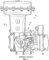
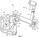
На фиг.1 схематично, с частичным вырывом, изображен известный датчик 10 положения с механической связью, установленный на конце поворотного привода 60. Датчик 10 положения содержит узел 12 рычага обратной связи с рычагом 14 обратной связи и роликом 15, ось 16, торсионную пружину 17 рычага, связанную с пружиной перемычку 18, поджимающую пружину 19, плечо 20 с прорезью 22, а также блок 30 датчика. Данный блок 30 содержит рычаг 32, подсоединенный к потенциометру 34 и к поджимающей пружине 19, и палец 36, выступающий из рычага 32 и входящий в прорезь 22. Датчик 10 положения помещен в корпус 40, у которого имеется адаптирующий крепежный компонент 42 и крепежная рамка 44. У крепежной рамки 44 имеется выступающий в поперечном направлении кожух 46 для приема, с возможностью поворота, оси 16. На крепежную рамку 44 корпуса 40 установлен клапанный контроллер 50.Figure 1 schematically, with a partial tear, shows a known
Поворотный привод 60 содержит поворотный приводной вал 62, который может перемещаться под действием штока 64 клапана. Данный вал 62 несет кулачок 66 с наклонной поверхностью, с которой взаимодействует ролик 15 датчика 10 положения. Регулирующий компонент (не показан) приводится в действие поворотным приводным валом 62, обеспечивая тем самым регулирование потока через клапан.The
Для обеспечения функционирования поворотного привода 60, проиллюстрированного на фиг.1, на клапанный контроллер 50, управляющий данным приводом 60, подается сигнал управления от компьютера (блока), управляющего процессом (не изображен). Активация поворотного привода 60 заставляет подвижный шток 64 опускаться вниз, поворачивая при этом поворотный приводной вал 62, кулачок 66 с наклонной поверхностью и регулирующий компонент (не изображен). Ролик 15 и рычаг 14 обратной связи поворачиваются вокруг оси 16, в результате чего плечо 20 с прорезью 22 заставляет перемещаться палец 36 и рычаг 32, воздействующий на потенциометр 34. Электрический сигнал от потенциометра 34 (соответствующий, например, изменяющемуся значению его сопротивления) передается клапанному контроллеру 50. Этот электрический сигнал соответствует положению поворотного приводного вала 62 и регулирующего компонента, так что компьютер, управляющий процессом, может определить положение регулирующего компонента и подать, через клапанный контроллер 50 и поворотный привод 60, любой подходящий корректирующий сигнал или новый сигнал управления.To ensure the operation of the
В случае монтажа на конце поворотного привода или в устройствах обратной связи с дистанционным размещением механические связи датчика 10 положения по фиг.1 могут быть вынуждены работать в тяжелых условиях. Поджимающая пружина 19 прикладывает к рычагу 32 и пальцу 36 значительное усилие, так что при работе в тяжелых условиях палец 36 может быть срезан плечом 20. При этом в механических связях датчика 10 положения могут возникнуть и другие точки износа, что приведет к разрыву соединения между штоком 64 клапана и клапанным контроллером 50.In the case of mounting at the end of a rotary actuator or in feedback devices with remote placement, the mechanical connections of the
Приводы с большим перемещением или с большой длиной хода, как правило, имеют части, которые вращаются и вибрируют в большей степени, чем аналогичные части приводов с коротким ходом. Как следствие, для бесконтактных датчиков положения в этих приводах возникают проблемы, связанные с их настройкой и вибрацией. Известный бесконтактный датчик положения приводов с коротким ходом требует использования большого количества магнитов в магнитном модуле. Использование бесконтактного датчика положения, рассчитанного на привод с коротким ходом, в приводе с длинным ходом или на конце поворотного привода, или в блоке обратной связи с дистанционным размещением для измерения перемещения может потребовать использования относительно большого количества магнитов. Бесконтактный датчик положения с подобным, относительно большим, количеством магнитов может оказаться дорогостоящим и требующим большого времени на его изготовление.Drives with a large displacement or with a long stroke, as a rule, have parts that rotate and vibrate to a greater extent than similar parts of drives with a short stroke. As a result, for non-contact position sensors in these drives there are problems associated with their adjustment and vibration. The known non-contact encoder for short-stroke actuators requires the use of a large number of magnets in the magnetic module. The use of a proximity encoder designed for a short-stroke actuator in a long-stroke actuator or at the end of a rotary actuator, or in a remote-position feedback unit for measuring displacement, may require the use of a relatively large number of magnets. A non-contact position sensor with a similar, relatively large number of magnets can be expensive and time consuming to produce.
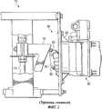
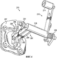
На фиг.2 схематично, с частичным вырывом, представлен известный датчик 80 положения, установленный на части привода 70 со скользящим штоком, имеющим большой ход. Данный привод 70 содержит подвижный шток 74 клапана, несущий кулачок 76 со скошенной или наклонной поверхностью. Регулирующий компонент (не изображен) приводится в действие подвижным штоком 74 клапана, чтобы регулировать поток через клапан. Кулачок 76 со скошенной или наклонной поверхностью находится в скользящем контакте с роликом 85, установленным на рычаге 86 обратной связи, который выполнен с возможностью качания на оси 88 датчика 80 положения. Датчик 80 положения имеет механические связи и потенциометр, схожие с аналогичными компонентами датчика 10 положения, проиллюстрированного на фиг.1; поэтому в их описании нет необходимости. Датчик 80 положения закреплен посредством крепежной рамки 90, к которой прикреплен клапанный контроллер 95.Figure 2 schematically, with a partial tear, presents a known
Привод 70 с большим ходом и датчик 80 положения функционируют аналогично тому, как это было описано применительно к поворотному приводу 60 и датчику 10 положения, представленным на фиг.1. Сигнал управления от компьютера, управляющего процессом (не изображен), передается клапанному контроллеру 95, который приводит в действие привод 70. Срабатывание привода 70 заставляет шток 74 клапана опускаться вниз, перемещая регулирующий компонент и смещая скошенную или наклонную поверхность кулачка 76. Реагируя на движение указанной поверхности кулачка 76, ролик 85 и рычаг 86 обратной связи поворачиваются вокруг оси 88, приводя в действие датчик 80 положения. Датчик 80 положения передает электрический сигнал клапанному контроллеру 95, который связан с компьютером, управляющим процессом. Таким образом, электрический сигнал соответствует положению подвижного штока 74 клапана и регулирующего компонента, так что компьютер, управляющий процессом, может определить положение регулирующего компонента и подать, через клапанный контроллер 95 и привод 70 со скользящим штоком, любой подходящий корректирующий сигнал или новый сигнал управления.The high-
Использование бесконтактного датчика положения вместо датчика положения с механическими связями в приводе с большим ходом, например вместо датчика 80 положения в рассмотренном приводе 70 со скользящим штоком, потребовало бы существенного изменения конструкции и ее усовершенствования, чтобы разрешить проблему масштабирования. Так, большие вращательные усилия, прикладываемые в приводах с большим ходом к их структурным компонентам, могут привести к разрушению чувствительного элемента непосредственно подсоединяемого бесконтактного датчика положения. Кроме того, для измерения перемещения привода с большим ходом может потребоваться большое количество магнитов (в типичном случае четыре магнита на каждые 25 мм хода). Как следствие, для приводов с длиной хода, достигающей 30-60 см, было бы необходимо разработать новые магнитные блоки. Кроме того, чтобы обеспечить возможность установки бесконтактного датчика положения на подобный привод, потребовалось бы разработать новые крепежные компоненты и пластины.The use of a non-contact position sensor instead of a mechanical coupled position sensor in a long-stroke actuator, for example, instead of a
Раскрытие изобретенияDisclosure of invention
Датчик положения привода для клапана, управляемого посредством привода, содержит корпус, несущий один компонент из группы, состоящей из датчика магнитного потока и источника магнитного потока, для детектирования изменений магнитного поля, возникающих в результате относительного перемещения датчика и источника магнитного потока. Поворотный приводной рычаг несет другой компонент из указанной группы. Чтобы обеспечить относительное перемещение датчика и источника магнитного потока, указанный рычаг связан с корпусом с возможностью поворота относительно него. У поворотного приводного рычага имеется один из элементов группы, состоящей из наклонной поверхности и контактного элемента, для обеспечения подвижного контакта с другим элементом указанной группы, имеющимся на подвижном компоненте указанного клапана.The actuator position sensor for a valve controlled by an actuator comprises a housing carrying one component from the group consisting of a magnetic flux sensor and a magnetic flux source for detecting magnetic field changes resulting from the relative movement of the sensor and the magnetic flux source. The rotary drive lever carries another component from the specified group. To ensure relative movement of the sensor and the source of magnetic flux, the specified lever is connected with the housing with the possibility of rotation relative to it. The rotary actuating lever has one of the elements of the group consisting of an inclined surface and a contact element to provide movable contact with another element of the specified group, which is available on the movable component of the specified valve.
Краткое описание чертежейBrief Description of the Drawings
На фиг.1 схематично, с частичным вырывом, изображен известный датчик положения, установленный на конце поворотного привода.Figure 1 schematically, with a partial tear, depicts a known position sensor mounted on the end of a rotary actuator.
На фиг.2 схематично, с частичным вырывом, изображен известный датчик положения, установленный на приводе со скользящим штоком, имеющим большой ход.Figure 2 schematically, with a partial pullout, shows a known position sensor mounted on an actuator with a sliding rod having a long stroke.
На фиг.3 представлен пример датчика положения по изобретению.Figure 3 presents an example of a position sensor according to the invention.
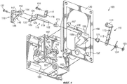
На фиг.4 датчик положения по фиг.3 показан с пространственным разделением его частей.In Fig.4, the position sensor of Fig.3 is shown with a spatial separation of its parts.
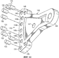
На фиг.4A представлен, с пространственным разделением частей, пример держателя набора магнитов в датчике положения по фиг.4.On figa presents, with a spatial separation of the parts, an example of a holder of a set of magnets in the position sensor of figure 4.
На фиг.5 иллюстрируются рычажный узел и набор магнитов другого варианта датчика положения.Figure 5 illustrates the lever assembly and the set of magnets of another embodiment of the position sensor.
На фиг.6 иллюстрируются рычажный узел, датчик и держатель набора магнитов еще одного варианта датчика положения.Figure 6 illustrates the lever assembly, sensor, and magnet set holder of yet another embodiment of the position sensor.
На фиг.7 представлена схематичная иллюстрация альтернативной связи между поворотным рычажным узлом магнитного датчика положения и приводом со скользящим штоком.7 is a schematic illustration of an alternative connection between a rotary link assembly of a magnetic position sensor and a sliding rod actuator.
Осуществление изобретенияThe implementation of the invention
Описываемый далее вариант устройства для определения положения привода может быть использован для детектирования или измерения смещения в приводах различных типов. Хотя варианты, рассматриваемые далее, связаны с управлением потоком продукта в промышленных обрабатывающих установках, эти варианты применимы к широкому кругу операций по управлению процессом для использования в различных целях.The following embodiment of the device for determining the position of the actuator can be used to detect or measure displacement in actuators of various types. Although the options discussed below are related to product flow control in industrial processing plants, these options are applicable to a wide range of process control operations for various purposes.
На фиг.3 иллюстрируется вариант датчика 100 положения. Указанный датчик 100 содержит рычажный узел 110, крепежную рамку 120, корпус 130 контроллера и собственно датчик 160. Корпус 130 контроллера прикреплен к крепежной рамке 120. Как показано на фиг.3, рычажный узел 110 содержит приводной рычаг 112 с отверстием 113 и с контактным элементом (роликом) 114, регулировочный рычаг 116, узел 118 оси и держатель 140 набора магнитов.FIG. 3 illustrates an embodiment of a
На фиг.4 вариант датчика 100 положения по фиг.3 показан с пространственным разделением его частей. Рычажный узел 110 содержит ролик 114, прикрепленный к дистальному концу приводного рычага 112. Однако, если необходимо изменить диапазон поворота приводного рычага 112, чтобы использовать данный вариант датчика 100 положения с приводом другого размера или типа, ролик может быть закреплен в отверстии 113. Узел 118 оси содержит ось 119, которая по завершении сборки приваривается к приводному рычагу 112, и пару подшипников 121. На конце 122 оси имеется пружинное стопорное кольцо 123 для удерживания на оси 119 торсионной пружины 124. Конец 126 оси выступает из отверстия 129 регулировочного рычага 116.In Fig.4, a variant of the
Регулировочный рычаг 116 имеет отогнутый конец 117, жестко прикрепленный винтом 131 к приводному рычагу 112. Противоположный, присоединительный конец 133 регулировочного рычага 116, выполняющий функцию фланца, снабжен отверстием 129, через которое проходит конец 126 оси, определяющий положение указанного конца 133 относительно приводного рычага 112. Присоединительный конец 133 регулировочного рычага 116 снабжен также резьбовым отверстием 135 для приема винта 137.The adjusting
В варианте по фиг.4 держатель 140 набора магнитов имеет форму дугового сектора и снабжен на своем узком конце 144 отверстием 142 для приема конца 126 оси. На своем широком конце 146 сектор имеет отверстие 147 для приема винта 137. Секторный держатель 140 набора магнитов согласован по положению с присоединительным концом 133 регулировочного рычага 116 и прикреплен к нему за счет ввода конца 126 оси в отверстие 142 и винта 137 в отверстия 147 и 135.In the embodiment of FIG. 4, the magnet set
Как показано на фиг.4A, на широком конце 146 держателя 140 набора магнитов имеется группа отверстий 148a-148e, расположенных между парами отверстий 149 и 151. В каждом из отверстий 148a, 148b, 148d и 148e закреплен дискретный цилиндрический магнит 155. В каждое из отверстий 149 и 151, образующих пары отверстий, введен дискретный магнит 155. Отверстие 148с не содержит магнита. Таким образом, в данном варианте секторный держатель 140 набора магнитов несет 8 магнитов 155, образующих поворотный источник 170 магнитного потока. Разумеется, для создания соответствующего источника описанного типа, аналогичного источнику 170, можно использовать другие количества магнитов и держатели набора магнитов иной формы.4A, at the
Магниты 155, находящиеся в отверстиях 149, 148a и 148b, расположенных над отверстием 148c, размещены таким образом, что при повороте держателя 140 набора магнитов с переходом от пары отверстий 149 к отверстию 148b индукция, создаваемая источником 170 магнитного потока, изменяется от высокого до низкого значения. Индукция у отверстия 148с равна нулю вследствие отсутствия в нем магнита. Аналогично, индукция, создаваемая данным источником 170, возрастает от низкого до высокого значения при повороте держателя 140 набора магнитов от отверстия 148d до пары отверстий 151. Таким образом, сигналы, формируемые датчиком 100 положения, позволяют определить как величину, так и направление поворота держателя 140 набора магнитов относительно отверстия 148c.The
Как показано на фиг.4, у крепежной рамки 120 имеется наружный фланец 150, выступающий в поперечном направлении кожух 156 оси с отверстием 156a, гнезда 157 и центральное отверстие 158. На фиг.4 наружный фланец 150 показан снабженным отверстиями, облегчающими прикрепление рамки 120 к приводу (не изображен) посредством винтов или болтов; однако, рамка 120 может крепиться к приводу и с помощью многих других средств, таких как сварка, съемные зажимы, петля и запор, адгезив и т.д. Хотя это и не показано, каждое из гнезд 157 на своем противоположном конце имеет резьбовое отверстие.As shown in FIG. 4, the mounting
В корпусе 130 контроллера может находиться клапанный контроллер (не изображен). Этот корпус 130 снабжен винтами 162, установленными с возможностью ввода в неизображенные резьбовые отверстия в гнездах 157 крепежной рамки 120. Собственно датчик 160 установлен в отверстии 161, имеющемся в соответствующей части корпуса 130. Датчик 160 имеет воспринимающую поток U-образную полюсную деталь 163 с зубцами 164. Датчик 100 положения, представленный на фиг.3, 4 и 4A, находится в нулевом положении, когда отверстие 148с держателя 140 набора магнитов расположено между зубцами 164 полюсной детали 163. Хотя датчик 100 положения на фиг.3, 4 и 4A представлен, как датчик на эффекте Холла, должно быть понятно, что в датчике 100 положения могут быть применены и многие другие датчики магнитного потока, например магнито-резистивный датчик, мост на основе гигантского магнито-резистивного эффекта или феррозонд.In the
Как показано на фиг.4, корпус 130 контроллера прикреплен к крепежной рамке 120 посредством ввинчивания винтов 162 в резьбовые отверстия гнезд 157. При прикреплении корпуса 130 контроллера к крепежной рамке 120 датчик 160 входит в центральное отверстие 158, имеющееся в крепежной рамке 120. Разумеется, могут быть использованы и другие способы прикрепления корпуса 130 контроллера к крепежной рамке 120.As shown in FIG. 4, the
На фиг.3 датчик 100 положения, крепежная рамка 120 и корпус 130 контроллера показаны в собранном виде, т.е. в готовности к использованию. Корпус 130 контроллера прикреплен к крепежной рамке 120, а ось 119 и подшипники 121 узла 110 оси введены, с возможностью поворота, в отверстие 156a выступающего в поперечном направлении кожуха 156 (см. фиг.4). Секторный держатель 140 набора магнитов прикреплен к регулировочному рычагу 116 рычажного узла 110. Корпус 130 контроллера обеспечивает установку U-образной детали 163 (фиг.4) датчика 160 перпендикулярно оси 119, введенной, с возможностью поворота, в отверстие 156a кожуха 156. В одном из вариантов поворотный источник 170 магнитного потока установлен с возможностью поворота между зубцами 164 детали 163 примерно на 30°.3, the
Датчик 100 положения срабатывает в результате подвижного взаимодействия контактного элемента (ролика) 114 рычажного узла 110 с наклонной поверхностью на подвижном компоненте привода, такой, например, как наклонная поверхность кулачка 66 на подвижном штоке 64 клапана (см. фиг.1) или скошенная (наклонная) поверхность кулачка 76 подвижного штока 74 клапана (см. фиг.2). При этом положение ролика 114 не зафиксировано жестко относительно подвижного компонента, в частности относительно указанных поверхностей кулачков 66 и 76. Подвижное взаимодействие между роликом 114 и подвижным компонентом привода может быть любого типа при условии, что между нежестко связанными частями имеет место относительное движение, например качение, скольжение, отклонение и т.д. Хотя на фиг.3 ролик 114 показан прикрепленным к той же стороне приводного рычага 112, что и регулировочный рычаг 116, ролик 114 может быть прикреплен и к противоположной стороне этого рычага 112, чтобы обеспечить контакт с подвижным компонентом другого варианта привода.The
Когда ролик 114 и соответственно рычажный узел 110 смещаются в результате перемещения подвижного компонента привода, происходит поворот рычажного узла 110, узла 118 оси и держателя 140 набора магнитов относительно кожуха 156 оси. Каждый дискретный магнит 155 источника 170 магнитного потока создает магнитное поле различной напряженности, чтобы обеспечить передачу определенной магнитной энергии или определенную индукцию. Датчик 100 положения обеспечивает линейную зависимость между углом поворота держателя 140 набора магнитов и выходным сигналом датчика 160, поступающим в виде электрического сигнала на клапанный контроллер (не изображен), установленный в корпусе 130 контроллера. Клапанный контроллер связан с компьютером, управляющим процессом (не изображен), который определяет положение регулирующего компонента, перемещаемого посредством привода. Компьютер, управляющий процессом, может выдать клапанному контроллеру и, соответственно, приводу любой корректирующий сигнал или новый сигнал управления, чтобы изменить положение регулирующего компонента.When the
Показанные на фиг.4A два магнита 155, расположенные в паре отверстий 149 и 151, формируют концевой эффект для датчика 100 положения. Когда представленный держатель 140 набора магнитов поворачивается примерно на 15° в любом направлении относительно своего нулевого положения, рассматриваемый вариант датчика 100 положения детектирует значительное изменение индукции магнитов 155, введенных в одну из пар отверстий 149, 151. Поскольку датчик 100 положения связан с клапанным контроллером и через него с компьютером, управляющим процессом, данный компьютер опознает значительное изменение индукции источника 170 магнитного потока как указание на то, что датчик 100 положения находится в крайней точке своего поворота, которая соответствует конечной точке перемещения регулирующего компонента (например, что магниты 155 в любой из пары отверстий 149 или 151 находятся между зубцами 164 полюсной детали 163). Благодаря использованию двух магнитов 155 для создания значительного изменения индукции или напряженности поля в конечных точках поворота держателя 140 набора магнитов (т.е. в парах отверстий 149 и 151) сокращается общее количество магнитов, требуемых для датчика 100 положения. Действительно, датчик положения, использующий одиночные магниты, установленные в ряд, дает более плавное изменение индукции, что вызывает необходимость в существенно большем количестве магнитов.Shown in FIG. 4A, two
На фиг.5 иллюстрируются рычажный узел и набор магнитов другого варианта датчика положения. Данный датчик 200 положения использует альтернативную конфигурацию для установки рычажного узла 210 и поворотного держателя 240 набора магнитов. Датчик 200 положения содержит рычажный узел 210, ось 218, корпус 232 контроллера, держатель 240 набора магнитов и дискретные магниты 255.Figure 5 illustrates the lever assembly and the set of magnets of another embodiment of the position sensor. This
Рычажный узел 210 содержит приводной рычаг 212 с отверстием 213 и контактный элемент (ролик) 214. Этот узел прикреплен к оси 218, которая снабжена двумя концевыми отрезками 219, установленными в подшипниках 221. Ось 218 прикреплена к поворотному держателю 240 набора магнитов, согласованному по положению с собственно датчиком 260. Дискретные магниты 255 в поворотном держателе 240 магнитов формируют поворотный источник 270 магнитного потока. На конце 222 оси (точнее, на ее концевом отрезке 219) установлена торсионная пружина 224. Каждый из пары стационарных выступов 230, 231 снабжен отверстием (не изображено) для приема одного из подшипников 221, установленных на концевых отрезках 219 оси. Эти выступы могут являться частью корпуса 232 контроллера или крепежной рамки (не изображена), или любого иного стационарного корпусного элемента, пригодного для формирования выступов 230 и 231. Держатель 240 набора магнитов расположен между зубцами 264 воспринимающей поток U-образной полюсной детали 263 датчика 260.The
Аналогично тому, как это было описано применительно к датчику 100 положения по фиг.3, датчик 200 положения по фиг.5 срабатывает в результате подвижного взаимодействия ролика 214 рычажного узла 210 с подвижным компонентом привода. Когда рычажный узел 210 и ось 218 поворачиваются относительно стационарных выступов 230, 231, держатель 240 набора магнитов вместе с дискретными магнитами 255 поворачиваются относительно датчика 260. При повороте дискретных магнитов 255 изменяется поток от источника 270, в результате чего датчик 260 посылает соответствующий электрический сигнал на клапанный контроллер (не изображен).In the same way as described with reference to the
На фиг.6 иллюстрируются рычажный узел, датчик и держатель набора магнитов еще одного варианта датчика положения. Представленный датчик 275 положения реализует альтернативную конфигурацию с поворотным датчиком 280 и со стационарным держателем 290 набора магнитов. Данный датчик 275 положения содержит рычажный узел 210, ролик 214, ось 218 и стационарные выступы 230 и 231, идентичные показанным на фиг.5. Датчик 275 положения содержит также поворотный датчик 280, жестко прикрепленный к оси 218 рычажного узла 210, и стационарный держатель 290 набора магнитов, жестко прикрепленный к корпусу 297 контроллера. Стационарный держатель 290 набора магнитов несет дискретные магниты 295, формирующие стационарный источник 296 магнитного потока. Данный держатель 290 расположен между зубцами 284 воспринимающей поток U-образной полюсной детали 283 поворотного датчика 280.Figure 6 illustrates the lever assembly, sensor, and magnet set holder of yet another embodiment of the position sensor. The presented
Как было описано применительно к датчику 200 положения по фиг.5, датчик 275 положения по фиг.6 также срабатывает в результате взаимодействия ролика 214 рычажного узла 210 с подвижным компонентом привода. Когда рычажный узел 210 и ось 218 поворачиваются относительно стационарных выступов 230, 231, поворотный датчик 280 поворачивается относительно стационарного держателя 290 набора магнитов и дискретных магнитов 295. При повороте поворотного датчика 280 изменяется воспринимаемый им поток от источника 296, в результате чего поворотный датчик 280 посылает соответствующий электрический сигнал на клапанный контроллер (не изображен).As described with reference to the
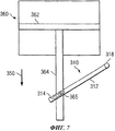
На фиг.7 схематично иллюстрируется рычажный узел 310 магнитного датчика положения (не изображен), связанного с подвижным штоком 364 клапана в приводе 360 со скользящим штоком. Данный привод 360 содержит поршень 362, прикрепленный к подвижному штоку 364 клапана, у которого имеется контактный элемент (палец) 365. Рычажный узел 310 магнитного датчика положения содержит приводной рычаг 312, имеющий прорезь или иную направляющую 314, в которой со скольжением перемещается палец 365 и которая тем самым обеспечивает наклонную поверхность на приводном рычаге 312.7 schematically illustrates the
Приводной рычаг 312, который поворачивается вокруг оси 318 поворота, связан с датчиком или с источником магнитного потока (не изображен), например подобными описанным выше со ссылками на фиг.3-6. Альтернативно, приводной рычаг 312 может быть механически прикреплен к поворотному датчику положения с единственным магнитом, например аналогичному поворотному датчику положения с единственным источником магнитного потока, описанному в принадлежащих заявителю настоящего изобретения патентах США №№6909281 B2 и 7005847 B2, содержание которых полностью включено в данное описание посредством ссылки. В процессе функционирования привода 360 поршень 362 опускается вниз, чтобы сместить подвижный шток 364 клапана в направлении, обозначенном стрелкой 350. При опускании пальца 365 на подвижном штоке 364 клапана вместе с данным штоком этот палец скользит в направляющей 314 и поворачивает приводной рычаг 312, приводя в действие магнитный датчик положения. Хотя направляющая 314 изображена в виде сквозной прорези, она может быть реализована и в другой конструкции с использованием скольжения, например в виде пальца, взаимодействующего с параллельными поверхностями, поворотного пальца в канавке или отверстии и т.д.A
Хотя выше были описаны конкретные варианты предлагаемого устройства, объем охраны изобретения не ограничивается этими вариантами, а распространяется на любые устройства или иные изделия, охватываемые прилагаемой формулой изобретения как буквально, так и с учетом доктрины эквивалентов.Although specific options for the proposed device have been described above, the scope of protection of the invention is not limited to these options, but applies to any devices or other products covered by the attached claims both literally and taking into account the doctrine of equivalents.
Claims (22)
корпус, несущий один компонент из группы, состоящей из датчика магнитного потока и источника магнитного потока для детектирования изменений магнитного поля, возникающих в результате относительного перемещения датчика магнитного потока и источника магнитного потока;
поворотный приводной рычаг, несущий другой компонент из указанной группы и обеспечивающий относительное перемещение датчика магнитного потока и источника магнитного потока, при этом у поворотного приводного рычага имеется один элемент из группы, состоящей из наклонной поверхности и контактного элемента для обеспечения подвижного контакта с другим элементом указанной группы, имеющимся на подвижном компоненте указанного клапана, причем
поворотный приводной рычаг связан с корпусом с возможностью поворота относительно него.1. A position sensor for a valve controlled by an actuator, comprising:
a housing carrying one component from the group consisting of a magnetic flux sensor and a magnetic flux source for detecting magnetic field changes resulting from the relative movement of the magnetic flux sensor and the magnetic flux source;
a rotary drive arm carrying another component from the specified group and providing relative movement of the magnetic flux sensor and the magnetic flux source, while the rotary drive arm has one element from the group consisting of an inclined surface and a contact element to provide movable contact with another element of the specified group existing on the movable component of the specified valve, and
the pivoting drive arm is rotatably coupled to the housing.
корпус, несущий один компонент из группы, состоящей из датчика магнитного потока и источника магнитного потока для детектирования изменений магнитного поля, возникающих в результате относительного перемещения датчика магнитного потока и источника магнитного потока;
поворотный приводной рычаг, несущий другой компонент из указанной группы и обеспечивающий относительное перемещение датчика магнитного потока и источника магнитного потока, при этом у поворотного приводного рычага имеется один элемент из группы, состоящей из наклонной поверхности и контактного элемента для обеспечения подвижного контакта с другим элементом указанной группы, имеющимся на подвижном компоненте, причем
поворотный приводной рычаг связан с корпусом с возможностью поворота относительно него.13. A position sensor assembly comprising:
a housing carrying one component from the group consisting of a magnetic flux sensor and a magnetic flux source for detecting magnetic field changes resulting from the relative movement of the magnetic flux sensor and the magnetic flux source;
a rotary drive arm carrying another component from the specified group and providing relative movement of the magnetic flux sensor and the magnetic flux source, while the rotary drive arm has one element from the group consisting of an inclined surface and a contact element to provide movable contact with another element of the specified group existing on the movable component, and
the pivoting drive arm is rotatably coupled to the housing.
корпус, несущий датчик магнитного потока для детектирования изменений магнитного поля, возникающих в результате относительного перемещения датчика магнитного потока и источника магнитного потока;
поворотный приводной рычаг, несущий источник магнитного потока и обеспечивающий относительное перемещение датчика магнитного потока и источника магнитного потока, при этом у источника магнитного потока имеется дуговой участок, на котором установлен набор дискретных магнитов, а поворотный приводной рычаг выполнен с возможностью нести поворотный контактный элемент для обеспечения подвижного контакта с наклонной поверхностью, имеющейся на подвижном компоненте привода указанного клапана, причем
поворотный приводной рычаг связан с корпусом с возможностью поворота относительно него.20. A position sensor for a valve controlled by an actuator, comprising:
a housing carrying a magnetic flux sensor for detecting magnetic field changes resulting from the relative movement of the magnetic flux sensor and the magnetic flux source;
a rotary drive lever carrying a magnetic flux source and providing relative movement of the magnetic flux sensor and the magnetic flux source, while the magnetic flux source has an arc portion on which a set of discrete magnets is mounted, and the rotary drive arm is configured to carry a rotary contact element to provide movable contact with an inclined surface existing on the movable component of the actuator of the specified valve, and
the pivoting drive arm is rotatably coupled to the housing.
Applications Claiming Priority (2)
| Application Number | Priority Date | Filing Date | Title |
|---|---|---|---|
| US11/518,784 | 2006-09-11 | ||
| US11/518,784 US7609056B2 (en) | 2006-09-11 | 2006-09-11 | Apparatus to determine the position of an actuator |
Publications (2)
| Publication Number | Publication Date |
|---|---|
| RU2009112050A RU2009112050A (en) | 2010-10-20 |
| RU2445539C2 true RU2445539C2 (en) | 2012-03-20 |
Family
ID=39092060
Family Applications (1)
| Application Number | Title | Priority Date | Filing Date |
|---|---|---|---|
| RU2009112050/06A RU2445539C2 (en) | 2006-09-11 | 2007-08-30 | Device to detect drive position |
Country Status (11)
| Country | Link |
|---|---|
| US (1) | US7609056B2 (en) |
| EP (1) | EP2061984B1 (en) |
| JP (1) | JP5244107B2 (en) |
| CN (1) | CN101512203B (en) |
| AR (1) | AR062722A1 (en) |
| BR (1) | BRPI0715902A2 (en) |
| CA (1) | CA2662802C (en) |
| DE (1) | DE602007009552D1 (en) |
| MX (1) | MX2009002424A (en) |
| RU (1) | RU2445539C2 (en) |
| WO (1) | WO2008033675A2 (en) |
Families Citing this family (40)
| Publication number | Priority date | Publication date | Assignee | Title |
|---|---|---|---|---|
| US7444401B1 (en) | 2002-11-18 | 2008-10-28 | Arkion Systems Llc | Method and apparatus for inexpensively monitoring and controlling remotely distributed appliances |
| US20080197948A1 (en) * | 2006-12-13 | 2008-08-21 | Stoneridge Control Devices, Inc. | Cylinder Position Sensor and Cylinder Incorporating the Same |
| US20090278641A1 (en) * | 2006-12-13 | 2009-11-12 | Stoneridge Control Devices, Inc. | Cylinder Position Sensor and Cylinder Incorporating the Same |
| CA2997878A1 (en) | 2008-10-27 | 2010-05-06 | Mueller International, Llc | Infrastructure monitoring system and method |
| CA2772545C (en) | 2009-05-22 | 2018-12-11 | Mueller International, Inc. | Infrastructure monitoring devices, systems, and methods |
| JP5654124B2 (en) | 2010-06-16 | 2015-01-14 | ミューラー インターナショナル エルエルシーMueller International,Llc | Infrastructure monitoring apparatus, system, and method |
| US8596295B2 (en) * | 2010-06-16 | 2013-12-03 | Mueller International, Llc | Mechanical position indicator |
| US8833390B2 (en) | 2011-05-31 | 2014-09-16 | Mueller International, Llc | Valve meter assembly and method |
| US8960224B2 (en) | 2011-08-18 | 2015-02-24 | Cameron International Corporation | Valve position translator |
| WO2013028552A1 (en) * | 2011-08-19 | 2013-02-28 | General Equipment And Manufacturing Company, Inc., D/B/A Topworx, Inc. | Methods and apparatus to determine a position of a valve |
| NO333570B1 (en) * | 2011-10-12 | 2013-07-08 | Electrical Subsea & Drilling As | Device for valve actuator with spring return and method for operating a valve |
| US8660134B2 (en) | 2011-10-27 | 2014-02-25 | Mueller International, Llc | Systems and methods for time-based hailing of radio frequency devices |
| US8855569B2 (en) | 2011-10-27 | 2014-10-07 | Mueller International, Llc | Systems and methods for dynamic squelching in radio frequency devices |
| CA2872549C (en) | 2012-05-25 | 2021-04-13 | Mueller International, Llc | Position indicator for valves |
| US9097269B2 (en) * | 2012-06-04 | 2015-08-04 | Fisher Controls International, Llc | Bracket assemblies for use with actuators |
| US9423050B2 (en) * | 2013-04-09 | 2016-08-23 | Fisher Controls International Llc | Intelligent actuator and method of monitoring actuator health and integrity |
| JP5800207B2 (en) * | 2013-05-10 | 2015-10-28 | 株式会社デンソー | Rotation position detector |
| CN103363186A (en) * | 2013-07-26 | 2013-10-23 | 常熟市华夏仪表有限公司 | Shaft feedback device of electro-pneumatic valve positioner |
| US9618136B2 (en) | 2013-09-16 | 2017-04-11 | Fisher Controls International Llc | Rotary valve position indicator |
| US9772046B2 (en) * | 2013-12-05 | 2017-09-26 | Badger Meter, Inc. | Method and apparatus for mounting a control valve positioner |
| US9494249B2 (en) | 2014-05-09 | 2016-11-15 | Mueller International, Llc | Mechanical stop for actuator and orifice |
| US9599502B2 (en) * | 2014-07-22 | 2017-03-21 | Fisher Controls International Llc | Magnetic field sensor feedback for diagnostics |
| US9565620B2 (en) | 2014-09-02 | 2017-02-07 | Mueller International, Llc | Dynamic routing in a mesh network |
| US9777855B2 (en) * | 2014-11-17 | 2017-10-03 | Regulator Technologies Tulsa, Llc | Pressure vacuum relief valve providing monitoring capabilities |
| US9945701B2 (en) * | 2015-07-17 | 2018-04-17 | Fisher Controls International Llc | Actuator bracket having a sensor |
| US20170307411A1 (en) * | 2016-04-22 | 2017-10-26 | KSR IP Holdings, LLC | Position sensor |
| US10234058B2 (en) | 2016-10-20 | 2019-03-19 | Fisher Controls International Llc | Methods and apparatus of assessing a test of a solenoid valve via a positioner |
| US10240687B2 (en) | 2016-10-20 | 2019-03-26 | Fisher Controls International Llc | Methods and apparatus of testing a solenoid valve of an emergency valve via a positioner |
| US10041610B2 (en) * | 2016-10-20 | 2018-08-07 | Fisher Controls International Llc | Methods and apparatus of stabilizing a valve positioner when testing a solenoid valve |
| US10466093B2 (en) | 2017-07-12 | 2019-11-05 | Sikorsky Aircraft Corporation | Failsafe electromechanical weight on wheels detection |
| US10711907B2 (en) | 2017-11-07 | 2020-07-14 | Black Diamond Engineering, Inc. | Line replaceable control valve positioner/controller system |
| US10865817B2 (en) | 2018-10-10 | 2020-12-15 | Dresser, Llc | Compensating for orientation of a valve positioner on a valve assembly |
| DE102018217281A1 (en) * | 2018-10-10 | 2020-04-16 | Continental Teves Ag & Co. Ohg | Angle sensor for detecting an angle of rotation |
| US11174964B2 (en) * | 2018-10-29 | 2021-11-16 | Fisher Controls International Llc | Position transmitter assemblies for use with actuators |
| US11454334B1 (en) * | 2021-04-09 | 2022-09-27 | Dresser, Llc | Accuracy of control valves using a short-stroke position converter |
| US11536393B2 (en) | 2021-04-12 | 2022-12-27 | Fisher Controls International Llc | Travel feedback system |
| DE102021129496A1 (en) | 2021-11-12 | 2023-05-17 | Samson Aktiengesellschaft | Sensor device, measuring arrangement and method for assembling a sensor device |
| WO2023229651A1 (en) * | 2022-05-25 | 2023-11-30 | Dresser, Llc | Improving accuracy of control valves using a long-stroke position converter |
| WO2023229650A1 (en) * | 2022-05-25 | 2023-11-30 | Dresser, Llc | Improving accuracy of control valves using a short-stroke position converter |
| CN117386877B (en) * | 2023-09-22 | 2024-08-30 | 安徽摩控科技有限公司 | Feedback mechanism and valve positioner |
Citations (5)
| Publication number | Priority date | Publication date | Assignee | Title |
|---|---|---|---|---|
| SU513205A1 (en) * | 1974-05-13 | 1976-05-05 | Научно-Производственное Объединение "Киеварматура" | Valve Position Sensor |
| US6382226B1 (en) * | 2001-04-17 | 2002-05-07 | Fisher Controls International, Inc. | Method for detecting broken valve stem |
| WO2004072475A2 (en) * | 2003-02-07 | 2004-08-26 | Fisher Controls International Llc | Control valve positioner mounting system |
| US6909281B2 (en) * | 2002-07-03 | 2005-06-21 | Fisher Controls International Llc | Position sensor using a compound magnetic flux source |
| DE10360434A1 (en) * | 2003-12-22 | 2005-07-21 | Samson Ag | Arrangement, position sensor, device for regulating, driving and method for detecting the position of a drivable component |
Family Cites Families (39)
| Publication number | Priority date | Publication date | Assignee | Title |
|---|---|---|---|---|
| JPS6219923Y2 (en) * | 1980-12-16 | 1987-05-21 | ||
| JPS5981511A (en) * | 1982-11-01 | 1984-05-11 | Citizen Watch Co Ltd | Detector for position of rotating shaft |
| JPS6049231U (en) * | 1983-09-12 | 1985-04-06 | 三國工業株式会社 | Carburetor throttle valve opening detection sensor mounting device |
| JPS60170719A (en) * | 1984-02-15 | 1985-09-04 | Aisin Seiki Co Ltd | Rotational angle sensor |
| JPS6115309U (en) * | 1984-06-27 | 1986-01-29 | 世紀東急工業株式会社 | Paved road surface unevenness measuring device |
| JPS61175545U (en) * | 1985-04-22 | 1986-11-01 | ||
| JPS61290303A (en) * | 1985-06-18 | 1986-12-20 | Sanshin Ind Co Ltd | Tilt angle detector for propelling unit for ship |
| US4746772A (en) * | 1986-09-23 | 1988-05-24 | Fisher Controls International, Inc. | Adjustable position indicating apparatus |
| JPH0416892Y2 (en) * | 1986-11-13 | 1992-04-15 | ||
| SE462811B (en) * | 1989-05-09 | 1990-09-03 | Hans Karlsson | DEVICE FOR CONVERSION OF A PROMOTING AND ATTACHING MOVEMENT TO A ROTATING MOVEMENT |
| JPH0744972Y2 (en) * | 1989-12-25 | 1995-10-11 | 株式会社緑測器 | Non-contact linear displacement sensor |
| TW248544B (en) * | 1991-04-03 | 1995-06-01 | Torrington Co | |
| JP2516227Y2 (en) * | 1991-09-10 | 1996-11-06 | 国産電機株式会社 | Throttle opening detection device for internal combustion engine |
| JPH0735961B2 (en) * | 1991-09-11 | 1995-04-19 | 株式会社エム・システム技研 | Displacement detection differential transformer and angle detector |
| US5164668A (en) * | 1991-12-06 | 1992-11-17 | Honeywell, Inc. | Angular position sensor with decreased sensitivity to shaft position variability |
| JP3206204B2 (en) * | 1992-05-22 | 2001-09-10 | 株式会社デンソー | Throttle position sensor |
| JP2762356B2 (en) * | 1996-09-13 | 1998-06-04 | 株式会社スリーエス | Range adjustment device in positioner |
| JPH10103562A (en) * | 1996-09-24 | 1998-04-21 | Hitachi Plant Eng & Constr Co Ltd | Valve opening/closing degree display device and valve opening/closing degree resetting method |
| US5933005A (en) * | 1997-07-29 | 1999-08-03 | Brunswick Corporation | Throttle position monitor with one stationary sensor and one movable sensor |
| JP2000234678A (en) * | 1999-02-17 | 2000-08-29 | Dainippon Printing Co Ltd | Open/close display device for control valve part and valve element provided with display device |
| JP2001153260A (en) * | 1999-11-30 | 2001-06-08 | Ishikawajima Harima Heavy Ind Co Ltd | Opening degree detection mechanism for valve |
| DE10041095B4 (en) * | 1999-12-06 | 2015-11-12 | Robert Bosch Gmbh | Device for measuring an angle and / or a torque of a rotatable body |
| DE10016636A1 (en) | 2000-04-04 | 2001-10-18 | Siemens Ag | Positioner, in particular for a valve which can be actuated by a drive |
| US6211794B1 (en) * | 2000-04-06 | 2001-04-03 | Borgwarner | Analog rotary position sensor |
| US6424928B1 (en) * | 2000-06-15 | 2002-07-23 | Eim Company, Inc. | Absolute position detector interpreting abnormal states |
| JP2002022403A (en) * | 2000-07-13 | 2002-01-23 | Tokyo Keiso Co Ltd | Displacement detector and displacement detecting method |
| US6753680B2 (en) * | 2000-11-29 | 2004-06-22 | Ronald J. Wolf | Position sensor |
| JP3757118B2 (en) * | 2001-01-10 | 2006-03-22 | 株式会社日立製作所 | Non-contact rotational position sensor and throttle valve assembly having non-contact rotational position sensor |
| JP3877998B2 (en) * | 2001-11-05 | 2007-02-07 | 株式会社山武 | Temperature information detecting device and position detecting device for angle sensor |
| US6784659B2 (en) * | 2001-12-05 | 2004-08-31 | Honeywell International Inc. | Magnetoresistive speed and direction sensing method and apparatus |
| JP3831657B2 (en) * | 2001-12-06 | 2006-10-11 | アルプス電気株式会社 | Rotation position detection sensor |
| DE20200302U1 (en) * | 2002-01-10 | 2002-03-28 | Ab Elektronik Gmbh, 59368 Werne | Rotation angle sensor |
| JP2004012299A (en) * | 2002-06-06 | 2004-01-15 | Nippon Soken Inc | Detector for detecting rotation angle for synchronous rotating machinery |
| US7023200B2 (en) * | 2002-06-18 | 2006-04-04 | Siemens Vdo Automotive Corporation | Non-contacting large angle rotary position sensor for rotating shaft |
| JP4262492B2 (en) * | 2003-02-18 | 2009-05-13 | 北海道石油共同備蓄株式会社 | Valve opening / closing device |
| MXPA05008847A (en) * | 2003-02-21 | 2005-10-18 | Fisher Controls Int | Magnetic position sensor with integrated hall effect switch. |
| US6992478B2 (en) * | 2003-12-22 | 2006-01-31 | Cts Corporation | Combination hall effect position sensor and switch |
| JP4525101B2 (en) * | 2004-02-17 | 2010-08-18 | アイシン精機株式会社 | Displacement sensor device |
| JP4184350B2 (en) * | 2005-01-26 | 2008-11-19 | 株式会社東京測器研究所 | 6 component force measuring system for wheel |
-
2006
- 2006-09-11 US US11/518,784 patent/US7609056B2/en active Active
-
2007
- 2007-08-30 BR BRPI0715902-1A2A patent/BRPI0715902A2/en active Search and Examination
- 2007-08-30 MX MX2009002424A patent/MX2009002424A/en active IP Right Grant
- 2007-08-30 JP JP2009527501A patent/JP5244107B2/en not_active Expired - Fee Related
- 2007-08-30 DE DE200760009552 patent/DE602007009552D1/en active Active
- 2007-08-30 EP EP20070841612 patent/EP2061984B1/en not_active Not-in-force
- 2007-08-30 WO PCT/US2007/077218 patent/WO2008033675A2/en active Application Filing
- 2007-08-30 CA CA 2662802 patent/CA2662802C/en not_active Expired - Fee Related
- 2007-08-30 CN CN200780033385XA patent/CN101512203B/en not_active Expired - Fee Related
- 2007-08-30 RU RU2009112050/06A patent/RU2445539C2/en not_active IP Right Cessation
- 2007-09-10 AR ARP070103985 patent/AR062722A1/en active IP Right Grant
Patent Citations (6)
| Publication number | Priority date | Publication date | Assignee | Title |
|---|---|---|---|---|
| SU513205A1 (en) * | 1974-05-13 | 1976-05-05 | Научно-Производственное Объединение "Киеварматура" | Valve Position Sensor |
| US6382226B1 (en) * | 2001-04-17 | 2002-05-07 | Fisher Controls International, Inc. | Method for detecting broken valve stem |
| US6909281B2 (en) * | 2002-07-03 | 2005-06-21 | Fisher Controls International Llc | Position sensor using a compound magnetic flux source |
| US7005847B2 (en) * | 2002-07-03 | 2006-02-28 | Fisher Controls International Llc | Position sensor using a compound magnetic flux source |
| WO2004072475A2 (en) * | 2003-02-07 | 2004-08-26 | Fisher Controls International Llc | Control valve positioner mounting system |
| DE10360434A1 (en) * | 2003-12-22 | 2005-07-21 | Samson Ag | Arrangement, position sensor, device for regulating, driving and method for detecting the position of a drivable component |
Also Published As
| Publication number | Publication date |
|---|---|
| RU2009112050A (en) | 2010-10-20 |
| CN101512203B (en) | 2011-05-04 |
| EP2061984A2 (en) | 2009-05-27 |
| JP5244107B2 (en) | 2013-07-24 |
| BRPI0715902A2 (en) | 2013-07-23 |
| DE602007009552D1 (en) | 2010-11-11 |
| WO2008033675A2 (en) | 2008-03-20 |
| CA2662802C (en) | 2011-05-03 |
| CA2662802A1 (en) | 2008-03-20 |
| US20080061769A1 (en) | 2008-03-13 |
| CN101512203A (en) | 2009-08-19 |
| JP2010502989A (en) | 2010-01-28 |
| AR062722A1 (en) | 2008-11-26 |
| US7609056B2 (en) | 2009-10-27 |
| EP2061984B1 (en) | 2010-09-29 |
| MX2009002424A (en) | 2009-03-20 |
| WO2008033675A3 (en) | 2008-05-08 |
Similar Documents
| Publication | Publication Date | Title |
|---|---|---|
| RU2445539C2 (en) | Device to detect drive position | |
| EP2035733B1 (en) | Method and rotary valve actuator | |
| US20060145112A1 (en) | Proportional directional control valve with a magnetic positioning sensor | |
| US20060017032A1 (en) | Scissor thrust valve actuator | |
| US9694500B1 (en) | Mechanism with one sensor for panel present and double sheet detection for grippers | |
| CN105339713A (en) | A flow control valve servo mechanism based on a step motor and control method thereof | |
| US8829895B2 (en) | Machine with position determination of relative rotatable members | |
| JP4134348B2 (en) | Electric actuator and control method thereof | |
| EP0651192B1 (en) | Device to indicate operating state of a linear actuation valve | |
| KR20130040766A (en) | Actuator and position detection method | |
| CN107187860B (en) | A kind of parallel clamping device clamping small parts | |
| CN211574386U (en) | Position transducer assembly for use with an actuator stem of an actuator | |
| CN109051951B (en) | Position remote adjusting device and deviation correcting system | |
| KR200276160Y1 (en) | An electro-pneumatic positioner with a feedback shaft rotation detecting mechanism | |
| CN220668565U (en) | Online operation valve debugging-free replacement positioner | |
| KR20170076780A (en) | Contactless position sensor with circuit structure for sensing the position of a pointer mounted to a movable part | |
| CN115789325B (en) | Synchronous rotating mechanism applied to valve | |
| SG11201909609WA (en) | Flow rate regulating valve and fluid control apparatus using the same | |
| US20210213623A1 (en) | Teachable Gripper Sensor | |
| CN220930339U (en) | Magnetic induction mechanical switch | |
| GB2399455A (en) | Switch | |
| JP2009148830A (en) | Device for processing workpiece | |
| CN105547688A (en) | Testing device for dynamic valve element of solenoid valve | |
| KR100430811B1 (en) | Valve position measuring device | |
| JPH0419402A (en) | Positioner |
Legal Events
| Date | Code | Title | Description |
|---|---|---|---|
| MM4A | The patent is invalid due to non-payment of fees |
Effective date: 20200831 |