RU2442257C2 - Device for prevention of permanent magnet direct current motor overload - Google Patents
Device for prevention of permanent magnet direct current motor overload Download PDFInfo
- Publication number
- RU2442257C2 RU2442257C2 RU2009107021/07A RU2009107021A RU2442257C2 RU 2442257 C2 RU2442257 C2 RU 2442257C2 RU 2009107021/07 A RU2009107021/07 A RU 2009107021/07A RU 2009107021 A RU2009107021 A RU 2009107021A RU 2442257 C2 RU2442257 C2 RU 2442257C2
- Authority
- RU
- Russia
- Prior art keywords
- speed
- engine
- threshold
- overload
- sensor
- Prior art date
Links
- 230000002265 prevention Effects 0.000 title abstract description 32
- 238000000034 method Methods 0.000 claims abstract description 50
- 238000012544 monitoring process Methods 0.000 claims abstract description 15
- 230000005355 Hall effect Effects 0.000 claims description 15
- 238000005259 measurement Methods 0.000 claims description 14
- 230000003287 optical effect Effects 0.000 claims description 7
- 239000000463 material Substances 0.000 claims description 2
- 238000001514 detection method Methods 0.000 claims 3
- 230000000694 effects Effects 0.000 abstract description 2
- 238000004870 electrical engineering Methods 0.000 abstract 1
- 239000000126 substance Substances 0.000 abstract 1
- 230000008569 process Effects 0.000 description 23
- 239000003990 capacitor Substances 0.000 description 4
- 230000008859 change Effects 0.000 description 4
- 230000006870 function Effects 0.000 description 4
- 230000007613 environmental effect Effects 0.000 description 3
- 230000005284 excitation Effects 0.000 description 3
- 230000007257 malfunction Effects 0.000 description 3
- 230000005405 multipole Effects 0.000 description 3
- 238000004590 computer program Methods 0.000 description 2
- 238000010586 diagram Methods 0.000 description 2
- 230000001012 protector Effects 0.000 description 2
- 230000001419 dependent effect Effects 0.000 description 1
- 238000005516 engineering process Methods 0.000 description 1
- 238000010438 heat treatment Methods 0.000 description 1
- 230000004044 response Effects 0.000 description 1
Images
Classifications
-
- H—ELECTRICITY
- H02—GENERATION; CONVERSION OR DISTRIBUTION OF ELECTRIC POWER
- H02H—EMERGENCY PROTECTIVE CIRCUIT ARRANGEMENTS
- H02H7/00—Emergency protective circuit arrangements specially adapted for specific types of electric machines or apparatus or for sectionalised protection of cable or line systems, and effecting automatic switching in the event of an undesired change from normal working conditions
- H02H7/08—Emergency protective circuit arrangements specially adapted for specific types of electric machines or apparatus or for sectionalised protection of cable or line systems, and effecting automatic switching in the event of an undesired change from normal working conditions for dynamo-electric motors
- H02H7/093—Emergency protective circuit arrangements specially adapted for specific types of electric machines or apparatus or for sectionalised protection of cable or line systems, and effecting automatic switching in the event of an undesired change from normal working conditions for dynamo-electric motors against increase beyond, or decrease below, a predetermined level of rotational speed
Landscapes
- Control Of Electric Motors In General (AREA)
- Control Of Direct Current Motors (AREA)
- Control Of Motors That Do Not Use Commutators (AREA)
- Combined Controls Of Internal Combustion Engines (AREA)
Abstract
Description
Настоящая международная заявка имеет своей основой и подтверждает приоритет заявки США с серийным номером 11/461170, поданной 31 июля 2006 г. и озаглавленной “Устройство для предотвращения перегрузки двигателя постоянного тока с возбуждением от постоянных магнитов”, полное содержание которой включено здесь путем ссылки.This international application is based on and confirms the priority of the US application with serial number 11/461170, filed July 31, 2006 and entitled "Device for preventing overload of a DC motor with excitation from permanent magnets", the full contents of which are incorporated herein by reference.
ОБЛАСТЬ ТЕХНИКИ, К КОТОРОЙ ОТНОСИТСЯ ИЗОБРЕТЕНИЕFIELD OF THE INVENTION
Настоящее изобретение относится к способу, системе и устройству для предотвращения состояний перегрузки в двигателях, более конкретно, в двигателях постоянного тока с возбуждением от постоянных магнитов, например, как используемые в возвратно-поступательных или поворотных приводах.The present invention relates to a method, system and device for preventing overload conditions in motors, more particularly in DC motors with permanent magnet excitation, for example, as used in reciprocating or rotary drives.
УРОВЕНЬ ТЕХНИКИBACKGROUND
Традиционно в двигателях каким-либо образом отслеживается ток для предотвращения перегрузок. Это может выполняться с помощью переключателя с термовозбуждением, обычно именуемого устройством тепловой защиты. Для этого аппарата требуется, чтобы состояние перегрузки присутствовало в течение некоторого периода времени для нагревания термоэлемента, от нескольких секунд до нескольких минут в зависимости от степени перегрузки. Перед возобновлением работы ему требуется период времени для того, чтобы остыть после устранения неисправности. Во втором способе используется резистивный элемент, последовательно соединенный с двигателем. Напряжение на этом резисторе пропорционально току, и электрическая цепь может быть спроектирована для прекращения подачи питания на двигатель, когда протекание тока превышает заданную величину. Недостаток этого способа состоит в том, что мощность рассеивается на этом резистивном элементе, что снижает общую эффективность системы.Traditionally, in motors, current is monitored in some way to prevent overloads. This can be done using a thermally excited switch, commonly referred to as a thermal protector. This device requires that an overload condition is present for a certain period of time for heating the thermocouple, from several seconds to several minutes, depending on the degree of overload. Before resuming operation, he needs a period of time in order to cool down after fixing the fault. The second method uses a resistive element connected in series with the engine. The voltage across this resistor is proportional to the current, and an electrical circuit can be designed to cut off the power supply to the motor when the current flow exceeds a predetermined value. The disadvantage of this method is that the power is dissipated on this resistive element, which reduces the overall efficiency of the system.
СУЩНОСТЬ ИЗОБРЕТЕНИЯSUMMARY OF THE INVENTION
Согласно одному варианту осуществления, способ, устройство или компьютерная программа реализует подход предотвращения перегрузки, предполагающий мониторинг скорости двигателя; обнаружение состояния перегрузки двигателя на основе отслеживаемой скорости и управление работой двигателя согласно обнаруженному состоянию перегрузки.According to one embodiment, a method, device, or computer program implements an overload prevention approach involving monitoring engine speed; detecting an engine overload condition based on the monitored speed; and controlling the engine according to the detected overload condition.
КРАТКОЕ ОПИСАНИЕ ЧЕРТЕЖЕЙBRIEF DESCRIPTION OF THE DRAWINGS
Фиг.1 иллюстрирует примерный аппарат предотвращения перегрузки согласно варианту осуществления.1 illustrates an exemplary congestion avoidance apparatus according to an embodiment.
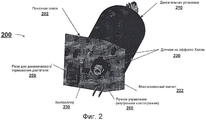
Фиг.2 иллюстрирует примерный аппарат предотвращения перегрузки согласно дополнительному варианту осуществления.2 illustrates an exemplary congestion avoidance apparatus according to a further embodiment.
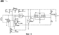
Фиг.3 иллюстрирует принципиальную схему примерной топологии схемы аппарата предотвращения перегрузки фиг.2 согласно варианту осуществления.FIG. 3 illustrates a schematic diagram of an exemplary circuit topology of the apparatus for preventing overload of FIG. 2 according to an embodiment.
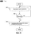
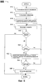
Фиг.4 иллюстрирует блок-схему последовательности операций примерного процесса, которым предотвращается перегрузка двигателя, согласно варианту осуществления.4 illustrates a flowchart of an exemplary process that prevents engine overload according to an embodiment.
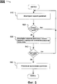
Фиг.5 иллюстрирует блок-схему последовательности операций примерного процесса, которым предотвращается перегрузка двигателя, согласно варианту осуществления.5 illustrates a flowchart of an exemplary process that prevents engine overload according to an embodiment.
Фиг.6 иллюстрирует блок-схему последовательности операций примерного процесса, которым предотвращается перегрузка двигателя, согласно варианту осуществления, и6 illustrates a flowchart of an exemplary process that prevents engine overload according to an embodiment, and
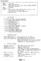
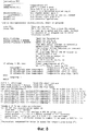
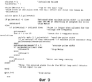
Фиг.7-9 иллюстрирует исходную программу для примерного способа и процесса для предотвращения состояния перегрузки в работе двигателя.7-9 illustrate an initial program for an exemplary method and process for preventing an overload condition in engine operation.
ПОДРОБНОЕ ОПИСАНИЕ РАЗЛИЧНЫХ ВАРИАНТОВ ОСУЩЕСТВЛЕНИЯDETAILED DESCRIPTION OF DIFFERENT EMBODIMENTS
Согласно различным аспектам, созданы устройство, система, способ, компьютерный продукт, компьютерная программа или нечто подобное для предотвращения состояния перегрузки двигателя, например, двигателя постоянного тока с возбуждением от постоянных магнитов, например, как используемый в возвратно-поступательных или поворотных приводах. Основные параметры двигателей постоянного тока с возбуждением от постоянных магнитов линейно зависимы, т.е. повышение нагружающего момента приводит к пропорциональному снижению скорости двигателя и пропорциональному повышению входного тока двигателя. Любая из трех характеристик может быть измерена для прогнозирования состояния двух других. Поскольку скорость двигателя в двигателе постоянного тока с возбуждением от постоянных магнитов обратно пропорциональна току двигателя, скорость является точным прогнозирующим параметром тока. Скорость двигателя (например, RPM двигателя или подобное), следовательно, может использоваться в качестве индикатора нагрузки вместо тока. Соответственно, состояние перегрузки двигателя может быть обнаружено, и могут быть приняты меры по его предотвращению на основе скорости двигателя и ее мониторинга.According to various aspects, an apparatus, system, method, computer product, computer program or the like is provided for preventing an overload condition of an engine, for example, a DC motor driven by permanent magnets, for example, as used in reciprocating or rotary drives. The main parameters of DC motors with excitation from permanent magnets are linearly dependent, i.e. an increase in the load moment leads to a proportional decrease in the motor speed and a proportional increase in the input current of the motor. Any of the three characteristics can be measured to predict the state of the other two. Since the speed of a motor in a DC motor driven by permanent magnets is inversely proportional to the motor current, speed is an accurate predictor of the current. Motor speed (e.g., engine RPM or the like), therefore, can be used as an indicator of load instead of current. Accordingly, an engine overload condition can be detected, and measures can be taken to prevent it based on engine speed and its monitoring.
Согласно примерному осуществлению, подход предотвращения перегрузки может предполагать мониторинг скорости двигателя, обнаружение состояния перегрузки двигателя на основе мониторинга скорости и управление работой двигателя согласно обнаруженному состоянию перегрузки. Например, при пороге скорости или ниже (например, заданная скорость или нечто подобное) подача питания на двигатель прекращается. Порог(и) может быть заранее задан (или заранее установлен) или настроен, изменен или определен динамически на основе текущих условий работы (или окружающей среды) двигателя, например, окружающей температуры, входного напряжения, тока и т.д. Таким образом, порог может быть, например, функцией эксплуатационных характеристик или окружающей среды (например, пороговая величина = минимальная скорость (входное напряжение, температура)). Порог(и) может уточняться во время или перед включением двигателя или во время работы двигателя, по желанию, и может вычисляться или выбираться из таблицы или определяться комбинацией этих способов. Ниже подробно описаны различные примеры осуществления предотвращения перегрузки.According to an exemplary embodiment, an overload prevention approach may involve monitoring engine speed, detecting an engine overload condition based on speed monitoring, and controlling engine operation according to the detected overload condition. For example, at a speed threshold or lower (for example, a predetermined speed or something similar), power to the engine is cut off. The threshold (s) can be predefined (or pre-set) or adjusted, changed or determined dynamically based on the current operating conditions (or the environment) of the motor, for example, ambient temperature, input voltage, current, etc. Thus, the threshold can be, for example, a function of performance or the environment (for example, threshold = minimum speed (input voltage, temperature)). The threshold (s) can be specified during or before the engine is turned on or during engine operation, as desired, and can be calculated or selected from a table or determined by a combination of these methods. Various examples of implementing overload prevention are described in detail below.
Использование скорости в предотвращении перегрузки может обеспечивать, среди прочего, различные примеры эффектов и/или преимуществ. Например, скорость двигателя может отслеживаться с помощью средства, которое не вызывает снижения эффективности по сравнению с традиционными способами. Примеры бесконтактных конфигураций могут включать в себя использование электромагнитного датчика(ов), например, устройства на эффекте Холла, в комбинации с многополюсным магнитом на валу двигателя, использование оптического датчика(ов) и световых технологий и т.д. Это, например, может устранить снижение эффективности, как упоминалось выше. Работа двигателя и его скорость могут вернуться к нормальным, как только неисправность или состояние будет устранена или исправлено, так что задержка сброса, например, связанная с устройством тепловой защиты, не возникает или сокращается. Скорость двигателя также может постоянно отслеживаться, так что время на отклик на состояние неисправности может быть сильно сокращено.Using speed to prevent congestion can provide, among other things, various examples of effects and / or advantages. For example, engine speed can be monitored using a tool that does not cause a decrease in efficiency compared to traditional methods. Examples of non-contact configurations may include the use of an electromagnetic sensor (s), for example, a Hall effect device, in combination with a multi-pole magnet on the motor shaft, the use of optical sensor (s) and lighting technology, etc. This, for example, can eliminate the decrease in efficiency, as mentioned above. The operation of the engine and its speed can return to normal as soon as the malfunction or condition is eliminated or corrected, so that a reset delay, for example, associated with a thermal protector, does not occur or is reduced. Engine speed can also be continuously monitored so that the response time to a fault condition can be greatly reduced.
Более того, путем примера, конфигурации или вариантов осуществления предотвращения перегрузки, описанных здесь, могут быть использованы для предотвращения, среди прочего, следующих состояний: (1) механической перегрузки (например, заклинивание или перегрузки в середине хода), (2) электрической перегрузки (например, превышения номинальной продолжительности включения), (3) остановки в конце хода (например, внутренней в приводе или наружной в приводимом в действие аппарате) и т.д.Moreover, by way of example, configuration, or embodiment, the prevention of overload described herein can be used to prevent, among other things, the following conditions: (1) mechanical overload (e.g., jamming or overload in the middle of the stroke), (2) electrical overload ( for example, exceeding the nominal duration of switching on), (3) stopping at the end of the stroke (for example, internal in the drive or external in the driven device), etc.
Фиг.1 показывает обзор блок-схемы последовательности операций примерного аппарата или системы 100 предотвращения перегрузки (здесь и далее “аппарат”) для двигателя 110 согласно варианту осуществления. Как показано, аппарат 100 предотвращения перегрузки включает в себя датчик 120 для мониторинга скорости двигателя 110; детектор 130 для обнаружения состояния перегрузки двигателя 110 на основе отслеживаемой скорости; контроллер 140 для управления работой двигателя 110 и реле 150 (например, переключатель(и), управляющие схемы и др.), через которое могут управляться операции двигателя (например, приостанавливаться, возобновляться, включаться или выключаться, тормозиться и др.).FIG. 1 shows an overview of a flowchart of an exemplary apparatus or overload prevention system 100 (hereinafter, “apparatus”) for an engine 110 according to an embodiment. As shown, the overload prevention apparatus 100 includes a sensor 120 for monitoring the speed of the engine 110; a detector 130 for detecting an overload condition of the engine 110 based on the monitored speed; a controller 140 for controlling the operation of the engine 110 and a relay 150 (e.g., switch (s), control circuits, etc.) through which engine operations can be controlled (e.g., pause, resume, turn on or off, slow down, etc.).
Датчик 120 скорости может относиться к типу, который не требует физического контакта или не использует его в качестве части операций распознавания или мониторинга скорости двигателя. Например, датчик 120 скорости может быть тахометром или в нем может использоваться электромагнитная конфигурация распознавания, оптическая конфигурация распознавания и т.д. для мониторинга скорости двигателя 110. Одним примером электромагнитной конфигурации распознавания может служить аппарат на эффекте Холла, размещенный или расположенный для распознавания многополюсного магнита, расположенного, например, на валу двигателя 110. В этом примере, подробно описываемом ниже, когда двигатель работает и вал двигателя и магнит на нем вращаются, аппарат на эффекте Холла (или его переключатель(и)) выдает импульсы, в которых ширина импульсов отражает скорость двигателя. Вместо ширины импульсов могут быть использованы другие формы измерения скорости, например, частота. Частота может определяться по ширине импульса за период времени для отражения скорости двигателя. Это только один пример конфигурации распознавания скорости или датчика, и для реализации свойства предотвращения перегрузки могут быть использованы другие конфигурации или датчики, как описано здесь.The speed sensor 120 may be of a type that does not require physical contact or does not use it as part of recognition or monitoring of engine speed. For example, the speed sensor 120 may be a tachometer, or it may use an electromagnetic recognition configuration, an optical recognition configuration, etc. for monitoring the speed of the motor 110. One example of an electromagnetic recognition configuration may be a Hall effect apparatus located or located to recognize a multi-pole magnet located, for example, on the shaft of the motor 110. In this example, described in detail below, when the engine is running and the motor shaft and the magnet rotates on it, the Hall effect apparatus (or its switch (s)) gives out pulses in which the pulse width reflects the speed of the engine. Instead of pulse widths, other forms of velocity measurement, such as frequency, can be used. The frequency can be determined by the pulse width over a period of time to reflect the speed of the engine. This is just one example of a speed recognition or sensor recognition configuration, and other configurations or sensors can be used to implement the overload prevention property, as described here.
Другой тип конфигурации распознавания скорости может предполагать использование оптических датчиков и света. Например, датчик 120 скорости может включать в себя фотоприемник или оптический кодер или нечто подобное для распознавания света, соответствующего скорости двигателя, и выдавать сигнал или информацию, отражающую скорость. Фотоприемник может распознавать (1) свет, отражаемый от компонента на двигателе во время работы, или (2) свет, проецируемый через пазы или отверстия, расположенные относительно двигателя во время работы. В первом примере может быть использован отражательный кодер или нечто подобное, в котором светодиод или другой источник света направляется на двигатель или компонент на нем (например, аналогичным образом на вал) и отражается обратно на фотоприемник, например фотодиод(ы) или фототранзистор(ы) для получения скоростной характеристики двигателя. В другом примере светодиод или другой источник света направляется на пазы или отверстия (расположенные, например, на двигателе или компоненте на нем или относительно них) и обнаруживается фотодетектором, например фотодиодом(ами) или фототранзистором(ами) для получения скоростной характеристики двигателя.Another type of speed recognition configuration may involve the use of optical sensors and light. For example, the speed sensor 120 may include a photodetector or an optical encoder or the like for sensing light corresponding to the speed of the engine, and outputting a signal or information reflecting the speed. The photodetector can recognize (1) the light reflected from the component on the engine during operation, or (2) the light projected through slots or openings located relative to the engine during operation. In the first example, a reflective encoder or something similar can be used in which an LED or other light source is directed to a motor or component on it (for example, in a similar way to a shaft) and reflected back to a photodetector, for example photodiode (s) or phototransistor (s) to obtain the speed characteristics of the engine. In another example, an LED or other light source is directed to grooves or openings (located, for example, on the motor or component on it or relative to them) and detected by a photodetector, such as a photodiode (s) or a phototransistor (s) to obtain a high-speed characteristic of the engine.
В качестве дополнительного примера, датчик 120 скорости может предполагать использование магнитоуправляемого контакта(ов) в комбинации с магнитом(ами) для распознавания скорости двигателя во время его работы. Пример магнитоуправляемого контакта может использоваться в конфигурациях двигателя с более низкой скоростью. Нижеследующие конфигурации являются просто примерами различных конфигураций распознавания скорости и других конфигураций распознавания скорости, которые могут быть использованы для предотвращения перегрузки, описанной выше.As an additional example, the speed sensor 120 may involve the use of magnetically controlled contact (s) in combination with magnet (s) to detect the speed of the engine during its operation. An example of a magnetically controlled contact can be used in lower speed motor configurations. The following configurations are merely examples of various speed recognition configurations and other speed recognition configurations that can be used to prevent the overload described above.
Различные компоненты и процессы аппарата 100 предотвращения перегрузки, как описано выше, могут дополнительно реализовываться через один или более процессоров, выполняющих машиночитаемый код (например, программу, программное обеспечение или микропрограммное обеспечение и др.), проводную систему или интегральные или логические схемы или их комбинацию. Машиночитаемый код может храниться в материальной среде памяти и считываться и выполняться для реализации свойства предотвращения перегрузки, описываемого здесь.The various components and processes of the overload prevention apparatus 100, as described above, may be further implemented through one or more processors executing computer readable code (eg, program, software or firmware, etc.), a wired system, or integrated or logic circuits or a combination thereof . Machine-readable code may be stored in a material memory medium and read and executed to implement the overload prevention property described herein.
Фиг.2 показывает обзор блок-схемы последовательности операций примерного аппарата 200 предотвращения перегрузки для двигателя (или двигательной установки) 210 согласно дополнительному варианту осуществления. Как показано, аппарат 110 предотвращения перегрузки может включать в себя датчики 220 Холла (например, переключатели на эффекте Холла), контроллер 230 для реализации различных функций и свойств предотвращения перегрузки, например, как описываемые здесь, и реле 250 для динамического торможения двигателя 210. В этом примере эти компоненты аппарата 200 расположены на печатной плате 202.FIG. 2 shows an overview of a flowchart of an exemplary
Датчики 220 Холла расположены для считывания магнитного поля с многополюсного магнита 222, расположенного или подсоединенного на валу двигателя 210 для вращения со скоростью двигателя. Магнит 222 может быть 12-полюсным или 6-полюсным парным магнитным устройством, которое прикреплено к валу двигателя 210. Во время работы магнит 222 возбуждает переключатель(и) на эффекте Холла каждый раз, когда южный полюс проходит поверхность переключателя(ей) на эффекте Холла датчиков 220. Результирующая ширина импульса, выдаваемая датчиками 220, отражает скорость (например, обороты/мин) двигателя 210.Hall sensors 220 are arranged to read a magnetic field from a
Контроллер 230 может включать в себя микропроцессор(ы) или микроконтроллер(ы), который получает отслеживаемую скорость, обнаруживает состояние перегрузки двигателя на основе отслеживаемой скорости и управляет работой двигателя согласно обнаруженному состоянию перегрузки. Например, при пороге скорости или перед ним (например, заданная величина скорости или нечто подобное) подача питания на двигатель прекращается, например, через реле 250 или другие реле или управляющие схемы или компоненты двигателя.The controller 230 may include microprocessor (s) or microcontroller (s) that obtains a monitored speed, detects an engine overload condition based on the monitored speed, and controls the operation of the engine according to the detected overload condition. For example, at or in front of the speed threshold (for example, a predetermined speed value or something similar), the power supply to the engine is interrupted, for example, through
Также на фиг.2 показана функция или конфигурация 260 ручного управления, которая может использоваться для вращения, эксплуатации или перемещения вручную вала или соединенных с ним компонентов, например, в случае перегрузки или неисправности или выхода из строя или отказа питания и т.д.2 also shows a manual control function or
Хотя фиг.2 описывает один пример, в котором используются конкретные компоненты и конфигурация этих компонентов, для мониторинга состояния перегрузки согласно скорости двигателя могут использоваться эти и/или другие компоненты и устройства. Например, как отмечалось выше, может быть использован датчик, отличный от переключателей на эффекте Холла, например, оптические датчики и т.д. Тип датчика может быть выбран, например, на основе применения двигателя и условий эксплуатации двигателя.Although FIG. 2 describes one example in which specific components and the configuration of these components are used, these and / or other components and devices may be used to monitor overload conditions according to engine speed. For example, as noted above, a sensor other than Hall effect switches, such as optical sensors, etc., may be used. The type of sensor can be selected, for example, based on the application of the engine and the operating conditions of the engine.
Фиг.3 показывает принципиальную схему примера топологии схемы аппарата 200 предотвращения перегрузки фиг.2 согласно варианту осуществления. Как показано, аппарат 200 предотвращения перегрузки включает в себя выводы W1-W4, конденсаторы С1-С4 и С5, резисторы R1-R5, диоды D1, D2, D4, двухполупериодный выпрямительный мост (или выпрямитель) D3, реле RLY1, регулятор напряжения U1, микропроцессор U2, датчик температуры U3, транзистор Q1 и аппарат или переключатель на эффекте Холла НЕ1.FIG. 3 shows a schematic diagram of an example topology of a circuit of the apparatus for preventing overload of FIG. 2 according to an embodiment. As shown, the
Выводы W1 и W2 обеспечивают подвод питания. Вывод W1- положительный для одного направления вращения двигателя и отрицательный для обратного направления. Это напряжение прикладывается ко входу двухполупериодного выпрямительного моста D3, а также к контактам однополюсного двухпозиционного реле RLY1. Двухполупериодный выпрямительный мост D3 подает напряжение соответствующей полярности на схему управления аппарата 200 вне зависимости от входной полярности.Pins W1 and W2 provide power supply. Terminal W1 is positive for one direction of rotation of the engine and negative for the opposite direction. This voltage is applied to the input of the half-wave rectifier bridge D3, as well as to the contacts of the single-pole two-position relay RLY1. The half-wave rectifier bridge D3 supplies voltage of the corresponding polarity to the control circuit of
Резисторы R2 и R3 образуют делитель напряжения. Величины резисторов могут выбираться для обеспечения желаемого напряжения, например, напряжения 5 В или ниже, на резисторе R3. Стабилитрон D2 используется для обеспечения того, чтобы напряжение не превышало входное напряжение на микропроцессор U2. Напряжение на резисторе R3 пропорционально входному напряжению, прикладываемому к приводу, и используется для отслеживания входного напряжения. Как более подробно описано ниже, входное напряжение может получаться или считываться для изменения или настройки или определения величины порога скорости (или предела), используемой для обнаружения состояния перегрузки.Resistors R2 and R3 form a voltage divider. The values of the resistors can be selected to provide the desired voltage, for example, a voltage of 5 V or lower, on the resistor R3. The Zener diode D2 is used to ensure that the voltage does not exceed the input voltage to the microprocessor U2. The voltage across resistor R3 is proportional to the input voltage applied to the drive and is used to track the input voltage. As described in more detail below, the input voltage can be obtained or read to change or adjust or determine the magnitude of the speed threshold (or limit) used to detect an overload condition.
Конденсаторы С1 и С2 используются для стабилизации подачи напряжения на вход регулятора напряжения U1.Capacitors C1 and C2 are used to stabilize the voltage supply to the input of the voltage regulator U1.
Диод D1 предотвращает превышение напряжения, вызываемое индуктивностью катушки реле RLY1, когда она выключается. Транзистор Q1 используется для включения и выключения катушки реле RLY1 согласно сигналам, применяемым к базе транзистора через резистор R4.Diode D1 prevents overvoltage caused by the inductance of the relay coil RLY1 when it is turned off. Transistor Q1 is used to turn on and off the relay coil RLY1 according to the signals applied to the base of the transistor through resistor R4.
Выход регулятора напряжения U1 фильтруется конденсаторами С3 и С4. Это обеспечивает стабильную подачу напряжения на микропроцессор U2 и переключатель на эффекте Холла НЕ1. Переключатель на эффекте Холла НЕ1 обеспечивает выходной импульс каждый раз, когда его проходит полюс магнита. Ширина импульса пропорциональна скорости вращения двигателя.The output of the voltage regulator U1 is filtered by capacitors C3 and C4. This provides a stable voltage supply to the microprocessor U2 and the Hall effect switch HE1. The Hall effect switch HE1 provides an output pulse every time a magnet pole passes through it. The pulse width is proportional to the engine speed.
Резистор R5 ограничивает протекание тока на светодиод (LED) D4. Диод D4 загорается, когда схема управления микропроцессора выключает двигатель, например, в случае состояния перегрузки.Resistor R5 limits the flow of current to the LED (LED) D4. Diode D4 lights up when the microprocessor control circuit turns off the engine, for example, in the event of an overload condition.
Датчик температуры U3 используется для мониторинга окружающей температуры (например, величины окружающей температуры). Поскольку привод может работать при широко изменяющихся температурных условиях, реализация предотвращения перегрузки может учитывать окружающую температуру. Как более подробно описано ниже, окружающая температура может получаться или считываться для изменения или настройки величины порога скорости (или предела), используемой для обнаружения состояния перегрузки.The temperature sensor U3 is used to monitor the ambient temperature (for example, the value of the ambient temperature). Since the drive can operate under widely varying temperature conditions, the implementation of overload prevention can take into account the ambient temperature. As described in more detail below, the ambient temperature can be obtained or read to change or adjust the value of the speed threshold (or limit) used to detect an overload condition.
Ниже описаны примеры функций и свойств, управляемых микропроцессором U2, со ссылкой на листинг исходного текста программы фиг.7-9, который описывает пример процесса(ов) или программы, реализуемой через один или более процессоров для обеспечения предотвращения перегрузки.The following describes examples of functions and properties controlled by the microprocessor U2, with reference to the listing of the source code of the program of Figures 7-9, which describes an example of the process (s) or program implemented through one or more processors to prevent overloading.
Например, когда питание в первый раз подается на микропроцессор U2, выход GP5 становится HIGH (высокий). Это включает транзистор Q1, который возбуждает катушку реле RLY1. Контакты реле RLY1 замыкаются, тем самым подавая питание на двигатель привода, например, на выводах W3 и W4 (соединяемых с двигателем), к которым подсоединен конденсатор С6 для подавления помех. Это поддерживается в течение заданного времени, например, 0,5 секунд. Это заданное время может быть выбрано так, что, например, двигатель может достичь скорости, и входное напряжение может подскочить, если оно упало из-за стартового тока двигателя.For example, when power is first supplied to the microprocessor U2, the output of GP5 becomes HIGH. This turns on transistor Q1, which energizes the relay coil RLY1. The relay contacts RLY1 are closed, thereby supplying power to the drive motor, for example, at terminals W3 and W4 (connected to the motor), to which capacitor C6 is connected to suppress interference. This is maintained for a predetermined time, for example, 0.5 seconds. This predetermined time can be selected so that, for example, the motor can reach speed and the input voltage can jump if it drops due to the starting current of the motor.
В этот момент входное напряжение считывается аналого-цифровым (A/D) преобразователем в микропроцессоре U2. Величина выхода аналого-цифрового (A/D) преобразователя преобразуется математически в минимальную допустимую ширину импульса.At this point, the input voltage is read by an analog-to-digital (A / D) converter in microprocessor U2. The output of the analog-to-digital (A / D) converter is mathematically converted to the minimum allowable pulse width.
Измеряется ширина каждого выходного импульса аппарата на эффекте Холла. Если изменение в импульсе отсутствует, может быть принято, что двигатель не вращается и питание двигателя выключено. Ширина импульса сравнивается с порогом скорости, который может быть установлен базовой величиной RPM (об/мин), и, если желательно, также корректируется или вводится поправка на входное напряжение и окружающую температуру. Если ширина импульса меньше пороговой величины (например, скорость двигателя больше или равна пороговой скорости), тогда работа двигателя продолжается. Если ширина импульса больше пороговой величины (например, скорость двигателя меньше пороговой скорости), микропроцессор U2 усредняет ширину следующих двенадцати импульсов. Если средняя ширина импульса больше пороговой величины (например, средняя скорость двигателя меньше пороговой скорости), двигатель выключается. Работа двигателя продолжается, пока подача питания не будет прекращена или скорость двигателя не упадет ниже минимальной величины. Двигатель может быть выключен выключением транзистора Q1 для подачи команды реле RLY1 разомкнуть контакты, тем самым прекращая подачу питания на двигатель.The width of each output pulse of the apparatus on the Hall effect is measured. If there is no change in the pulse, it can be assumed that the motor does not rotate and the motor power is turned off. The pulse width is compared with a speed threshold that can be set by the base RPM (rpm), and, if desired, an input voltage and ambient temperature are also adjusted or corrected. If the pulse width is less than the threshold value (for example, the engine speed is greater than or equal to the threshold speed), then the engine continues. If the pulse width is greater than the threshold value (for example, the motor speed is less than the threshold speed), the microprocessor U2 averages the width of the next twelve pulses. If the average pulse width is greater than the threshold value (for example, the average engine speed is less than the threshold speed), the engine turns off. Engine operation continues until power is shut off or engine speed drops below the minimum value. The motor can be turned off by turning off the transistor Q1 to instruct the relay RLY1 to open the contacts, thereby cutting off the power supply to the motor.
Фиг.4 показывает блок-схему операций примерного процесса 400, которым предотвращается перегрузка двигателя согласно варианту осуществления. Этот процесс может быть реализован аппаратом предотвращения перегрузки, например, аппаратом 100 или 200 или его компонентами.FIG. 4 shows a flowchart of an
Процесс 400 отслеживает скорость двигателя на этапе 410. На этапе 420 устройство предотвращения перегрузки обнаруживает, присутствует ли состояние перегрузки (или не присутствует) на основе отслеживаемой скорости. Это может предполагать, например, сравнение отслеживаемой скорости или среднего значения отслеживаемой скорости (за период времени или несколько измерений) с порогом (или пределом). Например, если отслеживаемая скорость меньше, чем порог скорости, тогда присутствует состояние перегрузки. Величина порога и способ сравнения (например, меньше, равно и/или больше) могут также зависеть от того, используется ли ширина импульса, частота или другая характеристика для мониторинга и сравнения скорости. Дополнительно к этому, порог может быть изменен, настроен или определен на основе эксплуатационной среды двигателя, например, окружающей температуры, входного напряжения, тока или других характеристик двигателя или факторов окружающей среды, которые могут влиять на работу двигателя, или их комбинации.
Если состояние перегрузки обнаружено, аппарат предотвращения перегрузки соответственно управляет работой двигателя, например, выключает, выключает подачу питания, приостанавливает и т.д. двигатель. Как только состояние перегрузки исправляется или устраняется, двигатель может быть включен или подано питание на двигатель, или работа двигателя может быть возобновлена вместе со свойством предотвращения перегрузки. В противном случае, процесс 400 переходит к этапу 410 для продолжения мониторинга скорости.If an overload condition is detected, the overload prevention apparatus accordingly controls the operation of the engine, for example, turns off, turns off the power supply, suspends, etc. engine. As soon as the overload condition is corrected or eliminated, the engine can be turned on or energized to the engine, or the engine operation can be resumed along with the overload prevention property. Otherwise, the
Фиг.5 показывает блок-схему последовательности операций примера процесса 500, которым предотвращается перегрузка двигателя согласно варианту осуществления. Этот процесс может быть реализован аппаратом предотвращения перегрузки, например, аппаратом 100 или 200 или его компонентами.5 shows a flowchart of an
Процесс 500 отслеживает скорость двигателя на этапе 510. После этого аппарат предотвращения перегрузки обнаруживает, присутствует ли состояние перегрузки (или не присутствует) на основе отслеживаемой скорости. Например, на этапе 520 аппарат предотвращения перегрузки сравнивает отслеживаемую скорость с первым порогом скорости. Если отслеживаемая скорость не меньше или равна первому порогу скорости, тогда процесс 500 переходит обратно к этапу 510. В противном случае, если отслеживаемая скорость меньше или равна первому порогу скорости, тогда аппарат предотвращения перегрузки отслеживает скорость двигателя в течение заданного периода или заданного количества измерений наэтапе 530. Аппарат предотвращения перегрузки сохраняет отслеживаемую скорость (включая или не включая начальное измерение скорости на этапе 510) и вычисляет среднюю скорость за период времени или количество измерений. На этапе 540 аппарат предотвращения перегрузки определяет, меньше ли средняя скорость или равна второму порогу скорости. Первый и второй пороги скорости могут быть одинаковыми или различными. Если средняя скорость не меньше или равна второму порогу скорости, тогда процесс 500 переходит к этапу 510.
В противном случае, если средняя скорость меньше или равна второму порогу скорости, тогда аппарат предотвращения перегрузки обнаруживает состояние перегрузки и управляет выключением двигателя соответственно на этапе 550. Как только состояние перегрузки исправляется или устраняется, двигатель может быть включен или подано питание на двигатель, или работа двигателя может быть возобновлена вместе со свойством предотвращения перегрузки.Otherwise, if the average speed is less than or equal to the second speed threshold, then the overload prevention apparatus detects the overload condition and controls the engine shutdown, respectively, at
Величина первого и второго порогов и способ сравнения (например, меньше, равно и/или больше) могут зависеть от того, используется ли ширина импульса, частота или другая характеристика для мониторинга и сравнения скорости. Дополнительно к этому, пороги могут быть изменены, настроены или определены на основе эксплуатационной среды двигателя, например окружающей температуры, входного напряжения, тока или других характеристик двигателя или факторов окружающей среды, которые могут влиять на работу двигателя, или их комбинации.The magnitude of the first and second thresholds and the comparison method (for example, less, equal, and / or more) may depend on whether the pulse width, frequency, or other characteristic is used to monitor and compare the speed. Additionally, thresholds can be changed, adjusted, or determined based on the operating environment of the engine, for example, ambient temperature, input voltage, current, or other characteristics of the engine or environmental factors that may affect the operation of the engine, or combinations thereof.
Фиг.6 показывает блок-схему последовательности операций примера процесса 600, которым предотвращается перегрузка двигателя согласно варианту осуществления. Этот процесс может быть реализован аппаратом предотвращения перегрузки, например, аппаратом 100 или 200 или его компонентами.6 shows a flowchart of an
Процесс 600 считывает входное напряжение на этапе 610 и считывает температуру на этапе 612. На этапе 614 порог(и) скорости определяется или настраивается согласно условиям эксплуатации, например, входному напряжению и/или температуре. Порог(и) скорости может быть вычислен или получен из справочной таблицы или чего-либо подобного или определен комбинацией этих способов.
На этапе 616 отслеживается скорость двигателя. На этапе 618 аппарат предотвращения перегрузки определяет, включен ли двигатель или работает на основе скорости. Например, когда для измерения скорости двигателя используется выход ширины импульса датчика на эффекте Холла, аппарат предотвращения перегрузки может определить, что двигатель выключен или не работает, если нет изменения (например, нет импульса). Если двигатель выключен, тогда процесс 600 прекращается. В противном случае, если двигатель включен, аппарат предотвращения перегрузки сравнивает отслеживаемую скорость с порогом скорости на этапе 620. Если отслеживаемая скорость не меньше или равна порогу скорости, тогда процесс 600 переходит обратно к этапу 616. В противном случае, если отслеживаемая скорость меньше или равна порогу скорости, тогда аппарат предотвращения перегрузки отслеживает скорость двигателя в течение заданного периода или заданного количества измерений на этапе 622. Устройство предотвращения перегрузки сохраняет отслеживаемую скорость (включая или не включая начальное измерение скорости на этапе 616) и вычисляет среднюю скорость за период времени или количество измерений. На этапе 624 аппарат предотвращения перегрузки определяет, меньше ли средняя скорость или равна порогу скорости. В этом примере на этапах 620 и 624 используются одинаковые пороговые скорости, но они могут быть различными, если желательно. Если средняя скорость не меньше или равна второму порогу скорости, тогда процесс 600 переходит к этапу 616.At 616, the engine speed is monitored. At
В противном случае, если средняя скорость меньше или равна второй порогу скорости, тогда аппарат предотвращения перегрузки обнаруживает состояние перегрузки и управляет выключением двигателя соответственно на этапе 626. Как только перегрузка или состояние неисправности исправляется или устраняется, двигатель может быть включен или подано питание на двигатель, или работа двигателя может быть возобновлена вместе со свойством предотвращения перегрузки.Otherwise, if the average speed is less than or equal to the second speed threshold, then the overload prevention apparatus detects the overload condition and controls the engine shutdown, respectively, at
Величина порога и способ сравнения (например, меньше, равно и/или больше) могут зависеть от того, используется ли ширина импульса, частота или другая характеристика для мониторинга и сравнения скорости. Дополнительно к этому, пороги могут быть изменены, настроены или определены на основе эксплуатационной среды двигателя, например, окружающей температуры, входного напряжения, тока или других характеристик двигателя или факторов окружающей среды, которые могут влиять на работу двигателя, или их комбинации.The threshold value and the comparison method (for example, less, equal and / or more) may depend on whether the pulse width, frequency, or other characteristic is used to monitor and compare the speed. In addition, thresholds can be changed, adjusted, or determined based on the operating environment of the engine, for example, ambient temperature, input voltage, current, or other characteristics of the engine or environmental factors that may affect engine operation, or combinations thereof.
Хотя фиг.4-6 выше описывают примерные процессы для предотвращения перегрузки двигателя, свойство предотвращения перегрузки не ограничивается конкретными этапами, порядком этапов или реализацией, описанными в этих примерах. Различные варианты, например, как описанные на этих фиг.4-6 и повсеместно здесь, включающие, среди прочего, конкретный тип измерения скорости, порог, количество сравнений с порогом и т.д., могут быть выбраны по желанию. Различные процессы могут быть реализованы через один или более процессоров, выполняющих машино-читаемый код (например, программу, программное или микропрограммное обеспечение и др.), проводную систему или интегральные или логические схемы или их комбинацию.Although FIGS. 4-6 above describe exemplary processes for preventing engine overload, the overload prevention property is not limited to the specific steps, order of steps, or implementation described in these examples. Various options, for example, as described in these FIGS. 4-6 and throughout, including, but not limited to, a specific type of speed measurement, threshold, number of comparisons with a threshold, etc., can be selected as desired. Various processes can be implemented through one or more processors that execute machine-readable code (for example, a program, software or firmware, etc.), a wired system, or integrated or logic circuits or a combination thereof.
Хотя выше описаны различные варианты осуществления настоящего изобретения, следует понимать, что они представлены только в качестве примера и не являются ограничением. Соответственно, для специалистов в данной области техники очевидно, что в них могут быть внесены различные изменения в форме и деталях без отклонения от сущности и объема изобретения. Таким образом, широта и объем настоящего изобретения не должны ограничиваться каким-либо из описанных выше примеров осуществления, но должны определяться только согласно нижеследующей формуле изобретения и ее эквивалентам. Таким образом, в объем настоящего изобретения входят и другие типы двигателей.Although various embodiments of the present invention have been described above, it should be understood that they are presented by way of example only and are not limiting. Accordingly, it will be apparent to those skilled in the art that various changes can be made to them in form and detail without departing from the spirit and scope of the invention. Thus, the breadth and scope of the present invention should not be limited to any of the above embodiments, but should be determined only in accordance with the following claims and their equivalents. Thus, other types of engines are also within the scope of the present invention.
Claims (23)
обнаружение состояния нагрузки двигателя на основе отслеживаемой скорости для определения состояния хода двигателя, причем обнаружение содержит сравнение отслеживаемой скорости с первым порогом скорости и в зависимости от этого сравнения вычисление средней скорости за период времени или за количество измерений скорости и определение, существует состояние нагрузки или нет, на основе сравнения вычисленной средней скорости с порогом средней скорости; и управление работой двигателя согласно обнаруженному состоянию перегрузки.1. A method of controlling engine operation according to a load condition, comprising: monitoring engine speed;
detecting the engine load state based on the monitored speed to determine the engine stroke state, the detection comprising comparing the monitored speed with the first speed threshold and, depending on this comparison, calculating the average speed over a period of time or over the number of speed measurements and determining whether the load condition exists or not, based on comparing the calculated average speed with the average speed threshold; and controlling engine operation according to the detected overload condition.
Applications Claiming Priority (2)
| Application Number | Priority Date | Filing Date | Title |
|---|---|---|---|
| US11/461,170 US7622876B2 (en) | 2006-07-31 | 2006-07-31 | Overload prevention device for permanent magnet DC motors |
| US11/461,170 | 2006-07-31 |
Publications (2)
| Publication Number | Publication Date |
|---|---|
| RU2009107021A RU2009107021A (en) | 2010-09-10 |
| RU2442257C2 true RU2442257C2 (en) | 2012-02-10 |
Family
ID=38985993
Family Applications (1)
| Application Number | Title | Priority Date | Filing Date |
|---|---|---|---|
| RU2009107021/07A RU2442257C2 (en) | 2006-07-31 | 2007-05-31 | Device for prevention of permanent magnet direct current motor overload |
Country Status (10)
| Country | Link |
|---|---|
| US (1) | US7622876B2 (en) |
| EP (1) | EP2050174A4 (en) |
| JP (1) | JP2009545946A (en) |
| CN (1) | CN101501952A (en) |
| BR (1) | BRPI0714699A2 (en) |
| CA (1) | CA2657624A1 (en) |
| MX (1) | MX2009000794A (en) |
| RU (1) | RU2442257C2 (en) |
| UA (1) | UA94761C2 (en) |
| WO (1) | WO2008016744A2 (en) |
Families Citing this family (17)
| Publication number | Priority date | Publication date | Assignee | Title |
|---|---|---|---|---|
| US8972032B2 (en) * | 2009-06-25 | 2015-03-03 | GM Global Technology Operations LLC | Method for overload protection of SMA device |
| US8744603B2 (en) * | 2009-06-26 | 2014-06-03 | GM Global Technology Operations LLC | Method for position feedback based control for overload protection |
| GB2473803A (en) | 2009-07-02 | 2011-03-30 | Pg Drives Technology Ltd | Prevention of motor overload by calculation of motor resitance and temperature |
| US9030143B2 (en) | 2011-10-31 | 2015-05-12 | Regal Beloit America, Inc. | Method and system of limiting current to a motor |
| CN102412563B (en) * | 2011-11-21 | 2014-03-12 | 哈尔滨电机厂有限责任公司 | Motor start-up procedure protector |
| JP5664543B2 (en) * | 2011-12-26 | 2015-02-04 | 東京エレクトロン株式会社 | Conveying apparatus and conveying method |
| DE112015003676T5 (en) * | 2014-08-08 | 2017-05-04 | Johnson Electric S.A. | Engine component and integrated circuit for driving the engine |
| WO2017011568A1 (en) * | 2015-07-13 | 2017-01-19 | W.W. Grainger, Inc. | Methods and apparatus for securing a sensor to a monitored device |
| WO2017106303A1 (en) | 2015-12-14 | 2017-06-22 | Milw A Ukee Electric Tool Corporation | Overload detection in a power tool |
| US9862001B2 (en) * | 2015-12-31 | 2018-01-09 | Sulzer Mixpac Ag | Dispensing device |
| EP3299127A1 (en) | 2016-06-24 | 2018-03-28 | Black & Decker Inc. | Control scheme for operating cordless power tool based on battery temperature |
| JP6613215B2 (en) * | 2016-08-03 | 2019-11-27 | ミネベアミツミ株式会社 | Motor control circuit, motor control device, actuator, and stepping motor control method |
| JP6603629B2 (en) * | 2016-08-03 | 2019-11-06 | ミネベアミツミ株式会社 | Motor control circuit, motor control device, actuator, and stepping motor control method |
| CN107508509B (en) * | 2017-08-11 | 2019-12-31 | 常州机电职业技术学院 | Brushless direct current motor control method and device and low-speed heavy-load control method thereof |
| CN108216461A (en) * | 2017-12-22 | 2018-06-29 | 深圳天轮科技有限公司 | Balancing bicycle motor method of controlling security and device |
| CN209236025U (en) * | 2017-12-23 | 2019-08-13 | 天佑电器(苏州)有限公司 | Driving device and burnisher |
| CN112953356B (en) * | 2019-12-11 | 2023-12-15 | 武汉杰开科技有限公司 | Method, system and readable storage medium based on motor locked rotor protection |
Family Cites Families (19)
| Publication number | Priority date | Publication date | Assignee | Title |
|---|---|---|---|---|
| JPS58107022A (en) * | 1981-12-21 | 1983-06-25 | 日本ビクター株式会社 | Circuit for protecting motor |
| USRE33379E (en) * | 1984-03-23 | 1990-10-09 | Black & Decker Inc. | Microprocessor based motor control |
| JPS6368440A (en) * | 1986-09-11 | 1988-03-28 | N S K Warner Kk | Passive seat belt system |
| US4961880A (en) * | 1988-08-31 | 1990-10-09 | Altran Corporation | Electrostatic voltage excitation process and apparatus |
| JPH03164024A (en) * | 1989-11-17 | 1991-07-16 | Tachi S Co Ltd | Method of protective motor from overload |
| US5218282A (en) * | 1990-03-22 | 1993-06-08 | Stanley Home Automation | Automatic door operator including electronic travel detection |
| US5336167A (en) * | 1991-07-22 | 1994-08-09 | Theratek International, Inc. | Controller for intravascular catheter system |
| CA2085202C (en) * | 1992-03-24 | 1996-10-22 | Ricky L. Bunch | Positive temperature coefficient start winding protection |
| US6064165A (en) * | 1992-04-22 | 2000-05-16 | Nartron Corporation | Power window or panel controller |
| DE4315182A1 (en) * | 1993-05-07 | 1994-11-10 | Bosch Gmbh Robert | Electric motor drive |
| DE4432058A1 (en) * | 1994-09-09 | 1996-03-14 | Bosch Gmbh Robert | Circuit for operating an electric motor |
| US6026926A (en) * | 1997-07-25 | 2000-02-22 | Honda Giken Kogyo Kabushiki Kaisha | Electric power steering apparatus |
| US6011376A (en) * | 1998-03-13 | 2000-01-04 | Cincinnati Milacron Inc. | Method and apparatus for injection molding machine control |
| US6201369B1 (en) * | 1998-10-02 | 2001-03-13 | Siemens Energy & Automation, Inc. | SCR protection from stalled motor without current sensing |
| KR100320178B1 (en) * | 1999-02-01 | 2002-01-10 | 구자홍 | Speed control method for switched reluctance motor |
| US6118243A (en) * | 1999-04-07 | 2000-09-12 | Overhead Door Corporation | Door operator system |
| US6806664B2 (en) * | 2001-03-15 | 2004-10-19 | Stoneridge Control Devices, Inc. | Electro-mechanical actuator including brushless DC motor for providing pinch protection |
| US6933694B2 (en) * | 2003-11-24 | 2005-08-23 | Valeo Electrical Systems, Inc. | Control for electric motor in vehicles |
| JP2005253200A (en) * | 2004-03-04 | 2005-09-15 | Honda Motor Co Ltd | Method and device for controlling rotary electric machine |
-
2006
- 2006-07-31 US US11/461,170 patent/US7622876B2/en not_active Expired - Fee Related
-
2007
- 2007-05-31 CA CA002657624A patent/CA2657624A1/en not_active Abandoned
- 2007-05-31 WO PCT/US2007/070097 patent/WO2008016744A2/en active Application Filing
- 2007-05-31 UA UAA200901626A patent/UA94761C2/en unknown
- 2007-05-31 RU RU2009107021/07A patent/RU2442257C2/en not_active IP Right Cessation
- 2007-05-31 CN CNA2007800279319A patent/CN101501952A/en active Pending
- 2007-05-31 JP JP2009522907A patent/JP2009545946A/en active Pending
- 2007-05-31 MX MX2009000794A patent/MX2009000794A/en active IP Right Grant
- 2007-05-31 BR BRPI0714699-0A patent/BRPI0714699A2/en not_active IP Right Cessation
- 2007-05-31 EP EP07784248A patent/EP2050174A4/en not_active Withdrawn
Non-Patent Citations (1)
| Title |
|---|
| US Re 33379, 09.10.1990. * |
Also Published As
| Publication number | Publication date |
|---|---|
| UA94761C2 (en) | 2011-06-10 |
| US20080024940A1 (en) | 2008-01-31 |
| WO2008016744A2 (en) | 2008-02-07 |
| WO2008016744A3 (en) | 2008-08-21 |
| EP2050174A2 (en) | 2009-04-22 |
| BRPI0714699A2 (en) | 2013-02-19 |
| JP2009545946A (en) | 2009-12-24 |
| CA2657624A1 (en) | 2008-02-07 |
| CN101501952A (en) | 2009-08-05 |
| RU2009107021A (en) | 2010-09-10 |
| MX2009000794A (en) | 2009-04-09 |
| EP2050174A4 (en) | 2012-05-09 |
| US7622876B2 (en) | 2009-11-24 |
Similar Documents
| Publication | Publication Date | Title |
|---|---|---|
| RU2442257C2 (en) | Device for prevention of permanent magnet direct current motor overload | |
| US8476853B2 (en) | Redundant overspeed protection for power tools | |
| US9991826B2 (en) | Motor control circuit, motor drive control apparatus and control method of motor drive control apparatus | |
| US9413276B2 (en) | DC motor control over wide dynamic range | |
| CA2513550A1 (en) | Brushless and sensorless dc motor control system with locked and stopped rotor detection | |
| US7208909B2 (en) | Motor protection inhibit circuit | |
| JP4607012B2 (en) | Motor control method and motor control apparatus | |
| JPH09168227A (en) | Overload protector | |
| JP2002531044A (en) | System and method for protecting electric motor and its control circuit, and electric motor | |
| US7068008B2 (en) | Electronic device for controlling a discharge pump driven by a synchronous electric motor with a permanent-magnet rotor | |
| KR100928939B1 (en) | The coil drive circuit of the electromagnetic contactor | |
| US9367376B2 (en) | Drive control device | |
| JP2005295605A (en) | Motor control method and motor controller | |
| US7902777B2 (en) | Method and system for motor oscillatory state detection | |
| JP2009055783A (en) | Air conditioner | |
| JP2004260943A (en) | Method and apparatus for controlling operation of variable speed motor | |
| JP2008052440A (en) | Data holding device | |
| KR20070116766A (en) | Start relay for overload protection of single-phase induction motor | |
| WO2012114071A9 (en) | Protection circuitry for monitoring the power devices controlling the exciter current of an electrical generator | |
| KR100671166B1 (en) | Load and speed sensitive motor starting circuit and nethod | |
| Chavan et al. | PIC based protection of single phase induction motor | |
| KR100749067B1 (en) | Control method of bldc motors | |
| JPH07177649A (en) | Overload stopping circuit for motor | |
| KR19980048108A (en) | Inverter with dynamic braking circuit | |
| KR20060079873A (en) | Driving apparatus of a motor and control method thereof |
Legal Events
| Date | Code | Title | Description |
|---|---|---|---|
| MM4A | The patent is invalid due to non-payment of fees |
Effective date: 20120601 |